1
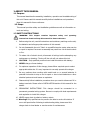
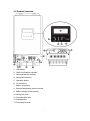
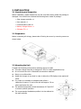
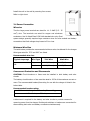
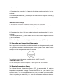
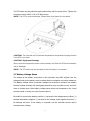
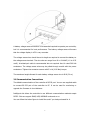
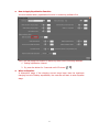
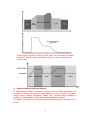
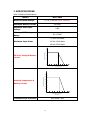
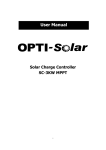
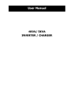
MPPT SOLAR CHARGER 3KW PCM60X User Manual Version 1.2 CONTENTS 1 ABOUT THIS MANUAL ...........................................................................................1 1.1 Purpose ......................................................................................................1 1.2 Scope .........................................................................................................1 1.3 SAFETY INSTRUCTIONS ...............................................................................1 2 INTRODUCTION....................................................................................................2 2.1 Features......................................................................................................2 2.2 Product Overview.........................................................................................3 3. INSTALLATION .....................................................................................................4 3.1 Unpacking and Inspection .............................................................................4 3.2 Preparation .................................................................................................4 3.3 Mounting the Unit ........................................................................................4 3.4 Power Connection ........................................................................................5 3.5 Grounding and Ground Fault Interruption .......................................................7 3.6 Remote Temperature Sensor .........................................................................7 3.7 Battery Voltage Sense ..................................................................................8 3.8 Communication Connections .........................................................................9 4. OPERATION ....................................................................................................... 11 4.1 Power-Up .................................................................................................. 11 4.2 Operation and Display Panel........................................................................ 11 4.2 LCD Display Icons ...................................................................................... 12 4.3 Reference Code ......................................................................................... 17 5. CHARGING LOGIC .............................................................................................. 18 5.1 3-stage Charging ....................................................................................... 18 5.2 Equalize Stage ........................................................................................... 20 5.3 Setting Parameter and Default Value ............................................................ 23 6. TROUBLE SHOOTING ......................................................................................... 24 7. SPECIFICATIONS ................................................................................................ 25 2 1 ABOUT THIS MANUAL 1.1 Purpose This manual describes the assembly, installation, operation and troubleshooting of this unit. Please read this manual carefully before installations and operations. Keep this manual for future reference. 1.2 Scope This manual provides safety and installation guidelines as well as information on tools and wiring. 1.3 SAFETY INSTRUCTIONS WARNING: This chapter contains important safety and operating instructions. Read and keep this manual for future reference. 1. Before using the unit, read all instructions and cautionary markings on the unit, the batteries and all appropriate sections of this manual. 2. Do not disassemble the unit. Take it to a qualified service center when service or repair is required. Incorrect re-assembly may result in a risk of electric shock or fire. 3. To reduce risk of electric shock, disconnect all wirings before attempting any maintenance or cleaning. Turning off the unit will not reduce this risk. 4. CAUTION – Only qualified personnel can install this device with battery. 5. NEVER charge a frozen battery. 6. For optimum operation of this charger, please follow required spec to select appropriate cable size. It’s very important to correctly operate this charger. 7. Be very cautious when working with metal tools on or around batteries. A potential risk exists to drop a tool to spark or short circuit batteries or other electrical parts and could cause an explosion. 8. Please strictly follow installation procedure when you want to disconnect PV or battery terminals. Please refer to INSTALLATION section of this manual for the details. 9. GROUNDING INSTRUCTIONS -This charger should be connected to a permanent grounded wiring system. Be sure to comply with local requirements and regulation to install this charger. 10. NEVER cause short circuited on battery output. 11. Warning!! Only qualified service persons are able to service this device. If errors still persist after following troubleshooting table, please send this charger back to local dealer or service center for maintenance. 1 2 INTRODUCTION Thank you for selecting this solar charge controller. This solar charge controller is an advanced solar charger with maximum power point tracking. Applying intelligent MPPT algorithm, it allows solar charge controller to extract maximum power from solar arrays by finding the maximum power point of the array. The MPPT battery charging process has been optimized for long battery life and improved system performance. Self-diagnostics and electronic error protections prevent damage when installation errors or system faults occur. This charger also features multifunctional LCD with communication ports for remote battery temperature and voltage measurement. 2.1 Features •Intelligent Maximum Power Point Tracking technology increases efficiency 25%~30% •Compatible for PV systems in 12V, 24V or 48V •Three-stage charging optimizes battery performance •Maximum charging current up to 60A •Maximum efficiency up to 98% •Battery temperature sensor (BTS) automatically provides temperature compensation •Automatic battery voltage detection •Support wide range of lead-acid batteries including wet, AGM and gel batteries •Integrated intelligent slot compatible with SNMP/MODBUS communication 2 2.2 Product Overview 1. LCD display 2. Power On/Charging indicator 3. Fault and warning indicator 4. Wiring fault indicator 5. Operation button 6. PV connectors 7. Battery connectors 8. Remote temperature sensor terminal 9. Battery voltage sense terminal 10. Wiring box cover 11. Communication port 12. Intelligent slot 13. Grounding terminal 3 3. INSTALLATION 3.1 Unpacking and Inspection Before installation, please inspect the unit. Be sure that nothing inside the package is damaged. You should have received the following items inside of package: Solar charge controller x 1 User manual x 1 Communication cable x 1 Battery Voltage Sense x 1 Software CD x 1 3.2 Preparation Before connecting all wirings, please take off wiring box cover by removing screws as shown below. 3.3 Mounting the Unit Consider the following points before selecting where to install: This solar charge controller is designed in IP31 for indoor applications only. Do not mount the unit on flammable construction materials. Mount on a solid surface Install this charger at eye level in order to allow the LCD display to be read at all times. For proper air circulation to dissipate heat, allow a clearance of approx. 20 cm to the side and approx. 50 cm above and below the unit. The ambient temperature should be between 0°C and 55°C to ensure optimal operation. The recommended installation position is to be adhered to the wall vertically. 4 Install the unit to the wall by screwing four screws. Refer to right chart. 3.4 Power Connection Wire size The four large power terminals are sized for 14 - 2 AWG (2.5 - 35 mm2) wire. The terminals are rated for copper and aluminum conductors. Use UL-listed Class B 300 Volt stranded wire only. Good system design generally requires large conductor wires for solar module and battery connections that limit voltage drop losses to 2% or less. Minimum Wire Size The table below provides the recommended minimum wire size allowed for the charger. Wire types rated for 75°C and 90°C are listed. Recommended wire size: Typical Amperage 60A Wire Type 75°C Wire 90°C Wire Copper 4 AWG (25 mm2) 6 AWG (16 mm2) Aluminum 2 AWG (35 mm2) 4 AWG (25 mm2) Overcurrent Protection and Disconnects CAUTION: Circuit breakers or fuses must be installed in both battery and solar circuits. The battery circuit breaker or fuse must be rated to 125% of the maximum current or more. The recommended breaker/fuse rating for use with the charger is listed in the below table. Recommended breaker rating: Minimum battery circuit breaker/fuse rating 1.25 x 60 Amps = 75.0 Amps A disconnect is required for the battery and solar circuits to provide a means for removing power from the charger. Double pole switches or breakers are convenient for disconnecting both solar and battery conductors simultaneously. 5 Connect the Power Wires WARNING: Shock Hazard The solar modules can produce open-circuit voltages in excess of 100 Vdc when in sunlight. Verify if solar input breaker or disconnect has been opened (disconnected) before connecting system wires. Connect terminals by following below steps (Refer to diagram above): 1. Make sure that the system input and output disconnect switches are both turned off before connecting power wires to the charger. There are no disconnecting switches inside the charger. 2. Make 4 power wires first. Remove insulation sleeve 10.5mm and the conductor should be plated Tin. Refer to the chart below. 3. Pull all wires into the wiring box. The Remote Temperature Sensor and Battery Sense wires can be inside the conduit with the power conductors. It is easier to pull RTS and Sense wires before the power cables. WARNING: Risk of Damage Be sure that the battery connection is made with correct polarity. Turn on the battery breaker/disconnect and measure the voltage on the open battery wires BEFORE connecting to the controller. Disconnect the battery breaker/disconnect before wiring 6 to the controller. 4. Connect positive terminal (+) of battery to the battery positive terminal (+) on the controller. 5. Connect negative terminal (-) of battery to one of the Common Negative terminals (-) on the controller. WARNING: Risk of Damage Be sure that solar connection is made with correct polarity. Turn on the solar breaker/disconnect and measure the voltage on the open wires BEFORE connecting to the controller. Disconnect solar breaker/disconnect before wiring to the controller. 6. Connect positive wire (+) of solar module to the solar positive terminal (+) on the controller. 7. Connect negative wire (-) of solar module to one of the Common Negative terminals (-) on the controller. 8. Screw four (4) power terminals tightly with 50 in-lbs torque. (5.65 Nm) 3.5 Grounding and Ground Fault Interruption Use a copper wire to connect the grounding terminal in the wiring box to earth ground. The grounding terminal is identified by the ground symbol shown below that is stamped into the wiring box just below the terminal: The minimum size of the copper grounding wire is 8 AWG (10 mm2). WARNING: Risk of Fire DO NOT bond system electrical negative to earth ground at the controller. 3.6 Remote Temperature Sensor The included Remote Temperature Sensor (RTS) is recommended for effective temperature compensated charging. Connect the RTS to the 2-pole terminal (see figure as below). The RTS is supplied with 33 ft (10 m) of 22 AWG (0.34 mm2) cable. There is no polarity, so either wire (+ or -) can be connected to either screw terminal. 7 The RTS cable may be pulled through conduit along with the power wires. Tighten the connector screws with 5 in-lb (0.56 Nm) torque. NOTE: The RTS is optional package. Please check local dealer for the details. CAUTION: The controller will not activate temperature compensate charging function if the RTS is not used. CAUTION: Equipment Damage Never place the temperature sensor inside a battery cell. Both the RTS and the battery will be damaged. NOTE: The RTS cable may be shortened if the full length is not needed. 3.7 Battery Voltage Sense The voltage at the battery connection on the controller may differ slightly from the voltage directly at the battery bank terminals due to connection and cable resistance. The Battery Voltage Sense connection enables the controller to measure the battery terminal voltage precisely with small gauge wires that carry very little current, and thus have no voltage drop. Both battery voltage sense wires are connected to the 2-pole terminal inside of wiring box (see figure as below). Be careful to connect the battery positive (+) terminal to the voltage sense positive (+) terminal and battery negative (-) terminal to the voltage sense negative terminal (-). No damage will occur if the polarity is reversed, but the controller cannot read a reversed sense voltage. 8 A battery voltage sense connection is not essential required to operate your controller, but it is recommended for best performance. The battery voltage sense will ensure that the voltage display in LCD is very accurate. The voltage sense wires should be cut to length as required to connect the battery to the voltage sense terminal. The wire size can range from 16 to 24 AWG (1.0 to 0.25 mm2). A twisted pair cable is recommended but not required. Use UL rated 300 Volt conductors. The voltage sense wires may be pulled through conduit with the power conductors. Tighten the connector screws with 5 in-lb (0.56 Nm) torque. The maximum length allowed for each battery voltage sense wire is 98 ft (30 m). 3.8 Communication Connections The default communication of the controller is RS232 port. You can use supplied cable to connect RS-232 port of the controller to PC. It can be used for monitoring or upgrade the firmware in short distance. Intelligent slot allows the controller to use different communication methods except RS232. Slot can support SNMP, USB, MODBUS cards and so on. You can follow the below figure to install the card if you had purchased for it. 9 Insert bundled software CD into a computer and follow on-screen instruction to install the monitoring software. For the detailed software operation, please check user manual of software inside of CD. 10 4. OPERATION 4.1 Power-Up WARNING: Risk of Damage Connecting the solar module to the battery connector will permanently damage the controller. Confirm that the solar and battery polarities are correctly connected to the controller. A battery must be connected to the controller before operating it. The controller will not operate only with solar input. Solar input can trigger the controller to start up when the battery is connected without pressing the button. Turn on battery disconnect switch first. And press operation button for a while. Then, it will indicate a successful start-up in LCD display. Turn on solar disconnect switch. If the solar module is in full sunlight, the controller will begin charging. 4.2 Operation and Display Panel The operation and display panel, shown in below chart, is on the front panel of the controller. It includes three indicators, one operation button and a LCD display, indicating the operating status and input/output power information. LED Indicator LED Indicator Messages Solid On The controller is on. The controller is charging. POWER ON/ CHARGING Green Bulk charge stage: flashing every 0.5 second Flashing Absorption stage: flashing every second Equalize stage: flashing every 3 seconds Float stage: flashing every 5 seconds FAULT/ WARNING Red WIRING FAULT Red Solid On Fault occurs. Flashing Warning situation occurs. Solid On Battery polarities are not connected correctly. 11 Button Operation Function Action Description Power on Press the button until LCD backlight is on. Backlight on Press shortly Enter LCD setting mode Press the button for 3 seconds. Select LCD setting programs or modify parameter Confirm selection in setting programs or return back to previous menu Press shortly. Press the button for 1.5 seconds. 4.3 LCD Display Icons Icon Function description Input Source Information Indicates the PV input voltage. Configuration Program and Fault Information Indicates battery equalization is activated. Indicates fault codes. Indicates warning codes. Output Information Indicate battery voltage. Indicate charging power. 12 Indicate charging current. Indicates battery level by 0-24%, 25-49%, 50-74% and 75-100% in battery mode and charging status in line mode. Battery Charging Status. Status Constant Current mode Battery voltage LCD Display <2V/cell 4 bars will flash in turns. 2 ~ 2.083V/cell The right bar will be on and the other three bars will flash in turns. The two right bars will be on and / Constant 2.083 ~ 2.167V/cell the other two bars will flash in turns. Voltage The three right bars will be on and mode > 2.167 V/cell Floating Batteries are fully mode charged. the left bar will flash. 4 bars will be on. 4.4 LCD setting After pressing button for 3 seconds, the unit will enter setting mode. Shortly press button to select setting programs. And then, pressing button for at least 1.5 seconds to confirm the selected program. After that, shortly press button to modify the parameter of the program. If pressing button for at least 1.5 seconds, you will return to previous menu. After waiting for 10 seconds without any action, it will automatically exit setting mode. Setting Programs: Program Description Options Escape 00 Exit setting mode Setting range is from 10A to 01 Maximum charging 60A (Default) 60A. Increment of each short press is 1A. The value will be current back to 10A once the value is achieved 60A. 13 02 Battery type AGM(Default) Flooded Use-Defined If “Use-Defined” is selected, battery charge voltage can be set up in program 3 and 4. If “Use-Defined” is selected in program 02, this program 14.10V (Default) can be set up. The setting range is from 12.00V to 15.00V. 03 Absorption voltage If this program is selected to modify, Increment the press is 0.01. changeable figure will be of each short Once the value is achieved 15.00V, the value will jump back to shown as below. 12.00V. If “Use-Defined” is selected in program 02, this program 13.5V (Default) can be set up. The setting range is from 12.00V to 15.00V. 04 Float voltage If this program is selected to modify, the changeable figure will shown as below. be Increment 05 each short press is 0.01V. The value will jump back to 12.00V after 15.00V is achieved. If Auto (Default) of “AUO” is selected, connected battery voltage system will be automatically Battery rated voltage detected. If “12V” is selected, the unit 12V 14 is considered as 12V battery system. If “24V” is selected, the unit 24V is considered as 24V battery system. If “48V” is selected, the unit 48V is considered as 48V battery system. The setting range is from 5 150 06 minutes Battery C.V. charging (Default) duration minutes to 900 minutes. Increment of each short press is 5 minutes. It will jump back to 5minutes after 900 is achieved. The setting range is from 0mV to 60.0mV. Increment of each short press is 0.1 mV. The value will jump back to 0mV 07 BTS temperature 0mV (Default) after 60.0mV is achieved. compensation ratio For each 12V battery, the derated battery charging voltage is followed the below formula: (Battery temperature – 25oC) * BTS ratio. 08 Battery equalization Disable (Default) Enable enable/disable 14.60V(Default) The setting range is from 12.00V to 15.50V. 09 Battery equalization voltage If this program is Increment selected to modify, press is 0.01V. The value will the jump back to 12.00V after changeable figure will 15 be of each 15.50V is achieved. short shown as below. The setting range is from 5A The 10 current maximum 15A (Default) of battery equalization to 60A. Increment of each short press is 1A. The value will jump back to 5A after 60A is achieved. The setting range is from 5 minutes to 900 minutes. 60 11 Battery minutes equalized (Default) Increment of each short press is 5 minutes. The value time will jump back to 5 minutes after 900 minutes are achieved. . The setting range is from 5 minutes to 900 minutes. 120 12 Battery minutes equalized (Default) timeout Increment of each short press is 5 minutes. The value will jump back to 5 minutes after 900 minutes are achieved. 30 days (Default) 13 Equalization interval day to 90 days. Disable (Default) If equalization function is enabled in program 08, this program can be set up. If “Enable” is selected in this program, it’s to activate battery equalization immediately and LCD main Enable page will shows “ Equalization 14 activated immediately The setting range is from 0 ”. If “Disable” is selected, it will cancel equalization function until next equalization 16 activated time arrives based on program 13 setting. At this time, “ ” will not be shown in LCD main page. 4.5 Reference Code Type Fault Warning Code Event 01 Over charge current 02 Over temperature 03 Battery voltage is too low 04 Battery voltage is high 05 PV is high loss 06 Battery temperature is too low 07 Battery temperature is too high 20 PV is low loss 21 Output derating caused from high PV voltage 22 Output derating caused from high temperature 23 Low alarm for battery temperature 17 5. CHARGING LOGIC 5.1 3-stage Charging In general, this solar charge controller is designed with 3-stage battery charging algorithm for fast, efficient, and safe battery charging. The following picture shows the sequence of charging stages. 1) Bulk charge stage In bulk charge stage, charge current begins to flow, typically at the maximum rate of the charge source. The controller will supply solar power to charge battery as much as possible. 2) Absorption stage When battery charging voltage is reached to Absorption voltage point, the charging stage changes from bulk charge to Absorption. Constant-voltage regulation is used to maintain battery voltage at the Absorption stage. If the charging current drops to one-tenth of the maximum charging current setting point, the charging status will change to Float stage. 18 If the elapsed time of absorption stage is over setting value for C-V charging time, it will also transfer to Float stage. 3) Float Stage After the battery is fully charged in the Absorption stage, the controller will reduces the battery voltage to the setting point of Float voltage. Once in Float stage, constant-voltage regulation is used to maintain battery voltage at setting point of float voltage. Float timeout If the battery voltage remains lower than the Float voltage for 30 minutes, the controller will return to Bulk charging stage. 19 Float cancel voltage Once the battery voltage drops to setting point of Float cancel voltage, the controller also returns to Bulk charging stage. Float cancel voltage = Floating charging voltage – (1V x battery numbers in series) 5.2 Equalize Stage Equalization function is added into solar charge controller. It reverses the buildup of negative chemical effects like stratification, a condition where acid concentration is greater at the bottom of the battery than at the top. Equalization also helps to remove sulfate crystals that might have built up on the plates. If left unchecked, this condition, called sulfation, will reduce the overall capacity of the battery. Therefore, it’s recommended to equalize battery periodically. 20 How to Apply Equalization Function You must enable battery equalization function in monitoring software first. Then, you may apply this function in device by either one of following methods: 1. Setting equalization interval. 2. Or, press the button for 3 seconds until LCD shows “ ”. When to Equalize In Absorption stage, if the charging current drops lower than the maximum charging current of battery equalization, the controller will start to enter Equalize stage. 21 If solar charge controller is working in float stage, but at this time, the setting equalization interval (battery equalization cycle) is arrived, it will transfer to equalize stage. Equalize charging time and timeout In Equalize stage, based on maximum charging current of battery equalization, the controller will supply solar power to charge battery as much as possible until battery voltage raises to battery equalization voltage. Then, constant-voltage regulation is applied to maintain battery voltage at the battery equalization voltage. The battery will remain in the Equalize stage until setting battery equalized time is arrived. 22 However, in Equalize stage, when battery equalized time is expired and battery voltage doesn’t rise to battery equalization voltage point, the solar charge controller will extend the battery equalized time until battery voltage achieves battery equalization voltage. If battery voltage is still lower than battery equalization voltage when battery equalized timeout setting is over, the solar charge control will stop equalization and transfer to float stage. 5.3 Setting Parameter and Default Value Recommended and default parameter settings are listed below. Parameter Battery type Absorp. Float Equalize Equlize Absorp. Equalize Equalize Equalize Stage Stage Stage Activation Time Time Timeout Interval Unit - Volt Volt Volt En/Disable Minutes Minutes Minutes Days Default AGM 14.10 13.50 14.60 Disable 150 60 120 30 Option Flooded 14.60 13.50 14.60 Disable 150 60 120 30 Option Customized - - - Disable 150 60 120 30 23 6. TROUBLE SHOOTING Situation Solution Fault Code Fault Event 01 Over charge current 1. 2. 02 Over temperature 1. 2. 03 1. Battery voltage under 2. 04 Battery voltage high 1. 2. 1. 05 PV high loss 06 Battery temperature 2. too low 07 2. 1. 1. Battery temperature 2. too high No display in LCD screen. 1. 2. Restart the charger. If the problem remains, please contact your installer. Keep the charger in the cool environment. If the problem remains, please contact your installer. Check the battery wire connection. If the wire connection is ok, please contact your installer. Reconnect the battery to the charger. If the problem remains, please contact your installer. Please check the voltage of the solar panel, it should be less than 140V. If the voltage is ok, please contact your installer. Check your remote temperature sensor and your battery ambient temperature. If the problem remains, please contact your installer. Check your remote temperature sensor and your battery ambient temperature. If the problem remains, please contact your installer. Check battery wire connection. Push the button, if the problem remains, please contact your installer. 24 7. SPECIFICATIONS Table 1 Electrical Specifications MODEL MPPT 3KW Nominal System Voltage 12, 24, or 48 VDC (Auto detection) Maximum Battery Current 60 Amps Maximum Solar Input 145V Voltage PV Array MPPT Voltage 60~115VDC Range 12 Volt--800 Watts Maximum Input Power 24 Volt--1600 Watts 48 Volt--3200 Watts 70 Battery Current (Amps) 60 PV Array voltage & Battery current 50 40 30 20 10 0 110 115 120 125 130 135 140 145 150 Array Voltage (Volts) Heatsink temperature & Battery current Battery Current (Amps) 70 60 50 40 30 20 10 0 60 Transient Surge Protection 65 70 75 80 85 Heatsink Temperature (degrees C) 90 4500 Watts / port 25 95 Solar high voltage disconnect Solar high voltage reconnect Battery high voltage disconnect Protections Battery high voltage reconnect High temperature disconnect High temperature reconnect Table 2 Battery Charging MODEL MPPT 3K Charging Algorithm 3-Step Charging stages Bulk, Absorption, Float Temperature compensation -5 mV / °C / cell (25 °C ref.) coefficient Temperature 0 °C to +50 °C compensation range Temperature Absorption, Float compensated set points Charging Set points Flooded Battery AGM/Gel Battery (Default) Absorption Stage Float Stage 14.6V / 29.2V / 58.4V 13.5V / 27V / 54V 14.1V / 28.2V / 56.4V 13.5V / 27V / 54V Over-charging voltage 15V / 30V / 60V Over-charging 14.5V / 29V / 58V comeback voltage Battery defect voltage 8.5V / 17V / 34V Battery defect 9V / 18V / 36V comeback voltage 26 Charging Curve Table 3 Mechanical and Environment Charger MODEL MPPT 3K Product size (W x H x D, 315 x 165 x 128 mm) Product weight (Kg) 4.5 Ambient Temperature 0°C to 55°C Range Storage Temperature -40°C to 75°C Humidity 0%-90% RH(No condensing) Enclosure IP31 (indoor & vented) 27