1
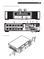
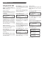
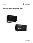
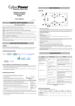
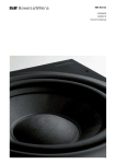
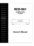
Owner’s Manual
RLC-1040
Power Conditioner
RLC-1040 Power Conditioner
Important Safety Information
WARNING: There are no user serviceable parts inside. Refer all servicing
to qualified service personnel.
WARNING: To reduce the risk of fire or electric shock, be sure that the
apparatus shall not be exposed to dripping or splashing and that no
objects filled with liquids, such as vases, shall be placed on the apparatus.
Do not use this product in an environment where the relative humidity
may exceed 95% (non-condensing).
Do not allow foreign objects to get into the enclosure. If the unit is exposed
to moisture, or a foreign object gets into the enclosure, immediately
disconnect the power cord from the wall. Take the unit to a qualified
service person for inspection and necessary repairs.
2
Inspect the line cords. telephone/data cords, or DSS/Cable TV coaxial cables connected
to this device to ensure they remain fully pushed in or attached, and that they are not
frayed or otherwise damaged.
Immediately stop using the component and have it inspected and/or serviced by a
qualified service agency if:
•
•
•
•
•
The power supply cord or plug has been damaged.
Objects have fallen or liquid has been spilled into the unit.
The unit has been exposed to rain.
The unit shows signs of improper operation
The unit has been dropped or damaged in any way
Place the unit on a fixed, level surface strong enough to support its
weight. Do not place it on a moveable cart that could tip over.
Read all the instructions before connecting or operating the component. Keep this manual
so you can refer to these safety instructions.
Heed all warnings and safety information in these instructions and on the product itself.
Follow all operating instructions.
Unplug this device from the wall outlet before cleaning. Clean the enclosure only with a
dry cloth or a vacuum cleaner. Note: A product that is meant for uninterrupted service
and for some specific reason, such as the possibility of the loss of an authorization code
for a cable TV converter, is not intended to be unplugged by the user for cleaning or any
other purpose, may exclude the reference to unplugging this device.
You must allow 10 cm or 4 inches of unobstructed clearance around
the unit. Do not place the unit on a bed, sofa, rug, or similar surface that could block
the ventilation slots. If the component is placed in a bookcase or cabinet, there must be
ventilation of the cabinet to allow proper cooling.
Keep the component away from radiators, heat registers, stoves, or any other appliance
that produces heat.
The unit must be connected to a power supply only of the type and voltage specified
on the rear panel of the unit. Do not use a plug adapter which defeats the ground pin
of the AC plug.
Connect the component to the power outlet only with the supplied power supply cable
or an exact equivalent. Do not modify the supplied cable in any way. Do not attempt to
defeat grounding and/or polarization provisions. Do not use extension cords.
Do not route the power cord where it will be crushed, pinched, bent at severe angles,
exposed to heat, or damaged in any way. Pay particular attention to the power cord at
the plug and where it connects to the back of the unit. After connecting other devices to
this device, do not push the rear of the device up against any surface (wall or shelving
unit), as this may create an undesired bend in the power cords which may break the
wire strands of the cord.
Although this device provides protection against electrical surges, when connecting an
outside antenna or cable system to devices connected to this device, ensure the antenna
or cable system is grounded so as to provide additional protection against voltage
surges and static charges in accordance with Section 810 of the National Electric Code,
ANSI/NFPA No.70 or later (see illustration).
This device provides a grounding lug at the rear panel for grounding the device to an
external Transient Voltage Surge Suppression (TVSS) device. Ensure this connection is
made in accordance with the instructions provided by the TVSS device.
This device employs Metal Oxide Varisters (MOVs), and other circuitry to protect against
lightning and other sources of voltage surges and sags. It is not necessary to turn this
device or the devices connected to this device, off during a lighting storm.
Do not locate outside antenna systems near overhead power lines, or other electric light
or power circuits, or where it may fall or otherwise come in contact with these power
sources. Do not allow the ladder being used, or the antenna itself to come into contact
with these power sources, as such contact may be fatal.
Do not overload the wall outlet where this device is being connected. Do not overload
this device. Ensure the total load to this device does not exceed that which is listed in the
Specifications section of this manual.
Federal Communications Commission (FCC) Compliance Information
This device complies with Part 68 and Part 15 of the FCC rules. Operation is subject to
the following two conditions: (1) This device must not cause harmful interference, and (2)
This device must accept any interference received, including interference that may cause
undesired operation. As required, the bottom of this equipment contains, among other
information, the Registration Number and Ringer Equivalence Number (REN) for this
equipment. If requested, this information must be provided to the telephone company.
English
3
Front and Rear Panel Controls and Connections
��
��
���
��
�
�
��
�
�
�
�
Rack Ear Mounting
�
�
RLC-1040 Power Conditioner
4
Contents
About Rotel
Important Safety Information ........................ 2
Front and Rear Panel Controls and Connections
3
Rack Ear Mounting
3
About Rotel .................................................. 4
Getting Started ............................................. 4
Features
4
Parts List
5
A Few Precautions ........................................ 5
Power Capacity
5
Placement
5
Front Panel ................................................... 5
FILTERING Status Indicator 1
5
LINE OK Status Indicator 2
5
WIRING OK Indicator 3
5
OVERLOAD Status Indicator 4
5
Backlit LCD Display 5
5
LINE TRIM Status Indicator 6
5
DELAYED ON Status Indicator 7
6
SWITCHED ON Status Indicator 8
6
LINE BOOST Status Indicator 9
6
On/Off Switch 0
6
SETUP Button 6
SELECT Button =
6
Rear Panel.................................................... 6
AC-Power Outlets q
6
Surge Protected COAX/RF Connectors w
6
SYSTEM GROUND Screw e
6
CIRCUIT BREAKER r
6
Input Power Connector t
7
Surge Protected Telephone Jacks y
7
DC TRIGGER Jacks u
7
Installation ................................................... 7
Placement
7
Rack Mounting
7
Making Connections ...................................... 7
Power Input Connection t
7
Turning on the RLC-1040 0
7
Component Connection q e
7
Setting Up the RLC-1040 ............................... 8
Dimmer Function
8
AVR Range Function
8
Delay Time Function
8
Beeper Function
8
Language Function
8
Status and Information Screens ...................... 9
Power Screen
9
Vout / Iout Screen
9
Vin / Freq Screen
9
Serial Number / Firmware Screen
9
Troubleshooting............................................. 9
The RLC-1040 will not turn on.
9
The overload LED is lit.
9
“Wiring OK Indicator” LED is not illuminated.
9
The Line Boost and Line Trim LEDs are flashing.
9
Technical Support
9
Limited Warranty ........................................ 10
Specifications .............................................. 10
A family whose passionate interest in music led
them to manufacture high fidelity components
of uncompromising quality founded Rotel over
40 years ago. Over the years that passion has
remained undiminished and the goal of providing exceptional value for audiophiles and music
lovers regardless of their budget, is shared by
all Rotel employees.
Rotel’s reputation for excellence has been earned
through hundreds of good reviews and awards
from the most respected reviewers in the industry,
who listen to music every day. Their comments
keep the company true to its goal – the pursuit
of equipment that is musical, reliable and affordable.
All of us at Rotel thank you for buying this
product and hope it will bring you many hours
of enjoyment.
Getting Started
Thank you for purchasing the Rotel RLC-1040
Power Conditioner. When used in a high-quality
music or home theater system, your Rotel power
conditioner will protect your high performance
audio and video components from damaging
power surges, spikes and lightning. Protection
is guaranteed. Isolated noise filter banks and
automatic voltage regulation will eliminate power
as a source of audio and video signal degradation. Phone-line surge protection jacks will stop
surges traveling over phone lines.
Digital satellite system, cable modem, and
CATV coaxial cable lines are equally protected.
With the RLC-1040 you can enjoy your home
theater experience with the peace of mind that
performance is optimized and protection is
guaranteed.
Features
• Automatic Voltage Regulation (AVR)
- The RLC-1040 is unique in that it provides
automatic voltage regulation, which is
engaged to correct low and high voltage
conditions. All equipment connected to the
RLC-1040 is protected against these undesired
voltage fluctuations, thus prolonging the life
of the equipment. Low voltage conditions
can also negatively impact video quality.
Consequently this feature may help improve
picture quality if power line voltage is low.
• Surge Protection - The RLC-1040 provides
guaranteed protection against damaging
surges, spikes and even lightning. It not only
provides protection from surges from AC
power lines, it also protects against surges
from system data lines including COAX and
telephone lines. With the RLC-1040 all your
equipment is protected.
• Isolated Noise Filter Banks - The
RLC-1040 eliminates electromagnetic and
radio frequency interference (EMI/RFI) that,
when severe enough, can negatively impact
sound and video quality. Each filter bank
is electrically isolated from each other to
prevent noise generated by one component
from polluting other connected components.
This noise filtering lets your system perform
to its maximum capabilities.
• DC Trigger - When connected to a component that provides a DC trigger, that
component controls the turning on and off
of the ‘delayed’ outlet. The RLC-1040 also
allows that DC signal to pass through to
another connected component.
• Sequenced Turn ON/OFF - This feature
ensures that connected equipment is poweredup/down in the proper order and with the
right amount of delay between the stages.
It allows the user to program a delay into
the sequence of from 0 to 12 seconds. This
delay eliminates transient noises that can
affect connected components.
English
5
• LCD Display - The LCD displays shows
important information including voltage in
(line voltage) and voltage out, frequency,
and load. Additionally, the display is used to
program features such as the delay or dimmer
settings. All information in the display can
be shown in English, French, or Spanish.
• Overload Indicator - The Overload
Indicator lights up if the power requirements
of the equipment connected to the RLC-1040
is too great.
• Removable Support Feet - Feet can be
unscrewed and removed to save space when
the RLC-1040 is rack mounted.
Parts List
The RLC-1040 Power Conditioner includes the
parts listed below. If any items are missing, please
contact your authorized Rotel dealer.
1
1
2
1
2
1
1
1
Power Conditioner
Input Power Cord
Coaxial cables
Telephone cable
Rack-mount ears
User manual
Equipment Protection Policy Sheet
Warranty Registration Card
A Few Precautions
Front Panel
Please read this manual carefully. In addition
to installation and operating instructions, it also
provides important safety information. It is very
important that you have read and understand all
of the safety information located at the front of
this manual. If you have any questions about the
safety information, or are concerned that your
home may not be properly wired for this equipment, please contact a qualified and licensed
electrician.Please contact your authorized Rotel
dealer for answers to any questions you might
have. In addition, all of us at Rotel welcome your
questions and comments.
See the illustration on page 3.
Save the RLC-1040 shipping carton and packing material for future use. Shipping or moving the RLC-1040 in anything other than the
original packing material may result in severe
damage.
Be sure to keep the original sales receipt. It is
your best record of the date of purchase, which
you will need in the event warranty service is
ever required.
Power Capacity
The RLC-1040 Power Conditioner is rated for
1440 watts (continuous). It has been designed,
however, to support current surges that are much
higher than its continuous power rating. The
RLC-1040 is capable of supplying the dynamic
peak current draws required by any component
designed to work on a 15 amp circuit. Despite
their nameplate power ratings, high performance
A/V equipment draw much less than their listed
power ratings. The RLC-1040 can inform the user
how much of the power capacity is available as
equipment is connected to the unit.
Placement
The RLC-1040 weighs approximately 20 pounds.
Keep this in mind when selecting an installation
location. Make sure that the shelf or cabinet can
support its weight.
Proper installation of your new Power Conditioner is important. If the unit is being mounted
in a standard 19” rack, see the Rack Mounting
section of this manual.
FILTERING Status Indicator
1
When lit, this notifies the user that the Electromagnetic Interference/Radio Frequency Interference
(EMI/RFI) noise reduction circuit is active.
LINE OK Status Indicator
2
When lit, this indicates that the voltage from
the wall outlet is within acceptable range. If
this indicator is not lit, the Automatic Voltage
Regulation circuit is active and is correcting high
or low voltage levels to maintain safe voltage
conditions for the connected components.
WIRING OK Indicator
3
When this indicator is lit, the wall outlet the
RLC-1040 is plugged into is properly wired. If
it is not lit one of three wiring problems exists
in the building wiring circuit: missing ground,
overloaded neutral, or reversed polarity. An
electrician should be consulted to resolve the
problem.
OVERLOAD Status Indicator
4
When lit this indicates that the unit is overloaded;
unplug some of the equipment connected to the
unit until the indicator is no longer lit.
Backlit LCD Display
5
Provides status information about the RLC-1040
and the equipment plugged into it. The information in the Display can be shown in English,
French, or Spanish. The brightness of the display
and other front panel indicators can also be
dimmed or even turned off. See the information
in the Dimmer Menu section of this manual.
LINE TRIM Status Indicator 6
When lit, this indicates that the Automatic Voltage
Regulation (AVR) system is engaged to correct
high input voltage conditions.
RLC-1040 Power Conditioner
DELAYED ON Status Indicator
6
7
When lit, power is being supplied to the rearpanel outlets marked Delayed (the Subwoofer and Amplifier outlets).
SWITCHED ON Status Indicator
8
When lit, power is being supplied to rear panel
outlets except those marked Delayed (the
Subwoofer and Amplifier outlets).
LINE BOOST Status Indicator
9
When lit, Automatic Voltage Regulation (AVR)
is engaged to correct low input voltage conditions.
On/Off Switch
0
Controls power to all 12 outlets. We recommend
the unit be left “on” at all times. Control power
to your system and components using their own
controls as you normally would.
SETUP Button
-
This button is used to advance the display through
the various user-selectable set up functions such
as: Dimmer, AVR Range, Delay Time,
Beeper, or Language.
SELECT Button
=
This button is used to select the setting you want to
use in the various setup functions such as: Dimmer, AVR Range, Delay Time, Beeper, or
Language. It is also used to access the Status
and Information Screens.
Rear Panel
See the illustration on page 3.
AC-Power Outlets
q
The RLC-1040 Power Conditioner provides for
connection of up to twelve components. The outlets
are arranged according to the type of filtering
protection provided for a given component type.
These Isolated Noise Filter Banks (INFBs) eliminate
EMI and RFI that can negatively impact sound and
video quality. You should plug your components
into the recommended outlets to achieve optimum
protection for your equipment.
Note: All outlets provide surge protection,
voltage protection and noise filtering.
DIGITAL FILTER Outlets eliminate noise
interference for Digital Components (CD, DVD,
DVR, CATV/SAT, Flat Panel Monitors, Hi-Def
tuners, etc.).
Note: Any digital device can be plugged into
the DIGITAL FILTER outlets, any video device
can be plugged into either of the VIDEO FILTER
outlets, etc. For example, if you have a cable
box and a satellite receiver, but no monitor, you
can plug the cable box into the “CATV/SAT”
outlet, and the satellite receiver into the “Monitor” outlet.
VIDEO FILTER Outlets provide filtering for
video devices (TV and VCR).
ANALOG FILTER Outlets provide filtering
for analog-based equipment (TUNER/AUX
and Preamp/Receiver).
HIGH CURRENT FILTER Outlets provide
filtering for high-current devices (SUBWOOFER
and AMPLIFIER).
Surge Protected COAX/RF
Connectors w
The surge protection feature prevents surges
traveling over coaxial data lines from damaging
the system. Connect the coaxial cable from the
CATV or Cable Modem provider to the connector
marked “IN”, connect other cables from the
connectors marked “OUT” to the device(s)
being protected (CATV box or Cable Modem).
The RLC-1040 has an internal cable splitter so
a single cable input can provide signals to two
components.
The RLC-1040 also provides the same surge
protection for your satellite or RF antenna system. Connect the coaxial cable from the satellite
or antenna system to the connector marked
“IN”, connect another coaxial cable from the
connector marked “OUT” to the device being
protected.
SYSTEM GROUND Screw
e
Provides for the connection of grounding wires
from all of your equipment. Grounding all your
equipment to a single terminal prevents “ground
loop” problems that can cause a “hum” to be
heard through the speakers.
CIRCUIT BREAKER
r
This “press-to-reset” Circuit Breaker may be
“tripped” when there is a power line surge or
when the unit is overloaded. If such conditions
occur the circuit breaker button pops out and
shuts down output power to the outlets. To reset
the Circuit Breaker simply push the button in.
Caution: When resetting the Circuit Breaker,
push the button in quickly and release it. Do not
hold the Circuit Breaker button in. Doing
so may result in equipment damage.
English
7
Input Power Connector
t
Provides for connection of the supplied AC power
cord to the RLC-1040. Connect the other end to
a normal AC power outlet (15 Amp, 120 VAC,
50-60 Hz).
Surge Protected Telephone Jacks
(TEL/DVR/SAT/DSL) y
The RLC-1040 has a telephone line splitter with
surge protection for components connected via
telephone line. Connect the supplied RJ11 telephone cable from the wall jack (source) to the
telephone line connector marked “IN”. Connect
the telephone cables from the connectors marked
“OUT A” and “OUT B” to the equipment to be
protected (Telephone, DVR, DSS or DSL).
DC TRIGGER Jacks
u
When the DC Trigger “IN” jack is connected
to a component that provides a DC trigger,
that component controls the turn on/off of the
“delayed” outlet banks. The DC Trigger “OUT”
jack provides a DC signal output that can be
connected to another component.
Caution: When making connections to the
DC Trigger jacks, connect the source of the
DC Trigger to the IN jack. The OUT jack
should be used only as a pass-through. The
DC Trigger signal can be short circuited if the
input and output cables are reversed.
The maximum input voltage for the DC Trigger
is 30VDC. Do not apply an AC voltage to the
DC Trigger jacks. Failure to comply with
this statement may result in equipment damage.
Installation
Making Connections
Placement
Power Input Connection
Place the unit on a solid, flat surface that is
capable of supporting at least 20 lbs.
Note: Avoid placing other components directly on top of or behind the unit. Leave at
least one inch of space on all sides to allow
for proper air ventilation.
Rack Mounting
Caution: Be sure to support the RLC-1040
until it is firmly mounted in the equipment
rack. This process may require two people.
The RLC-1040 can be mounted in a standard 19”
rack. Rack-mounting ears and screws to attach
them to the RLC-1040 are provided.
1. Install the rack-mount ears. See the illustration on page 3. The holes in the rack ears
for the mounting screws are slotted. This
allows some front-to-back position adjustment when the unit is mounted in the rack.
Note that even with the rack ears mounted
as far back as they can go, the front of the
RLC-1040 will protrude about 1” from the
front of the rack.
2. Position the RLC-1040 in the equipment rack
so the rack mount ears are against the rack
side rails.
3. Align the holes in the rack ears with the holes
in the rack side rails. Install the rack mounting
screws.
t
Connect the AC Power Cord to the rear panel
power INPUT t. Plug the other end into a wall
power outlet. Whenever the RLC-1040 is plugged
into an AC power source, its microprocessor is
active and the unit monitors the input power.
When the unit is first plugged in, it will be in a
“STANDBY” state – the front panel display and
indicators are not illuminated and the rear panel
power outlets are off.
Turning on the RLC-1040
0
To turn on the RLC-1040 push the front panel
Power Switch 0 in all the way then release
the switch. Once power is applied to the unit,
the LCD shows the Voltage In/Voltage Out
display.
������������������
������������������
Note: In the display shown above, the input and
output voltages are the same. The actual voltage
may vary depending on the power supplied by
the local utility. In this case, both voltages are
within acceptable ranges so the RLC-1040 does
not have to “clean up” the output voltage.
Normally once the RLC-1040 is turned on there
is no reason to “turn it off”, that is return it to
STANDBY mode. It can remain connected and
active at all times.
Recovery From a Power Failure
If there is a power failure while the RLC-1040 is
on, the unit will automatically turn itself back on
when power is restored. If it is in “STANDBY”
when a power failure occurs, it will remain in
“STANDBY” when power is restored.
Component Connection
qe
The RLC-1040 has four groups of power outlets
q. Each group has specialized filtering and
surge protection that are specifically designed for
certain types of components. It is recommended
that the A/V components be connected to the
power outlets designed for that type of unit.
For more information see the AC Power Outlets
section of this manual.
Connect the ground connector of each component
in the system to the SYSTEM GROUND terminal
e on the RLC-1040. This will help prevent any
“ground loop” problems which can cause “hum”
to be heard through the speakers.
RLC-1040 Power Conditioner
Setting Up the RLC-1040
Use the front panel Setup and Select buttons
- = to configure the various features and
functions of the RLC-1040
Dimmer Function
This function sets the brightness level of the front
panel LCD Display and the LED indicators. Press
the Setup button once to access the Dimmer
Function display.
8
Wide AVR Range – Takes input voltages
from 92-145 VAC and regulates it to 120 VAC
± 15%. Use this setting if the power input voltage
has large variations
The “Vin” line of the “Voltage Input/Output”
display (see preceding page) will show you how
much the input voltage varies.
Press the Setup button until the “SET AVR
RANGE ?” menu is displayed.
������������������
������������������
������������������
������������������
Once the display is shown, repeatedly pressing
the Select button allows you to set the brightness
of the display. The brightness level can be set to:
Off, Dim 3, Dim 2, Dim 1, Normal, Bright 1,
Bright 2 and Bright 3. Once the Display brightness is at the desired value, press the Setup
button to store the setting.
Then press the Select button to change the AVR
Range setting. After you have selected the AVR
Range setting you want, press the Setup button
to accept the setting.
AVR Range Function
Allows you to adjust the AVR (Automatic Voltage
Regulation) system of the RLC-1040. It can be
set to: Narrow, Normal or Wide.
Narrow AVR Range – Takes input voltages
from 100-132 VAC and regulates it to 120 VAC
± 5%. Use this setting if the power input voltage
is fairly stable.
Normal AVR Range – Takes input voltages
from 97-139 VAC and regulates it to 120 VAC
± 10%. Use this setting if the power input voltage
has moderate variations
Delay Time Function
This function sets the amount of time that elapses
before the RLC-1040 provides power to the rear
panel outlets marked Delayed. The same amount
of time will elapse before the RLC-1040 removes
power to the Delayed outlets.
Press the Setup button until the “SET DELAY
TIME ?” menu is displayed.
������������������
������������������
Then press the Select button to select the amount
of delay - from 0 to 12 seconds). Press the Setup
button to store the setting.
Beeper Function
This function turns the beeper sound on or off.
When the beeper sound is on, each press of the
Setup or Select button will be accompanied
by a beep.
Repeatedly press the Setup button to advance
to the “SET BEEPER ?” menu.
������������������
������������������
Press the Select button to toggle the beeper
between ON and MUTE. Press the Setup
button to store the setting.
Language Function
This lets you select the language for the LCD
display. Repeatedly press the Setup button to
advance to the “SET LANGUAGE” display.
������������������
������������������
Press the Select button to select the language
– English, French or Spanish.
������������
������������������
������������
������������������
������������
������������������
Press the Setup button to store the setting.
English
9
Status and Information
Screens
The RLC-1040 LCD display can show four Status
and Information screens – Power, Voltage/Current Output, Voltage/Frequency Input and Serial
Number/Firmware Version. These screens are
accessed by pressing the Select button (without
first pressing the Setup button).
Power Screen
The Power display shows the amount of power
being used by the components connected to the
RLC-1040 and how much of its power capacity
(as a percentage) is being used.
������������������
������������������
Vout / Iout Screen
Pressing the Select button again will display
a screen that shows the voltage output of the
RLC-1040 and the amount of current being used
by the components attached to the unit. Note:
“Iout = X.X A” is the current output.
������������������
����������������
Vin / Freq Screen
Pressing the Select button again will display
a screen that shows the input voltage and
frequency .
������������������
����������������
Serial Number / Firmware Screen
Pressing the Select button again will display
a screen that shows the Serial Number of the
unit and the current Firmware Version. This
information may be required if you need to
contact Technical Support or if you need to
make any Warranty or Equipment Protection
Policy claims.
����������������
����������������
Troubleshooting
This section describes possible causes and
solutions.
The RLC-1040 will not turn on.
Probable Cause: Input power cord is not
connected properly.
Solution: Ensure supplied power cord is connected firmly at both ends.
Probable Cause: No power or insufficient
power available at the wall outlet.
Solution: Ensure the wall outlet has good
power by using a voltmeter, or by plugging in
another device.
Note: The unit will not turn on and accept incoming utility power if the power is out of range.
Probable Cause: Circuit Breaker has
tripped.
Solution: Check both home and unit circuit
breakers. If the circuit breaker located on the
rear of the RLC-1040 has tripped, the center post
will extended outwards. Push it back in to reset
it. If the trip occurs again, reduce the amount of
equipment plugged into the unit and try again.
While the unit’s breaker is rated for 15 Amps,
National Electric Code (NEC) dictates that any
particular home circuit should not be loaded
more than 80% of its rating.
The overload LED is lit.
Probable Cause: Unit was overloaded.
Solution: There is an “Overload” LED on the
front display panel which will light ‘red’ if the
unit is overloaded. If the unit is overloaded or
nearly overloaded (>95%), reduce the load by
unplugging one or more components.
“Wiring OK Indicator” LED is not
illuminated.
Probable Cause: There are 3 reasons why
this LED would not be illuminated:
1. Reversed polarity exists at the wall outlet.
2. Neutral wire is overloaded.
3. Earth ground is missing at the wall outlet.
Solution: Operating the unit under such
conditions may impact its surge protection
performance. Contact an electrician to have
them inspect the building or home wiring to fix
the problem.
Probable Cause: Unit is on but LEDs are
turned off.
Solution: Push the Setup button to access the
“SET DIMMER” screen. Then press the Select
button to turn on the LEDs and set the brightness
level you want.
The Line Boost and Line Trim LEDs
are flashing.
Probable Cause: One of the relays (electrically
controlled switches) in the RLC-1040 is stuck.
Solution: Disconnect the power input cord and
then plug it in again. If the problem remains,
contact APC.
Technical Support
If the problem remains unsolved con t a c t R o t e l Te c h n i c a l S u p p o r t a t
800-370-3741.
RLC-1040 Power Conditioner
10
Limited Warranty
Specifications
Rotel warrants this product to be free from
defects in materials and workmanship for a
period of five years from the date of purchase.
Its obligation under this warranty is limited to
repairing or replacing, at its own sole option,
any such defective products. To obtain service under warranty contact your authorized
Rotel dealer or Rotel Technical Support at
800-370-3741.
INPUT
Number of Outlets
12 (all outlets are surge protected, conditioned
If a product has to be returned for service you
must include with the following:
• Prepaid transportation charges
• Brief description of the problem encountered
• Proof of date and place of purchase
Output Regulation
±5% for Narrow Range AVR
Input Voltage Range for Operation
92V - 145V
Nominal Voltage
120 Vac
Allowable Input Frequency for Operation
47 - 63 Hz
Rated Input Current
12 Amps
Input Circuit Breaker Rating
15 Amps
OUTPUT
and regulated)
This warranty does not apply to equipment that
has been damaged by accident, negligence, or
misapplication or has been altered or modified in
any way. This warranty applies only to the original purchaser who must have properly registered
the product within 10 days of purchase.
EXCEPT AS PROVIDED HEREIN, ROTEL MAKES
NO WARRANTIES, EXPRESSED OR IMPLIED,
INCLUDING WARRANTIES OF MERCHANTABILITY AND FITNESS FOR A PARTICULAR
PURPOSE. Some states do not permit limitation
or exclusion of implied warranties; therefore,
the aforesaid limitation(s) or exclusion(s) may
not apply to the purchaser.
EXCEPT AS PROVIDED ABOVE, IN NO EVENT
WILL ROTEL BE LIABLE FOR DIRECT, INDIRECT,
SPECIAL, INCIDENTAL, OR CONSEQUENTIAL
DAMAGES ARISING OUT OF THE USE OF THIS
PRODUCT, EVEN IF ADVISED OF THE POSSIBILTY
OF SUCH DAMAGE. Specifically Rotel is not liable for any costs, such as lost profits or revenue,
loss of equipment, loss of use of equipment, loss
of software, loss of data, costs of substitutes,
claims by third parties, or otherwise.
±10% for Normal Range AVR
±15% for Wide Range AVR
Outlet type
NEMA 5-15R
Rated VA Capacity
1440VA
Rated Watt Capacity (continuous)
1440 Watts
Rated Output Current
12 Amps
SURGE PROTECTION
Let-Through Voltage Rating
<40 Volts
Peak Surge Current (NM + CM)
250KA
Data Line Protection Jacks (splitter)
Single-line 2-wire phoneline protection for phone,
Coax
5MHz-1GHz Two pairs (one with splitter)
modem, or fax.
MISCELLANEOUS
EMI/RFI Attenuation
40-100dB at 100KHz-30MHz
Total Surge Joules
5200 Joules
DC Trigger
Two 3.5mm mini-jack plugs (5-30VDC)
Physical Dimensions (H x W x D)
3.75 x 17 x 10.1”
Unpackaged Weight
20 lbs.
Shipping Weight
25.4 lbs.
Safety Agency Approvals
UL1449, cUL, FCC Part 68 and Part 15 Class B,
NOM
All specifications are accurate at the time of printing.
Rotel reserves the right to make improvements without notice.
The Rotel Co. Ltd.
10-10 Shinsen-Cho
Shibuya-Ku
Tokyo 150-0045
Japan
Phone: +81 3-5458-5325
Fax: +81 3-5458-5310
Rotel of America
54 Concord Street
North Reading, MA 01864-2699
USA
Phone: +1 978-664-3820
Fax: +1 978-664-4109
Rotel Europe
Dale Road
Worthing, West Sussex BN11 2BH
England
Phone: + 44 (0)1903 221 761
Fax: +44 (0)1903 221 525
Rotel Deutschland
Vertrieb: B&W Group Germany GmbH
Kleine Heide 12
D-33790 Halle/Westf., Deutschland
Tel.: 05201 / 87170
Fax: 05201 / 73370
E-Mail: [email protected]
www.rotel-hifi.de
www.rotel.com
082 OMRLC 1040 032306
English