1
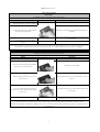
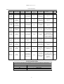
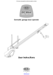
UMPETHA U 082009/072010.012 Domestic sliding gate operator by ET SYSTEMS. USER GUIDE 1 UMPETHA U 082009/072010.012 Table of contents Page 3 Description Safety obligations and general warnings M anual ov erride 3 How to mov e the gate by hand. Manual override Operating mode options. 4 Standard mode 4 Simple auto-close mode 4 Condominium mode 4 PIRAC auto-close mode 4 Courtesy light functionality 5 Pedestrian operation 5 Safety sensing system. M aster remote functions and additional features 6 Registering a transmitter using the master remote 6 Auto-close ov erride/party mode 7 Holiday lock-out Trouble shooting 7 Status LED indication guide 8 Buzzer indications 8 Warranty Glossary of terms used in this manual. BT PD or PED BM Button trigger or full operation trigger for v ehicle access. Pedestrian operation trigger Safety infra-red beam set for the detection of objects in the path of the gate. TX Remote transmitter / remote control RX Radio receiv er for remote transmitters LED Condo (Light emitting diode) visual light i ndicator Condominium or Complex mode A metal detector loop (antenna) for the Loop detection of motor v ehicles installed in the drivew ay surface. 2 UMPETHA U 082009/072010.012 GENERAL SAFETY OBLIGATIONS TO THE INSTALLER AND END USER. Caution! It is important for personal safety to follow all the instructions carefully. Incorrect installation or misuse may cause serious personal harm. Keep the instructions in a safe place for future reference. This product was designed and manufactured strictly for the use indicated in this documentation. Any other use not expressly indicated in this documentation, may damage the product and/or be a source of danger. We accept no responsibility due to improper use of this product. Care must be taken not to install this product in an unsafe environment. I.e. near inflammable gases and or fumes. We will not accept responsibility if the principles of good workmanship are disregarded by the installer. The construction of the gate must be sound and automatable. It is the responsibility of the installer to ensure that all mountings to the gate are sufficient to withstand the necessary forces in cases of overload. Before carrying out any work on the product, ensure that the electrical supply is switched off. It is highly recommended that a set of safety infra red beams be used in conjunction with this product. We accept no responsibility regarding safety and correct operation of the automation if other manufacturer’s equipment is added to this product. Do not make any modifications or alterations to this product. It is the responsibility of the installer/ service provider to completely instruct and demonstrate the proper use of this product, especially the emergency override, to the end user. It is also the responsibility of the installer/ service provider to issue all end user documentation, which accompanies this product, to the end user. It is the responsibility of the installer to instruct the end user on the proper maintenance of the operating system and it components. i.e. The clearing of gravel from the track, testing the manual override regularly, testing the gate travel manually for variance in load.........etc. Ensure that other persons, especially children are clear of the gate and opener before and during operation. Keep remote transmitters away from children to prevent accidental activation of the system. The end user should refrain from attempting to make any repairs or adjustments to the system and should contact professional qualified assistance timorously. Anything other than expressly provided for in these instructions is not permitted. The electrical supply to this product must comply with the local electrical code of practice and any electrical work must be carried out by a qualified electrician. Over and above the recommendation to use safety infra red beams with this product it is mandatory to ensure a set has been installed and is in proper working condition when using the automatic closing feature. Manually overriding the gearbox to be enable movement of the gate by hand. Locked and engaged Unlocked and engaged Insert key and turn clockwise. Unlocked and disengaged Turn override cam anti-clockwise The manual release in the open position also deactivates the electronic control. To operate the unit normally the release door must be fully closed. Remember to gently push or pull the gate until the gearbox re-engages before running the motor. The gears will lightly click into place. 3 UMPETHA U 082009/072010.012 OPERATING MODE OPTIONS. For further information about how your UMPETHA has been configured please refer to your service provider/installer. Standard (Four step logic) Mode When the motor is activ ated using any BT input the gate w ill open or close and can be stopped in mid cycle using any BT input again. The gate can then be rev ersed by a ctiv a ting the BT input again. In this mode the gate w ill remain open w here it has been stopped either by button or open limit until the BT input is activ ated a ga in. (No auto close) Party mode is av aila ble in this mode. (See additional fea tures below ) Holiday lock out is av ailable in this mod e. (See additiona l features below ) M aster remote p rogramming is av ailable in this mode. Simple Auto-close Mode As per Standard mode abov e howev er the following differs: The unit times out the pre-programmed auto-close time from any open position after which it begin closing the gate. While closing the gate any BT or BM input will stop and rev erse the motor direction back towards the full open position. In any open position while auto-close is timing out a BM input will reset the auto-close timer. Auto-close ov erride/Party mode is av ailable in this mode. (See additional features below ) Holiday lock out is av ailable in this mode. (See additional features below) M aster remote programming is av ailable in this mode. ) Mode Complex Auto-close (selected when using a loop detector) In this mode any BT input trigger is treated as an opening trigger. On reaching the full open position the unit times out the pre-programmed auto-close time after which it will begin closing the gate. If the BM or BT input is activ ated w hile the auto-close timer is running the time w ill simply reset. On closing any BT input or BM input will re-open the gate to the full open position. USE THIS MODE WHEN CONECTING A LOOP DETECTOR. This mode excludes Holiday lock-out, Auto-close ov erride/Party mode and M aster remote programming. P.I.R.A.C. Auto-close Mode In this mode the unit w ill operate as per Simple auto-close abov e. The added feature here is quick closing once the BM input has been activ ated and cleared. I.e The gate is opening; a car enters the beams and passes right through. The BM input is now clear again and the gate immediately closes. If the gate reaches the full open position the pre-programmed auto-close timer times out after which the gate w ill begin closing. This mode includes Holiday lock-out, Party mode/auto-close ov erride and master remote programming except when used in conjunction with Complex auto-close mode. Courtesy light out Activ e in all operating modes. The courtesy light output w ill activ ate on any opening trigger (BT or Pedestrian). The light output w ill remain activ e until the gate has re-closed. It w ill sw itch off 3 minutes after the gate has closed. 4 UMPETHA U 082009/072010.012 P edestrian opening Available in all modes. Action 1. Response Gate in closed position A) 3 x 1sec beeps after w hich gate opens to pedestrian opening position. 2. Press and release any PED B) At pedestrian opening position (pedestrian) input. pedestrian auto-close timer times out. C) 3 x 1sec beeps after w hich gate recloses. Any further PED (pedestrian) input triggers w hile the gate is running are ignored except in the pedestrian opening position, w here the auto-close timer w ill simply reset. Any BM (beam) input w hile the pedestrian routine is running w ill cause the gate to continue to the p edestrian opening position or rev erse back to the pedestrian opening position. If already in the pedestrian op ening position, the auto-close timer w ill simply reset. Any BT (full opening input w hile the pedestrian routine is running w ill open the gate to the full op en position and the unit w ill rev ert to the operating mode selection that has been setup. INHERENT SAFETY SENSING SYSTEM Collision/obstruction/hindrance while opening. (All modes) If a collision, obstruction or hindrance is encountered before the full open position is reached while opening, the gate will stop, back off and wait for the next trigger input before closing slowly. The status LED will flash rapidly while stationery after backing off of collision. Closing trigger clears LED indication. Collision/obstruction/hindrance while closing. (All modes) If a collision, obstruction or hindrance is encountered while closing, the gate will stop and reverse to the fully open position. The next trigger input start the gate closing slowly. The status LED will flash rapidly while stationery after backing off of collision. Closing trigger clears LED indication. Multiple collision/obstruction lock-outs. (All modes) On encountering 4 consecutive obstructions while closing the gate, the UMPETHA will not reverse back to the full open position. The response will be a 5 sec beep tone, followed by a gentle momentary reverse away from the obstruction. The unit will now begin a mandatory 30sec lockout whereby the only response to any trigger input will result in a tone so long as the trigger button is held. After 30sec a trigger input will result in a repeat of the 5 sec beep and the gate opening 1 meter or to the full open position whichever is reached first. The unit will once again lock out. This time the user must manual release the unit and test the travel by hand before attempting any further automation of the gate. The Status LED will flash rapidly throughout this procedure indicating an obstruction has occurred. Releasing the gearbox and re-engaging it will clear the LED status and the Collision lock out routine. Collision with closed stopper due to faulty or missing closed limit. (All modes) If no limit input is made when expected (as calculated by the programmed run time) the UMPETHA will not reverse back to the open position as it normally would when obstructed. It will however stop at the point of impact with the closed catch and emit a 5sec long beep tone. At the next valid opening trigger the UMPETHA will re-emit the 5sec long beep tone and only open the gate by ±1 meter. This will allow for the user to be able to enter the property and manually override the gate. The magnet actuator and limit can now be checked. If not corrected and further attempts are made to operate the UMPETHA with a faulty closed limit condition the same routine will be repeated on every operation. If the user continues to attempt to operate the gate without manually releasing the gearbox while the gate is at the ±1meter position, the result will only be a repeat of the 5sec beep tone. 5 UMPETHA U 082009/072010.012 REGISTERING ADDITIONAL REMOTE USERS ON YOUR UMPETHA. Learning a TX button for BT (Full opening) operation using the RX Master remote: - (25 user memory) The RX M aster remote can only be learnt into memory using the RX pins! The RX M aster remote is the first remote learnt into the BT memory and it must be able to operate the PED function of the built-in RX as w ell. Feature not av ailable in Condo/loop mode Feature limited to learning in BT operation transmitters only. Action Response 1. Open gate fully using the G ate runs to full open position and RX master remote stops 2. Press and hold RX M aster Start of 5sec. Beep. W aiting for new remote pedestrian button. remote trigger. 3. Release RX M aster remote Continues to beep. pedestrian button Long beep changes to..... 4. Press and hold required 2 beeps = Successful there is still memory button on new TX before av ailable learn mode timer expires and beep stops. M ultiple rapid beeps = memory full No beep = Button already in RX memory or non ET Blue TX used. To continue adding remotes repeat from point 2. If no new TX button is pressed w ithin 5sec. Of the continuous beep beginning, then the RX w ill exit learn mode. All other functions return to normal. For additional master remote transmitters or Pedestrian control transmitters contact your service provider/installer. 6 UMPETHA U 082009/072010.012 Auto-close override P arty mode Av ailable in all but Complex Auto-close mode. Action Response 1. With the gate at any open position 2. Press and hold any TX (transmitter) BT (full opening) button 3. 4. After 5sec unit will emit Multiple rapid beeps to confirm. Release input after beeps Gate will not begin closing after auto-close time has expired. To deactiv ate repeat 2 and 3 abov e 1 x long beep and gate starts closing. If any PED (Pedestrian) or BT (full opening) input is momentarily activ ated while the unit is in either Holiday lock-out or Auto-close ov erride/Party mode the unit will only emit the multiple rapid beeps and not run the gate. Holiday lock-out Av ailable in all but Complex Auto-close mode. Action 1. 2. Response Close gate Press and hold the PED (pedestrian) U ntil 5sec beep begins. button on a master remote 3. Release PED (pedestrian) button on Beeping w ill continue until confirmation or 5sec master remote 4. expires. Press and release BT (full opening) 1 x multiple rapid beeps w ill confirm holiday lockout is activ e. button on the master remote before 5sec beep stop. After multiple confirmation beeps gate w ill To unlock repeat immediately start opening w hen unlocked. Holiday lock-out is av ailable only w hen using a master remote. (No hardw ired dev ices w ill activ ate) A master remote is a remote that has BT (full opening) control as well as PED (Pedestrian) opening control. If no BT (full opening) confirmation trigger is receiv ed by the time the intermittent beeps stop (5sec.), the gate w ill not change status. 7 UMPETHA U 082009/072010.012 Buzzer indications Beeps Gate status Program Jumper Action Response Motor Condition 5 x Rapid beeps Full closed Off Momentary BT or Ped input None Holiday lockout active Toggle off pg 26 Continuou s rapid beeps Gate anywhere On None None Holiday lockout active Toggle off pg 26 5 x Rapid beeps Gate anywhere but closed Off Momentary BT or Ped input None Auto-close override/part y mode active Toggle off pg 27 1 x 5sec beep (long beep) opens 1m and remains there. Off Momentary BT or Ped input None limit failure check magnet on gate and limit switch pg 20 Solution Table ref: Allow recharge and check for Aux Battery flat or devices overload. If faulty problem persists after ±8 hours charging, replace battery 2 x Rapid beeps Gate anywhere Off or On Momentary BT or Ped input Attempts to run 3 x 1sec. Beeps Gate closed Off Momentary Ped Gate opens partially Pedestrian function activated 2 x 2sec. Beeps Gate stopped Off Momentary BT Gate runs Household mains failure Restore power supply 1 x 5sec beep (long beep) Gate stopped Off Any input triggered None Multiple collision lockout Check gate closing resistance pg 20 None No motor movement detected or beam input is active Check beam circuit or setting. Check gate resistance. Check motor and battery wiring/looms. pg 19, 20 &14 20 x 1sec. Beeps. Gate stopped First BT input after a reset or Off or On Set button in runtime set up pg 27 STATUS LED INDICATIONS. An extension LED needs to be installed for the end user to make use of this f eature. Of f Gate closed Slow flash Gate is running or w aiting for auto-close time to time out On Gate is open Rapid Flash Gate is obstructed or has exceeded max run time. 8 UMPETHA U 082009/072010.012 WARRANTY: All goods manufactured by G&C Electronics cc T/A ET Systems carry a 12 month factory warranty from date of invoice. All goods are warranted to be free of faulty components and manufacturing defects. Faulty goods will be repaired or replaced at the sole discretion of ET Systems free of charge. This warranty is subject to the goods being returned to the premises of ET Systems. The carriage of goods is for the customers account. This warranty is only valid if the correct installation and application of goods, as laid out in the applicable documentation accompanying said goods, is adhered to. All warranty claims must be accompanied by the original invoice. All claims made by the end user must be directed to their respective service provider/installer. The following conditions will disqualify this product from the warranty as laid out above. These conditions are non-negotiable. • Any unauthorized non-manufacturer modifications to the product, components thereof. • Variations to the installation technique as laid out here-in • Incorrect application and use of the product. The following are excluded or limited from the warranty as laid out above. These conditions are non-negotiable. • The battery carries a limited 6 month warranty • The motor brushes • Acceptable wear and tear. 9