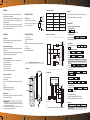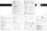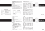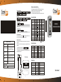
1
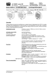
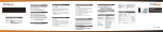
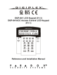
Resetting to factory default setting To add users continuously st n d rd Press manager's add fingerprint 1 user fingerprint 2 user fingerprint 3 user th fingerprint ...... N User Fingerprint Manager's add fingerprint When add user, the fingerprints ID number will auto add from 3~120. To delete users Press manager's delete fingerprint 1st user fingerprint 2nd user fingerprint 3rd user fingerprint ...... Nth User Fingerprint Manager's delete fingerprint Reliable. Durable. Affordable 3 Delete all fingerprints Press * manager password # 20000 Note: This will delete all fingerprints, including Manager Fingerprint, before this operation you need make sure the data is unuseful. 4 Setting open door time Press * manager password # 4 XX Note : Open door time is the lock keeps time. XX 0-10s , default setting 5s. Turn off the power, press the reset key(SW1) on the PCB, keep holding it and re-power the device, SB-7500 will give three short beeps, means reset to factory setting successfully,then move more your finger off from the reset key. It is to revert all settings to the factory default setting, but the users' data enroled is safe. Sounds and light status Operation Status Red led Green led Blue led Buzzer Resetting Bright Bright Goes out Consecutive short ring Power on Slow flashing Goes out _ Short ring Sleeping status Slow flashing Goes out Goes out Stay status Slow flashing Goes out Quickly flashing Enter programme status Bright Goes out Goes out Programme status Bright Goes out Goes out Bright Simplified Instruction Function description Choose from the relevant functions below and input *-9999 - #, Enter the programming mode then you can do the programming (9999 is the default factory master code) change the master code Add user Delete user Exit from the programming mode 0 - new code - # - repeat the new code - # (code: 4 digit) 7-Fingerprint -repeat Fingerprint - # (can add Fingerprints continuously) 8- Fingerprint - # (can delete Fingerprints continuously) SW2 Tamper switch PCB connect diagram SW1 Reset switch Three short ring Long ring Exit programming status Open door status Goes out Bright Goes out alarming Quickly flashing Goes out Quickly flashing Consecutive long ring Note: means keep plain state. Supply Voltage 12VDC User fingerprint quantity 118 Sleeping Current <20mA Resolution 450 DPI Stay Current <100mA Fingerprint input time <1S Door Relay 3A Identification time <2S Temperature -20 Humidity 10% FAR <0.0001% 20%RH-95%RH FRR <0.01% Memory capacity 120 Dimensions 115mm 70mm Manager quantity 2 weight 500g -55 Descriptions Model no. Fingerprint & Door Access machine F007 Quantity OPEN 12V GND NO COM NC 12V 35mm .5. Remark 1 1 User Manual F007 Security Screws 3mm 1 7.5mm 1 Screw driver Used for front case and back case 1 Self tapping screws 4mm 25mm 4 Used for fixing Pastern stopper 6mm 25mm 4 Used for fixing OPEN NC NO GND COM Wiring Cable Hamess Long ring Technical Specification Infrared remote control keypad Put the Finger on the fingerprint sensor for 1 second .4. Long ring Input fingerprint fail Package Listing * How do release the door Fingerprint User Short ring Quickly flashing Input fingerprint success 6 Manager release alarm When this machine is in stay status if it was be opened, the buzzer will sound consecutive long ring. A nd it Will be keep on 1 minute. While it in the alarm status you can use either of the follow ways release alarm. a.Use Infrared remote control keypad, input alarm release password. # (the release password is the same with manager password.) b.Use manager fingerprint, press mangers' fingerprint, either manager add fingerprint or manager delete fingerprint is ok. CFX-SB-7500 Stand Alone Biometric Reader Short ring Voided key Input fingerprint instruct 5 Exit programming mode to exit from p rogramming mode. If no press When the operation is over, you can press but over 1 minute, it will exit from programming mode automatically.. Reliable. Durable. Affordable .6. User manual Introduction Terminal wire connector function SB-7500 use the precise electron circuit and good productive technology, which is the metal structure fingerprint & access machine. This machine uses the most advanced fingerprint identification technology, very safety. Which is the most ideal choose. It is widely used in business affairs organization, office, factory, housing district etc. This product's programming is done by the infrared remote control keypad or fingerprint manager. This product maximum can store 120 fingerprints. There are 2 fingerprint managers, and each fingerprint has one ID code. Intramural interface circuit Specifications Install Sleeping function When this machine in stay status, it will auto enter sleep status.This can reduce power dissipation and prolong the machine's use life. 1 Drill 4 holes on the wall 2 Thread the cable through cable hole 3 Wiring 4 When wiring completed, attach the rear plate to the wall firmly with at least three flat head screws 5 Plug the cable harness 6. Attach the front cover to the rear plate Relay NO GND Black Gnd NO Blue Relay output NO Electric lock interface wiring and fixation COM Purple Relay output COM NC Orange Relay output NC Common powers connects diagram OPEN Yellow Open door button +12V Red +12V GND Black GND +V -V Orange GND PUSH +12V GND Open door button Fingerprint Sensor Red Black +V -V + - Power on the locks keep opening Important information If holes are to be drilled before mounting onto a wall, check for hidden cables and/or pipes before drilling. Use safety goggles when drilling or hammering in cable clips. Every effort has been made to provide accurate information, however slight variations can occur. We also reserve the right to make changed for product improvement at any time. + - OPEN +12V GND V+ Blue V- Off power the locks keep opening Purple Orange NO .3. 2.3 By Manager fingerprints In programming mode, Press 1 1 input fingerprint twice 2 fingerprint twice * ID number 1: Manager add fingerprint ID number 2: Manager delete fingerprint The first Fingerprint: Manager add Fingerprint, it is to add the users The second Fingerprint: Manager delete Fingerprint, it is to delete users input another COM To add one user: NC Press Manager add Fingerprint Input User Fingerprint twice Repeat Manager add Fingerprint Note: We advise you use special adaptor, it will make your system work more stable. .2 . 2 Add and delete Users There are 3 ways to add and delete user, 1, by keypad;; 2, by User ID;; 3, by Manager Fingerprint 2.1By keypad (the most convenient way) Add User * manager password # 7 input fingerprint twice # * (to add more than one user, just input finger continuously) Delete User * manager password # 8 input fingerprint once # * (to delete more than one user, just input finger continuously) NC 12V special power supply Yellow 1 Manager mode (using Infrared remote control keypad) 1.1 Enter programming mode Press * manager password # Manager password: 9999 ( factory default setting) 1.2 Changing manager code In programming mode, Press 0 new password code # Repeat new password code # The manager code must be 4 digit number Note: When add fingerprint, please put the Fingerprint which you will add on the sensor twice, during which the light shines red then turn green, means the Fingerprint is added successfully. when delete users, just input fingerprint once. Special power supply Infrared Sensor Operation guide 2.2 By User ID To add one user: * Manager password # 1 ID number # Input user Fingerprint twice # * (User ID number can be any digit between 3- 120, but one ID number to one user.) To add users continuously * Manager password # 1 3 # 1st User Fingerprint 4 # 2 nd user fingerprint...... N # Nth user fingerprint # * To delete one user: * Manager password # 2 ID number - # - * To delete users continuously: * Manager password # 2 ID number # ID number # .... ID number # # * Install diagram LED When all connections are finished, you can power on. This time the buzzer will give a long ring, and red led flashing. The machine will enter regular work status. COM Purple +V Off power the locks keep opening NO Blue -V Power on the locks keep opening Please don't power on before you connect finish. Manager release alarm When this machine is in stay status if it was opened, the buzzer will sound consecutive long ring. A nd it will be kept for 1 minute. .1. +12V power input Red COM Note Open door button + 12V NC Open door button operation function This button is used to open the door. Parma setting function Open door time: 0~10s, default setting 5s. User can use infrared remote control keypad setting. Relay out NC and COM: When power off the lock is opened. NO and COM: When power on the lock is opened. A Power on Yellow NC NO Manager fingerprint operation function ID number 1: Manager add fingerprint (can't open door, number 1 is used add users;; number 2 is used deleted users) ID number 2: Manager delete fingerprint ID number 3~120: users fingerprint User fingerprint operation function ID number 3~120: users fingerprint are used open door. Electric lock interface This machine use relay, which makes sure this part hasn't any connect. When the lock is opened, the relay closed. The relay put out circuit is 2A. Common(12V/3A) Manager infrared remote control keypad Users use infrared remote control keypad, when enter the programming mode they can operate as follow: Changing manager code Add fingerprints Delete fingerprints Delete all fingerprints release alarm Setting open door time Setting release alarm OPEN Note: input the user's fingerprint twice, during which the light shines red then turn green, means the Fingerprint is added successfully. .4.