1
GE
Measurement & Control Solutions
Flow
Sentinel LCT
User’s Manual
910-285 Rev. B
April 2011
GE
Measurement & Control Solutions
Sentinel LCT
Ultrasonic Flowmeter for Liquid Custody Transfer Measurement
User’s Manual
910-285 Rev. B
April 2011
www.ge-mcs.com
©2011 General Electric Company. All rights reserved.
Technical content subject to change without notice.
[no content intended for this page]
ii
Preface
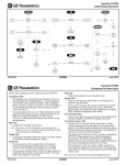
Information Paragraphs
•
Note paragraphs provide information that provides a deeper understanding of the situation, but is not essential to
the proper completion of the instructions.
•
Important paragraphs provide information that emphasizes instructions that are essential to proper setup of the
equipment. Failure to follow these instructions carefully may cause unreliable performance.
•
Caution! paragraphs provide information that alerts the operator to a hazardous situation that can cause damage to
property or equipment.
•
Warning! paragraphs provide information that alerts the operator to a hazardous situation that can cause injury to
personnel. Cautionary information is also included, when applicable.
Safety Issues
WARNING! It is the responsibility of the user to make sure all local, county, state and national codes,
regulations, rules and laws related to safety and safe operating conditions are met for each
installation.
Auxiliary Equipment
Local Safety Standards
The user must make sure that he operates all auxiliary equipment in accordance with local codes, standards,
regulations, or laws applicable to safety.
Working Area
WARNING! Auxiliary equipment may have both manual and automatic modes of operation. As equipment
can move suddenly and without warning, do not enter the work cell of this equipment during
automatic operation, and do not enter the work envelope of this equipment during manual
operation. If you do, serious injury can result.
WARNING! Make sure that power to the auxiliary equipment is turned OFF and locked out before you
perform maintenance procedures on the equipment.
Qualification of Personnel
Make sure that all personnel have manufacturer-approved training applicable to the auxiliary equipment.
Personal Safety Equipment
Make sure that operators and maintenance personnel have all safety equipment applicable to the auxiliary equipment.
Examples include safety glasses, protective headgear, safety shoes, etc.
Unauthorized Operation
Make sure that unauthorized personnel cannot gain access to the operation of the equipment.
Sentinel LCT User’s Manual
iii
Preface
Environmental Compliance
Waste Electrical and Electronic Equipment (WEEE) Directive
GE Measurement & Control Solutions is an active participant in Europe’s Waste Electrical and Electronic Equipment
(WEEE) take-back initiative, directive 2002/96/EC.
The equipment that you bought has required the extraction and use of natural resources for its production. It may
contain hazardous substances that could impact health and the environment.
In order to avoid the dissemination of those substances in our environment and to diminish the pressure on the natural
resources, we encourage you to use the appropriate take-back systems. Those systems will reuse or recycle most of the
materials of your end life equipment in a sound way.
The crossed-out wheeled bin symbol invites you to use those systems.
If you need more information on the collection, reuse and recycling systems, please contact your local or regional
waste administration.
Visit http://www.ge-mcs.com/en/about-us/environmental-health-and-safety/1741-weee-req.html for
take-back instructions and more information about this initiative.
iv
Sentinel LCT User’s Manual
Contents
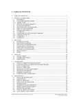
Chapter 1. Features and Capabilities
1.1
1.2
1.3
1.4
1.5
Overview. . . . . . . . . . . . . . . . . . . . . . . . . . . . . . . . . . . . . . . . . . . . . . . . . . . . . . . . . . . . . . . . . . . . . . . . . . . . . . . . . . . . . . . . . . . . . . . 1
1.1.1 Applications . . . . . . . . . . . . . . . . . . . . . . . . . . . . . . . . . . . . . . . . . . . . . . . . . . . . . . . . . . . . . . . . . . . . . . . . . . . . . . . . . . . . 1
1.1.2 Advantages . . . . . . . . . . . . . . . . . . . . . . . . . . . . . . . . . . . . . . . . . . . . . . . . . . . . . . . . . . . . . . . . . . . . . . . . . . . . . . . . . . . . 1
1.1.3 Meter Components . . . . . . . . . . . . . . . . . . . . . . . . . . . . . . . . . . . . . . . . . . . . . . . . . . . . . . . . . . . . . . . . . . . . . . . . . . . . . 2
1.1.4 Name and Specification Plate . . . . . . . . . . . . . . . . . . . . . . . . . . . . . . . . . . . . . . . . . . . . . . . . . . . . . . . . . . . . . . . . . . . 5
Theory of Operation . . . . . . . . . . . . . . . . . . . . . . . . . . . . . . . . . . . . . . . . . . . . . . . . . . . . . . . . . . . . . . . . . . . . . . . . . . . . . . . . . . . . 5
1.2.1 Transit-Time Method. . . . . . . . . . . . . . . . . . . . . . . . . . . . . . . . . . . . . . . . . . . . . . . . . . . . . . . . . . . . . . . . . . . . . . . . . . . . 6
1.2.2 Transducers . . . . . . . . . . . . . . . . . . . . . . . . . . . . . . . . . . . . . . . . . . . . . . . . . . . . . . . . . . . . . . . . . . . . . . . . . . . . . . . . . . . . 6
1.2.3 Multipath Design. . . . . . . . . . . . . . . . . . . . . . . . . . . . . . . . . . . . . . . . . . . . . . . . . . . . . . . . . . . . . . . . . . . . . . . . . . . . . . . . 7
1.2.4 Flow Profile . . . . . . . . . . . . . . . . . . . . . . . . . . . . . . . . . . . . . . . . . . . . . . . . . . . . . . . . . . . . . . . . . . . . . . . . . . . . . . . . . . . . . 7
1.2.5 Maximum and Minimum Flow . . . . . . . . . . . . . . . . . . . . . . . . . . . . . . . . . . . . . . . . . . . . . . . . . . . . . . . . . . . . . . . . . . . 8
Specifications . . . . . . . . . . . . . . . . . . . . . . . . . . . . . . . . . . . . . . . . . . . . . . . . . . . . . . . . . . . . . . . . . . . . . . . . . . . . . . . . . . . . . . . . .10
1.3.1 Operation and Performance. . . . . . . . . . . . . . . . . . . . . . . . . . . . . . . . . . . . . . . . . . . . . . . . . . . . . . . . . . . . . . . . . . . .10
1.3.2 Meter Body . . . . . . . . . . . . . . . . . . . . . . . . . . . . . . . . . . . . . . . . . . . . . . . . . . . . . . . . . . . . . . . . . . . . . . . . . . . . . . . . . . . .11
1.3.3 Electronics. . . . . . . . . . . . . . . . . . . . . . . . . . . . . . . . . . . . . . . . . . . . . . . . . . . . . . . . . . . . . . . . . . . . . . . . . . . . . . . . . . . . .14
1.3.4 Custody Transfer Approvals . . . . . . . . . . . . . . . . . . . . . . . . . . . . . . . . . . . . . . . . . . . . . . . . . . . . . . . . . . . . . . . . . . . .15
1.3.5 Ordering Information . . . . . . . . . . . . . . . . . . . . . . . . . . . . . . . . . . . . . . . . . . . . . . . . . . . . . . . . . . . . . . . . . . . . . . . . . .16
Disclaimer . . . . . . . . . . . . . . . . . . . . . . . . . . . . . . . . . . . . . . . . . . . . . . . . . . . . . . . . . . . . . . . . . . . . . . . . . . . . . . . . . . . . . . . . . . . .18
Warnings and Cautions . . . . . . . . . . . . . . . . . . . . . . . . . . . . . . . . . . . . . . . . . . . . . . . . . . . . . . . . . . . . . . . . . . . . . . . . . . . . . . . .18
Chapter 2. Installation
2.1
2.2
2.3
2.4
Installation Guidelines . . . . . . . . . . . . . . . . . . . . . . . . . . . . . . . . . . . . . . . . . . . . . . . . . . . . . . . . . . . . . . . . . . . . . . . . . . . . . . . . .19
Bill of Materials . . . . . . . . . . . . . . . . . . . . . . . . . . . . . . . . . . . . . . . . . . . . . . . . . . . . . . . . . . . . . . . . . . . . . . . . . . . . . . . . . . . . . . . .19
Mechanical Installation . . . . . . . . . . . . . . . . . . . . . . . . . . . . . . . . . . . . . . . . . . . . . . . . . . . . . . . . . . . . . . . . . . . . . . . . . . . . . . . .20
2.3.1 Location. . . . . . . . . . . . . . . . . . . . . . . . . . . . . . . . . . . . . . . . . . . . . . . . . . . . . . . . . . . . . . . . . . . . . . . . . . . . . . . . . . . . . . .20
2.3.2 Installation Precautions . . . . . . . . . . . . . . . . . . . . . . . . . . . . . . . . . . . . . . . . . . . . . . . . . . . . . . . . . . . . . . . . . . . . . . . .21
2.3.3 Installing the System. . . . . . . . . . . . . . . . . . . . . . . . . . . . . . . . . . . . . . . . . . . . . . . . . . . . . . . . . . . . . . . . . . . . . . . . . . .22
2.3.4 Guidelines for Installing Pipe Insulation . . . . . . . . . . . . . . . . . . . . . . . . . . . . . . . . . . . . . . . . . . . . . . . . . . . . . . . . .22
Making Electrical Connections . . . . . . . . . . . . . . . . . . . . . . . . . . . . . . . . . . . . . . . . . . . . . . . . . . . . . . . . . . . . . . . . . . . . . . . . .23
2.4.1 Removing the Covers . . . . . . . . . . . . . . . . . . . . . . . . . . . . . . . . . . . . . . . . . . . . . . . . . . . . . . . . . . . . . . . . . . . . . . . . . .24
2.4.2 Cable Tie-Down Posts . . . . . . . . . . . . . . . . . . . . . . . . . . . . . . . . . . . . . . . . . . . . . . . . . . . . . . . . . . . . . . . . . . . . . . . . . .25
2.4.3 Wiring the Line Power . . . . . . . . . . . . . . . . . . . . . . . . . . . . . . . . . . . . . . . . . . . . . . . . . . . . . . . . . . . . . . . . . . . . . . . . . .26
2.4.4 Wiring the Serial Port . . . . . . . . . . . . . . . . . . . . . . . . . . . . . . . . . . . . . . . . . . . . . . . . . . . . . . . . . . . . . . . . . . . . . . . . . .28
2.4.5 Wiring the Modbus Communications Line (Optional) . . . . . . . . . . . . . . . . . . . . . . . . . . . . . . . . . . . . . . . . . . . . .28
2.4.6 Wiring the Alarm Relay . . . . . . . . . . . . . . . . . . . . . . . . . . . . . . . . . . . . . . . . . . . . . . . . . . . . . . . . . . . . . . . . . . . . . . . . .29
2.4.7 Wiring the 4-20mA Analog Input (Optional) . . . . . . . . . . . . . . . . . . . . . . . . . . . . . . . . . . . . . . . . . . . . . . . . . . . . . .30
2.4.8 Wiring the Frequency/Totalizer Output. . . . . . . . . . . . . . . . . . . . . . . . . . . . . . . . . . . . . . . . . . . . . . . . . . . . . . . . . .34
2.4.9 Wiring the 4-20 mA Analog Output . . . . . . . . . . . . . . . . . . . . . . . . . . . . . . . . . . . . . . . . . . . . . . . . . . . . . . . . . . . . .35
Sentinel LCT User’s Manual
v
Contents
Chapter 3. General Programming
3.1
3.2
3.3
3.4
3.5
3.6
3.7
3.8
3.9
3.10
3.11
3.12
3.13
vi
Introduction. . . . . . . . . . . . . . . . . . . . . . . . . . . . . . . . . . . . . . . . . . . . . . . . . . . . . . . . . . . . . . . . . . . . . . . . . . . . . . . . . . . . . . . . . . .41
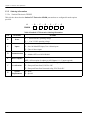
Keypad Features . . . . . . . . . . . . . . . . . . . . . . . . . . . . . . . . . . . . . . . . . . . . . . . . . . . . . . . . . . . . . . . . . . . . . . . . . . . . . . . . . . . . . .41
3.2.1 Indicator Lights. . . . . . . . . . . . . . . . . . . . . . . . . . . . . . . . . . . . . . . . . . . . . . . . . . . . . . . . . . . . . . . . . . . . . . . . . . . . . . . .42
3.2.2 The Magnetic Stylus . . . . . . . . . . . . . . . . . . . . . . . . . . . . . . . . . . . . . . . . . . . . . . . . . . . . . . . . . . . . . . . . . . . . . . . . . . .42
Program Menu Options . . . . . . . . . . . . . . . . . . . . . . . . . . . . . . . . . . . . . . . . . . . . . . . . . . . . . . . . . . . . . . . . . . . . . . . . . . . . . . . .43
3.3.1 Channel Program . . . . . . . . . . . . . . . . . . . . . . . . . . . . . . . . . . . . . . . . . . . . . . . . . . . . . . . . . . . . . . . . . . . . . . . . . . . . . .43
3.3.2 Composite Program . . . . . . . . . . . . . . . . . . . . . . . . . . . . . . . . . . . . . . . . . . . . . . . . . . . . . . . . . . . . . . . . . . . . . . . . . . .43
3.3.3 Advanced Program . . . . . . . . . . . . . . . . . . . . . . . . . . . . . . . . . . . . . . . . . . . . . . . . . . . . . . . . . . . . . . . . . . . . . . . . . . . .43
Unlocking and Locking . . . . . . . . . . . . . . . . . . . . . . . . . . . . . . . . . . . . . . . . . . . . . . . . . . . . . . . . . . . . . . . . . . . . . . . . . . . . . . . .44
3.4.1 Unlocking the Sentinel LCT . . . . . . . . . . . . . . . . . . . . . . . . . . . . . . . . . . . . . . . . . . . . . . . . . . . . . . . . . . . . . . . . . . . . .44
3.4.2 Locking the Sentinel LCT . . . . . . . . . . . . . . . . . . . . . . . . . . . . . . . . . . . . . . . . . . . . . . . . . . . . . . . . . . . . . . . . . . . . . . .45
Setting Security . . . . . . . . . . . . . . . . . . . . . . . . . . . . . . . . . . . . . . . . . . . . . . . . . . . . . . . . . . . . . . . . . . . . . . . . . . . . . . . . . . . . . . .46
3.5.1 Edit Passcodes . . . . . . . . . . . . . . . . . . . . . . . . . . . . . . . . . . . . . . . . . . . . . . . . . . . . . . . . . . . . . . . . . . . . . . . . . . . . . . . .46
3.5.2 Security Timeout . . . . . . . . . . . . . . . . . . . . . . . . . . . . . . . . . . . . . . . . . . . . . . . . . . . . . . . . . . . . . . . . . . . . . . . . . . . . . .46
3.5.3 Set Security . . . . . . . . . . . . . . . . . . . . . . . . . . . . . . . . . . . . . . . . . . . . . . . . . . . . . . . . . . . . . . . . . . . . . . . . . . . . . . . . . . .46
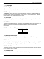
Channel Programming . . . . . . . . . . . . . . . . . . . . . . . . . . . . . . . . . . . . . . . . . . . . . . . . . . . . . . . . . . . . . . . . . . . . . . . . . . . . . . . .47
3.6.1 Activating a Channel/Path/CHX (Status). . . . . . . . . . . . . . . . . . . . . . . . . . . . . . . . . . . . . . . . . . . . . . . . . . . . . . . . .47
3.6.2 Entering Fluid Data (Not supported at this time) . . . . . . . . . . . . . . . . . . . . . . . . . . . . . . . . . . . . . . . . . . . . . . . . .48
3.6.3 Entering Signal Parameters . . . . . . . . . . . . . . . . . . . . . . . . . . . . . . . . . . . . . . . . . . . . . . . . . . . . . . . . . . . . . . . . . . . .49
3.6.4 Entering Error Limits . . . . . . . . . . . . . . . . . . . . . . . . . . . . . . . . . . . . . . . . . . . . . . . . . . . . . . . . . . . . . . . . . . . . . . . . . . .50
Composite Programming . . . . . . . . . . . . . . . . . . . . . . . . . . . . . . . . . . . . . . . . . . . . . . . . . . . . . . . . . . . . . . . . . . . . . . . . . . . . . .51
3.7.1 Entering Fluid Type . . . . . . . . . . . . . . . . . . . . . . . . . . . . . . . . . . . . . . . . . . . . . . . . . . . . . . . . . . . . . . . . . . . . . . . . . . . .51
3.7.2 Entering Signal Parameters . . . . . . . . . . . . . . . . . . . . . . . . . . . . . . . . . . . . . . . . . . . . . . . . . . . . . . . . . . . . . . . . . . . .52
3.7.3 Setting Up Input Data Feeds . . . . . . . . . . . . . . . . . . . . . . . . . . . . . . . . . . . . . . . . . . . . . . . . . . . . . . . . . . . . . . . . . . .52
3.7.4 Setting Up API . . . . . . . . . . . . . . . . . . . . . . . . . . . . . . . . . . . . . . . . . . . . . . . . . . . . . . . . . . . . . . . . . . . . . . . . . . . . . . . . .53
Configuration . . . . . . . . . . . . . . . . . . . . . . . . . . . . . . . . . . . . . . . . . . . . . . . . . . . . . . . . . . . . . . . . . . . . . . . . . . . . . . . . . . . . . . . . .54
Inputs/Outputs. . . . . . . . . . . . . . . . . . . . . . . . . . . . . . . . . . . . . . . . . . . . . . . . . . . . . . . . . . . . . . . . . . . . . . . . . . . . . . . . . . . . . . .55
3.9.1 Analog Outputs. . . . . . . . . . . . . . . . . . . . . . . . . . . . . . . . . . . . . . . . . . . . . . . . . . . . . . . . . . . . . . . . . . . . . . . . . . . . . . . .55
3.9.2 Frequency/Totalizers. . . . . . . . . . . . . . . . . . . . . . . . . . . . . . . . . . . . . . . . . . . . . . . . . . . . . . . . . . . . . . . . . . . . . . . . . . .56
3.9.3 Alarms . . . . . . . . . . . . . . . . . . . . . . . . . . . . . . . . . . . . . . . . . . . . . . . . . . . . . . . . . . . . . . . . . . . . . . . . . . . . . . . . . . . . . . . .57
3.9.4 Analog Inputs (Additional Option) . . . . . . . . . . . . . . . . . . . . . . . . . . . . . . . . . . . . . . . . . . . . . . . . . . . . . . . . . . . . . . .58
3.9.5 RTD (Additional Option). . . . . . . . . . . . . . . . . . . . . . . . . . . . . . . . . . . . . . . . . . . . . . . . . . . . . . . . . . . . . . . . . . . . . . . . .59
Display . . . . . . . . . . . . . . . . . . . . . . . . . . . . . . . . . . . . . . . . . . . . . . . . . . . . . . . . . . . . . . . . . . . . . . . . . . . . . . . . . . . . . . . . . . . . . .59
Calibration . . . . . . . . . . . . . . . . . . . . . . . . . . . . . . . . . . . . . . . . . . . . . . . . . . . . . . . . . . . . . . . . . . . . . . . . . . . . . . . . . . . . . . . . . . .60
User Security. . . . . . . . . . . . . . . . . . . . . . . . . . . . . . . . . . . . . . . . . . . . . . . . . . . . . . . . . . . . . . . . . . . . . . . . . . . . . . . . . . . . . . . . .60
3.12.1 Edit Passcodes . . . . . . . . . . . . . . . . . . . . . . . . . . . . . . . . . . . . . . . . . . . . . . . . . . . . . . . . . . . . . . . . . . . . . . . . . . . . . . . .60
3.12.2 Security Timeout . . . . . . . . . . . . . . . . . . . . . . . . . . . . . . . . . . . . . . . . . . . . . . . . . . . . . . . . . . . . . . . . . . . . . . . . . . . . . .60
3.12.3 Set Security . . . . . . . . . . . . . . . . . . . . . . . . . . . . . . . . . . . . . . . . . . . . . . . . . . . . . . . . . . . . . . . . . . . . . . . . . . . . . . . . . . .60
Factory Status . . . . . . . . . . . . . . . . . . . . . . . . . . . . . . . . . . . . . . . . . . . . . . . . . . . . . . . . . . . . . . . . . . . . . . . . . . . . . . . . . . . . . . .61
Sentinel LCT User’s Manual
Contents
Chapter 4. Advanced Programming
4.1
4.2
4.3
4.4
4.5
4.6
4.7
Entering Transducer Parameters . . . . . . . . . . . . . . . . . . . . . . . . . . . . . . . . . . . . . . . . . . . . . . . . . . . . . . . . . . . . . . . . . . . . . . .63
4.1.1 Clamp-On Transducers. . . . . . . . . . . . . . . . . . . . . . . . . . . . . . . . . . . . . . . . . . . . . . . . . . . . . . . . . . . . . . . . . . . . . . . . .63
4.1.2 Other Transducers . . . . . . . . . . . . . . . . . . . . . . . . . . . . . . . . . . . . . . . . . . . . . . . . . . . . . . . . . . . . . . . . . . . . . . . . . . . . .64
4.1.3 Wetted Transducers . . . . . . . . . . . . . . . . . . . . . . . . . . . . . . . . . . . . . . . . . . . . . . . . . . . . . . . . . . . . . . . . . . . . . . . . . . .64
Entering Path Data . . . . . . . . . . . . . . . . . . . . . . . . . . . . . . . . . . . . . . . . . . . . . . . . . . . . . . . . . . . . . . . . . . . . . . . . . . . . . . . . . . . .65
Entering Signal Parameters . . . . . . . . . . . . . . . . . . . . . . . . . . . . . . . . . . . . . . . . . . . . . . . . . . . . . . . . . . . . . . . . . . . . . . . . . . . .65
Entering the Meter Correction (K) Factor . . . . . . . . . . . . . . . . . . . . . . . . . . . . . . . . . . . . . . . . . . . . . . . . . . . . . . . . . . . . . . . .67
Entering Pipe Parameters . . . . . . . . . . . . . . . . . . . . . . . . . . . . . . . . . . . . . . . . . . . . . . . . . . . . . . . . . . . . . . . . . . . . . . . . . . . . . .68
Entering the Pipe Material. . . . . . . . . . . . . . . . . . . . . . . . . . . . . . . . . . . . . . . . . . . . . . . . . . . . . . . . . . . . . . . . . . . . . . . . . . . . . .69
Entering Pipe Lining Data . . . . . . . . . . . . . . . . . . . . . . . . . . . . . . . . . . . . . . . . . . . . . . . . . . . . . . . . . . . . . . . . . . . . . . . . . . . . . .70
Chapter 5. Using PanaView
5.1
5.2
5.3
5.4
5.5
5.6
5.7
Introduction . . . . . . . . . . . . . . . . . . . . . . . . . . . . . . . . . . . . . . . . . . . . . . . . . . . . . . . . . . . . . . . . . . . . . . . . . . . . . . . . . . . . . . . . . . .71
Wiring the RS232 Interface. . . . . . . . . . . . . . . . . . . . . . . . . . . . . . . . . . . . . . . . . . . . . . . . . . . . . . . . . . . . . . . . . . . . . . . . . . . . .71
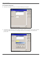
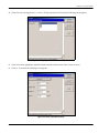
Establishing Communications with Panaview™ . . . . . . . . . . . . . . . . . . . . . . . . . . . . . . . . . . . . . . . . . . . . . . . . . . . . . . . . .71
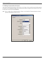
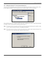
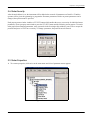
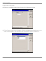
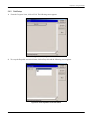
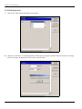
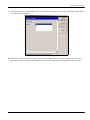
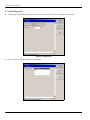
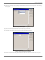
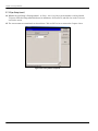
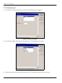
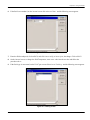
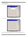
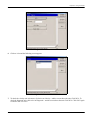
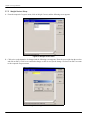
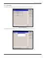
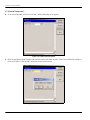
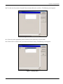
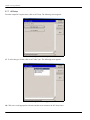
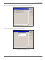
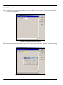
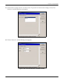
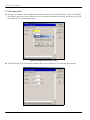
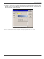
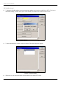
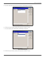
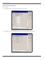
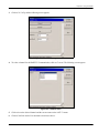
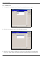
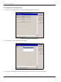
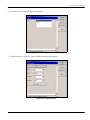
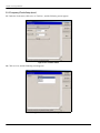
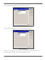
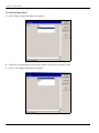
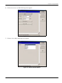
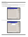
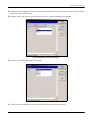
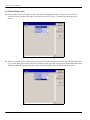
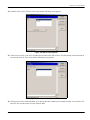
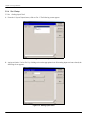
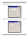
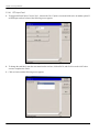
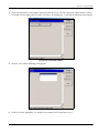
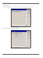
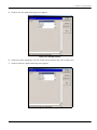
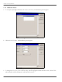
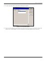
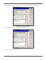
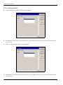
5.3.1 Adding a Communications Port. . . . . . . . . . . . . . . . . . . . . . . . . . . . . . . . . . . . . . . . . . . . . . . . . . . . . . . . . . . . . . . . .71
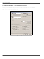
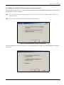
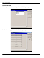
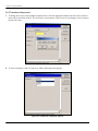
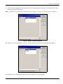
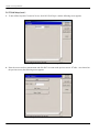
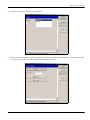
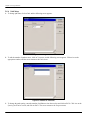
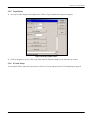
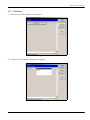
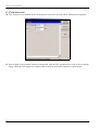
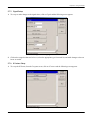
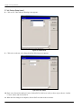
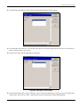
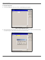
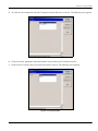
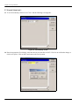
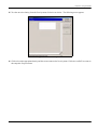
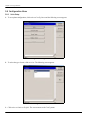
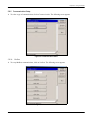
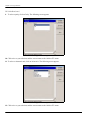
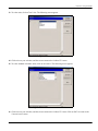
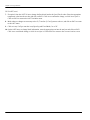
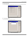
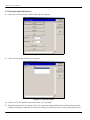
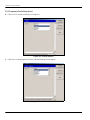
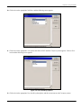
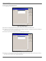
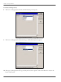
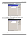
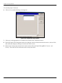
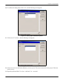
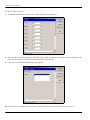
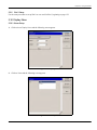
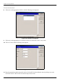
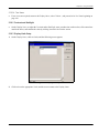
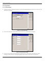
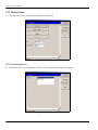
5.3.2 Adding the Sentinel LCT to the Communications Port . . . . . . . . . . . . . . . . . . . . . . . . . . . . . . . . . . . . . . . . . . . .73
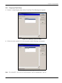
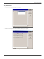
Meter Security. . . . . . . . . . . . . . . . . . . . . . . . . . . . . . . . . . . . . . . . . . . . . . . . . . . . . . . . . . . . . . . . . . . . . . . . . . . . . . . . . . . . . . . . .77
Meter Properties. . . . . . . . . . . . . . . . . . . . . . . . . . . . . . . . . . . . . . . . . . . . . . . . . . . . . . . . . . . . . . . . . . . . . . . . . . . . . . . . . . . . . . .77
Program Menu . . . . . . . . . . . . . . . . . . . . . . . . . . . . . . . . . . . . . . . . . . . . . . . . . . . . . . . . . . . . . . . . . . . . . . . . . . . . . . . . . . . . . . . .78
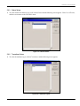
5.6.1 Status Setup . . . . . . . . . . . . . . . . . . . . . . . . . . . . . . . . . . . . . . . . . . . . . . . . . . . . . . . . . . . . . . . . . . . . . . . . . . . . . . . . . . .79
5.6.2 Transducer Setup . . . . . . . . . . . . . . . . . . . . . . . . . . . . . . . . . . . . . . . . . . . . . . . . . . . . . . . . . . . . . . . . . . . . . . . . . . . . . .79
5.6.3 Fluid Setup . . . . . . . . . . . . . . . . . . . . . . . . . . . . . . . . . . . . . . . . . . . . . . . . . . . . . . . . . . . . . . . . . . . . . . . . . . . . . . . . . . . .85
5.6.4 Path Setup . . . . . . . . . . . . . . . . . . . . . . . . . . . . . . . . . . . . . . . . . . . . . . . . . . . . . . . . . . . . . . . . . . . . . . . . . . . . . . . . . . . .90
5.6.5 Signal Setup . . . . . . . . . . . . . . . . . . . . . . . . . . . . . . . . . . . . . . . . . . . . . . . . . . . . . . . . . . . . . . . . . . . . . . . . . . . . . . . . . . .91
5.6.6 K Factor Setup . . . . . . . . . . . . . . . . . . . . . . . . . . . . . . . . . . . . . . . . . . . . . . . . . . . . . . . . . . . . . . . . . . . . . . . . . . . . . . . . .91
5.6.7 Error Limits Setup . . . . . . . . . . . . . . . . . . . . . . . . . . . . . . . . . . . . . . . . . . . . . . . . . . . . . . . . . . . . . . . . . . . . . . . . . . . . . .92
Composite Programs . . . . . . . . . . . . . . . . . . . . . . . . . . . . . . . . . . . . . . . . . . . . . . . . . . . . . . . . . . . . . . . . . . . . . . . . . . . . . . . . . .93
5.7.1 Pipe Setup . . . . . . . . . . . . . . . . . . . . . . . . . . . . . . . . . . . . . . . . . . . . . . . . . . . . . . . . . . . . . . . . . . . . . . . . . . . . . . . . . . . . .93
5.7.2 Fluid Setup . . . . . . . . . . . . . . . . . . . . . . . . . . . . . . . . . . . . . . . . . . . . . . . . . . . . . . . . . . . . . . . . . . . . . . . . . . . . . . . . . . . .99
5.7.3 Signal Setup . . . . . . . . . . . . . . . . . . . . . . . . . . . . . . . . . . . . . . . . . . . . . . . . . . . . . . . . . . . . . . . . . . . . . . . . . . . . . . . . . 103
5.7.4 K Factors Setup. . . . . . . . . . . . . . . . . . . . . . . . . . . . . . . . . . . . . . . . . . . . . . . . . . . . . . . . . . . . . . . . . . . . . . . . . . . . . . 103
5.7.5 Weight Factors Setup . . . . . . . . . . . . . . . . . . . . . . . . . . . . . . . . . . . . . . . . . . . . . . . . . . . . . . . . . . . . . . . . . . . . . . . . 108
5.7.6 Inputs Setup . . . . . . . . . . . . . . . . . . . . . . . . . . . . . . . . . . . . . . . . . . . . . . . . . . . . . . . . . . . . . . . . . . . . . . . . . . . . . . . . . 109
5.7.7 API Setup . . . . . . . . . . . . . . . . . . . . . . . . . . . . . . . . . . . . . . . . . . . . . . . . . . . . . . . . . . . . . . . . . . . . . . . . . . . . . . . . . . . . 116
Sentinel LCT User’s Manual
vii
Contents
Chapter 5. Using PanaView (cont.)
5.8
5.9
5.10
5.11
5.12
5.13
Configuration Menu . . . . . . . . . . . . . . . . . . . . . . . . . . . . . . . . . . . . . . . . . . . . . . . . . . . . . . . . . . . . . . . . . . . . . . . . . . . . . . . . .
5.8.1 Units Setup . . . . . . . . . . . . . . . . . . . . . . . . . . . . . . . . . . . . . . . . . . . . . . . . . . . . . . . . . . . . . . . . . . . . . . . . . . . . . . . . . .
5.8.2 Communication Setup . . . . . . . . . . . . . . . . . . . . . . . . . . . . . . . . . . . . . . . . . . . . . . . . . . . . . . . . . . . . . . . . . . . . . . .
5.8.3 Reset Totals . . . . . . . . . . . . . . . . . . . . . . . . . . . . . . . . . . . . . . . . . . . . . . . . . . . . . . . . . . . . . . . . . . . . . . . . . . . . . . . . .
5.8.4 Totalizer Errors . . . . . . . . . . . . . . . . . . . . . . . . . . . . . . . . . . . . . . . . . . . . . . . . . . . . . . . . . . . . . . . . . . . . . . . . . . . . . .
Input/Output Menu . . . . . . . . . . . . . . . . . . . . . . . . . . . . . . . . . . . . . . . . . . . . . . . . . . . . . . . . . . . . . . . . . . . . . . . . . . . . . . . . . .
5.9.1 Analog Outputs Setup. . . . . . . . . . . . . . . . . . . . . . . . . . . . . . . . . . . . . . . . . . . . . . . . . . . . . . . . . . . . . . . . . . . . . . . .
5.9.2 Frequency/Totals Setup . . . . . . . . . . . . . . . . . . . . . . . . . . . . . . . . . . . . . . . . . . . . . . . . . . . . . . . . . . . . . . . . . . . . . .
5.9.3 Alarms Setup . . . . . . . . . . . . . . . . . . . . . . . . . . . . . . . . . . . . . . . . . . . . . . . . . . . . . . . . . . . . . . . . . . . . . . . . . . . . . . . .
5.9.4 Slot 1 Setup . . . . . . . . . . . . . . . . . . . . . . . . . . . . . . . . . . . . . . . . . . . . . . . . . . . . . . . . . . . . . . . . . . . . . . . . . . . . . . . . .
5.9.5 Slot 2 Setup . . . . . . . . . . . . . . . . . . . . . . . . . . . . . . . . . . . . . . . . . . . . . . . . . . . . . . . . . . . . . . . . . . . . . . . . . . . . . . . . .
Display Menu . . . . . . . . . . . . . . . . . . . . . . . . . . . . . . . . . . . . . . . . . . . . . . . . . . . . . . . . . . . . . . . . . . . . . . . . . . . . . . . . . . . . . .
5.10.1 Views Setup . . . . . . . . . . . . . . . . . . . . . . . . . . . . . . . . . . . . . . . . . . . . . . . . . . . . . . . . . . . . . . . . . . . . . . . . . . . . . . . . .
5.10.2 Contrast and Backlight. . . . . . . . . . . . . . . . . . . . . . . . . . . . . . . . . . . . . . . . . . . . . . . . . . . . . . . . . . . . . . . . . . . . . . .
5.10.3 Display Mode Setup. . . . . . . . . . . . . . . . . . . . . . . . . . . . . . . . . . . . . . . . . . . . . . . . . . . . . . . . . . . . . . . . . . . . . . . . . .
Calibrate Menu. . . . . . . . . . . . . . . . . . . . . . . . . . . . . . . . . . . . . . . . . . . . . . . . . . . . . . . . . . . . . . . . . . . . . . . . . . . . . . . . . . . . .
User Menu . . . . . . . . . . . . . . . . . . . . . . . . . . . . . . . . . . . . . . . . . . . . . . . . . . . . . . . . . . . . . . . . . . . . . . . . . . . . . . . . . . . . . . . . .
5.12.1 Edit Passcodes . . . . . . . . . . . . . . . . . . . . . . . . . . . . . . . . . . . . . . . . . . . . . . . . . . . . . . . . . . . . . . . . . . . . . . . . . . . . . .
5.12.2 Set Security . . . . . . . . . . . . . . . . . . . . . . . . . . . . . . . . . . . . . . . . . . . . . . . . . . . . . . . . . . . . . . . . . . . . . . . . . . . . . . . . .
Factory Menu . . . . . . . . . . . . . . . . . . . . . . . . . . . . . . . . . . . . . . . . . . . . . . . . . . . . . . . . . . . . . . . . . . . . . . . . . . . . . . . . . . . . . .
5.13.1 Checking Versions . . . . . . . . . . . . . . . . . . . . . . . . . . . . . . . . . . . . . . . . . . . . . . . . . . . . . . . . . . . . . . . . . . . . . . . . . . .
5.13.2 Confirming Meters. . . . . . . . . . . . . . . . . . . . . . . . . . . . . . . . . . . . . . . . . . . . . . . . . . . . . . . . . . . . . . . . . . . . . . . . . . .
122
122
123
131
132
133
133
135
143
152
159
159
159
163
163
164
166
166
167
168
168
170
Chapter 6. MODBUS Communications
6.1
6.2
viii
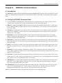
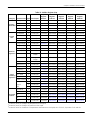
Introduction. . . . . . . . . . . . . . . . . . . . . . . . . . . . . . . . . . . . . . . . . . . . . . . . . . . . . . . . . . . . . . . . . . . . . . . . . . . . . . . . . . . . . . . . . 173
Setting Up MODBUS Communications . . . . . . . . . . . . . . . . . . . . . . . . . . . . . . . . . . . . . . . . . . . . . . . . . . . . . . . . . . . . . . . . 173
Sentinel LCT User’s Manual
Contents
Chapter 7. HART Communications
7.1
7.2
7.3
7.4
7.5
7.6
7.7
7.8
7.9
7.10
7.11
7.12
7.13
7.14
7.15
Introduction . . . . . . . . . . . . . . . . . . . . . . . . . . . . . . . . . . . . . . . . . . . . . . . . . . . . . . . . . . . . . . . . . . . . . . . . . . . . . . . . . . . . . . . . .
Wiring the HART Interface . . . . . . . . . . . . . . . . . . . . . . . . . . . . . . . . . . . . . . . . . . . . . . . . . . . . . . . . . . . . . . . . . . . . . . . . . . .
Flowmeter Software Setup . . . . . . . . . . . . . . . . . . . . . . . . . . . . . . . . . . . . . . . . . . . . . . . . . . . . . . . . . . . . . . . . . . . . . . . . . . .
Product Interfaces. . . . . . . . . . . . . . . . . . . . . . . . . . . . . . . . . . . . . . . . . . . . . . . . . . . . . . . . . . . . . . . . . . . . . . . . . . . . . . . . . . .
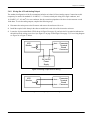
7.4.1 Process Interface . . . . . . . . . . . . . . . . . . . . . . . . . . . . . . . . . . . . . . . . . . . . . . . . . . . . . . . . . . . . . . . . . . . . . . . . . . . .
7.4.2 Host Interface . . . . . . . . . . . . . . . . . . . . . . . . . . . . . . . . . . . . . . . . . . . . . . . . . . . . . . . . . . . . . . . . . . . . . . . . . . . . . . .
Device Variables. . . . . . . . . . . . . . . . . . . . . . . . . . . . . . . . . . . . . . . . . . . . . . . . . . . . . . . . . . . . . . . . . . . . . . . . . . . . . . . . . . . . .
Dynamic Variables . . . . . . . . . . . . . . . . . . . . . . . . . . . . . . . . . . . . . . . . . . . . . . . . . . . . . . . . . . . . . . . . . . . . . . . . . . . . . . . . . .
Status Information . . . . . . . . . . . . . . . . . . . . . . . . . . . . . . . . . . . . . . . . . . . . . . . . . . . . . . . . . . . . . . . . . . . . . . . . . . . . . . . . . .
7.7.1 Device Status . . . . . . . . . . . . . . . . . . . . . . . . . . . . . . . . . . . . . . . . . . . . . . . . . . . . . . . . . . . . . . . . . . . . . . . . . . . . . . . .
7.7.2 Extended Device Status . . . . . . . . . . . . . . . . . . . . . . . . . . . . . . . . . . . . . . . . . . . . . . . . . . . . . . . . . . . . . . . . . . . . . .
7.7.3 Additional Device Status . . . . . . . . . . . . . . . . . . . . . . . . . . . . . . . . . . . . . . . . . . . . . . . . . . . . . . . . . . . . . . . . . . . . .
Universal Commands . . . . . . . . . . . . . . . . . . . . . . . . . . . . . . . . . . . . . . . . . . . . . . . . . . . . . . . . . . . . . . . . . . . . . . . . . . . . . . . .
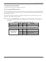
Common-Practice Commands . . . . . . . . . . . . . . . . . . . . . . . . . . . . . . . . . . . . . . . . . . . . . . . . . . . . . . . . . . . . . . . . . . . . . . .
7.9.1 Supported Common Practice Commands . . . . . . . . . . . . . . . . . . . . . . . . . . . . . . . . . . . . . . . . . . . . . . . . . . . . .
7.9.2 Burst Mode Commands . . . . . . . . . . . . . . . . . . . . . . . . . . . . . . . . . . . . . . . . . . . . . . . . . . . . . . . . . . . . . . . . . . . . . .
7.9.3 Catch Device Variable Command . . . . . . . . . . . . . . . . . . . . . . . . . . . . . . . . . . . . . . . . . . . . . . . . . . . . . . . . . . . . .
Device-Specific Commands . . . . . . . . . . . . . . . . . . . . . . . . . . . . . . . . . . . . . . . . . . . . . . . . . . . . . . . . . . . . . . . . . . . . . . . . .
7.10.1 Command 181 (0xB5): Clear Totals . . . . . . . . . . . . . . . . . . . . . . . . . . . . . . . . . . . . . . . . . . . . . . . . . . . . . . . . . . . .
Tables . . . . . . . . . . . . . . . . . . . . . . . . . . . . . . . . . . . . . . . . . . . . . . . . . . . . . . . . . . . . . . . . . . . . . . . . . . . . . . . . . . . . . . . . . . . . .
7.11.1 HART Engineering Units . . . . . . . . . . . . . . . . . . . . . . . . . . . . . . . . . . . . . . . . . . . . . . . . . . . . . . . . . . . . . . . . . . . . . .
Performance . . . . . . . . . . . . . . . . . . . . . . . . . . . . . . . . . . . . . . . . . . . . . . . . . . . . . . . . . . . . . . . . . . . . . . . . . . . . . . . . . . . . . . .
7.12.1 Sampling Rate . . . . . . . . . . . . . . . . . . . . . . . . . . . . . . . . . . . . . . . . . . . . . . . . . . . . . . . . . . . . . . . . . . . . . . . . . . . . . . .
7.12.2 Power-Up . . . . . . . . . . . . . . . . . . . . . . . . . . . . . . . . . . . . . . . . . . . . . . . . . . . . . . . . . . . . . . . . . . . . . . . . . . . . . . . . . . .
7.12.3 Device Reset. . . . . . . . . . . . . . . . . . . . . . . . . . . . . . . . . . . . . . . . . . . . . . . . . . . . . . . . . . . . . . . . . . . . . . . . . . . . . . . . .
7.12.4 Self-Test . . . . . . . . . . . . . . . . . . . . . . . . . . . . . . . . . . . . . . . . . . . . . . . . . . . . . . . . . . . . . . . . . . . . . . . . . . . . . . . . . . . . .
7.12.5 Command Response Delay . . . . . . . . . . . . . . . . . . . . . . . . . . . . . . . . . . . . . . . . . . . . . . . . . . . . . . . . . . . . . . . . . . .
7.12.6 Busy and Delayed Response. . . . . . . . . . . . . . . . . . . . . . . . . . . . . . . . . . . . . . . . . . . . . . . . . . . . . . . . . . . . . . . . . .
7.12.7 Long Messages . . . . . . . . . . . . . . . . . . . . . . . . . . . . . . . . . . . . . . . . . . . . . . . . . . . . . . . . . . . . . . . . . . . . . . . . . . . . . .
7.12.8 Non-Volatile Memory . . . . . . . . . . . . . . . . . . . . . . . . . . . . . . . . . . . . . . . . . . . . . . . . . . . . . . . . . . . . . . . . . . . . . . . .
7.12.9 Operating Modes . . . . . . . . . . . . . . . . . . . . . . . . . . . . . . . . . . . . . . . . . . . . . . . . . . . . . . . . . . . . . . . . . . . . . . . . . . . .
7.12.10 Write Protection. . . . . . . . . . . . . . . . . . . . . . . . . . . . . . . . . . . . . . . . . . . . . . . . . . . . . . . . . . . . . . . . . . . . . . . . . . . . .
7.12.11 Write Protect Switch. . . . . . . . . . . . . . . . . . . . . . . . . . . . . . . . . . . . . . . . . . . . . . . . . . . . . . . . . . . . . . . . . . . . . . . . .
7.12.12 Totals Protect Switch . . . . . . . . . . . . . . . . . . . . . . . . . . . . . . . . . . . . . . . . . . . . . . . . . . . . . . . . . . . . . . . . . . . . . . . .
Capability Checklist. . . . . . . . . . . . . . . . . . . . . . . . . . . . . . . . . . . . . . . . . . . . . . . . . . . . . . . . . . . . . . . . . . . . . . . . . . . . . . . . .
Default Configuration . . . . . . . . . . . . . . . . . . . . . . . . . . . . . . . . . . . . . . . . . . . . . . . . . . . . . . . . . . . . . . . . . . . . . . . . . . . . . .
Revision History . . . . . . . . . . . . . . . . . . . . . . . . . . . . . . . . . . . . . . . . . . . . . . . . . . . . . . . . . . . . . . . . . . . . . . . . . . . . . . . . . . . .
Sentinel LCT User’s Manual
179
179
180
180
180
181
181
185
185
185
185
186
187
187
187
188
188
189
189
190
190
193
193
193
193
193
193
193
193
193
193
194
194
194
194
195
195
ix
Contents
Chapter 8. Maintenance
8.1
8.2
8.3
Calibration . . . . . . . . . . . . . . . . . . . . . . . . . . . . . . . . . . . . . . . . . . . . . . . . . . . . . . . . . . . . . . . . . . . . . . . . . . . . . . . . . . . . . . . . . .
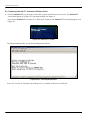
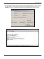
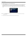
8.1.1 Updating Sentinel LCT Instrument Software . . . . . . . . . . . . . . . . . . . . . . . . . . . . . . . . . . . . . . . . . . . . . . . . . . .
8.1.2 Checking the Meter Software. . . . . . . . . . . . . . . . . . . . . . . . . . . . . . . . . . . . . . . . . . . . . . . . . . . . . . . . . . . . . . . . .
8.1.3 Trimming 4-20 mA Using the Keypad . . . . . . . . . . . . . . . . . . . . . . . . . . . . . . . . . . . . . . . . . . . . . . . . . . . . . . . . .
Spare Parts . . . . . . . . . . . . . . . . . . . . . . . . . . . . . . . . . . . . . . . . . . . . . . . . . . . . . . . . . . . . . . . . . . . . . . . . . . . . . . . . . . . . . . . . .
Installing Replacement Parts. . . . . . . . . . . . . . . . . . . . . . . . . . . . . . . . . . . . . . . . . . . . . . . . . . . . . . . . . . . . . . . . . . . . . . . . .
197
197
201
202
202
202
Chapter 9. Troubleshooting
9.1
9.2
9.3
9.4
9.5
9.6
9.7
x
Introduction. . . . . . . . . . . . . . . . . . . . . . . . . . . . . . . . . . . . . . . . . . . . . . . . . . . . . . . . . . . . . . . . . . . . . . . . . . . . . . . . . . . . . . . . .
Error Codes . . . . . . . . . . . . . . . . . . . . . . . . . . . . . . . . . . . . . . . . . . . . . . . . . . . . . . . . . . . . . . . . . . . . . . . . . . . . . . . . . . . . . . . . .
9.2.1 E0: No Error . . . . . . . . . . . . . . . . . . . . . . . . . . . . . . . . . . . . . . . . . . . . . . . . . . . . . . . . . . . . . . . . . . . . . . . . . . . . . . . . .
9.2.2 E1: Low Signal . . . . . . . . . . . . . . . . . . . . . . . . . . . . . . . . . . . . . . . . . . . . . . . . . . . . . . . . . . . . . . . . . . . . . . . . . . . . . . .
9.2.3 E2: Soundspeed Error . . . . . . . . . . . . . . . . . . . . . . . . . . . . . . . . . . . . . . . . . . . . . . . . . . . . . . . . . . . . . . . . . . . . . . . .
9.2.4 E3: Velocity Range Error . . . . . . . . . . . . . . . . . . . . . . . . . . . . . . . . . . . . . . . . . . . . . . . . . . . . . . . . . . . . . . . . . . . . . .
9.2.5 E4: Signal Quality Error . . . . . . . . . . . . . . . . . . . . . . . . . . . . . . . . . . . . . . . . . . . . . . . . . . . . . . . . . . . . . . . . . . . . . . .
9.2.6 E5: Amplitude Error . . . . . . . . . . . . . . . . . . . . . . . . . . . . . . . . . . . . . . . . . . . . . . . . . . . . . . . . . . . . . . . . . . . . . . . . . .
9.2.7 E6: Cycle Skip, Acceleration Error . . . . . . . . . . . . . . . . . . . . . . . . . . . . . . . . . . . . . . . . . . . . . . . . . . . . . . . . . . . . .
9.2.8 E7: Analog Output Error . . . . . . . . . . . . . . . . . . . . . . . . . . . . . . . . . . . . . . . . . . . . . . . . . . . . . . . . . . . . . . . . . . . . . .
9.2.9 E13: Settle Tracking AGC . . . . . . . . . . . . . . . . . . . . . . . . . . . . . . . . . . . . . . . . . . . . . . . . . . . . . . . . . . . . . . . . . . . . .
9.2.10 E14: Tracking Seek Mode. . . . . . . . . . . . . . . . . . . . . . . . . . . . . . . . . . . . . . . . . . . . . . . . . . . . . . . . . . . . . . . . . . . . .
9.2.11 E15: Active Tw Error. . . . . . . . . . . . . . . . . . . . . . . . . . . . . . . . . . . . . . . . . . . . . . . . . . . . . . . . . . . . . . . . . . . . . . . . . .
9.2.12 E16: Totalizer Overflow Error . . . . . . . . . . . . . . . . . . . . . . . . . . . . . . . . . . . . . . . . . . . . . . . . . . . . . . . . . . . . . . . . .
9.2.13 E17: Temperature Input Error. . . . . . . . . . . . . . . . . . . . . . . . . . . . . . . . . . . . . . . . . . . . . . . . . . . . . . . . . . . . . . . . .
9.2.14 E18: Pressure Input Error . . . . . . . . . . . . . . . . . . . . . . . . . . . . . . . . . . . . . . . . . . . . . . . . . . . . . . . . . . . . . . . . . . . . .
9.2.15 E19: Density Input Error . . . . . . . . . . . . . . . . . . . . . . . . . . . . . . . . . . . . . . . . . . . . . . . . . . . . . . . . . . . . . . . . . . . . . .
9.2.16 E20: Special Input Error . . . . . . . . . . . . . . . . . . . . . . . . . . . . . . . . . . . . . . . . . . . . . . . . . . . . . . . . . . . . . . . . . . . . . .
9.2.17 E21: API Error . . . . . . . . . . . . . . . . . . . . . . . . . . . . . . . . . . . . . . . . . . . . . . . . . . . . . . . . . . . . . . . . . . . . . . . . . . . . . . . .
9.2.18 E22: Degraded Performance Error . . . . . . . . . . . . . . . . . . . . . . . . . . . . . . . . . . . . . . . . . . . . . . . . . . . . . . . . . . . .
9.2.19 E30: Channel Disabled. . . . . . . . . . . . . . . . . . . . . . . . . . . . . . . . . . . . . . . . . . . . . . . . . . . . . . . . . . . . . . . . . . . . . . .
Displaying Diagnostic Parameters . . . . . . . . . . . . . . . . . . . . . . . . . . . . . . . . . . . . . . . . . . . . . . . . . . . . . . . . . . . . . . . . . . .
Fluid and Pipe Problems . . . . . . . . . . . . . . . . . . . . . . . . . . . . . . . . . . . . . . . . . . . . . . . . . . . . . . . . . . . . . . . . . . . . . . . . . . . . .
9.4.1 Fluid Problems. . . . . . . . . . . . . . . . . . . . . . . . . . . . . . . . . . . . . . . . . . . . . . . . . . . . . . . . . . . . . . . . . . . . . . . . . . . . . . .
9.4.2 Pipe Problems . . . . . . . . . . . . . . . . . . . . . . . . . . . . . . . . . . . . . . . . . . . . . . . . . . . . . . . . . . . . . . . . . . . . . . . . . . . . . . .
Transducer Problems . . . . . . . . . . . . . . . . . . . . . . . . . . . . . . . . . . . . . . . . . . . . . . . . . . . . . . . . . . . . . . . . . . . . . . . . . . . . . . . .
9.5.1 Clamp-on Transducer Problems . . . . . . . . . . . . . . . . . . . . . . . . . . . . . . . . . . . . . . . . . . . . . . . . . . . . . . . . . . . . . .
Audit Trail . . . . . . . . . . . . . . . . . . . . . . . . . . . . . . . . . . . . . . . . . . . . . . . . . . . . . . . . . . . . . . . . . . . . . . . . . . . . . . . . . . . . . . . . . . .
9.6.1 Audit Log. . . . . . . . . . . . . . . . . . . . . . . . . . . . . . . . . . . . . . . . . . . . . . . . . . . . . . . . . . . . . . . . . . . . . . . . . . . . . . . . . . . .
9.6.2 Reading Audit Log Records. . . . . . . . . . . . . . . . . . . . . . . . . . . . . . . . . . . . . . . . . . . . . . . . . . . . . . . . . . . . . . . . . . .
9.6.3 Formatting and Viewing Log Records . . . . . . . . . . . . . . . . . . . . . . . . . . . . . . . . . . . . . . . . . . . . . . . . . . . . . . . . .
Uncertainty in Flow Rate for a Non-Insulated Meter. . . . . . . . . . . . . . . . . . . . . . . . . . . . . . . . . . . . . . . . . . . . . . . . . . .
203
203
203
203
204
204
204
204
204
205
205
205
205
205
205
206
206
206
206
206
206
207
209
209
210
210
210
211
211
213
214
215
Sentinel LCT User’s Manual
Contents
Appendix A. Menu Maps
Appendix B. CE Mark Compliance and High Noise Areas
B.1
B.2
Introduction . . . . . . . . . . . . . . . . . . . . . . . . . . . . . . . . . . . . . . . . . . . . . . . . . . . . . . . . . . . . . . . . . . . . . . . . . . . . . . . . . . . . . . . . . 227
EMC Compliance . . . . . . . . . . . . . . . . . . . . . . . . . . . . . . . . . . . . . . . . . . . . . . . . . . . . . . . . . . . . . . . . . . . . . . . . . . . . . . . . . . . . 227
Appendix C. Data Records
C.1 Site Data . . . . . . . . . . . . . . . . . . . . . . . . . . . . . . . . . . . . . . . . . . . . . . . . . . . . . . . . . . . . . . . . . . . . . . . . . . . . . . . . . . . . . . . . . . . . 229
Appendix D. Service Record
D.1 Introduction . . . . . . . . . . . . . . . . . . . . . . . . . . . . . . . . . . . . . . . . . . . . . . . . . . . . . . . . . . . . . . . . . . . . . . . . . . . . . . . . . . . . . . . . . 233
D.2 Data Entry . . . . . . . . . . . . . . . . . . . . . . . . . . . . . . . . . . . . . . . . . . . . . . . . . . . . . . . . . . . . . . . . . . . . . . . . . . . . . . . . . . . . . . . . . . 233
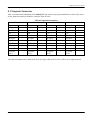
D.3 Diagnostic Parameters . . . . . . . . . . . . . . . . . . . . . . . . . . . . . . . . . . . . . . . . . . . . . . . . . . . . . . . . . . . . . . . . . . . . . . . . . . . . . . 235
Sentinel LCT User’s Manual
xi
Contents
[no content intended for this page]
xii
Sentinel LCT User’s Manual
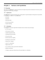
Chapter 1. Features and Capabilities
Chapter 1.
Features and Capabilities
1.1 Overview
The GE Sensing Sentinel LCT is an ultrasonic flowmeter for liquid custody transfer measurement. The entire system is
shipped fully assembled and preconfigured.
1.1.1 Applications
The Sentinel LCT is designed specifically for the custody transfer of petroleum liquids, meeting the strict requirements
of API MPMS 5.8, OIML R117-1 and MID MI-005.
•
Crude Oil
•
Petroleum
•
Refined products
•
Fuel oil to gas turbines
•
Pipeline balancing
1.1.2 Advantages
The Sentinel LCT Ultrasonic Liquid Flow Transmitter features numerous unique advantages:
•
0.15% Accuracy
•
Fast response electronics
•
Advanced signal processing
•
PanAdapta® plug technology
•
Zero pressure drop
•
Bi-directional flow capability
•
Excellent low-end resolution
•
Internal Flow Computer
•
Active Tw compensation
•
High turndown ratio
•
Low sensitivity to many upstream flow disturbances
•
Minimal maintenance
•
Transducer replacement without the need for pipe shutdown or recalibration
Sentinel LCT User’s Manual
1
Chapter 1. Features and Capabilities
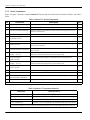
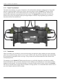
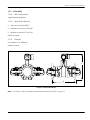
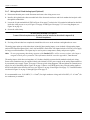
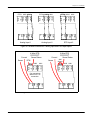
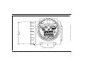
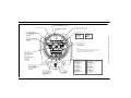
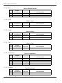
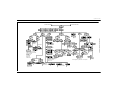
1.1.3 Meter Components
Figure 1 on page 3 shows the complete Sentinel LCT system and each of the items is described in Table 1 and Table 2
below.
Table 1: Sentinel LCT System Components
No.
Component
Description
Qty
1
Meter Body
Measurement section of a Sentinel LCT System.
1
2
Name and Specification Plate
All pertinent information in a single location.
1
3
Transducer Holder Assembly
Device to support a transducer and provide a mounting point for the
Insertion Mechanism.
4
4
Transducer
Flow sensor to transmit and receive ultrasonic waves.
4
5
Cable Assembly - Transducer
to Electronics Unit
Conductors assembled and rated for hazardous areas.
6
Explosion-Proof Junction Box
Housing for electrical connections in hazardous area.
4
7
Electronics Unit
Meter electronics equipment, including power supply, processing unit
and communications.
1
8
External Conduits Connection
Location for power and communications connections. Cable glands
are 3/4” NPT.
4
9
Upstream Spoolpiece
(length = 10 x ID)
Meter run section (downstream of the flow conditioner) which allows
the flow to develop before entering the meter body.
1
10
Flow Conditioner
Model CPA 50E
Device to reduce the effects of upstream piping configurations.
11
Downstream Spoolpiece*
(length = 10 x ID)
Meter run section (downstream of the flow conditioner) which allows
the flow to develop before entering the meter body.
12
Flow Conditioner*
Model CPA 50E
Device to reduce the effects of upstream piping configurations.
13
Nuts and Bolts
Hardware to hold flanges together.
AR
14
Gasket
Seal between each set of flanges.
AR
15
Flowcell Stand
(removed after installation)
Structure to support the meter body during shipping and storage.
16
Pressure Port
1/4” female NPT (shipped with pipe plug installed).
4
1
1*
1*
2
1
* Optional items for bi-directional flow applications.
Table 2: Sentinel LCT Component Materials
Component
Materials (ASTM)
Pipe Flanges and Fittings
Carbon Steel (A105 or A350 LF2*)
Pipe Sections
Carbon Steel (A106 Gr. B or A333 Gr. 6*)
Transducer Holder Parts
Stainless Steel 316/316L (A276)
T11 Transducers
Titanium CP Gr. 2 (B348/B381) or Stainless Steel 316/316L (A276)
* A350 LF2 and A333 Gr. 6 are used for low temperature service and are specified by the customer.
2
Sentinel LCT User’s Manual
CABLE RUN LIST
LABEL
442-1248-01
442-1248-03
442-1248-02
442-1248-04
442-1248-05
442-1248-07
442-1248-06
442-1248-08
Sentinel LCT User’s Manual
(ITEM
(ITEM
(ITEM
(ITEM
(ITEM
(ITEM
(ITEM
(ITEM
390)
392)
391)
393)
394)
396)
395)
397)
XDCRS
(FLOW CELL)
POSITIONS
UP1
UP3
UP2
UP4
DN1
DN3
DN2
DN4
CABLE DESIGNATIONS
DUAL A
SINGLE
DUAL B
SINGLE
DUAL C
SINGLE
DUAL D
SINGLE
(BNC PLUG)
A (BNC PLUG)
(BNC PLUG)
B (BNC PLUG)
(BNC PLUG)
C (BNC PLUG)
(BNC PLUG)
D (BNC PLUG)
DUAL A (BNC JACK)
DUAL B (BNC JACK)
DUAL C (BNC JACK)
DUAL D (BNC JACK)
ELECTRONICS PORT
LOCATION & CABLE
A
A
B
B
C
C
D
D
(MCX CABLE
(MCX CABLE
(MCX CABLE
(MCX CABLE
(MCX CABLE
(MCX CABLE
(MCX CABLE
(MCX CABLE
-
UP1)
UP3)
UP2)
UP4)
DN1)
DN3)
DN2)
DN4)
Figure 1: Sentinel LCT Ultrasonic Flow Transmitter Assembly for Pipes 4” to 12” dia. (ref. dwg #577-069)
Features and Capabilities
3
CABLE RUN LIST
LABEL
442-1248-01
442-1248-03
442-1248-02
442-1248-04
442-1248-05
442-1248-07
442-1248-06
442-1248-08
Sentinel LCT User’s Manual
(ITEM
(ITEM
(ITEM
(ITEM
(ITEM
(ITEM
(ITEM
(ITEM
390)
392)
391)
393)
394)
396)
395)
397)
XDCRS
(FLOW CELL)
POSITIONS
UP1
UP3
UP2
UP4
DN1
DN3
DN2
DN4
CABLE DESIGNATIONS
DUAL A
SINGLE
DUAL B
SINGLE
DUAL C
SINGLE
DUAL D
SINGLE
(BNC PLUG)
A (BNC PLUG)
(BNC PLUG)
B (BNC PLUG)
(BNC PLUG)
C (BNC PLUG)
(BNC PLUG)
D (BNC PLUG)
DUAL A (BNC JACK)
DUAL B (BNC JACK)
DUAL C (BNC JACK)
DUAL D (BNC JACK)
ELECTRONICS PORT
LOCATION & CABLE
A
A
B
B
C
C
D
D
(MCX CABLE
(MCX CABLE
(MCX CABLE
(MCX CABLE
(MCX CABLE
(MCX CABLE
(MCX CABLE
(MCX CABLE
-
UP1)
UP3)
UP2)
UP4)
DN1)
DN3)
DN2)
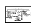
DN4)
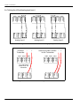
Figure 2: Sentinel LCT Ultrasonic Flow Transmitter Assembly for Pipes 14” to 36” dia. (ref. dwg #577-071)
Features and Capabilities
4
Chapter 1. Features and Capabilities
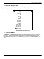
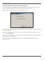
1.1.4 Name and Specification Plate
The location of the Sentinel LCT specification plate is shown in Figure 1 on page 3. Figure 3 below shows a blank
plate. The specifications can be filled in by the user, for quick reference while using the manual.
Tag #:
Order String:
Assembly Date:
S/N:
PO#:
SO#:
Meter Size:
ID:
Qmin /Q max :
HF Output:
Storage Temp:
Oper. Temp:
Oper. Pressure:
Test Pressure:
Hygro Test Date:
Flange Class:
Dry Weight:
Meter Body Material:
Flange Material:
Body Design Code:
Flange Design Code:
Type Approval Number:
Flow Cell Mfg:
Mfg Serial No:
NoBo ident. No:
Figure 3: Sentinel LCT Specification Plate
1.2 Theory of Operation
The Sentinel LCT Measurement System uses ultrasonic transit-time technology. A brief description of transit-time
theory follows. For more information about the the theory, and the use of GE Sensing ultrasonic flowmeters for
measuring flow, please refer to Ultrasoinc Measurements for Process Control by L.C. Lynnworth (Academic Press,
1989)
Sentinel LCT User’s Manual
5
Chapter 1. Features and Capabilities
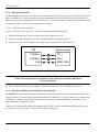
1.2.1 Transit-Time Method
The transit time technique uses a pair of transducers, with each transducer alternately sending and receiving coded
ultrasonic signals through the fluid. Figure 4 below shows the paths used in the Sentinel LCT. When the fluid is
flowing, signal transit time in the downstream direction is shorter than in the upstream direction; the difference
between these transit times is proportional to the flow velocity. The Sentinel LCT measures this very small time
difference and, using various digital signal processing techniques combined with programmed pipe parameters,
determines the flow rate and direction.
Figure 4: Path Configuration
1.2.2 Transducers
When in a transmit cycle, transducers convert electrical energy into ultrasonic pulses and then convert the ultrasonic
pulses back to electrical energy when in a receive cycle. In other words, they act like loudspeakers when transmitting
the signal and like microphones when receiving it. They perform the actual data transmission and collection, thus
interrogating the flow.
The transducers in the Sentinel LCT Measurement System were specifically designed to work with the available
Insertion Mechanism. In the event that a transducer becomes damaged or non-functional, it can be replaced without
shutting down the pipeline. The insertion mechanism is an option available with all offered versions of the Sentinel
LCT. To keep the fluid from escaping while the transducer is being replaced, it is recommended that a shutoff valve be
part of the original transducer holder assembly.
6
Sentinel LCT User’s Manual
Chapter 1. Features and Capabilities
1.2.3 Multipath Design
Multipath ultrasonic flowmeters are designed with more than one pair of transducers to interrogate the flow field in
different locations and more accurately determine the actual flowrate. The Sentinel LCT Measurement System uses
four measurement locations. These measurement paths are located across the meter body and tilted at an angle. The
four measurement paths are orthogonal to each other (see Figure 4 on page 6).
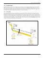
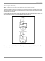
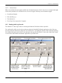
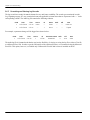
1.2.4 Flow Profile
One of the main factors affecting an ultrasonic flow measurement is the flow profile. If the flow profile is known,
mathematical modeling of the flow and the relationships between the paths' raw data can be made. This justifies the
required use of a flow-conditioning device with this system. A simulation example of how the flow conditioner reduces
secondary flow is shown in Figure 5 below. Maintaining a constant flow-profile shape across all flow velocities, pipe
sizes and upstream flow disturbances is difficult. For this reason, the factory has tested the Sentinel LCT under various
conditions in an effort to determine its operational limits.
5D
10 D
Flow Conditioner
Figure 5: Using a Flow Conditioner to Influence Flow Profile
Sentinel LCT User’s Manual
7
Chapter 1. Features and Capabilities
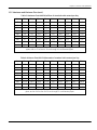
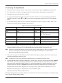
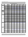
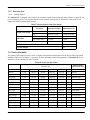
1.2.5 Maximum and Minimum Flow
Maximum and minimum flow rates through the Sentinel LCT Ultrasonic Liquid Flow Transmitter are based on the pipe
diameter and the process fluid pressure. The information in the following tables is approximate, and is based on
representative liquid components at a process temperature of 70°F (21°C). See Table 3 and Table 4 below for English
units and Table 5 and Table 6 on page 9 for metric units.
Table 3: Maximum Flow MMSCF (millions of standard cubic feet) per Day
psig
6”
8”
10”
12”
14”
16”
18”
20”
24”
100
16.2
28.0
44.2
47.3
57.2
74.7
94.5
117.5
169.9
200
30.7
53.2
83.9
89.8
108.6
141.8
179.5
223.1
322.6
400
61.1
105.9
166.8
178.6
215.9
282.0
357.0
443.6
641.6
600
93.3
161.5
254.6
272.6
329.5
430.4
544.8
677.0
979.1
800
127.3
220.4
347.4
371.9
449.4
587.1
743.2
923.4
1335.6
1000
163.0
282.2
444.9
476.3
575.6
751.9
951.8
1182.7
1710.5
1200
200.3
346.8
546.7
585.3
707.3
924.0
1169.6
1453.3
2102.0
1400
238.8
413.6
651.9
697.9
843.5
1101.9
1394.7
1733.1
2506.6
1480
254.5
440.7
694.7
743.7
898.8
1174.1
1486.2
1846.8
2671.0
Maximum flow rates are based on 118 ft/sec flow velocity for 6” through 10” diameter pipes,
and on 89 ft/sec for 12” through 24” diameter pipes.
Table 4: Minimum Flow MMSCF (millions of standard cubic feet) per Day
psig
6”
8”
10”
12”
14”
16”
18”
20”
24”
100
0.3
0.6
0.9
0.8
1.0
1.2
1.6
2.0
2.8
200
0.6
1.1
1.7
1.5
1.8
2.4
3.0
3.7
5.4
400
1.2
2.1
3.3
3.0
3.6
4.7
5.9
7.4
10.7
600
1.9
3.2
5.1
4.5
5.5
7.2
9.1
11.3
16.3
800
2.5
4.4
6.9
6.2
7.5
9.8
12.4
15.4
22.2
1000
3.3
5.6
8.9
7.9
9.6
12.5
15.8
19.7
28.4
1200
4.0
6.9
10.9
9.7
11.8
15.4
19.4
24.2
35.0
1400
4.8
8.3
13.0
11.6
14.0
18.3
23.2
28.8
41.7
1480
5.1
8.8
13.9
12.4
14.9
19.5
24.7
30.7
44.4
Minimum flow rates are based on 2.36 ft/sec flow velocity for 6” through 10” diameter pipes,
and on 1.48 ft/sec for 12” through 24” diameter pipes.
8
Sentinel LCT User’s Manual
Chapter 1. Features and Capabilities
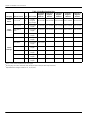
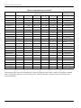
1.2.5 Maximum and Minimum Flow (cont.)
Table 5: Maximum Flow MMSCM (millions of standard cubic meters) per Day
bar
15cm
20cm
25cm
30cm
36cm
41cm
46cm
51cm
61cm
7
0.5
0.8
1.3
1.3
1.6
2.1
2.7
3.3
4.8
14
0.9
1.5
2.4
2.5
3.1
4.0
5.1
6.3
9.1
28
1.7
3.0
4.7
5.1
6.1
8.0
10.1
12.6
18.2
41
2.6
4.6
7.2
7.7
9.3
12.2
15.4
19.2
27.7
55
3.6
6.2
9.8
10.5
12.7
16.6
21.0
26.1
37.8
69
4.6
8.0
12.6
13.5
16.3
21.3
27.0
33.5
48.4
83
5.7
9.8
15.5
16.6
20.0
26.2
33.1
41.2
59.5
96
6.8
11.7
18.5
19.8
23.9
31.2
39.5
49.1
71.0
102
7.2
12.5
19.7
21.1
25.5
33.2
42.1
52.3
75.6
Maximum flow rates are based on 36 m/sec flow velocity for 15 cm through 25 cm diameter
pipes, and on 27 m/sec for 30 cm through 61 cm diameter pipes.
Table 6: Minimum Flow MkSCM (thousands of standard cubic meters) per Day
bar
15cm
20cm
25cm
30cm
36cm
41cm
46cm
51cm
61cm
7
9.2
15.9
25.0
22.3
26.9
35.2
44.5
55.3
80.0
14
17.4
30.1
47.5
42.3
51.1
66.8
84.5
105.0
151.9
28
34.6
59.9
94.5
84.1
101.7
132.8
168.1
208.9
302.1
41
52.8
91.5
144.2
128.4
155.1
202.7
256.5
318.8
461.0
55
72.1
124.8
196.7
175.1
211.6
276.5
349.9
434.8
628.9
69
92.3
159.8
251.9
224.3
271.0
354.1
448.2
556.9
805.5
83
113.4
196.4
309.6
275.6
333.1
435.1
550.7
684.3
989.8
96
135.3
234.2
369.2
328.6
397.2
518.9
656.8
816.1
1180.3
102
144.1
249.6
393.4
350.2
423.2
552.9
699.8
869.6
1257.8
Minimum flow rates are based on 0.72 m/sec flow velocity for 15 cm through 25 cm diameter
pipes, and on 0.45 m/sec for 30 cm through 61 cm diameter pipes.
Sentinel LCT User’s Manual
9
Chapter 1. Features and Capabilities
1.3 Specifications
The system specifications for the Sentinel LCT Ultrasonic Liquid Flow Transmitter are divided into the following
categories:
1.3.1 Operation and Performance
Note: The Sentinel LCT has been designed to meet the OIML R117-1, MID MI-005 and API MPMS 5.8 requirements.
1.3.1a
Fluid Types
Liquid Hydrocarbons
1.3.1b
Flow Measurement
Correlation Transit Time mode
1.3.1c
Accuracy
< ± 0.15% of measured volume for flow rates between 3 and 30 ft/s.
1.3.1d
Uncertainty
< ±0.027% according to API MPMS 5.8
1.3.1e
Zero Stability
< 0.003 ft/s
1.3.1f
Viscosity Range
0 to 500 cSt
Consult factory for higher Reynolds numbers.
1.3.1g
Reynolds Range
> Re 5.000
Consult factory for lower Reynolds numbers.
1.3.1h
Process Temperature
–40° to +120°C (–40° to +248°F) Standard
–200° to +120°C (–328° to +248°F) LNG
–200° to +600°C (–328° to 1112°F) Extended Range (consult factory)
1.3.1i
Ambient Temperature
–40° to +60°C
1.3.1j
Storage Temperature
–40° to +70°C
10
Sentinel LCT User’s Manual
Chapter 1. Features and Capabilities
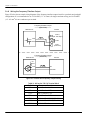
1.3.2 Meter Body
1.3.2a
Path Configuration
4 path Gaussian Quadrature
1.3.2b
Meter Body Materials
•
Carbon steel A105/A350LF2
•
Stainless steel A182, Gr 304/304L
•
Stainless steel A182, Gr 316/316L
Others on request.
1.3.2c
Flowcells
4” (100 mm) to 36” (900 mm)
Others on request.
C
A
Figure 6: Flowcell Assembly
Note: Use Figure 6 above to identify the A and C measurements in Table 7 on page 12.
Sentinel LCT User’s Manual
11
Chapter 1. Features and Capabilities
Note: Flowcells (cont.)
Table 7: Flowcell Dimensions
Dimensions and Weights in English Units
Diameter
(inches)
4
6
8
10
12
14
16
18
20
24
12
Flange
Weight (lb)
A (in)
C (in)
Weight (lb)
150
20
23.49
149
300
20
23.99
176
600
20
24.365
150
22
300
Dimensions and Weights in Metric Units
Diameter
(inches)
Flange
Weight (kg)
A (mm)
C (mm)
Weight (kg)
56
508
597
68
112
508
609
80
200
224
508
619
91
25.76
209
56
559
654
95
24
26.51
265
112
610
673
120
600
26
27.26
338
224
660
692
153
150
26
27.59
268
56
660
701
122
300
28
28.34
343
112
711
720
156
600
30
29.09
452
224
762
739
205
150
28
29.84
367
56
711
758
166
300
30
30.59
487
112
762
777
221
600
32
31.84
739
224
813
809
335
150
30
32.59
478
56
762
828
217
300
32
33.34
681
112
813
847
309
600
36
34.09
957
224
914
866
434
150
36
34.09
790
56
914
866
358
300
38
35.09
1079
112
965
891
489
600
40
35.465
1339
224
1016
901
607
150
38
36.84
989
56
965
936
449
300
40
37.84
1348
112
1016
961
611
600
42
38.59
1770
224
1067
980
803
150
38
37.84
1056
56
965
961
479
300
40
39.34
1527
112
1016
999
693
600
44
39.965
2076
224
1118
1015
942
150
46
41.25
1424
56
1168
1048
646
300
48
42.75
2120
112
1219
1086
962
600
50
41.25
2819
224
1270
1105
1280
150
48
44.59
1990
56
1219
1133
903
300
50
46.59
2947
112
1270
1183
1337
600
52
47.09
3946
224
1321
1196
1790
4
6
8
10
12
14
16
18
20
24
Sentinel LCT User’s Manual
Chapter 1. Features and Capabilities
1.3.2c Flowcells (cont.)
Table 8: Component Materials
Component
Material
Pipe Flanges and Fittings
Carbon Steel (A105 or A350 LF2*)
Pipe Sections
Carbon Steel (A106 Gr. B or A333 Gr. 6*)
Transducer Holder Components
Stainless Steel 316/316L (A276)
T11 Transducer
Titanium CP Gr. 2 (B348/B381)
*A350 LF2 and A333 Gr. 6 are used for low temperature service and are specified by the customer.
1.3.2d
•
150 #
•
300 #
•
600#
Flange Ratings
Others on request.
1.3.2e
Pipe Schedules
•
40S/STD
•
80S/XS
Others on request.
1.3.2f
•
PED Compliance
PED Cat III, Module H
1.3.2g
Installation Requirement
The meter must be installed with 20D straight piping upstream and 5D straight piping downstream. Inlet and outlet
piping shall match the meter ID within 1%. In case a 20D inlet cannot be mounted, a 10D inlet with tube bundle flow
conditioned could be applied. Pressure, temperature and density connections must be located in the downstream piping.
The 20D upstream piping (or 10D with flow conditioner) must be free of items that could disturb the flow profile.
Sentinel LCT User’s Manual
13
Chapter 1. Features and Capabilities
1.3.3 Electronics
1.3.3a
Electronics Enclosure Material
Epoxy-coated aluminum
1.3.3b
Weight
25 lb.
1.3.3c
Dimensions
Size (lxhxd): 13” x 11” x 9”
1.3.3d
Ingress Protection
•
USA / Canada: Type 4
•
Europe: IP66
1.3.3e
Power Supply
•
100 - 240 VAC
•
12 - 32 VDC
1.3.3f
Power Consumption
7 Watts
1.3.3g
Display
High contrast 128 x 64 pixel graphical display with LED illumination.
1.3.3h
Outputs
•
Two frequency/pulse outputs optically insulated from DC
•
Two alarm relays
•
One 4/20 mA output with HART
1.3.3i
Inputs
Two 4/20 mA and one 100 Ohm RTD input for density, pressure and temperature input (optional), or
Three 4/20 mA inputs for density, pressure and temperature input (optional).
1.3.3j
Digital Interfaces
•
HART over 4/20 mA output
•
PanaLink over RS232/485/USB
•
Modbus over RS232/485 (optional)
14
Sentinel LCT User’s Manual
Chapter 1. Features and Capabilities
1.3.3k
Flow Computer Functionality
Integrated flow computer with full P and T volume corrections according to API 11.1
1.3.3l
Hazardous Area Classification
•
USA / Canada:
Class I, Division 1, Groups B, C & D; T6
Class II and III, Division 1, Groups E, F & G; T6
Ta = –40°C to +60°C
Enclosure Type 4X & IP66
•
Europe:
ATEX and IECEx:
II 2 G Ex d IIB + H2, T6 IP66
II 2 D Ex tD A21 IP66 T85C
Ta = –40°C to +60°C
1.3.3m CE Marking Compliance
•
2006/95/EC Low Voltage Directive
•
97/23/EC Pressure Equipment Directive
1.3.3n
LVD Directive Compliance
2006/95/EC
1.3.4 Custody Transfer Approvals
1.3.4a
USA / Canada
Compliant with API MPMS 5.8
1.3.4b
Europe
MID MI-005 by Nmi (pending)
1.3.4c
Rest of World
OIML R117-1 by Nmi (pending)
Note: The Custody Transfer approvals are valid for the flowmeter only. These approvals are not applicable for the
built-in flow computer.
Sentinel LCT User’s Manual
15
Chapter 1. Features and Capabilities
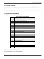
1.3.5 Ordering Information
1.3.5a
Sentinel Electronics SEN898
Table 9 below shows how the Sentinel LCT Electronics SEN898 part numbers are configured from the options
specified.
A
-
SEN898
-
B
-
C
- D -
-
E
-
F
-
- G
-
Table 9: Sentinel LCT Electronics Ordering Information
LTR
CATEGORY
B
Power
C
Inputs
D
Communications
E
Flow Computer
F
Certifications
G
Special
Requirements
16
OPTIONS
1 = 100 to 240 VAC operating voltage
2 = 12 to 32 VDC operating voltage
0 = None
1 = One 100 Ohm RTD input; Two 4-20mA inputs
2 = Three 4-20mA inputs
0 = None
1 = Modbus RTU over RS232/RS485
0 = None
API = API correction of volume per API Chapter 11.1 (3 inputs required)
1 = N. America Explosion Proof, Class 1, Div 1, groups B, C and D
2 = European Flame Proof, II 2G Ex d IIC
3 = European Flame Proof increased safety, II 2G Ex de IIC
0 = None
S = Special
Sentinel LCT User’s Manual
Chapter 1. Features and Capabilities
1.3.5b
Sentinel LCT Liquid Custody Transfer Flowmeter
Table 10 below shows how the Sentinel LCT Flow Section part numbers are configured from the options specified.
A
-
B
-
TE03 -
-
C
- D -
-
E
-
F
- G - H -
-
I
-
-
J
-
Table 10: Sentinel LCT Flow Section Ordering Information
LTR
CATEGORY
B
Nominal Size
C
Pressure Class
D
Material
E
Schedule
F
Design Criteria
G
Electronics
Mounting
H
Material Certs
I
Nace
Requirements
J
Special
Requirements
Sentinel LCT User’s Manual
OPTIONS
4 = 4”
10 = 10”
16 = 16”
6 = 6”
12 = 12”
18 = 18”
8 = 8”
14 = 14”
20 = 20”
150 = 150 lbs pressure rating
24 = 24”
28 = 28”
30 = 30”
32 = 32”
36 = 36”
300 = 300 lbs pressure rating
600 = 600 lbs pressure rating
CS = Carbon Steel, A105/A350LF2
304 = Stainless Steel, A182 Grade 304/304L
316 = Stainless Steel, A182 Grade 316/316L
40S/STD = Schedule size 40S/STD
80S/XS = Schedule size 80S/XS
S = Special
A = ASME B31.3
P = ASME B31.3 with PED approval
L = Integrated Local Mounting
S = Remote Mounting, cable length selectable (max 300 ft)
0 = None
1 = Material Certs
2 = Material certs with EN 10204 3.1 inspection certificate
0 = None
1 = NACE MR0175
2 = NACE MR0103
0 = None
S = Special
17
Chapter 1. Features and Capabilities
1.4 Disclaimer
The warranties set forth herein are exclusive and are in lieu of all other warranties whether statutory,
express or implied (including warranties of merchantability and fitness for a particular purpose, and
warranties arising from course of dealing or usage or trade).
1.5 Warnings and Cautions
WARNING! The Sentinel Flow Measurement System can measure the flow rate of many fluids, some of
which are potentially hazardous. The importance of proper safety practices cannot be
overemphasized.
Be sure to follow all applicable local safety codes and regulations for installing electrical
equipment and working with hazardous gases or flow conditions. Consult company safety
personnel or local safety authorities to verify the safety of any procedure or practice.
!ATTENTION EUROPEAN CUSTOMERS!
To meet CE Mark requirements, all cables must be installed as described in Appendix B,
CE Mark Compliance.
WARNING! Always disconnect the line power from the meter before removing either the front cover or the
side cover. This is especially important in a hazardous environment.
WARNING! Improper connection of the line power leads or connecting a Sentinel to the incorrect line
voltage may damage the unit. It may also result in hazardous voltages at the meter body and
associated piping as well as within the electronics enclosure.
WARNING! Make sure the front and side covers, along with their O-ring seals, are installed on the
transmitters, and the set screws tightened before applying power in a hazardous environment.
WARNING! Never remove the flowmeter covers in a hazardous environment while the line power is on.
18
Sentinel LCT User’s Manual
Chapter 2. Installation
Chapter 2.
Installation
2.1 Installation Guidelines
This section provides general information with respect to the mechanical and electrical installation, and should be
thoroughly reviewed before the system is installed. To ensure safe and reliable operation of the Sentinel LCT, the
system must be installed in accordance with the guidelines established by GE Sensing, as explained in this chapter.
WARNING! The Sentinel LCT Ultrasonic Liquid Flow Transmitter can measure the flow rate of many liquids,
some of which are potentially hazardous. The importance of proper safety practices cannot be
overemphasized.
Be sure to follow all applicable local safety codes and regulations for installing electrical
equipment and working with hazardous liquids or flow conditions. Consult company safety
personnel or local safety authorities to verify the safety of any procedure or practice.
!ATTENTION EUROPEAN CUSTOMERS!
To meet CE Mark requirements, all cables must be installed as described in Appendix B,
CE Mark Compliance.
2.2 Bill of Materials
The following items should have been included in the shipment:
•
Sentinel LCT flowspool
•
Sentinel SEN898 electronics
•
Magwand
•
User’s Manual
•
CD with PanaView Software
Sentinel LCT User’s Manual
19
Chapter 2. Installation
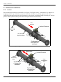
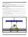
2.3 Mechanical Installation
2.3.1 Location
For both uni-directional and bi-directional flow (see Figure 7 and Figure 8 below), a minimum of five diameters of
straight pipe shall be provided by the customer on either side of the meter run, directly upstream of the flow
conditioning plate and downstream of any disturbances or pipe bends. An additional length of straight pipe will help
produce a more symmetrical flow profile, thus reducing the measurement uncertainty.
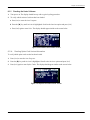
Flow
Direction
Sentinel Flowmeter
Flow
Conditioning
Plate
Ten-DiameterLong Spoolpiece
Five Diameters
of Straight Pipe
(minimum)
Figure 7: Typical Sentinel LCT Installation, Uni-Directional Flow
Flow Direction
Flow
Conditioning
Plate
Sentinel Flowmeter
Flow
Conditioning
Plate
Five Diameters
of Straight Pipe
(minimum)
Five Diameters
of Straight Pipe
(minimum)
Figure 8: Typical Sentinel LCT Installation, Bi-Directional Flow
20
Sentinel LCT User’s Manual
Chapter 2. Installation
2.3.2 Installation Precautions
Any questions with respect to the installation should be addressed prior to beginning the installation. Failure to install
the Sentinel LCT correctly can increase measurement uncertainty.
CAUTION!
To avoid possible strain, refer to the Sentinel LCT label for the assembly weight, use a
properly-rated lifting assembly, and place the lifting straps in the indicated locations (see
Figure 9 below).
All the mechanical and electronic components are shipped fully assembled (see Figure 1 on page 3), however the
following precautions should be observed:
•
Make sure the difference between the inside diameter of the pipe and that of the Sentinel LCT spoolpiece does not
exceed 1%. (Changes in internal diameters will cause flow profile disturbances.)
•
Make sure any non-symmetrical offset does not exceed 1%. (Misalignment between the piping and the spoolpiece
may cause flow profile disturbances.)
•
Make sure the gasket is centered on the flange faces and does not protrude into the pipe. (Protrusion of the gasket
into the pipe may cause flow profile disturbances.)
•
Make sure the Sentinel LCT is oriented with the flow transmitter in a vertical position at the top (see Figure 9
below).
Figure 9: Lifting Strap Locations
Sentinel LCT User’s Manual
21
Chapter 2. Installation
2.3.3 Installing the System
Being mindful of Installation Precautions listed on page 21, complete the following steps:
1. Make sure the gaskets are in place on the flanges.
2. Support the Sentinel LCT between the flanges on the pipe.
3. Align the flange mounting holes (see Figure 10 below).
4. Secure the spoolpiece to the pipe by using the appropriate hardware.
Figure 10: Sentinel End View - Mounting Flange
2.3.4 Guidelines for Installing Pipe Insulation
If pipe insulation is required:
1. Install all insulation materials and accessories in accordance with the manufacturer's instructions and the
recognized industry practices. Adhere to the local code where applicable to ensure that the safe and proper
installation will serve its intended purpose.
2. Install the insulation material in layers, with smooth and even surfaces. Allow adequate space (air pockets) around
all extended transducer buffer rods, conduit fittings, junction boxes, and cables, for proper ventilation. Avoid using
cut pieces or scrap insulation when abutting the sections being installed. Butt insulation joints firmly to ensure a
complete, tight fit over and around all piping surfaces.
3. Maintain the integrity of any factory-applied vapor barrier jacketing on all pipe insulation, if applicable. Seal all
joints and seams, protecting the insulation against puncture, tears or other damage.
22
Sentinel LCT User’s Manual
Chapter 2. Installation
2.4 Making Electrical Connections
This section contains instructions for making the necessary electrical connections to the flow transmitter (see Figure 11
below). The wiring between transmitter and transducers has been accomplished at the factory. No further work is
required on this portion of the wiring.
IMPORTANT: When wires are connected to terminal blocks, use wire ties routed through the blocks, to secure them.
!ATTENTION EUROPEAN CUSTOMERS!
To meet CE Mark requirements, all cables must be installed as described in Appendix B,
CE Mark Compliance.
IMPORTANT: The meter spoolpiece is grounded to the electronics. This configuration must be considered when
applying cathodic protection to the pipe line. The power ground applied to the instrument should be at
the cathodic protection voltage level.
Power
2 Frequency
2 Alarms
1 Analog Output (4-20 mA) with HART
3 Analog Inputs (4-20 mA) or
2 Analog Inputs (4-20 mA) +
1 RTD Input
Flow
RS232/RS485 Modbus Computer
RS232
or
RS485
Pressure
Corrected
Volumetric
Flow
Temperature
SentinelSentinel LCT
Meter Calibration, Data Collection,
Configuration, and Security
PanaView™
Instrument Interface
Software
Figure 11: Sentinel LCT Flow Measurement System Connections
Sentinel LCT User’s Manual
23
Chapter 2. Installation
2.4.1 Removing the Covers
WARNING! Always disconnect the line power from the meter before removing either the front display cover
or the wiring access cover. This is especially important in a hazardous environment.
1. Disconnect any previously wired power line from the flow transmitter.
2. Loosen the set screw on the side cover using a 2.5 mm hex wrench.
3. Place a rod or long screwdriver across the cover in the slots provided, and rotate the cover counterclockwise until it
comes free from the enclosure.
4. Note the text imprinted on the terminal board (see Figure 12 below) to assist in wiring the power and option card
connections.
Proceed to the appropriate section of this chapter to make the desired wiring connections.
L1 L2/N G
Figure 12: Terminal Board with Imprinted Text (Three 4-20mA Input Options)
24
Sentinel LCT User’s Manual
Chapter 2. Installation
2.4.2 Cable Tie-Down Posts
There are two cable tie-down posts provided in the Sentinel LCT (see Figure 13 below). These posts enable the user to
insert a cable tie through them, and secure wiring coming into or out of the instrument. The posts rotate on the printed
circuit board to provide ease-of-use.
•
Power Cable Tie-Down Post - Use this tie-down post to secure the instrument power securely.
•
Optional I/O Cable Tie-Down Post - Use this optional tie-down post to secure any other instrument I/O securely.
Optional I/O Cable
Tie-Down Post
Power Cable
Tie-Down Post
Figure 13: Cable Tie-Down Posts Locations
Sentinel LCT User’s Manual
25
Chapter 2. Installation
2.4.3 Wiring the Line Power
The Sentinel LCT may be ordered for operation with a power input of 100-240 VAC or 12–32 VDC (see the
Electronics Ordering Information in Table 9 on page 16). The label on the side of the electronics enclosure lists the
required line voltage and power rating. The fuse size is listed in Specifications in Chapter 1. Be sure to connect the
Sentinel LCT to the specified line voltage only.
Note: For compliance with N. American and European Low Voltage Directive (2006/95/EC), this unit requires an
external power disconnect device such as a switch or circuit breaker. The disconnect device must be marked as
such, clearly visible, directly accessible, and located within 1.8 m (6 ft) of the unit.
Note: Use one conduit inlet for power. Use the two other conduit inlets for input/output as needed. All unused conduit
inlet ports should be sealed with suitable blanking elements.
See Figure 15 on page 27 to locate terminal block TB1 and to connect the line power as outlined below:
WARNING! Improper connection of the line power leads, or connecting a Sentinel LCT to the incorrect line
voltage, may damage the unit. It may also result in hazardous voltages at the meter body and
associated piping as well as within the electronics enclosure.
1. Prepare the line power leads by trimming the line and neutral AC power leads (or the positive and negative DC
power leads) to a length 0.5 in. (1 cm) shorter than the ground lead. This ensures that the ground lead is the last to
detach if the power cable is forcibly disconnected from the meter.
Figure 14: Conduit Inlet Ports
2. Route the cable through one of three conduit inlet ports (see Figure 14 above) and connect the line power leads to
terminal block TB1, using the pin number assignments shown in Figure 29 on page 38 and Figure 15 or Figure 16
on page 27.
!ATTENTION EUROPEAN CUSTOMERS!
To meet CE Mark requirements, all cables must be installed as described in Appendix B,
CE Mark Compliance.
26
Sentinel LCT User’s Manual
Chapter 2. Installation
2.4.3 Wiring the Line Power (cont.)
Note: All wires shall have a temperature/type rating 10K above the maximum service temperature of 85°C, be
stripped back 5/16 in. (8 mm) and torqued to a minimum of 4.4 in. lb. (0.5 Nm).
3. Run the AC power connections to the Power Terminal Block shown in Figure 15 below. It is recommended to use
12-18 AWG (3.3 - 0.82 mm2) power wiring.
4. Strip 1/4-in. of insulation from the end of each of the three line power leads.
5. Route the cable through the chosen conduit hole and connect the line power leads to terminal block TB1, using the
pin number assignments shown in Figure 30 on page 39 and Figure 15 or Figure 16 below.
6. Leaving a bit of slack, secure the power line with the cable clamp.
WARNING! Make sure the front and side covers, along with their O-ring seals, are installed on the
transmitters, and the set screws tightened before applying power in a hazardous environment.
7. Once the line power has been connected to the flow transmitter, replace the side cover, tighten the set screw using a
2.5 mm hex wrench, and proceed to the next section.
L1 L2/N G
Figure 15: Wiring the AC Line Power
Figure 16: Wiring the DC Line Power
Sentinel LCT User’s Manual
27
Chapter 2. Installation
2.4.4 Wiring the Serial Port
The flow transmitter is equipped with a built-in serial communications port. This port is user-selectable to be either an
RS232 or RS485 port. For more information on serial communications refer to the EIA-RS Serial Communications
Manual (916-054). It is recommended to use 12-24 AWG (3.3 - 0.2 mm2) twisted pair wiring for single conductors, and
a minimum 18 AWG (1.5 mm2) for two conductors per terminal.
2.4.4a
Wiring the Serial Interface
To wire the serial port, refer to Figure 30 on page 39 and complete the following steps:
1. Disconnect the main power to the meter and remove the wiring access cover.
2. Install the required cable gland in the chosen conduit hole of the electronics enclosure.
3. Feed one end of the cable through the cable gland, wire it to terminal block TB2, and secure.
TB2
Network Interface
T (RS485–)
TD (–)
R (RS485+)
RD (+)
COM
SGND (COM)
Figure 17: Serial Connections
!ATTENTION EUROPEAN CUSTOMERS!
To meet CE Mark requirements, all cables must be installed as described in Appendix B,
CE Mark Compliance.
4. If the wiring of the unit has been completed, reinstall the wiring access cover and tighten the set screw.
2.4.5 Wiring the Modbus Communications Line (Optional)
The Sentinel LCT uses the RS485 interface with Modbus communications protocol for a maximum line distance up to
4,000 ft (1,200 m). The factory recommends using shielded 18-24 AWG (0.82 - 0.2 mm2)) cable having a characteristic
impedance of 120 ohms, with 120-ohm termination at each end of the communications line. This interface is also
user-configurable as an RS232 interface.
Connect the two leads and the shield of the Modbus line to the NET section of terminal block TB2 in the flowmeter.
See Figure 12 on page 24, Table 11 on page 34 and Figure 30 on page 39.
28
Sentinel LCT User’s Manual
Chapter 2. Installation
2.4.6 Wiring the Alarm Relay
Note: The alarm relay can be wired as either Normally Open (NO) or Normally Closed (NC).
An alarm relay should be wired for fail-safe operation. In fail-safe mode, the alarm relay is constantly energized, except
when it is triggered, or a power failure or other interruption occurs. See Figure 18 below for the operation of a normally
open alarm relay in fail-safe mode.
Connect the alarm relay in accordance with the wiring instructions shown on the terminal board label (see Figure 12 on
page 24 and Figure 28 on page 37). For a wiring diagram see Figure 30 on page 39.
Fail-Safe
(not triggered)
NO
C
NC
ALARM
MONITORING
DEVICE
Fail-Safe
(triggered or power failure)
NO
C
NC
ALARM
MONITORING
DEVICE
Figure 18: Fail-Safe Operation
It is recommended to use 12-24 AWG (3.3 - 0.2 mm2) for single conductor wiring, and 16-24 AWG (1.5 - 0.2 mm2) for
two conductors per terminal.
Sentinel LCT User’s Manual
29
Chapter 2. Installation
2.4.7 Wiring the 4-20mA Analog Input (Optional)
1. Disconnect the main power to the flowmeter and remove the wiring access cover.
2. Install a cable gland in the chosen conduit hole of the electronics enclosure and feed a standard twisted-pair cable
through this conduit hole.
3. Locate the 26-pin terminal block (TB2) in Figure 28 on page 37 and wire the I/O terminal as indicated on the label
inside the wiring access cover (see Figure 12 on page 24 and Figure 28 on page 37). For a wiring diagram, see
Figure 30 on page 39.
4. Secure the cable clamp.
!ATTENTION EUROPEAN CUSTOMERS!
To meet CE Mark requirements, all cables must be installed as described in Appendix B,
CE Mark Compliance.
5. If wiring of the unit has been completed, reinstall the side cover on the enclosure and tighten the set screw.
The analog input option provides either three isolated 4-20mA analog inputs, or two isolated 4-20mA analog inputs
and one RTD input (designated Ain1, Ain2, Ain3 and RTD1). Each of the 4-20 inputs includes a 24 VDC power supply
for loop-powered transmitters. The inputs may be used to process temperature, density and pressure signals.
Note: To enter programming data during operation of the Sentinel LCT, it will be necessary to know which input is
assigned to which process parameter. This information should be entered in Appendix C, Data Records.
The analog inputs, which have an impedance of 118 ohms, should be connected with standard twisted-pair wiring.
Power to the transmitters may be supplied either by the internal 24 VDC power supply on the analog input terminal or
by an external power supply. Figure 19 on page 31 shows typical wiring diagrams, with and without an external power
supply, for one of the analog inputs. Figure 20 on page 31 shows 4-wire RTD input wiring. Wire the analog inputs as
shown on the label in the enclosure side cover (see Figure 12 on page 24 and Figure 28 on page 37). Terminal locations
are shown in Figure 21 on page 32 through Figure 24 on page 33.
It is recommended to use 12-24 AWG (3.3 - 0.2 mm2) for single conductor wiring, and 16-24 AWG (1.5 - 0.2 mm2) for
two conductors per terminal.
30
Sentinel LCT User’s Manual
Chapter 2. Installation
2.4.7 Wiring the 4-20mA Analog Input (cont.)
With External Power Supply
24 VDC
POWER SUPPLY
–
+
Transmitter
Analog Input
+ IN
Ain RTN
Ain
Sensor
– OUT
+24V
With Internal Power Supply
Analog Input
Transmitter
Ain RTN
– OUT
Ain
Sensor
+ IN
+24V
Figure 19: Analog Input Wiring Diagram
TB2/RTD1
CUR
+S
RTD
–S
RTN
Figure 20: 4-Wire RTD Input Wiring Diagram
Sentinel LCT User’s Manual
31
Chapter 2. Installation
2.4.7 Wiring the 4-20mA Analog Input (cont.)
AIN3
AIN2 AIN1
AIN3 AIN2
AIN3 AIN2 AIN1
RTN1
+24V1
AIN1
+24V2
AIN2
+24V3
AIN3
+24V1
AIN1
+24V2
AIN2
+24V3
AIN3
+24V1
AIN1
+24V2
AIN2
+24V3
AIN3
Analog Input 2
RTN1
RTN2
RTN2
RTN3
RTN3
RTN1
RTN1
RTN2
RTN2
RTN3
RTN3
RTN1
RTN1
RTN2
RTN2
RTN3
RTN3
Analog Input 1
AIN1
Analog Input 3
Figure 21: Terminal Locations for 3 Analog Input Option
Powered
Transmitter
AIN3
–
AIN2
+
AIN1
Sentinel provides +24VDC
for the Transmitter
–
+
AIN3 AIN2 AIN1
RTN1
RTN1
RTN2
RTN2
RTN3
RTN3
RTN1*
RTN1*
RTN2
RTN2
RTN3
RTN3
*You can wire to
either RTN1 TB
connection.
+24V1
AIN1
+24V2
AIN2
+24V3
AIN3
+24V1
AIN1
+24V2
AIN2
+24V3
AIN3
Figure 22: Terminal Locations for Analog Transmitter Use Cases
32
Sentinel LCT User’s Manual
Chapter 2. Installation
RTD1 AIN2 AIN1
RTD1 AIN2 AIN1
RTN1
+24V1
AIN1
+24V2
AIN2
CUR
S+
+24V1
AIN1
+24V2
AIN2
CUR
S+
+24V1
AIN1
+24V2
AIN2
CUR
S+
Analog Input 2
RTN1
RTN2
RTN2
S–
RTN
RTN1
RTN1
RTN2
RTN2
S–
RTN
RTN1
RTN1
RTN2
RTN2
S–
RTN
Analog Input 1
RTD1 AIN2 AIN1
RTD Input 3
Figure 23: Terminal Locations for 2 Analog Input and 1 RTD Input Option
3-Wire RTD
4-Wire RTD
Current
Sense
Sense Return
Current
Sense
RTN
AIN2
Sense Return
Add
Jumper
AIN1
AIN2 AIN1
RTN1
RTN1
RTN2
RTN2
S–
RTN
RTN1*
RTN1*
RTN2
RTN2
S–
RTN
*You can wire to
either RTN1 TB
connection.
+24V1
AIN1
+24V2
AIN2
CUR
S+
+24V1
AIN1
+24V2
AIN2
CUR
S+
Figure 24: Terminal Locations for 4-Wire and 3-Wire RTD Use Cases
Sentinel LCT User’s Manual
33
Chapter 2. Installation
2.4.8 Wiring the Frequency/Totalizer Output
Figure 25 below shows sample wiring diagrams of the frequency/totalizer output circuit for open drain and push-pull
configurations. It is recommended to use 12-24 AWG (3.3 - 0.2 mm2) for single conductor wiring, and 16-24 AWG
(1.5 - 0.2 mm2) for two conductors per terminal.
Frequency/Totalizer Output
(Open Drain)
Sentinel LCT
Counter
Volts +
(Int. Pwr. Sup.)
OUT
Load
RTN
Volts (Common)
Frequency/Totalizer Output
(Push-Pull)
Sentinel LCT
Counter
+5V
270
OUT
IN
RTN
Common
Figure 25: Totalizer and Frequency Output Wiring
Table 11: Wiring the TB2 I/O Terminal Block
I/O Pin #
Function
34
F/T1+
Freq 1/Totalizer 1 OUT
F/T1–
Freq 1/Totalizer 1 RTN
F/T2+
Freq 2/Totalizer 2 OUT
F/T2–
Freq 2/Totalizer 2 RTN
NET R (+)
MODBUS–RTU RS232 (R)/RS485 (+)
NET T (–)
MODBUS–RTU RS232 (T)/RS485 (–)
NET COM
MODBUS–RTU Common
Sentinel LCT User’s Manual
Chapter 2. Installation
2.4.9 Wiring the 4-20 mA Analog Output
The standard configuration of the flow transmitter includes an isolated 4-20 mA analog output. Connections to this
output may be made with standard 12-24 AWG (3.3 - 0.2 mm2) twisted-pair wiring for a single conductor, and
16-24 AWG (1.5 - 0.2 mm2) for a two conductor, but the current loop impedance for these circuits must not exceed
1000 ohms. To wire the analog outputs, complete the following steps:
1. Disconnect the main power to the flowmeter and remove the enclosure side cover.
2. Install the required cable clamp in the chosen conduit hole on the side of the electronics enclosure.
3. Locate the 26-pin terminal block (TB2) shown in Figure 29 on page 38, and wire the I/O terminal as indicated on
the label inside the wiring access cover (see Figure 12 on page 24 and Figure 28 on page 37). For a wiring diagram
see Figure 26 or Figure 27 below.
4/20
Monitor
Aout + Flowmeter
Terminal
Board
Aout – Connector
Load
+
–
24 Volt DC
Power
Supply
Figure 26: Analog Output Passive Wiring
4/20
Monitor
Aout + Flowmeter
Load
Terminal
Board
Aout – Connector
Figure 27: Analog Output Active Wiring
Sentinel LCT User’s Manual
35
Chapter 2. Installation
2.4.9 Wiring the 4-20 mA Analog Output (cont.)
4. Secure the cable clamp.
!ATTENTION EUROPEAN CUSTOMERS!
To meet CE Mark requirements, all cables must be installed as described in Appendix B,
CE Mark Compliance.
5. If wiring of the unit has been completed, reinstall the wiring access cover on the enclosure and tighten the set
screw.
After the Sentinel LCT has been completely installed and wired, proceed to Chapter 3, Operation, to program the
flowmeter.
WARNING! Make sure both covers, with their o-ring seals, are installed, and the set screws tightened,
before applying power in a hazardous environment.
36
Sentinel LCT User’s Manual
Front Display
Sentinel LCT User’s Manual
Wiring Access Cover
Figure 28: SEN898 Electronics Enclosure - Front Display and Wiring Access Cover
Installation
37
–
+
COM
NC
NO
ALM2
J2
TB3
ALM1
TB1
RJ45
Ain3 Ain2 Ain1
USB
J1
I/O
TB2
in/R2
in/R2
in/R2
Tx
Rx
Com
Aout+
Aout–
F/T1+
F/T1–
Sentinel LCT User’s Manual
Figure 29: SEN898 Electronics Enclosure - Terminal Block Layout
Installation
38
Installation
(3) 3/4" NPT CABLE GLANDS PORTS
(CABLE ENTRY ON OPPOSITE SIDE OF ENCLOSURE)
MODBUS / TCP CONNECTOR (NON-IS ONLY)
(2) CABLE TIE DOWN POINTS
GROUNDING SCREWS FOR 2-WIRE
SHIELD CABLES (RECOMMENDED)
8-32 SCREW
MODBUS NETWORK RS232/485
T/MODBUS (TRANSMIT / DATA -)
R/+
MODBUS (RECEIVE / DATA +)
COM
MODBUS COMMON
(±15VDC, 200mA)
SEE NOTES 1 & 3
AC OPTION:
L1
LINE 1
L2/N LINE 2/NEUTRAL
G
GROUND
(264VAC, 0.82A)
SEE NOTES 2 & 3
DC OPTION:
+ (+)
(-)
GROUND
(30VDC, 2A)
SEE NOTES 2 & 3
DIGITAL INPUT
Din+
TOTALIZER GATE SIGNAL
Din RTN TOTALIZER GATE RETURN
(5VDC, 100mA)
SEE NOTES 1 & 3
–
COM
NC
NO
+
USB CONNECTOR (NON-IS ONLY)
(SERVICE USE ONLY)
ALM2
J2
TB3
ALM1
TB1
AIN3 AIN2 AIN1
NET
RTN1
RTN1
RTN2
RTN2
RTN3
RTN3
Din+
T (–)
Com
R (+)
F/T2–
F/T2+
USB
J1
NOTES:
1. I/O CONNECTIONS WIRE GAUGE RANGE 12-24 AWG (3.3 - 0.2 mm 2).
2. AC AND DC CONNECTIONS WIRE GAUGE RANGE 12-18 AWG (3.5 - .82 mm 2).
ALARM CONNECTORS
ALM1:
3. MAXIMUM TERMINAL RATINGS [VOLTAGE, CURRENT].
AIN1
NORMALLY OPENED
NORMALLY CLOSED
COMMON
AIN2
AIN3
T (-)
R (+)
Com
Aout+
Aout–
F/T1+
F/T1–
NO
NC
COM
I/O
TB2
ALM2:
NO
NORMALLY OPENED
NC
NORMALLY CLOSED
COM COMMON
AC (120VAC, 5A)
DC (28VDC, 5A)
SEE NOTES 1 & 3
FREQUENCY/TOTALIZER OUTPUT
F/T1+ OUTPUT1 SIGNAL
F/T1- OUTPUT1 RETURN
F/T2+ OUTPUT2 SIGNAL
F/T2- OUTPUT2 RETURN
(100VDC, 1A)
SEE NOTES 1 & 3)
CUSTOMER
GROUND
ANALOG OUTPUT
AOUT+ 4-20mA POS TERMINAL
AOUT- 4-20mA NEG TERMINAL
POWERED OR UNPOWERED
SOFTWARE SELECTABLE
SEE NOTES 1 & 3
Sentinel LCT User’s Manual
PANALINK RS232/485
T/TRANSMIT / DATAR/+
RECEIVE / DATA+
COM
COMMON
SEE NOTES 1 & 3
(3) ANALOG INPUTS OPTION (AAA)
ANALOG INPUT 1
AIN1
ANALOG IN
+24V1 24VDC
RTN1 24VDC RETURN
RTN1 ANALOG RETURN
(2) ANALOG INPUTS & RTD INPUT OPTION (AAR)
ANALOG INPUT 1
AIN1
ANALOG IN
+24V1 24VDC
RTN1 24VDC RETURN
RTN1 ANALOG RETURN
ANALOG INPUT 2
AIN2
ANALOG IN
+24V2 24VDC
RTN2 24VDC RETURN
RTN2 ANALOG RETURN
ANALOG INPUT 2
AIN2
ANALOG IN
+24V2 24VDC
RTN2 24VDC RETURN
RTN2 ANALOG RETURN
ANALOG INPUT 3
AIN3 ANALOG IN
+24V3 24VDC
RTN3 24VDC RETURN
RTN3 ANALOG RETURN
SEE NOTES 1 & 3
RTD INPUT 1
S+
SENSE +
CUR
CURRENT OUT
SSENSE RTN
CURRENT RETURN
SEE NOTES 1 & 3
Figure 30: SEN898 Electronics - Wiring Diagram (ref. dwg #702-884)
POWER CORD TERMINAL
39
Installation
FLOWCELL (REAR VIEW)
XDCR
UP4
XDCR
DN3
XDCR
UP2
CABLE, SINGLE
XDCR
DN1
JUNCTION BOX
JUNCTION BOX
FLOW
CABLE, DUAL
CABLES
CABLE, DUAL
PORT B
PORT C
SEN898 ELECTRONICS
TOP VIEW
UP1
UP2 UP3 UP4
FLOW PCB
DN1 DN2 DN3 DN4
PORT A
PORT D
CABLE, DUAL
CABLE, DUAL
CABLES
FLOW
JUNCTION BOX
JUNCTION BOX
XDCR
UP1
CABLE, SINGLE
XDCR
DN2
XDCR
Figure 31: Sentinel LCT to SEN898 Electronics - Interconnection Diagram (ref. dwg #702-887)
CABLE, SINGLE
CABLE, SINGLE
UP3
XDCR
DN4
FLOWCELL (FRONT VIEW)
Sentinel LCT User’s Manual
40
Chapter 3. General Programming
Chapter 3.
General Programming
3.1 Introduction
The Sentinel LCT flow transmitter includes a User Program that provides access to the various programmable features
of the instrument. This chapter describes step-by-step programming instructions using the internal keypad, shown in
Figure 32 below.
3.2 Keypad Features
Clear Totals
Power Indicator
Main Display
Fault Indicator
Total Lock Indicator
User Intervene
Keypad Lock
Indicator
Escape (Cancel)
Enter
Up, Left, Right,
and Down Arrows
Figure 1: Sentinel LCT Keypad
The Sentinel LCT has seven keys: a Clear Totals key, four arrow keys, an Escape
key, and an Enter key.
key to open the main menu on the display. (If locked, see Unlocking and Locking on page 44.)
•
Use the Escape
•
Use the arrow keys to navigate among menu choices and to increment/decrement numeric entries.
•
Use the Escape
•
Use the Enter
key to cancel a numeric entry change, or exit a menu.
key to accept a numeric entry or select a menu option.
Sentinel LCT User’s Manual
41
Chapter 3. General Programming
3.2.1 Indicator Lights
If the Fault Indicator is lit, an instrument fault is detected. An error indication will be displayed in the lower
right-hand corner of the Measurement View.
If the User Intervene Indicator is lit, an alarm has been triggered and will be kept latched until cleared by the user.
See Wiring the Alarm Relay on page 29 and Inputs/Outputs on page 55 for more information.
The Keypad Lock Indicator will be lit if the Keypad Lock-Out Switch, internal to the instrument, has been engaged.
Note: If the Keypad Lock Indicator is lit, the keypad will not be functional.
The Total Lock Indicator will be lit if the Totals Lock-Out Switch, internal to the instrument, has been engaged.
Note: If the Total Lock Indicator is lit, totals are not able to be reset by the Clear Totals Key or through programming.
The Power Indicator is normally lit when the instrument is powered.
3.2.2 The Magnetic Stylus
Each of the keys can be selected using a hand-held magnet called a Magnetic Stylus, which is included with the meter.
By touching the clear window at a key location, that key will be selected and will flash a red light to verify the contact.
Figure 2: Magnetic Stylus
42
Sentinel LCT User’s Manual
Chapter 3. General Programming
3.3 Program Menu Options
3.3.1 Channel Program
For the Channel Program setup, refer to the appropriate section for a discussion of the following PROG menu options,
beginning on page 47.
•
Status - activate or deactivate the channels/paths.
•
Fluid - enter Reynolds Correction data (not supported at this time).
•
Signal - enter the zero cutoff parameter.
•
Error Limits - enter minimum and maximum signal, velocity, amplitude and soundspeed.
3.3.2 Composite Program
For the composite program setup, refer to the appropriate section for a discussion of the following Composite menu
options, beginning on page 51.
•
Fluid - enter fluid type in normal or Tracking Windows Mode.
•
Signal - enter the number of errors allowed and the Compensation Status (additional option).
•
Inputs - enter the temperature, pressure and density parameters.
•
API Setup (additional option) - enter the table type and conditions.
3.3.3 Advanced Program
Note: The Advanced Program is accessible only to persons with Field Service, Factory or Engineering status.
For the advanced program setup, refer to Chapter 4, Advanced Programming.
•
Transducer - enter data for preprogrammed or special clamp-on transducers
•
K Factor - enter the Meter Correction (K) Factor as a single value or as a table of values
•
Pipe - enter pipe parameters
•
Weight Factors - enter the appropriate weight parameter.
To measure flow rate with the Sentinel LCT, activate the channel/path(s) and enter the transducer, pipe and fluid
parameters. Appendix A includes a complete set of menu maps for the User Program, including Figure 233 on
page 220 for the PROG menu.
Note: This manual describes the programming of Channel 1, only. To program Channels 2 through 4, simply repeat
the same procedures presented for Channel 1.
Sentinel LCT User’s Manual
43
Chapter 3. General Programming
3.4 Unlocking and Locking
To prevent unauthorized tampering with either the display or the user program, the Sentinel LCT has multiple security
codes. Once the security level has been set, one of these codes is required to change just the display (Display Lock), or
the display and the user program (Full Lock).
Note: To speed up the key response of the Sentinel LCT, deactivate CH1-CH4, as described on page 47. Remember to
reactivate the channels when programming is complete.
3.4.1 Unlocking the Sentinel LCT
To unlock the display and/or the user program:
1. Press [ESC], [ENT], [ESC]. A Security Check window, similar to Figure 34 below, appears.
Figure 3: Security Check Window
2. Using the arrow keys, change the code number to the value desired for your security level. The security passcodes
can be configured under USER EDIT PASSCODES when the user is logged in as User Admin.
Table 12: Default Passcodes
SECURITY LEVEL
PASSCODE
Full Lock
0000
Display Locked
2719
User 1
0001
User 2
0002
User 3
0003
User 4
0004
User Admin
0005
Field Service
----
Factory
----
Engineering/Unlock
----
3. Press [ENT]. The display screen reappears, with the lock removed, partially unlocked, or lettered to represent the
level. Security will remain at this level until you change the level in the user program, as described on the next
page, or if it times out and returns to full lock.
44
Sentinel LCT User’s Manual
Chapter 3. General Programming
3.4.2 Locking the Sentinel LCT
The security level can be accessed in two ways.
From the display screen:
1. Press the [] key three times, until the lock in the upper right corner is highlighted.
2. Press [ENT], and proceed to step 4 below.
From the User Program:
1. Press [ESC]. The Sentinel LCT enters the User Program.
2. Press the [] key until USER is bracketed.
3. Press the [] key until Set Security is highlighted. Press [ENT].
4. The screen shows up to ten options (depending on the current security level):
•
Full Lock – This will be the default level during meter power-up. Any User who wishes to access the menu will
have to press the keys in the following combination (Escape-Enter-Escape) to unlock the meter with a “Valid
Passcode”. The entered “Passcode” is validated and the user is allowed to access the menu based on privileges.
The meter will go back to Full-Lock mode if no keypad activity is noted for a “Determined Time”.
•
Display Locked – This level can be achieved by entering a “Valid Passcode” assigned for this role. In this
Mode/Level, the User has privilege only to view data. The User will be allowed to select the diaplay parameters.
Any other changeable parameter is denied access.
•
User-1 / User-2 / User-3 / User-4 – The User has to enter a “Valid Passcode” to have access to the menu attached
to this role. The User with this role will have rights of Display Locked mode and some predetermined “write
privilege” with which he may modify parameters (attached to this role).
•
User Admin – This User will have “Administrator privilege” in addition to privileges of Lower level. This user is
given the rights to change the “Passcode” for all user-levels. (This does not include Full Lock and Display
Locked). The Administrator has the privilege to modify the timeout value, which is used to determine the time
taken to switch back to Full Lock mode (if no keypad activity is noted). The “Administrator privilege” does not
include access to Service or Factory Menu. The Administrator has no rights or control on
Service/Factory/Engineering Levels or their “Passcodes”.
•
Field Service – This User has access to the “Service Menu” in addition to “Administrator privilege”. It is not
accessible by User Admin.
•
Factory – This User has access to “Factory privilege” in addition to “Service privileges”. It is not accessible by
User Admin.
•
Engineering – This User is the only user with Full access to the meter. Only this user has rights to change the
“Passcodes” for Factory and Service. It is not accessible by User Admin.
Sentinel LCT User’s Manual
45
Chapter 3. General Programming
3.4.2 Locking the Sentinel LCT (cont.)
Scroll to the desired option and press [ENT] twice.
5. Press [ESC] to return to the User Program, or continue pressing [ESC] to return to the display screen. If you have
chosen to fully lock the Sentinel LCT, the screen appears similar to Figure 35 below, with a solid lock in the upper
right corner. (For a meter with only the user program locked, the lock shows a keyhole in the center.)
Figure 4: Screen with Locked Program
3.5 Setting Security
3.5.1 Edit Passcodes
This User option is made available only to Security Levels of User-Admin, Field Service, Factory and Engineering
(see Table 12 on page 44 and the Security Level descriptions on page 45). On selection, the Passcodes for User-1 to
User-4 and User-Admin can be modified. The Passcodes for Field Service, Factory, Engineering, Full-Lock and
Program-Lock cannot be customized.
3.5.2 Security Timeout
This User option is made available only to Security Levels of User-Admin, Field Service, Factory and Engineering
(see Table 12 on page 44 and the Security Level descriptions on page 45). This option enables the Admin, Field
Serivce, Factory and Engineering users to set a timeout period, after which the meter will switch back to Full-Lock
mode, if no keypad activity is noted. The Timeout ranges from 1 minute to 60 minutes. The Security Timeout period set
is applicable only for User-1 to User-Admin. For other Security Levels, the Timeout period is invalid.
3.5.3 Set Security
The User is allowed to set a security level below the current level.
46
Sentinel LCT User’s Manual
Chapter 3. General Programming
3.6 Channel Programming
3.6.1 Activating a Channel/Path/CHX (Status)
Use the Status submenu of the PROG menu, to activate or deactivate a channel/path. The channel/path should be
activated when the unit is received, however, it should be verified that the channel/path is active before data is
acquired. While following the programming instructions, refer to Figure 233 on page 220. Remember to record all
programmed data in Appendix C, Data Records.
To access the Status submenu:
1. Press [ESC]. The Sentinel LCT enters the User Program.
2. Press the [] key until PROG is bracketed in the top left corner and press [ENT].
3. Use the [] and [] keys to scroll to the desired channel and press [ENT]. The screen appears similar to Figure 36
below.
Figure 5: The PROG Menu
4. Press [ENT] to open the Status submenu.
Figure 6: The Status Menu
5. The screen offers two options, ON and OFF. Use the [] and [] keys to scroll to the desired selection and press
[ENT].
Note: On any menu, if you scroll to a different option, press [ENT] twice to select it (once to enter and again to
confirm).
6. Press [ESC] (or [ENT] twice if you have selected the other option) to return to the channel menu.
After the above steps are completed, the user program returns to the PROG menu. Do one of the following:
•
To program in other menus, refer to Appendix A, Menu Maps, to navigate to the desired menu.
•
To leave the User Program, press [ESC] three times.
Sentinel LCT User’s Manual
47
Chapter 3. General Programming
3.6.2 Entering Fluid Data (Not supported at this time)
The Fluid submenu enables selection of the Reynolds Correction factor. While following the programming instructions,
see Figure 233 on page 220. Remember to record all programmed data in Appendix C, Data Records.
Note: From the PROG menu, proceed directly to Step 4. To select a different option, scroll to that option and press
[ENT] twice to select it (once to enter and again to confirm the selection).
To access the Fluid submenu:
1. Press [ESC]. The Sentinel LCT enters the User Program.
2. Press the [] key until PROG is bracketed in the top left corner and press [ENT].
3. Use the [] and [] keys to scroll to the desired Channel and press [ENT].
4. Scroll to the Fluid submenu and press [ENT]. The word Reynolds appears.
3.6.2a
Reynolds Correction Data
Reynolds Correction is a correction factor based on the Kinematic Viscosity and flow rate of the fluid. It is necessary,
as the velocity of the fluid measured along a diametrical path must be related to the total area average velocity over the
entire pipe cross-section. This factor should be ON in most applications, including all those that use clamp-on
transducers. To access Reynolds Correction data:
1. From the Fluid window, select Reynolds and press [ENT]. The screen shows three options: Off, Single and Table.
2. Scroll to the desired option, and press [ENT]. The menu varies, depending on the selection in Step 1.
•
If Off is chosen, no further choices are available.
•
If Single is chosen, the Sentinel LCT will select and automatically display the Kinematic Viscosity. To change the
value, press [ENT]. Use the arrow keys to change the value (available in document #914-004, Soundspeeds and Pipe
Size Data), and press [ENT].
•
If Table is selected, the screen displays four options: Units, Rows Used, Edit Table and Reset Table.
a. Select Units and press [ENT] and the screen displays two more options: Soundspeed and Diagnostic. Select
Soundspeed and press [ENT] and the screen displays Meters/sec. Press [ESC] or [ENT] to return to the previous
screen. Select Diagnostic and press [ENT] and the meter requests the type of signal to be used, Signal Up or
Signal Dn. Scroll to the appropriate signal, and press [ENT].
b. From the Unit Menu, select Rows Used and press [ENT]. Use the arrow keys to enter the desired number (from 2
to 20) and press [ENT].
c. Select Edit Table and press [ENT], and the table opens with a series of rows. Scroll to the desired row, and press
[ENT].
d. For each row, the screen displays the Reynolds Correction number (X) and the Kinematic Viscosity (KV). If you
wish to change either value, scroll to the value and press [ENT]. Use the arrow keys to change the value (available
in Soundspeeds and Pipe Size Data, document #914-004), and press [ENT].
e. Repeat steps c and d until all available data (from 2 to 20 rows) has been programmed.
f. Press [ESC] to return to the PROG menu, or continue pressing [ESC] until the display screen reappears.
g. To confirm changes to the table, from the Unit Menu, select Reset Table... and press Enter. To reset the table
select Yes and press Enter. To not reset the table, select No and press Enter.
48
Sentinel LCT User’s Manual
Chapter 3. General Programming
3.6.3 Entering Signal Parameters
In the Signal submenu, set parameters that affect the transducer signal:
CAUTION!
The SIGNAL default settings are suitable for most applications. Consult the factory before
changing any of these settings.
Note: Under Channel Programming, the only signal parameter that can be changed is Zero Cutoff.
While following the programming instructions, refer to Figure 233 on page 220.
Note: From the PROG menu, proceed directly to Step 4. To select a different option, scroll to that option and press
[ENT] twice to select it (once to enter and again to confirm the selection).
To enter the Signal submenu:
1. Press [ESC]. The Sentinel LCT enters the User Program.
2. Press the [] key until PROG is bracketed and press [ENT].
3. Use the [] and [] keys to scroll to the desired Channel and press [ENT].
4. Scroll to the Signal option and press [ENT].
5. The prompt requests the Zero Cutoff. Near “zero” flow, the Sentinel LCT may have fluctuating readings due to
small offsets (caused by factors such as thermal drift in the fluid). The zero cutoff causes velocity measurements
less than the cutoff to be reported as zero. To set the cutoff, press [ENT], and use the arrow keys to enter the new
value. Press [ENT] to confirm the entry.
Entering parameters in the Signal option has been completed. Press [ESC] to return to the PROG menu, or continue
pressing [ESC] until the display screen reappears.
Sentinel LCT User’s Manual
49
Chapter 3. General Programming
3.6.4 Entering Error Limits
The Error Limits option enables setting limits for an incoming signal. When the signal falls outside the programmed
limits, an error indication appears on the display screen. To set error limits, follow the steps below.
Note: From the PROG menu, proceed directly to Step 4. To select a different option, scroll to that option and press
[ENT] twice to select it (once to enter and again to confirm the selection).
1. Press [ESC]. The Sentinel LCT enters the User Program.
2. Press the [] key until PROG is bracketed in the upper left corner and press [ENT].
3. Use the [] and [] keys to scroll to the desired Channel and press [ENT].
4. Scroll to the Error Limits option and press [ENT].
5. The first prompt requests the Min Signal limit for the transducer signal received by the Sentinel LCT. The E1:LOW
SIGNAL error message appears if the signal strength falls below the limit programmed here. Press [ENT]. Use the
arrow keys to change the value and press [ENT].
6. Repeat the steps above for the Max Signal limit.
7. The next prompt calls for the Min Velocity limit. Press [ENT]. Use the arrow keys to change the value and press
[ENT].
8. Repeat the steps above to change the Max Velocity limit. (The E3:VELOCITY RANGE error message appears if
the velocity falls outside the minimum and maximum limits.)
9. The meter now requests the Min Amplitude, the lower limit for the amplitude discriminator. The discriminator
measures the size of the transducer signal sent from the Sentinel LCT. If the signal falls outside these limits, the
E5:AMPLITUDE error message appears. Press [ENT]. Use the arrow keys to change the value and press [ENT].
10. Repeat these steps for the Max Amplitude, the upper limit for the discriminator.
11. The next prompt calls for the acceptable Soundspeed limits, based on conditions in the particular system. The
E2:SOUNDSPEED error message appears if the fluid soundspeed exceeds that entered in the Fluid submenu by
more than this percentage. Press [ENT]. Use the arrow keys to change the percentage and press [ENT].
12. The final prompt requests the Acceleration limit for detecting cycle skipping. The E6:ACCELERATION error
message appears if the velocity changes by more than this limit from one reading to the next. Press [ENT]. Use the
arrow keys to change the value and press [ENT].
You have finished entering data in the PROG menu. Do one of the following:
•
To program in other menus, refer to Appendix A, Menu Maps, to navigate to the desired menu.
•
To return to the display screen, press [ESC] until the display screen reappears.
•
To configure the display, proceed to the next chapter.
50
Sentinel LCT User’s Manual
Chapter 3. General Programming
3.7 Composite Programming
Under the PROG menu, select Composite... and press [ENT].
3.7.1 Entering Fluid Type
1. Scroll to Fluid Type and press [ENT]. Two other options appear, Normal and Tracking. Tracking refers to Tracking
Windows, which are used to detect the receive signal when you are unsure of the fluid soundspeed, or when the
fluid soundspeed changes drastically under process conditions.
2. Scroll to the desired option and press [ENT].
3. Make a selection between Preprogrammed and Other fluids. Scroll to the desired option, and press [ENT].
•
For Normal fluids, the expected fluid Temperature can be programmed. Scroll to the Temperature option and
press [ENT]. Then use the arrow keys to enter the process temperature, and press [ENT].
•
For fluids monitored with a Tracking Window, the meter enables the selection of Water (up to 100° or 260°C) or
Oil. Scroll to the desired listing and press [ENT].
4. The menu now varies, depending on the selections in steps 6 and 7.
•
If Preprogrammed Fluids has been selected, the Sentinel LCT supplies a list of preprogrammed fluids. As shown
in Table 13 below, the list varies, depending on whether you have selected normal or tracking window fluid types.
In either case, scroll to the desired fluid and press [ENT].
•
If Other was selected, the Sentinel LCT requests the fluid soundspeed (for Normal fluids) or minimum and
maximum soundspeed (for Tracking Window fluids). In either case, scroll to the Soundspeed option and press
[ENT]. Use the arrow keys to enter the appropriate soundspeed, and press [ENT].
Table 13: Preprogrammed Fluid Types
Tracking Windows Off
Tracking Windows On
Water (0-260°C)
Lube Oil (X200)
Freon (R-12)
Water (0-100°C)
Sea Water
Methanol (20°C)
Diesel
Water (0-260°C)
Oil (22°C)
Ethanol
Gasoline
Oil
Crude Oil
LN2 (-199°C)
5. Press the [ESC] key to return to the Fluid Type window.
Sentinel LCT User’s Manual
51
Chapter 3. General Programming
3.7.2 Entering Signal Parameters
In the Signal submenu, set parameters that affect the transducer signal:
CAUTION!
The SIGNAL default settings are suitable for most applications. Consult the factory before
changing either of these settings.
•
Error Allowed
•
Compensation Status (additional option)
While following the programming instructions, refer to Figure 233 on page 220.
Note: From the COMPOSITE menu, proceed directly to Step 4. To select a different option, scroll to that option and
press [ENT] twice to select it (once to enter and again to confirm the selection).
To enter the Signal submenu:
1. Press [ESC]. The Sentinel LCT enters the User Program.
2. Press the [] key until PROG is bracketed and press [ENT].
3. Use the [] and [] keys to scroll to Composite and press [ENT].
4. Scroll to the Signal option and press [ENT].
5. Select Error Allowed, press [ENT], use the arrow keys to enter the new value, and press [ENT] to confirm the entry.
6. If Dimensional Compensation is an included option, at the next parameter, Compensation Status, the screen
shows the two options, On or Off. Scroll to the desired option, and press [ENT].
Entering parameters in the Signal option has been completed. Press [ESC] to return to the PROG menu, or continue
pressing [ESC] until the display screen reappears.
3.7.3 Setting Up Input Data Feeds
In the Inputs submenu, set the status for three types of inputs:
•
Temperature
•
Pressure
•
Density
1. From the COMPOSITE menu, select Inputs, and press [ENT]. The next screen lists three types of inputs:
Temperature, Pressure, and Density.
2. Select the input to be changed and press [ENT]. The input status is described by two options: Fixed or Active.
3. To experience a stationary input, select Fixed, and press [ENT]. Press [ENT] again to reveal the Fixed input value.
4. To set a different value, use the arrow keys to change the digits, and press [ENT].
5. To experience an active input, select Active, and press [ENT]. Press [ESC] to return to the previous menu.
52
Sentinel LCT User’s Manual
Chapter 3. General Programming
3.7.4 Setting Up API
In the API Setup submenu, set the table types and conditions for several API options:
1. If the API option is included, from the COMPOSITE menu, select API Setup, and press [ENT]. The next screen
displays API Table Type and API Conditions.
3.7.4a
API Table Type
1. Select API Table Type and press [ENT]. The next screen displays four table types: Table A-Crude or JP, Table B-Gen
Product, Table C-User Def TE, and Table D-Lubricants.
2. For Tables A, B and D, select a specific table, press [ENT], and the screen returns to the API Setup menu.
3. Select Table C, press [ENT], and the Thermal Exp Coeff screen appears. To change the coefficient, press [ENT]. On
the next screen, use the arrow keys to change the digits, and press [ENT] to save the change, or [ESC] to reject the
change. The screen returns to the previous display. Press [ESC] twice to return to the API Setup display.
3.7.4b
API Conditions
1. Select API Conditions. Press [ENT]. The next screen displays two options: Base Condition and Flow Measure At...
2. Select Base Condition and press [ENT]. The next screen displays four options: 60°, 20°, 15° and User Defined...
Select a given temperature or define a new one.
3. To establish a new base temperature, select User Defined, press [ENT], and the User Def Base Temp screen
appears. Press [ENT], and the User Defined temperature is able to be changed.
4. Using the arrow keys, change the appropriate digits, and press [ENT]. Press [ESC] twice and return to the APIcond
screen.
5. Select Flow Measure At... and press [ENT]. A screen appears listing two options: Observed and Alternate...
6. To measure at Observed, select Observed and press [ENT]. Two settings appear: Temp(alt) and Pres(alt).
7. To change either alternate condition, select the option, and press [ENT].
8. Using the arrow keys, change the appropriate digits, and press [ENT].
9. Change the other alternate condition if needed, and press [ESC] to return to the Flow Measurement At... screen.
10. To measure at Alternate, select Alternate and press [ENT]. Three settings appear: Temp(obs), Pres(obs), and
Dens(obs).
11. To change an observed condition, select the option, and press [ENT].
12. Using the arrow keys, change the appropriate digits, and press [ENT].
13. Change the other observed conditions if needed, and press [ESC] four times to return to the PROG menu.
Sentinel LCT User’s Manual
53
Chapter 3. General Programming
3.8 Configuration
1. From the main menu, use the right arrow key to scroll to CONFIG. The screen displays five options: Units,
Communication, Reset Totals, Totalizer Errors and Date/Time. Use the arrow keys to select an option to be
configured.
2. To choose a measurement type, select Units, and press [ENT]. The screen displays Metric and English. Select one,
press [ENT] and the screen returns to the CONFIG menu.
3. To choose a communication type, select Communication and press [ENT]. The screen displays three options:
Panalink, Modbus (if option is included) and HART.
4. Select the desired communication software, press [ENT], and set up the components by making the appropriate
selections from each list of options.
5. To reset the totals, from the CONFIG menu, select Reset Totals and press [ENT].
Note: If the totalizer lock is enabled, the previous totals will not be cleared.
a. Select a Channel, the Composite setup, or All, and press [ENT].
b. From the next menu, select whether to reset the forward total, the reverse total, or both, and press [ENT].
c. Press [ESC] to return to the CONFIG menu.
6. To set up error handling, from the CONFIG menu, select Totalizer Errors, and press [ENT].
a. Select a Channel or the Composite setup and press [ENT].
b. Answer the question, Totalize on Error?, by selecting Yes or No. Then press [ENT].
c. Repeat the process for other channels, if necessary, and press [ESC] to return to the CONFIG menu.
7. To reset the date and/or time, from the CONFIG menu, select Date/Time, and press [ENT].
a. Press [ENT] again to edit the text.
b. Use the arrow keys to select and change numbers in the date/time format.
c. Press [ENT] to accept the change.
54
Sentinel LCT User’s Manual
Chapter 3. General Programming
3.9 Inputs/Outputs
From the main menu, use the arrow keys to scroll to IO. The screen displays five options. Use the arrow keys to select
an option to be configured.
•
•
•
•
•
Analog Outputs
Freq/Totals
Alarms
Slot 1
Slot 2
While following the programming instructions, refer to Figure 236 on page 223 or Figure 237 on page 224.
Note: From the IO menu, proceed directly to Step 3. To select a different option, scroll to that option and press [ENT]
twice to select it (once to enter and again to confirm the selection).
To enter the IO Menu:
1. Press [ESC]. The Sentinel LCT enters the User Program.
2. Press the [>] key until IO is bracketed and press [ENT].
3. Use the [^] and [V] keys to scroll to wanted IO option
3.9.1 Analog Outputs
1. Select Analog Output to bring you to the menu.
2. Select Status. Select Off to disable output or On to enable output.
3. Select the Channel of the data source you want to output.
4. Select the Publisher you want to output.
5. Select the Units for the Publisher output.
6. Enter a value for the Base (low end) of the chosen output range that corresponds to a 4mA output.
7. Enter a value for the Span (high end) of the chosen output range that corresponds to a 20mA output.
8. Choose the Error Level, the way the output will respond during an error condition:
Option
Output Response
Hold Value
Holds the last “good” reading.
Force Hi (20mA)
Forces Output to 20mA.
Force Lo (4mA)
Forces Output to 4mA.
Force HH
Forces Output to 21mA
Force LL
Forces Output to 3.8mA
Force Value
Enables the user to enter a value between 4mA and 20mA, to be output during an error.
9. Select Mode, either Passive or Active.
Sentinel LCT User’s Manual
55
Chapter 3. General Programming
3.9.2 Frequency/Totalizers
1. Select Freq/Totals to bring you to the menu.
2. Select Linked or Independent
Note: If you select Linked, both outputs will be setup the same, just 90° out of phase. If you select Independent, you
will set up each output separately.
3. Select Freq/Total #1.
a. Status-Select On or Off
b. Mode-Select Frequency or Totalizer
c. Drive Ctl-Select Open Drain or Push-Pull
3.9.2a
Frequency
1. Units - Choose the channel, parameter and units to output.
2. Fbase - Enter the lowest value of the Frequency range you want to output.
3. Fspan - Enter the highest value of the Frequency range you want to output.
4. Value(min) - Enter the value of the parameter you want to correspond to the min. value of the frequency range.
5. Value(max) - Enter the value of the parameter you want to correspond to the max. value of the frequency range.
6. Choose the Error Level, the way the output will respond during an error condition. Choose Force LO, Force HI,
Hold Last, or Force Value. When the meter goes into Error, the choosen Error level will be output through the
Frequency Output.:
Option
Output Response
Force Lo
Forces Output to Fbase.
Force Hi
Forces Output to Fspan.
Hold Last
Holds the last “good” reading.
Force Value
Enables the user to enter a value between the Frequency Range, to be output during an error.
3.9.2b
Totalizer
1. Units - Choose the channel, parameter and units to output
2. Unit/Pulse - Choose how many units of the chosen parameter are accumulated until a pulse is sent out.
3. Pulse Width - Choose the length of each pulse output.
Note: Make sure the meter is not going to be outputting more than one pulse during this time, as this could lead to
missed pulses.
4. Polarity - Choose the Negative or Positive edge of the pulse.
56
Sentinel LCT User’s Manual
Chapter 3. General Programming
3.9.3 Alarms
1. Select Status, and choose either OFF, Normal, or Failsafe.
a. OFF - Disables alarm functionality.
b. Normal - Selection for conventional operation.
c. Failsafe - Selection for fail-safe operation.
2. If Normal or Failsafe has been chosen, select Type.
a. Level
Units - Defines the Unit of Measure for the alarm.
Trip Point - Defines the level where the alarm trips.
Dead Band - Defines the amount past the trip point where the alarm resets.
Trip Direction - Defines the direction of the alarm trip, above the set Trip Point or Below the set Trip Point
Error Level Reset - Reset would force the alarm state to reset on error or fault condition. Reset would be such that
NO would be NO, unless configured for failsafe.
Trip - Trip would force the alarm to Trip direction on error or fault condition.
Hold Last - Hold Last would hold the current state of the alarm on an error or fault condition.
b. Direction
The alarm can be tripped on forward or reverse flow. It uses volumetric in m3/s. The alarm will look for a
positive or negative change in this flow reading.
c. Fault Alarm
Trips the alarm on a particular fault, like E1 or E2. Can configure for individual faults, all faults or flow faults.
3. Choose Latch State
a. Latch - Enables the alarm to hold its state. This selection causes the User Intervene Indicator to be lit when an
alarm occurs.
b. No Latch - The alarm is reset when the error condition clears.
c. Clear Latch - Changes the latched state. This will turn off the User Intervene Indicator if the meter is no longer
in error.
Sentinel LCT User’s Manual
57
Chapter 3. General Programming
3.9.4 Analog Inputs (Additional Option)
If an option card is installed, Analog Inputs are available to the user.
1. Select the appropriate Slot for the Option Card.
2. Select the Ain item that you want to set up.
3. Enter a Value for the Label if you want it changed.
4. Select Mode and choose Off to turn off the input, or choose Temperature, Pressure or Density to set it up as one of
those inputs.
a. Choose the Units for the input.
b. Enter the Base (low end) of the input.
c. Enter the Span (high end) of the input.
5. Select Cal to Trim the inputs.
If a Calibration is not going to be performed, load nominal calibration values by selecting Reset Trim. This will enable
4-20 to be read with undetermined accuracy. In order to meet accuracy, a proper Calibration must be performed.
•
Make sure the inputs are wired correctly according to Figure 30 on page 39.
•
Set the input to 4mA, for the Low end.
•
Select Trim Base.
•
Select Yes.
•
Set the input to 20mA, for the High end.
•
Select Trim Span.
•
Select Yes.
•
Calibration is complete.
58
Sentinel LCT User’s Manual
Chapter 3. General Programming
3.9.5 RTD (Additional Option)
If an option card is installed, an RTD Input may be available to the user, depending on the option card ordered.
1. Select the appropriate Slot for the Option Card.
2. Select the Temp(RTD) option
3. Enter in a Value for the Label if you want it changed
4. Select Mode and choose Off to turn off the input, or choose Temperature and select the input Temperature units.
5. Select CAL.
a. Make sure the RTD is connected to the terminal board correctly, according to Figure 30 on page 39.
b. GE Sensing's calibration process involves using a temperature bath and an iRTD (reference).
c. The iRTD is connected to iRTD Win Software to read the values.
d. The Meter is set up to display 1C:RTD.
e. Under IO/Slot 1/1C:Temp(RTD)/Mode choose temperature and enter in the right units.
f. A 2 to 5 point calibration is allowed with Sentinel LCT.
Cal points must be entered with the lowest temperature starting at setpoint #1, and in increasing order to the
highest setpoint.
Cal points must be performed over the full range to be measured. Temperatures that are out of the calibrated
range (not on or between the highest and lowest setpoints) will not have calibration information applied to them
and will not be corrected. "Falling off of the cal range," or increasing the temperature beyond the last setpoint
could cause data to be discontinuous.
Empty locations in the calibration table should be filled with the value '0'.
g. The Setpoint is the actual temperature that you are trying to read.
h. The Offset is the temperature the meter is reading from the probe minus the reference reading.
i. Run all points with the values set to 0, and then fill them in when all cal points are complete.
6. Select Reset Table if you want to return all Calibration Entries back to 0.
3.10 Display
1. From the main menu, use the arrow keys to scroll to DISP. The screen displays four options: Views, Contrast,
Backlight, and Mode. Use the arrow keys to select an option to be configured.
2. To set up display Views, select it, and press [ENT]. 1 View and 2 Views appear as options.
3. Move through the categories and set up each view as desired. Press [ESC] to return to the DISP menu.
4. To change the display Contrast, select it, and press [ENT]. Using the arrow keys, change the percentage digits as
desired, and press [ENT]. The screen returns to the DISP menu.
5. To change the display Backlight, select it, and press [ENT]. Using the arrow keys, change the percentage digits as
desired, and press [ENT]. The screen returns to the DISP menu.
6. To change the display Mode, select it, and press [ENT]. Select Normal or Reverse and press [ENT]. The screen
returns to the DISP menu.
Sentinel LCT User’s Manual
59
Chapter 3. General Programming
3.11 Calibration
1. Connect the Analog Output to an ammeter.
2. From the main menu, use the arrow keys to scroll to CAL. The screen displays one option: 4-20 Loop. Press [ENT]
and four categories appear: Base Trim, Span Trim, Percent and Mode.
3. Select Mode, press [ENT], and select Test(Trim).
4. Set the percentage to 0% and press [ENT].
5. Select Base Trim, press [ENT], and using the arrow keys, enter what the ammeter is reading.
6. Set the percentage to 100% and press [ENT].
7. Select Span Trim, press [ENT], and using the arrow keys, enter what the ammeter is reading.
8. Go to Mode and select Normal.
9. Calibration of the 4-20mA Output Loop is complete.
3.12 User Security
•
From the main menu, use the arrow keys to scroll to USER. The Edtcde screen displays three options: Edit
Passcodes, Security, and Set Security.
3.12.1 Edit Passcodes
This User option is made available only to Security Levels of User-Admin, Field Service, Factory and Engineering
(see Table 12 on page 44 and the Security Level descriptions on page 45). On selection, the Passcodes for User-1 to
User-4 and User-Admin can be modified. The Passcodes for Field Service, Factory, Engineering, Full-Lock and
Program-Lock cannot be customized.
•
To enter or edit user passcodes, select Edit Passcodes, and press [ENT]. Select the USER/ADMIN number to be
added or changed, and press [ENT]. Use the arrow keys to add or change the appropriate digits, and press [ENT].
3.12.2 Security Timeout
This User option is made available only to Security Levels of User-Admin, Field Service, Factory and Engineering
(see Table 12 on page 44 and the Security Level descriptions on page 45). This option enables the Admin, Field
Serivce, Factory and Engineering users to set a timeout period, after which the meter will switch back to Full-Lock
mode, if no keypad activity is noted. The Timeout ranges from 1 minute to 60 minutes. The Security Timeout period set
is applicable only for User-1 to User-Admin. For other Security Levels, the Timeout period is invalid.
•
To change the Security Timeout, select Security, and press [ENT]. Use the arrow keys to change the appropriate
digits, and press [ENT].
3.12.3 Set Security
The User is allowed to set a security level below the current level.
•
60
To set or change the security level, select Set Security, and press [ENT]. The screen lists ten options: Full Lock,
Display Locked, User1 through 4, User Admin, Field Service, Factory, and Engineering. Select the appropriate
level of security and press [ENT].
Sentinel LCT User’s Manual
Chapter 3. General Programming
3.13 Factory Status
1. From the main menu, use the arrow keys to scroll to FACTORY. The screen displays five options: Versions, Default
Meter, Upgrade, System Info, and Tag.
2. To set the version type, select Versions, and press [ENT]. The screen displays two options: Main and Option Cards.
3. Select Main, and press [ENT], and the screen displays Version Info. Press [ESC] and the screen returns to the
Versions menu.
4. Select Option Cards, and press [ENT], and the screen displays Option Card Version Info. Press [ESC] and the screen
returns to the Versions menu. Press [ESC] to return to the FACTORY menu.
IMPORTANT: Do not return the meter to default settings without speaking to someone at the factory first.
5. To return the meter to the default settings, from the FACTORY menu, select Default Meter and press [ENT]. Select
Yes to confirm or No to cancel, and press [ENT]. The screen returns to the FACTORY menu.
IMPORTANT: Do not upgrade the meter’s code without speaking to someone at the factory first.
6. To upgrade the meter’s code, from the FACTORY menu, select Upgrade, and press [ENT]. Select Yes to confirm or
No to cancel, and press [ENT]. The screen returns to the FACTORY menu.
7. To access system information, select System Info, and press [ENT]. The screen displays DATE/TIME and UpTime.
Press [ESC] to return to the FACTORY menu.
8. To change the Tag, select the given name, and press [ENT]. Use the arrow keys to change the letters to the new
name Tag. When complete, press [ENT], and the screen returns to the FACTORY menu.
Sentinel LCT User’s Manual
61
Chapter 3. General Programming
[no content intended for this page]
62
Sentinel LCT User’s Manual
Chapter 4. Advanced Programming
Chapter 4.
Advanced Programming
Note: The Advanced Program is accessible only to persons with Field Service, Factory or Engineering status.
The Advanced Program enables the entry of parameters in the following categories:
•
Transducer - enter data for preprogrammed or special clamp-on transducers
•
K Factor - enter the Meter Correction (K) Factor as a single value or as a table of values
•
Pipe - enter pipe parameters
•
Weight Factors - enter the appropriate weight parameter.
To measure flow rate with the Sentinel LCT, activate the channel/path(s) and enter the transducer, pipe and fluid
parameters. Appendix A includes a complete set of menu maps for the User Program, including Figure 233 on
page 220 for the PROG menu.
4.1 Entering Transducer Parameters
To enter parameters for preprogrammed or special clamp-on transducers, use the Transducer menu. Remember to
record all programmed data in Appendix C, Data Records.
To access the Transducer submenu, from the main screen:
1. Press [ESC]. The Sentinel LCT enters the User Program.
2. Press the [] key until PROG is bracketed in the top left corner and press [ENT].
3. Use the [] and [] keys to scroll to the desired Channel and press [ENT].
4. Scroll to the Transducer submenu and press [ENT]. Clamp-on and Wetted options appear.
4.1.1 Clamp-On Transducers
1. To set up Clamp-on transducers, scroll to Clamp-on and press [ENT].
2. Scroll to either Preprogrammed (for the standard transducers) or Other (for special transducers), and press [ENT].
3. The program also calls for the Wedge Temperature. Scroll to the Wedge TMP option and press [ENT]. Then use the
[] and [] keys to enter the temperature, and press [ENT].
Note: The wedge temperature of the transducer can be approximated by inputting an average value for the surface
temperature of the outside pipe wall.
4. Do one of the following:
•
For preprogrammed transducers, scroll to the desired Transducer Number (407 [2 MHz], 408 [4 MHz], 409
[500 kHz] or 410 [1 MHz]) and press [ENT]. Then press [ESC] three times to return to the PROG menu.
•
For other Clamp-on transducers, proceed to Other Transducers on the next page.
IMPORTANT: Other (special) transducers have no engraved number on the housing and are rarely used. Examine the
transducer housing carefully for a number.
Sentinel LCT User’s Manual
63
Chapter 4. Advanced Programming
4.1.2 Other Transducers
1. The first required parameter is the Frequency. Press [ENT] to open the Frequency window. Then scroll to the
frequency of your transducer (from 0.25 to 4.00 MHz) and press [ENT].
2. The meter next asks for the Time Delay (Tw). Scroll to the Tw option and press [ENT]. Then use the arrow keys to
enter the time provided by GE Sensing (in microseconds), and press [ENT].
3. The next parameter is the Wedge Angle, the angle of the transducer’s ultrasonic transmission in the transducer
wedge. Scroll to the Wedge Ang option and press [ENT]. Use the arrow keys to enter the provided angle (in
degrees), and press [ENT].
4. To enter the Wedge Soundspeed, scroll to the Wedge SS option and press [ENT]. Use the arrow keys to enter the
provided soundspeed (in m/s or ft/s), and press [ENT].
5. The final parameter is the Temperature Coefficient. Scroll to the TempCo option and press [ENT]. Use the arrow
keys to enter the provided coefficient, and press [ENT]. Set the coefficient to 0 if you are unsure of the value.
Entering parameters for other transducers is complete. Press [ESC] to reach the PROG menu and continue programming,
or continue pressing [ESC] to resume displaying data.
4.1.3 Wetted Transducers
1. To set up Wetted transducers, select Wetted from the Transducer submenu and press [ENT].
2. Scroll to either Preprogrammed (for the standard transducers) or Other (for special transducers), and press [ENT].
3. For preprogrammed transducers, scroll to the desired Transducer Number (BWT [500kHz], #51 [1 MHz], or
#52 [2MHz] and press [ENT]. Then press [ESC] three times to return to the PROG menu.
4. For Other transducers, from the Wetted menu select Other and press Enter.
5. To change the frequency select Frequency, scroll to the desired frequency value and press Enter.
6. To change the Time Delay, select Tw... and press Enter.
7. Using the arrow keys, change the time delay as needed, then press Enter.
64
Sentinel LCT User’s Manual
Chapter 4. Advanced Programming
4.2 Entering Path Data
In the Path submenu, specify and check the path taken by the transducer signal. Remember to record all programmed
data in Appendix C, Data Records.
Note: From the PROG menu, proceed directly to Step 4. To select a different option, scroll to that option and press
[ENT] twice to select it (once to enter and again to confirm the selection).
To access the Path submenu:
1. Press [ESC]. The Sentinel LCT enters the User Program.
2. Press the [] key until PROG is bracketed and press [ENT].
3. Use the [] and [] keys to scroll to the desired Channel and press [ENT].
4. Scroll to the Path submenu and press [ENT].
5. Path Length and Axial Length appear with numeric values. To change a value, select the length type and press
Enter.
6. Use the arrow keys to change the numbers and press Enter.
Press [ESC] to return to the PROG menu, or continue pressing [ESC] until the display screen reappears.
4.3 Entering Signal Parameters
In the Signal submenu, set parameters that affect the transducer signal:
CAUTION!
•
•
•
The SIGNAL default settings are suitable for most applications. Consult the factory before
changing any of these settings.
Delta-T Offset
Zero Cutoff
Peak Detection
•
•
•
Velocity Averaging
Sample Size
Batch Size
•
•
•
Maximum Samples/Cycle
Tx Bark Code
RxW Size
•
•
•
Gain Mode
Delay Time
Active Tw Tbc
While following the programming instructions, refer to Figure 233 on page 220.
Note: From the PROG menu, proceed directly to Step 4. To select a different option, scroll to that option and press
[ENT] twice to select it (once to enter and again to confirm the selection).
To enter the Signal submenu:
1. Press [ESC]. The Sentinel LCT enters the User Program.
2. Press the [] key until PROG is bracketed and press [ENT].
3. Use the [] and [] keys to scroll to the desired Channel and press [ENT].
4. Scroll to the Signal option and press [ENT].
5. The first prompt, Delta-T Offset, is the difference between the upstream and downstream transit times of the
transducer signals. It should normally be set to 0. Press [ENT], use the arrow keys to enter the new value, and press
[ENT] to confirm the entry.
Sentinel LCT User’s Manual
65
Chapter 4. Advanced Programming
4.3 Entering Signal Parameters (cont.)
6. The next prompt requests the Zero Cutoff. Near “zero” flow, the Sentinel LCT may have fluctuating readings due to
small offsets (caused by factors such as thermal drift in the fluid). The zero cutoff causes velocity measurements
less than the cutoff to be reported as zero. To set the cutoff, press [ENT], and use the arrow keys to enter the new
value. Press [ENT] to confirm the entry.
7. The next prompt requests the Peak Detection method. In the “Peak” method, the peak is identified by testing a
derivative of the signal. In the “Threshold” method, the peak is identified as the point where the signal crosses a
threshold that is a percentage of the maximum signal detected. The peak method is more reliable in identifying the
signal in dynamic conditions, while the threshold method is more reliable in marginal signal conditions.
Note: Do not change the peak detection method or values unless recommended by the factory.
a. Press [ENT]. The screen shows the two display options, Peak and Threshold. Scroll to the desired option, and
press [ENT].
b. The next screen depends on your selection in Step a.
•
Select Peak, and no further options are available. Press [ESC] to return to the Signal menu.
•
Select Threshold and press [ENT], the screen shows three parameters: Min Threshold, Max Threshold and Percent
of Peak. For each parameter, press [ENT]. Use the arrow keys to enter the new value, and press [ENT].
8. The next prompt requests Velocity Averaging, in which users select a velocity measurement to smooth out noise in
the signal. Press [ENT], and use the arrow keys to change to the desired number. Press [ENT] to confirm the entry.
9. The next parameter is the Sample Size, the number of pulses each transducer (upstream and downstream) emits. It
is set to 8 by default. Press [ENT], and use the [] and [] keys to scroll to the new number (from 1 to 32). Press
[ENT] to confirm the entry.
10. The next prompt requests Batch Size. Press [ENT] and use the [] and [] keys to scroll to the new number (from
1 to 32). Press [ENT] to confirm the entry.
11. The next parameter is the Max Samples/Cycle. Press [ENT] and use the [] and [] keys to scroll to the new
number (32, 16 or 8). Press [ENT] to confirm the entry.
12. The next parameter is the Tx Bark Code. Press [ENT] and use the [] and [] keys to scroll to the new option
(AUTO, OneBit, TwoBit, Fourbit, ElevenBit, or Pulse1Bit to Pulse16Bit). Press [ENT] to confirm the entry.
13. The next prompt is RxW Size. Press [ENT] and use the [] and [] keys to scroll to the new option (8192, 4096,
2048, 1024, 512, or 256). Press [ENT] to confirm the entry.
14. The next prompt is Gain Mode. Press [ENT] and use the [] and [] keys to scroll to AUTO or Manual. If you
select AUTO and press [ENT] the screen returns to the Signal menu. If you select Manual, DAC Counts appears.
Press [ENT], use the arrow keys to enter the new value, and press [ENT].
15. The next prompt is Delay Time. To change the delay time, press [ENT], use the arrow keys to enter the new value,
and press [ENT].
16. The next prompt is ActiveTw Tbc. To change the numeric value, press [ENT], use the arrow keys to enter the new
value, and press [ENT].
Entering parameters in the Signal option has been completed. Press [ESC] to return to the PROG menu, or continue
pressing [ESC] until the display screen reappears.
66
Sentinel LCT User’s Manual
Chapter 4. Advanced Programming
4.4 Entering the Meter Correction (K) Factor
With the K Factor submenu, calibrate or adjust the Sentinel LCT readings to another flow reference. While following
the programming instructions, refer to Figure 233 on page 220. To enter K Factor data:
Note: From the PROG menu, proceed directly to Step 4. To select a different option, scroll to that option and press
[ENT] twice to select it (once to enter and again to confirm the selection).
1. Press [ESC]. The Sentinel LCT enters the User Program.
2. Press the [] key until PROG is bracketed in the top left corner and press [ENT].
3. Use the [] and [] keys to scroll to the desired Channel and press [ENT].
4. Scroll to the K Factor submenu and press [ENT].
5. The screen shows three options: Off, Single and Table. Scroll to the desired option, and press [ENT].
6. The menu varies, depending on the selection in Step 5.
•
Select Off, and no further choices are available.
•
Select Single, and the Sentinel LCT displays the K Factor. To change the value, press [ENT]. Use the arrow keys to
change the value and press [ENT].
IMPORTANT: If the Reynolds Correction factor in the Fluid option has been enabled, the K factor should be set to
1.00. Otherwise, the typical factor is between 0.5 and 2.00.
•
Select Table, and the screen displays four options: Units, Rows Used, Edit Table and Reset Table.
a. Select Units and press [ENT] and the screen displays the selected measurement units (either metric or English).
Press [ESC] or [ENT] to return to the previous screen.
b. Select Rows Used and the program requests the number of rows desired. Enter the number (from 2 to 20) and
press [ENT].
c. Select Edit Table and the table opens with a series of rows. Scroll to the desired row, and press [ENT].
d. For each row, the screen displays the X (velocity) value and the K Factor. To change either value, scroll to the
value and press [ENT]. Use the arrow keys to change the value and press [ENT].
e. Repeat steps c and d until all available data (from 2 to 20 rows) has been programmed.
•
Press [ESC] to return to the PROG menu, or continue pressing [ESC] until the display screen reappears.
a. Select Units and press [ENT] and the screen displays two more options: Velocity and Diagnostic. Select Velocity
and press [ENT] and the screen displays Meters/sec. Press [ESC] or [ENT] to return to the previous screen. Select
Diagnostic, press [ENT] and Reynolds # appears. Press [ESC] or [ENT] to return to the previous screen.
b. From the Unit Menu, select Rows Used and press [ENT]. Use the arrow keys to enter the desired number (from 2
to 20) and press [ENT].
c. Select Edit Table and press [ENT], and the table opens with a series of rows. Scroll to the desired row, and press
[ENT].
Sentinel LCT User’s Manual
67
Chapter 4. Advanced Programming
4.4 Entering the Meter Correction (K) Factor (cont.)
d. For each row, the screen displays the Reynolds Correction number (X) and the Kinematic Viscosity (K Fact). If
you wish to change either value, scroll to the value and press [ENT]. Use the arrow keys to change the value
(available in Soundspeeds and Pipe Size Data, document #914-004), and press [ENT].
e. Repeat steps c and d until all available data (from 2 to 20 rows) has been programmed.
f. Press [ESC] to return to the PROG menu, or continue pressing [ESC] until the display screen reappears.
g. To confirm changes to the table, from the Unit Menu, select Reset Table... and press Enter. To reset the table
select Yes and press Enter. To not reset the table, select No and press Enter.
4.5 Entering Pipe Parameters
In the Pipe submenu, preprogrammed or special pipe parameters can be specified. While following the programming
instructions, refer to Figure 233 on page 220. Remember to record all programmed data in Appendix C, Data Records.
Note: From the PROG menu, proceed directly to Step 4. If a different option is desired, scroll to that option, and press
[ENT] twice to select it (once to enter and again to confirm the selection).
To access the Pipe submenu:
1. Press [ESC]. The Sentinel LCT enters the User Program.
2. Press the [] key until PROG is bracketed and press [ENT].
3. Use the [] and [] keys to scroll to Composite and press [ENT].
4. Scroll to the Pipe submenu and press [ENT].
68
Sentinel LCT User’s Manual
Chapter 4. Advanced Programming
4.6 Entering the Pipe Material
1. The menu offers two options, Material and Lining. Be sure the Material option is highlighted, and press [ENT].
2. Two other options now appear, Preprogrammed and Other. Scroll to the desired option, and press [ENT].
3. The menu now varies with your choice in Step 2.
•
For preprogrammed materials, a list of materials opens. Table 14 below covers the available preprogrammed
materials on the list. Press the [] or [] keys to scroll to the appropriate material. Press [ENT] to confirm the
choice.
•
For other materials, the meter asks for the material Soundspeed. Press [ENT] to open the window. Then use the
arrow keys to enter the known soundspeed, and press [ENT].
.
Table 14: Preprogrammed Pipe Materials
Specific Material
Category
Category
Specific Material
Al - Aluminum
Rolled or None
Monel
None
Brass
None
Nickel
None
Cu - Copper
Annealed, Rolled or None
Plastic
Nylon, Polyethylene, Polypropylene,
PVC (CPVC), or Acrylic
CuNi - Copper/Nickel
70% Cu 30% Ni or 90% Cu 10% Ni
Steel
Carbon Steel, Mild or Stainless Steel
Glass
Pyrex, Flint, or Crown
Tin
Rolled
Gold
Hard-drawn
Titanium
None
Inconel
None
Tungsten
Annealed, Carbide, Drawn
Iron
Armco, Ductile, Cast, Electrolytic
Zinc
Rolled
4. The next required parameter is either the outside diameter (OD) or the circumference (OD x PI) Scroll to the
measured parameter and press [ENT]. For either measurement, enter the desired value and press [ENT].
Note: Obtain the required information by measuring either the pipe outside diameter (OD) or circumference at the
transducer installation site. The data may also be obtained from standard pipe size tables found in
Soundspeeds and Pipe Size Data (914-004).
5. The meter also requires the Wall Thickness (WT). Scroll to the WT option, and press [ENT]. Use the arrow keys to
enter the known thickness, and press [ENT].
Note: To obtain an accurate pipe wall thickness measurement, use an ultrasonic thickness gauge.
6. If certain materials (such as carbon or stainless steel, cast iron, PVC and CPVC) have been selected, the Sentinel
LCT offers the option of entering the pipe dimensions by a standardized schedule. (This option does not appear
unless one of these materials has been selected; if so, proceed to step a below.) Once the nominal pipe size and
schedule number are entered, the Sentinel LCT determines the OD and wall thickness from an internal table.
a. Scroll to the Schedule option, and press [ENT]. A list of pipe sizes opens, from 15 to 200 mm (0.5 to 8 in.).
b. Scroll to the desired pipe size, and press [ENT]. A list of schedules opens.
c. Scroll to the desired schedule, and press [ENT].
Entering the pipe parameters is complete. Press [ESC] to return to the Pipe Material/Lining window, or continue pressing
[ESC] to return to the data display window.
Sentinel LCT User’s Manual
69
Chapter 4. Advanced Programming
4.7 Entering Pipe Lining Data
To access the Lining option:
1. From the Pipe submenu, scroll to the Lining option, and press [ENT].
2. Two options appear, Material and Thickness. Be sure Material is highlighted, and press [ENT].
3. Two other options now appear, Preprogrammed and Other. Scroll to the desired option, and press [ENT].
4. The menu now varies with your choice in Step 3.
•
For preprogrammed linings, the screen shows a list of Lining Materials, listed in Table 2-2 below. Scroll to the
appropriate material. If the pipe has no lining, select “None.” Press [ENT] to confirm the choice.
•
For other materials, the next screen asks for the lining Soundspeed. Press [ENT] to open the soundspeed window.
Use the arrow keys to enter the known soundspeed, and press [ENT].
Table 15: Preprogrammed Lining Materials
Lining Material Options
None
Mortar
Tar/Epoxy
Rubber
Glass (Pyrex)
PTFE
Asbestos Cement
Note: If your pipe lining is not on the drop-down list, consult the factory for further information.
Entering data in the Pipe submenu is complete. Now, do one of the following:
•
To program in other options, press [ESC] to return to the PROG menu.
•
To program in other menus, refer to Appendix A, Menu Maps, to navigate to the desired menu.
•
To leave the User Program, press [ESC] until the display screen reappears.
70
Sentinel LCT User’s Manual
Chapter 5. Using PanaView
Chapter 5.
Using PanaView
5.1 Introduction
This chapter provides comprehensive instructions for programming the data required to place the Sentinel LCT system
into operation. In order to program the Sentinel LCT, the user must have a personal computer connected to the meter,
and the PanaView™ software, shipped with the unit, installed on that computer.
Note: See the PanaView™ Graphical User Interface User’s Manual for information on those User Program features
not covered in this chapter. The Sentinel LCT is designed to be programmed and operated with PanaView™
software only.
5.2 Wiring the RS232 Interface
The Sentinel LCT uses an RS232 interface to communicate with a PC. For details on wiring your RS232 interface,
please refer to Chapter 2 (Installation) of this manual and to the document EIA-RS Serial Communications (916-054).
5.3 Establishing Communications with Panaview™
After your hardware and software have been installed as described in Chapter 2 of this manual and in Chapters 2
(Installation) and 3 (Initial Setup) of the PanaView™ User’s Manual, the procedure for establishing communications
with a meter may be started.
5.3.1 Adding a Communications Port
Under File open a New Meter Browser. The browser is designed to access computers and instruments with the look and
feel of a file management system. To connect to the instrument using a remote computer, first add that computer to your
network. If the computer is connected directly to the instruments, add the communication ports to the browser network.
Figure 1: Adding a New Communication Port to the PC
Place the mouse pointer over the name of the computer and press the right mouse button. This activates the selection
menu for this object (see Figure 38 above).
Select My Computer > New > Communications Port > and add a port by pressing the left mouse button.
Sentinel LCT User’s Manual
71
Chapter 5. Using PanaView
5.3.1 Adding a Communications Port (cont.)
Once the port is added, the port properties will need to be set. See Figure 39 below which shows the default properties
for the meter. The communication settings can be modified at any time by selecting the port on the network tree with
the right mouse button and choosing Properties.
Note: Refer to Adding a New Communication Port in Chapter 4 of the PanaView™ Instrument Interface Software
Operation and Installation Guide (910-211C).
Figure 2: Default Communication Parameters
72
Sentinel LCT User’s Manual
Chapter 5. Using PanaView
5.3.2 Adding the Sentinel LCT to the Communications Port
Select the desired communication port by clicking once on it with the left mouse button (see Figure 40 below). Then
press the right mouse button to activate the pop-up menu. Select New > Meter > from the pop-up menu.
Figure 3: Adding the Sentinel LCT to the Comm Port
If the node ID is known, select “I know the node ID of the meter I am adding to the network,” then click the OK button
(see Figure 41 below). If the node ID is not known proceed to page 75)
Note: The default node ID is 2. If another node ID was previously programmed, that data must be available in order
to select “I know the node ID of the meter I am adding to the network.”
Note: The network referred to in Figure 41 below is the network of meters under a single communication port. Up to
sixteen meters can be connected to form a PanaView™ meter network.
Figure 4: Instrument Node ID Acknowledgement
Sentinel LCT User’s Manual
73
Chapter 5. Using PanaView
5.3.2 Adding the Sentinel LCT to the Communications Port (cont.)
Enter the ID number in the ID: entry, a meter name in the Name: entry, and then click on the OK button.
Note: Do not enter any data in the Clock: entry.
Figure 5: Setting the Node ID
74
Sentinel LCT User’s Manual
Chapter 5. Using PanaView
5.3.2 Adding the Sentinel LCT to the Communications Port (cont.)
If the node ID is not known, select "I don't know the node ID of the meter I am adding to the network" and then click on
the OK button (see Figure 43 below).
Note: The network referred to in Figure 43 below is the network over which the new meter and the computer are
communicating.
Note: The new meter must be the only powered meter on the network.
Figure 6: Instrument Node ID Disacknowledgement
At the next prompt (see Figure 44 below) select “It is the only meter connected to the communication port” and then
click on OK.
Figure 7: Searching the Port for Instrument Node ID
Sentinel LCT User’s Manual
75
Chapter 5. Using PanaView
5.3.2 Adding the Sentinel LCT to the Communications Port (cont.)
If PanaView™ found the meter, a window will pop up and inform the user which Node ID the meter is set to. The
operator can select to use the existing Node ID or a different Node ID (see Figure 45 below).
Note: The Node ID can be changed later on by going to the meter properties.
Figure 8: Selecting the Node ID
Once communication has been established, the Node ID can be set to any "master" Node ID. A "master" Node ID is an
integer which is a multiple of 16.
Note: A "slave" Node ID is all the numbers between two consecutive masters. However the term “slave” does not
apply to the Sentinel LCT.
If “I wish to use a different Node ID” is selected, the window in Figure 42 on page 74 appears, and the user must then
enter the Node ID number in the ID entry.
Once the Node ID is entered in the Add Meter window ID box, click on the OK button to add the meter to the
PanaView™ network.
76
Sentinel LCT User’s Manual
Chapter 5. Using PanaView
5.4 Meter Security
After the node address is set, the instrument will be added to the network of instruments on PanaView™ and the
operator will be given the opportunity to program the flowmeter parameters. Before any meter parameters can be
changed, the operator must be specified.
Each property menu window includes a SECURITY button which enables the user to set security for individual meter
parameters. From a property menu window, press the SECURITY button and the following screen appears. To restrict
other people from changing parameters, enter a passcode in the four single-digit windows, press Enter to accept the
passcode and press Lock Out to set security. To change a parameter, the passcode must be entered.
Figure 9: Security Form
5.5 Meter Properties
1. To set meter properties, click twice on the meter name and a list of parameter menus appears.
Figure 10: Parameter Menus
Sentinel LCT User’s Manual
77
Chapter 5. Using PanaView
5.6 Program Menu
1. To set up a channel, click twice on Program Menu and the following screen appears.
Figure 11: Program Channels
2. Click twice on the appropriate Channel # and the following screen appears.
Figure 12: Meter Properties
78
Sentinel LCT User’s Manual
Chapter 5. Using PanaView
5.6.1 Status Setup
1. To select whether the channel is on or off, click on Status and the following screen appears. Click On or Off twice,
and the screen returns to the PROGRAM menu.
Figure 13: Channel Status
5.6.2 Transducer Setup
1. To select the transducer type, click on Transducer and the following screen appears.
Figure 14: Transducer Types
Sentinel LCT User’s Manual
79
Chapter 5. Using PanaView
5.6.2 Transducer Setup (cont.)
2. Click twice on one option. If Clamp-On is selected, the following screen appears.
Figure 15: Clamp-On Transducer Options
3. To change the wedge temperature, enter the appropriate numbers into the text box (the box turns yellow), and click
on BACK. The Wedge TMP Verification screen appears. Click Yes to save the change, or No to return to the
previous value.
.
Figure 16: Wedge Temperature Verification
80
Sentinel LCT User’s Manual
Chapter 5. Using PanaView
4. Click twice on Preprogrammed... or Other... If Preprogrammed is selected, the following screen appears.
Figure 17: Preprogrammed Transducer Options
5. Click twice on the appropriate transducer number and the screen returns to the Clamp On menu.
6. If Other... is selected, the following screen appears.
Figure 18: Other Transducer Menu
Sentinel LCT User’s Manual
81
Chapter 5. Using PanaView
5.6.2 Transducer Setup (cont.)
7. To change one or more of the transducer characteristics, enter the appropriate numbers into the text box (the box
turns yellow), and click on BACK. The Verification screen appears. Click Yes to save the change, or No to return to
the previous value.
.
Figure 19: Tw Value Verification
8. To select a frequency, click on Frequency, and the following screen appears.
Figure 20: Transducer Frequency Options
82
Sentinel LCT User’s Manual
Chapter 5. Using PanaView
9. Click twice on the appropriate frequency and the screen returns to the previous menu. Click on the BACK button
and return to the PROGRAM menu.
Note: If Wetted was selected under Transducer Type (see Figure 51 on page 79), the following screen appears.
Figure 21: Wetted Transducer Options
10. Click twice on Preprogrammed... or Other... If Preprogrammed is selected, the following screen appears.
Figure 22: Preprogrammed Transducer Options
11. Click twice on the appropriate transducer number and the previous screen appears.
Sentinel LCT User’s Manual
83
Chapter 5. Using PanaView
5.6.2 Transducer Setup (cont.)
12. If Other was selected under Wetted (see Figure 58 on page 83), the following screen appears.
Figure 23: Other Transducer Menu
13. Click on Frequency and the following screen appears. Click twice on the appropriate value and the previous screen
returns. If necessary, change the time value in the text box. Click on BACK to return to the Program Menu.
Figure 24: Frequency Options
84
Sentinel LCT User’s Manual
Chapter 5. Using PanaView
5.6.3 Fluid Setup
1.
From the Program Menu, click on Fluid. The following screen appears.
Figure 25: Fluid Reynolds Correction
2. To set up the Reynolds correction format, click on Reynolds and the following screen appears.
Figure 26: Fluid Reynolds Correction Menu
Sentinel LCT User’s Manual
85
Chapter 5. Using PanaView
5.6.3 Fluid Setup (cont.)
3. To turn off the Reynolds Correction Factor, click Off. Click Single... and the following screen appears.
Figure 27: Reynolds Correction Single Option
4. Enter the correct text box measurement and click BACK to return to the previous screen. If Table... was selected on
the previous screen, the following screen appears.
Figure 28: Reynolds Correction Unit Menu
86
Sentinel LCT User’s Manual
Chapter 5. Using PanaView
5. Click on Units and the following screen appears.
Figure 29: Reynolds Correction Units
6. Click twice on Soundspeed... and the unit option is Meters/sec. Click twice on Diagnostic... and the unit options
are Signal Up or Signal Dn. Click on BACK to return to the Unit Menu.
Figure 30: Reynolds Correction Unit Menu
Sentinel LCT User’s Manual
87
Chapter 5. Using PanaView
5.6.3 Fluid Setup (cont.)
7. Click on Edit Table and the following screen appears.
.
Figure 31: Reynolds Correction Row Options
8. Click twice on the Row... to be changed and the following screen appears. Read the AutoFormsNumeric message,
click OK, and enter the appropriate values in the text boxes above.
.
Figure 32: Editing Row Values
88
Sentinel LCT User’s Manual
Chapter 5. Using PanaView
9. Click on BACK twice to return to the Unit Menu and click on Reset Table to secure the value changes made above.
The following screen appears.
.
Figure 33: Resetting the Table
10. Click twice on Yes to confirm the changes, and the screen returns to the Unit Menu. To enter more table values,
repeat Steps 7 to 9. To program other parameters, click on BACK three times to return to the Program screen.
Sentinel LCT User’s Manual
89
Chapter 5. Using PanaView
5.6.4 Path Setup
1. To change path data, click on Path and the following screen appears.
.
Figure 34: Editing Path Data
2. To edit the number of path traverses, click on Traverses, and the following screen appears. Click twice on the
appropriate number, and the screen returns to the Path screen.
.
Figure 35: Number of Traverses
3. To change the path spacing, enter the number of millimeters into the text box and click on BACK. Click Yes on the
Spacing Verification screen, and click on BACK. The screen returns to the Program menu.
90
Sentinel LCT User’s Manual
Chapter 5. Using PanaView
5.6.5 Signal Setup
1. To set up or make changes to the signal values, click on Signal and the following screen appears.
.
Figure 36: Editing Signal Values
2. Click on categories to be set, select a type from each list, and make changes to the text boxes as needed.
5.6.6 K Factor Setup
To set up the K Factor, from the Program screen, click on K Factor and proceed as in Fluid beginning on page 85.
Sentinel LCT User’s Manual
91
Chapter 5. Using PanaView
5.6.7 Error Limits Setup
To set error limits, from the Program Menu, click on Error Limits and the following screen appears.
.
Figure 37: Setting Error Limits
Enter the appropriate values into the text boxes and click on BACK to return to the Program Menu.
92
Sentinel LCT User’s Manual
Chapter 5. Using PanaView
5.7 Composite Programs
1. From the PROGRAM menu, click twice on Composite, and the following screen appears.
Figure 38: Composite Program Menu
5.7.1 Pipe Setup
1. To enter pipe information, click on Pipe and the following screen appears.
Figure 39: Pipe Information Menu
Sentinel LCT User’s Manual
93
Chapter 5. Using PanaView
5.7.1 Pipe Setup (cont.)
2. Click on Material and the following screen appears.
Figure 40: Pipe Material
3. If the pipe material is standard, click on Preprogrammed... and the following screen appears.
Figure 41: Preprogrammed Pipe Material
94
Sentinel LCT User’s Manual
Chapter 5. Using PanaView
4. Locate the type that matches the pipe, click on it twice, and the following screen appears.
Figure 42: Preprogrammed Pipe Material
5. Enter the pipe size into each text box according to the category listed. When finished, click three times on BACK to
return to the Pipe Menu.
6. If the pipe material is not standard, from the Pipe Menu, click on Material, then click on Other... The following
screen appears.
Figure 43: Other Pipe Material
7. Enter the pipe size into each text box according to the category listed. When finished, click three times on BACK to
return to the Pipe Menu.
Sentinel LCT User’s Manual
95
Chapter 5. Using PanaView
5.7.1 Pipe Setup (cont.)
8. To enter pipe lining characteristics, from the Pipe Menu click on Lining. The following screen appears.
Figure 44: Lining Menu
9. Click on Material and the following screen appears.
Figure 45: Lining Material Options
96
Sentinel LCT User’s Manual
Chapter 5. Using PanaView
10. If there is no pipe lining, or the pipe lining is standard material, click twice on Preprogrammed... The following
screen appears.
Figure 46: Lining Material Types
11. Click twice on the lining material and the screen returns to the previous menu.
12. If the lining is not standard, click twice on Other and the following screen appears.
Figure 47: Other Lining Material Soundspeed
13. Enter the Soundspeed of the lining material and click on BACK twice. The screen returns to the Lining Menu.
Sentinel LCT User’s Manual
97
Chapter 5. Using PanaView
5.7.1 Pipe Setup (cont.)
14. Whether the pipe lining is Preprogrammed... or Other..., the Lining Menu screen includes a text box labeled
Thickness. Enter the lining material thickness in millimeters, click on BACK, and click Yes on the Thickness
Verification screen.
15. The screen returns to normal mode as shown below. Click on BACK twice to return to the Program Menu.
Figure 48: Lining Menu Complete
98
Sentinel LCT User’s Manual
Chapter 5. Using PanaView
5.7.2 Fluid Setup
1. Click on Fluid and the following screen appears.
Figure 49: Fluid Menu
2. Click on Fluid Type and the following screen appears.
Figure 50: Fluid Type Menu
Sentinel LCT User’s Manual
99
Chapter 5. Using PanaView
5.7.2 Fluid Setup (cont.)
3. If the fluid is a normal type, click twice on Normal. The following screen appears.
Figure 51: Normal Fluid Menu
4. If the fluid is standard, click twice on Preprogrammed... The following screen appears.
Figure 52: Preprogrammed Fluid Menu
5. Select the correct fluid from the list and click on it twice. The window returns to the Normal screen.
100
Sentinel LCT User’s Manual
Chapter 5. Using PanaView
6. If the fluid is not standard, on the Normal screen click twice on Other... and the following screen appears.
Figure 53: Other Fluid Screen
7. Enter the fluid soundspeed, click on BACK, and click Yes to verify, or No to reject, the change. Click on BACK.
8. On the Normal screen, to change the fluid Temperature, enter a new value into the text box and follow the
procedure above.
9. If the fluid type is not normal, on the Fluid Type screen click twice on Tracking... and the following screen appears.
Figure 54: Tracking Screen
Sentinel LCT User’s Manual
101
Chapter 5. Using PanaView
5.7.2 Fluid Setup (cont.)
10. If the fluid type is not standard, on the Tracking screen, click twice on Other and the following screen appears.
Figure 55: Other Fluid Menu
11. Enter the fluid Minimum and/or Maximum Soundspeed, click on BACK, and click Yes to verify, or No to reject the
change. When the Fluid changes are complete, click on BACK to return to the composite Program menu.
102
Sentinel LCT User’s Manual
Chapter 5. Using PanaView
5.7.3 Signal Setup
1. To set up or make changes to the signal values, click on Signal and the following screen appears.
.
Figure 56: Editing Signal Values
2. Click on the categories that need to be set, select the appropriate type from each list, and make changes to the text
boxes as needed.
5.7.4 K Factors Setup
1. To set up the K Factors, from the Program screen, click on K Factors and the following screen appears.
.
Figure 57: K Factors Menu
Sentinel LCT User’s Manual
103
Chapter 5. Using PanaView
5.7.4 K Factors Setup (cont.)
2. Click on K Factor and the following screen appears.
.
Figure 58: K Factor Options
3. To change a single K Factor, click twice on Single.... The following screen appears.
.
Figure 59: K Factor Value Option
4. Enter the K factor and click on BACK. Click Yes to verify, or No to reject, the new K Factor, and click on BACK.
5. On the K Factor screen, to change multiple K factors, click on Table... The following screen appears.
104
Sentinel LCT User’s Manual
Chapter 5. Using PanaView
Figure 60: K Factor Unit Menu
6. Click on Units and the following screen appears.
Figure 61: Units Publisher Menu
7. To check the velocity unit of measure, click twice on Velocity... and the screen shows the unit. Click BACK. To
check the diagnostic unit, click twice on Diagnostic... and the screen shows the unit. Click BACK. Click BACK again
to return to the Unit Menu.
Sentinel LCT User’s Manual
105
Chapter 5. Using PanaView
5.7.4 K Factors Setup (cont.)
8. Click on Edit Table and the following screen appears.
Figure 62: Rows Menu
9. Click twice on the row to be changed and the following screen appears.
Figure 63: Row Menu
10. Enter a new Reynolds # and/or K Factor, click on BACK, click Yes to verify, or No to reject, the new X and/or
K Factor values, and click on BACK.
11. When the Row changes are complete, click on BACK to return to the Unit menu.
106
Sentinel LCT User’s Manual
Chapter 5. Using PanaView
12. To confirm the unit changes, click on Reset Table and the following screen appears.
Figure 64: Reset Table Menu
13. To confirm the reset, click Yes. To reject the reset, click No. The screen returns to the Unit Menu. Click on BACK
twice to return to the K Factor Menu.
14. Click on Path Ratio and the following screen appears.
Figure 65: Path Ratio K-Factor Menu
15. To turn off the Path Ratio K-Factor, click Off... twice. The screen returns to the K Factors Menu. To edit the path
ratio K factor, click twice on Table... and follow the previous instructions in Steps 10 through 15.
Sentinel LCT User’s Manual
107
Chapter 5. Using PanaView
5.7.5 Weight Factors Setup
1. From the composite Program menu, click on Weight Factors, and the following screen appears.
Figure 66: Weight Factor Menu
2. Click twice on the channel to be changed and the following screen appears. Enter the new weight into the text box
and click on BACK. Click Yes to confirm the change or click No to reject the change. Click twice on BACK to return
to the composite Program menu.
Figure 67: Weight Verification Screen
108
Sentinel LCT User’s Manual
Chapter 5. Using PanaView
5.7.6 Inputs Setup
1. From the composite Program menu, click on Inputs and the following screen appears.
Figure 68: Inputs Menu
2. To change the input temperature, click on Temperature, and the following screen appears.
Figure 69: Temperature Menu
Sentinel LCT User’s Manual
109
Chapter 5. Using PanaView
5.7.6 Inputs Setup (cont.)
3. To set a fixed temperature, click twice on Fixed... and the following screen appears.
Figure 70: Fixed Temperature Screen
4. Enter the appropriate fixed temperature value into the text box and click on BACK. Click Yes to confirm the change
or click No to reject it. Click on BACK and return to the Temperature menu.
Figure 71: Fixed Temperature Verification Screen
110
Sentinel LCT User’s Manual
Chapter 5. Using PanaView
5. To select an active temperature, from the Temperature menu click twice on Active... The following screen appears.
Figure 72: Active Temperature Menu
6. Click twice on the appropriate temperature and the screen returns to the Temperature menu.
7. Click on BACK to return to the Inputs menu and click on Pressure. The following screen appears.
Figure 73: Pressure Menu
Sentinel LCT User’s Manual
111
Chapter 5. Using PanaView
5.7.6 Inputs Setup (cont.)
8. To set a fixed pressure, click twice on Fixed... and the following screen appears.
Figure 74: Fixed Pressure Screen
9. Enter the appropriate fixed pressure value into the text box and click on BACK. Click Yes to confirm the change or
click No to reject it. Click on BACK and return to the Pressure menu.
Figure 75: Fixed Pressure Verification Screen
112
Sentinel LCT User’s Manual
Chapter 5. Using PanaView
10. To select an active pressure, from the Pressure menu click twice on Active... The following screen appears.
Figure 76: Active Pressure Menu
11. Click twice on the appropriate pressure and the screen returns to the Pressure menu.
12. Click on BACK to return to the Inputs menu and click on Density. The following screen appears.
Figure 77: Density Menu
Sentinel LCT User’s Manual
113
Chapter 5. Using PanaView
5.7.6 Inputs Setup (cont.)
13. To set a fixed density, click twice on Fixed... and the following screen appears.
Figure 78: Fixed Density Screen
14. Enter the appropriate fixed density value into the text box and click on BACK. Click Yes to confirm the change or
click No to reject it. Click on BACK and return to the Density menu.
Figure 79: Fixed Density Verification Screen
114
Sentinel LCT User’s Manual
Chapter 5. Using PanaView
15. To select an active density, from the Density menu click twice on Active... The following screen appears.
Figure 80: Active Density Menu
16. Click twice on the appropriate density and the screen returns to the Density menu. Click twice on BACK to return to
the composite Program menu.
Sentinel LCT User’s Manual
115
Chapter 5. Using PanaView
5.7.7 API Setup
From the composite Program menu, click on API Setup. The following screen appears.
Figure 81: API Setup Menu
17. To select the type of table, click on API Table Type . The following screen appears.
Figure 82: Table Type Menu
18. Click twice on the appropriate selection, and the screen returns to the API Setup Menu.
116
Sentinel LCT User’s Manual
Chapter 5. Using PanaView
19. To set up API conditions, click on API Conditions, and the following screen appears.
Figure 83: API Conditions Menu
20. Click on Base Conditions and the following screen appears.
Figure 84: API Base Conditions Menu
Sentinel LCT User’s Manual
117
Chapter 5. Using PanaView
5.7.7 API Setup (cont.)
21. If you click twice on a numeric entry, the screen returns to the API Conditions menu. If you select User Defined...,
the following screen appears.
Figure 85: API User Defined Base Condition
22. Enter the appropriate user defined base value into the text box and click on BACK. Click Yes to confirm the change
or click No to reject it. Click on BACK and return to the API Base Condition menu.
Figure 86: User Defined Base Temperature Verification Screen
118
Sentinel LCT User’s Manual
Chapter 5. Using PanaView
23. Click on BACK to return to the API Conditions menu. To provide Flow Measurement settings, click on Flow
Measure At, and the following screen appears.
Figure 87: API Flow Measurement Menu
24. Click on Observed... and the following screen appears.
Figure 88: API Observed Alternate Conditions Screen
Sentinel LCT User’s Manual
119
Chapter 5. Using PanaView
5.7.7 API Setup (cont.)
25. If changes are required, enter the appropriate condition into the text box and click on BACK. Click Yes to confirm
the change or click No to reject it. Repeat the process for the other condition if necessary, then click on BACK and
return to the API Flow Measurement menu.
Figure 89: Temp(alt) Verification Screen
26. To check alternate Flow Measurement settings, click on Flow Measure At. The following screen appears.
Figure 90: API Alternate Observed Conditions Screen
120
Sentinel LCT User’s Manual
Chapter 5. Using PanaView
27. If changes are required, enter the appropriate condition into the text box and click on BACK. Click Yes to confirm
the change, or click No to reject it. Repeat the process for the other conditions if necessary, then click on BACK five
times and return to the original Program menu.
Figure 91: Temp(obs) Verification Screen
28. Exit the original Program menu by clicking the X in the upper right-hand corner of the screen.
Sentinel LCT User’s Manual
121
Chapter 5. Using PanaView
5.8 Configuration Menu
5.8.1 Units Setup
1. To set up data configuration, click twice on Config Menu and the following screen appears.
Figure 92: Configuration Menu
2. To select the type of units, click on Units. The following screen appears.
Figure 93: Units Menu
3. Click twice on Metric or English. The screen returns to the Config menu.
122
Sentinel LCT User’s Manual
Chapter 5. Using PanaView
5.8.2 Communication Setup
1. To select a type of communication, click on Communication. The following screen appears.
Figure 94: Communication Menu
5.8.2a
Modbus
1. To set up Modbus communications, click on Modbus. The following screen appears.
Figure 95: Modbus RTU Menu
Sentinel LCT User’s Manual
123
Chapter 5. Using PanaView
5.8.2a Modbus (cont.)
2. To change the Modbus address, enter the appropriate number into the text box and click on BACK. Click Yes to
confirm the change, or click No to reject it. Click on BACK to return to the Communication screen.
Figure 96: Modbus Address Verification Screen
3. To select the interface to be used, click on Interface. The following screen appears.
Figure 97: Interface Menu
4. Click twice on your selection, and the screen returns to the Modbus RTU menu.
124
Sentinel LCT User’s Manual
Chapter 5. Using PanaView
5. To select a word order to be used, click on WordOrder. The following screen appears.
Figure 98: Word Order Menu
6. Click twice on your selection, and the screen returns to the Modbus RTU menu.
7. To select a baud rate, click on Baud Rate. The following screen appears.
Figure 99: Baud Rate Menu
8. Click twice on your selection, and the screen returns to the Modbus RTU menu.
Sentinel LCT User’s Manual
125
Chapter 5. Using PanaView
5.8.2a Modbus (cont.)
9. To select a parity, click on Parity. The following screen appears.
Figure 100: Parity Menu
10. Click twice on your selection, and the screen returns to the Modbus RTU menu.
11. To select a volumetric unit, click on Volumetric. The following screen appears.
Figure 101: Parity Menu
12. Click twice on your selection, and the screen returns to the Modbus RTU menu.
126
Sentinel LCT User’s Manual
Chapter 5. Using PanaView
13. To select units, click on Total Units. The following screen appears.
Figure 102: Total Units Menu
14. Click twice on your selection, and the screen returns to the Modbus RTU menu.
15. To select standard volumetric units, click on Volumetric. The following screen appears.
Figure 103: Standard Volumetric Units Menu
16. Click twice on your selection, and the screen returns to the Modbus RTU menu. Click on BACK to return to the
Communication menu.
Sentinel LCT User’s Manual
127
Chapter 5. Using PanaView
5.8.2 Communication Setup (cont.)
5.8.2b
HART
1. To set up HART software, click on HART. The following screen appears.
Figure 104: HART Menu
2. To set up HART variable configurations, click on Var Config, and the following screen appears.
Figure 105: Hart Variable Configurations Menu
128
Sentinel LCT User’s Manual
Chapter 5. Using PanaView
3. Click on PV Config and the following screen appears.
Figure 106: HART PV Configuration Menu
4. To select a channel for the HART PV Communication, click on Channel. The following screen appears.
Figure 107: Channel Menu
5. Click twice on the desired channel and the screen returns to the HART PV menu.
6. Click on Publisher and/or Unit and make selections as above.
Sentinel LCT User’s Manual
129
Chapter 5. Using PanaView
5.8.2b HART (cont.)
7. If required, from the HART PV menu, change the Base(4mA) and/or the Span(20mA) values. Enter the appropriate
temperature value into the text box and click on BACK. Click Yes to confirm the change, or click No to reject it.
Click on BACK to return to the HART Variables menu.
8. Make whatever changes are necessary to the SV, TV and/or QV Config menus as above, and click on BACK to return
to the HART menu.
9. Click on Loop Config to turn the Loop Signaling and Fixed Mode, On or Off.
10. On the HART menu, to change listed information, enter the appropriate text into the text box and click on BACK.
Click Yes to confirm the change, or click No to reject it. Click on BACK to return to the Communication screen.
130
Sentinel LCT User’s Manual
Chapter 5. Using PanaView
5.8.3 Reset Totals
1. To confirm the changes made, from the CONFIG menu click on Reset Totals. The following screen appears.
Figure 108: Reset Totals Menu
2. To set a location for the reset, click twice on ALL..., Channel X..., or Composite, and the following screen appears.
Figure 109: Reset Direction Options
3. Click twice on the Reset Totals Direction required, and the screen returns to the Reset Totals menu.
4. Repeat this process for another channel, if necessary. When complete, click on BACK, and the screen returns to the
CONFIG menu.
Sentinel LCT User’s Manual
131
Chapter 5. Using PanaView
5.8.4 Totalizer Errors
1. To set up totalizer error handling, click on Totalizer Errors, and the following screen appears.
Figure 110: Totalizer Error Handling
2. Click twice on the appropriate channel, and the following screen appears.
Figure 111: Confirming Totalizer Error Handling
3. Click twice on Yes to confirm the selection above, or No to reject it. Click on BACK to return to the original
CONFIG menu. Exit the original CONFIG menu by clicking the X in the upper right hand corner of the screen.
132
Sentinel LCT User’s Manual
Chapter 5. Using PanaView
5.9 Input/Output Menu
1. To set up the inputs and outputs, under the meter name, click twice on IO Menu and the following screen appears.
Figure 112: Input/Output Menu
5.9.1 Analog Outputs Setup
1. Click on Analog Outputs, and the following screen appears.
Figure 113: Analog Output Option
Sentinel LCT User’s Manual
133
Chapter 5. Using PanaView
5.9.1 Analog Outputs Setup (cont.)
2. Click twice on Analog Outputs and the following screen appears.
Figure 114: 4-20 Loop Menu
3. Click on Status and the following screen appears.
Figure 115: 4-20 Loop Status
4. Click On or Off twice and the screen returns to the 4-20 Loop menu.
5. Repeat this procedure for each option on the 4-20 Loop menu. Change the Base(4mA) and Span(20mA) text box
readings (if required). Confirm the new entries by clicking Yes on the Verification screens, and click BACK twice.
134
Sentinel LCT User’s Manual
Chapter 5. Using PanaView
5.9.2 Frequency/Totals Setup
1. From the IO (Input/Output) menu, click on Freq/Totals. The following screen appears.
Figure 116: Frequency/Total Link Mode
2. Click twice on the required Link Mode description, and the following screen appears.
Figure 117: Frequency/Total Number
Note: The Linked (90°)... has only one Freq/Total option, while the Independent... has two.
Sentinel LCT User’s Manual
135
Chapter 5. Using PanaView
5.9.2 Frequency/Totals Setup (cont.)
3. Click twice on the appropriate Freq/Total #, and the following screen appears.
Figure 118: Frequency/Total Options
4. Click on Status, and the following screen appears.
Figure 119: Frequency/Total Status
5. Click twice on the appropriate Status option, and the screen returns to the Freq/Total options
136
Sentinel LCT User’s Manual
Chapter 5. Using PanaView
6. Click on Mode, and the following screen appears.
Figure 120: Frequency/Total Mode Options
7. Click twice on the Frequency... option, and the following screen appears.
Figure 121: Frequency Menu
Sentinel LCT User’s Manual
137
Chapter 5. Using PanaView
5.9.2 Frequency/Totals Setup (cont.)
8. Click on Units, and the following screen appears.
Figure 122: Channel Options
9. Click twice on the appropriate Channel, and the following screen appears.
Figure 123: Publisher Options
138
Sentinel LCT User’s Manual
Chapter 5. Using PanaView
10. Click twice on the appropriate Publisher, and the following screen appears.
Figure 124: Unit Options
11. Click twice on the appropriate Unit option, and click on BACK until the Frequency menu appears. Click on Error
Level and the following screen appears.
Figure 125: Error Handling Options
12. Click twice on the appropriate Error Handling description, and the screen returns to the Frequency menu.
Sentinel LCT User’s Manual
139
Chapter 5. Using PanaView
5.9.2 Frequency/Totals Setup (cont.)
13. Under the Mode menu, click twice on Totalizer..., and the following screen appears.
Figure 126: Totalizer Menu
14. Click on Units, and the following screen appears.
Figure 127: Totalizer Channel Options
140
Sentinel LCT User’s Manual
Chapter 5. Using PanaView
15. Click twice on the appropriate Channel, and the following screen appears.
Figure 128: Publisher Options
16. Click twice on the appropriate Publisher option, and the following screen appears.
Figure 129: Unit Options
17. Click twice on the appropriate measurement Unit, and use the BACK button to return to the Totalizer menu.
18. From the Totalizer menu, click on Polarity, and the following screen appears.
Sentinel LCT User’s Manual
141
Chapter 5. Using PanaView
5.9.2 Frequency/Totals Setup (cont.)
Figure 130: Polarity Options
19. Click twice on the appropriate Polarity option, and the screen returns to the Totalizer menu.
20. Change the Unit/Pulse and/or Pulse Width text box readings (if required). Confirm the new entries by clicking Yes
on the Verification screens, and click BACK twice.
21. From the Freq/Total menu, click on Drive Ctl. The following screen appears.
Figure 131: Output Drive Options
22. Click twice on the appropriate Output Drive description, and the screen returns to the Freq/Total menu. Click on
BACK three times to return to the IO (Input/Output) menu.
142
Sentinel LCT User’s Manual
Chapter 5. Using PanaView
5.9.3 Alarms Setup
1. Click on Alarms and the following screen appears.
Figure 132: Alarm Options
2. Click twice on the appropriate Alarm #, and the following screen appears.
Figure 133: Alarm Menu
Sentinel LCT User’s Manual
143
Chapter 5. Using PanaView
5.9.3 Alarms Setup (cont.)
3. Click on Status, and the following screen appears.
Figure 134: Alarm Status Options
4. Click twice on the appropriate Status option, and the screen returns to the Alarm menu.
5. Click on TYPE and the following screen appears.
Figure 135: Alarm Type Options
144
Sentinel LCT User’s Manual
Chapter 5. Using PanaView
6. Click twice on Level... and the following screen appears.
Figure 136: Alarm (Fail-safe) Menu
7. Click on Units, and the following screen appears.
Figure 137: Alarm Channel Options
Sentinel LCT User’s Manual
145
Chapter 5. Using PanaView
5.9.3 Alarms Setup (cont.)
8. Click twice on the appropriate Channel, and the following screen appears.
Figure 138: Alarm Measurement Type Options
9. Click twice on the appropriate measurement type, and the following screen appears.
Figure 139: Alarm Measurement Unit Options
10. Click twice on the appropriate unit type, and the previous screen appears. Click on BACK twice to return to the
Alarm(FailSafe) menu.
146
Sentinel LCT User’s Manual
Chapter 5. Using PanaView
11. From the Alarm(FailSafe) menu, click on Trip Direction. The following screen appears.
Figure 140: Alarm Trip Direction Options
12. Click twice on the appropriate Trip Direction, and the screen returns to the Alarm(FailSafe) menu.
13. Click on Error Level, and the following screen appears.
Figure 141: Alarm Error Direction Options
14. Click twice on the appropriate Error Direction, and the screen returns to the Alarm(FailSafe) menu.
Sentinel LCT User’s Manual
147
Chapter 5. Using PanaView
5.9.3 Alarms Setup (cont.)
15. From the Alarm(FailSafe) menu, change the Trip Point and/or Dead Band text box readings (if required) and click
on BACK. Confirm the new entries by clicking Yes on the Verification screens.
16. To set up the alarm direction, from the Alarm Type Options menu (see Figure 172 on page 144), click twice on
Direction... The following screen appears.
Figure 142: Alarm Trip Direction Menu
17. Click on Units and the following screen appears.
Figure 143: Alarm Trip Direction Channel Options
148
Sentinel LCT User’s Manual
Chapter 5. Using PanaView
18. Click twice on the appropriate channel, and the screen returns to the Trip Direction menu. Click on BACK to return
to the Alarm Type Options menu.
19. From the Alarm Type Options menu, click twice on Fault..., and the following screen appears.
Figure 144: Alarm Fault Type Options
20. Click on Units, and the following screen appears.
Figure 145: Alarm Fault Channel Options
21. Click twice on the appropriate Channel, and the screen returns to the previous screen.
Sentinel LCT User’s Manual
149
Chapter 5. Using PanaView
5.9.3 Alarms Setup (cont.)
22. From the Alarm Fault Type Options screen, click twice on the appropriate type. If Flow, Non-Flow or All is
selected, the screen returns to the Alarm Type Options screen. If Custom... is selected, the following screen
appears.
Figure 146: Alarm Fault Custom Types
23. Wait a few seconds for the window text to clear, then click in the white box to the left of the each appropriate fault
type. A check mark appears after each click. To unselect a fault type, click on the specific check mark and the mark
disappears. When all selections have been made, click on BACK three times to return to the Alarm Menu.
Figure 147: Custom Types Selected
150
Sentinel LCT User’s Manual
Chapter 5. Using PanaView
24. From the Alarm Menu, click on Latch State and the following screen appears.
Figure 148: Alarm Latch Options
25. Click twice on Latch or No Latch, and the screen returns to the Alarm Menu. If a latch already exists and needs to
be removed, click on Clear Latch and the following screen appears.
Figure 149: Clear Alarm Latch Confirmation
26. Click twice on Yes to remove the latch, or No to keep the latch, and the screen returns to Alarm Latch Options. Use
the BACK key to return to the IO (Input/Output) menu.
Sentinel LCT User’s Manual
151
Chapter 5. Using PanaView
5.9.4 Slot 1 Setup
5.9.4a
Analog Input Card
1. From the IO (Input/Output) menu, click on Slot 1. The following screen appears.
Figure 150: Slot 1 Options
2. Assign an Option Card to Slot 1 by clicking twice on the appropriate item. If an analog input card was selected, the
following screen appears.
Figure 151: Analog Input Menu
152
Sentinel LCT User’s Manual
Chapter 5. Using PanaView
3. To change the card label, enter the new name into the text box, click on BACK, and click Yes on the Verification
screen to complete the choice.
4. Click on Mode, and the following screen appears.
Figure 152: Analog Input Measurement Options
5. Choose the appropriate Measurement option and click on it twice. If Off is selected, the Measurement is turned
off, and the screen returns to the Analog Input Card Menu. If Temperature... is selected, the following screen
appears.
Figure 153: Temperature Menu
Sentinel LCT User’s Manual
153
Chapter 5. Using PanaView
5.9.4a Analog Input Card (cont.)
6. Click on Units, and the following screen appears.
Figure 154: Temperature Unit Options
7. Click twice on the appropriate Unit, and the screen returns to the Temperature Menu.
8. If the BASE and/or SPAN temperature needs to be changed, enter the measurement into the text box, click on BACK,
and confirm the change by clicking Yes on the Verification screen.
9. Return to the Analog Input Measurement Options menu, and repeat Steps 5 through 8 for Pressure... and
Density... Then click on BACK and return to the Analog Input menu.
154
Sentinel LCT User’s Manual
Chapter 5. Using PanaView
10. To calibrate the Analog Input, click on CAL, and the following screen appears.
Figure 155: Analog Input Calibration Options
11. Click twice on Trim Base..., and the following screen appears.
Figure 156: Calibration Confirmation
12. Click twice on Yes to confirm the calibration, or No to reject it. The screen returns to the Analog Input Calibration
Options screen.
13. Repeat Steps 11 and 12 for Trim Span... and Reset Trim... as needed.
Sentinel LCT User’s Manual
155
Chapter 5. Using PanaView
5.9.4b
RTD Input Card
1. To assign a different Option Card to Slot 1, return to the Slot 1 Options screen and click twice on another option. If
an RTD input card was selected, the following screen appears.
Figure 157: RTD Input Menu
2. To change the card label, enter the new name into the text box, click on BACK, and click Yes on the Verification
screen to complete the choice.
3. Click on Mode, and the following screen appears.
Figure 158: RTD Input Measurement Options
156
Sentinel LCT User’s Manual
Chapter 5. Using PanaView
4. Choose the appropriate Measurement option and click on it twice. If Off is selected, the Measurement is turned
off, and the screen returns to the RTD Input Card Menu. If Temperature... is selected, the following screen appears.
Figure 159: Temperature Menu
5. Click on Units, and the following screen appears.
Figure 160: Temperature Unit Options
6. Click twice on the appropriate Unit, and the screen returns to the Temperature Menu.
Sentinel LCT User’s Manual
157
Chapter 5. Using PanaView
5.9.4b RTD Input Card (cont.)
7. To calibrate the RTD Input, click on CAL, and the following screen appears.
Figure 161: RTD Input Calibration Options
8. Enter the Set Pt or Offset temperature into each text box, click on BACK, and confirm the value by clicking Yes on
the Verification screen. Click on BACK to return to the RTD Input Menu.
9. Click on Reset Table and the following screen appears.
Figure 162: Reset Table Confirmation
10. Click Yes twice to confirm the resets, or No to reject them. The screen returns to the RTD Input Menu.
158
Sentinel LCT User’s Manual
Chapter 5. Using PanaView
5.9.5 Slot 2 Setup
Use the same procedure to set up Slot 2 as was used for Slot 1, beginning on page 152.
5.10 Display Menu
5.10.1 Views Setup
1. Click twice on Display Menu and the following screen appears.
Figure 163: Display Menu
2. Click on Views and the following screen appears.
Figure 164: Views Options
Sentinel LCT User’s Manual
159
Chapter 5. Using PanaView
5.10.1a One View
3. Click twice on either 1 View... or 2 Views... If 1 View... is selected, the following screen appears.
Figure 165: View 1 Setup
4. Click on View #1 and the following screen appears.
Figure 166: View 1 Setup Menu
160
Sentinel LCT User’s Manual
Chapter 5. Using PanaView
5. Click on Channel and the following screen appears.
Figure 167: Channel Options
6. Click twice on the appropriate Channel, and the screen returns to the View 1 Setup Menu.
7. Click on Publisher, and the following screen appears.
Figure 168: Publisher Options
Sentinel LCT User’s Manual
161
Chapter 5. Using PanaView
5.10.1a One View (cont.)
8. Click twice on the appropriate Publisher, and the following screen appears.
Figure 169: Publisher Unit Options
9. Click twice on the appropriate Unit, and click on BACK to return to the View 1 Setup Menu.
10. Click on Format, and the following screen appears.
Figure 170: Format Menu
11. Enter the appropriate number into each text box, click on BACK, and confirm the value by clicking Yes on the
Verification screen. Click on BACK to return to the previous screen.
162
Sentinel LCT User’s Manual
Chapter 5. Using PanaView
5.10.1b Two Views
•
If two views are required, return to the Display Menu, select 2 Views..., and proceed as in One View, beginning on
page 160.
5.10.2 Contrast and Backlight
•
On the Display Menu, to adjust the Contrast and/or Backlight, enter a number into each text box, click somewhere
outside the boxes, and confirm the value by clicking Yes on the Verification screen.
5.10.3 Display Mode Setup
1. On the Display Menu, click on Mode, and the following screen appears.
Figure 171: Display Mode Options
2. Click twice on the appropriate Mode, and the screen returns to the Display Menu.
Sentinel LCT User’s Manual
163
Chapter 5. Using PanaView
5.11 Calibrate Menu
1. To set up the input/output calibration, click twice on Cal Menu, and the following screen appears.
Figure 172: Calibrate Menu
2. Click twice on 4-20 Loop... and the following screen appears.
Figure 173: 4-20 Loop Setup Menu
3. To change Base Trim, Scan Trim or Percent values, enter the appropriate number into the text box, click on BACK,
and confirm the value by clicking Yes on the Verification screen.
164
Sentinel LCT User’s Manual
Chapter 5. Using PanaView
4. To select a loop mode, click on Mode, and the following screen appears.
Figure 174: 4-20 Loop Mode Options
5. Click twice on the appropriate option, and the screen returns to the previous menu. Click on BACK to return to the
Calibrate Menu. Exit the original Cal Menu by clicking the X in the upper right-hand corner of the screen.
Sentinel LCT User’s Manual
165
Chapter 5. Using PanaView
5.12 User Menu
5.12.1 Edit Passcodes
1. To provide security by limiting those with access to the meter programming setup, click twice on User Menu. The
following screen appears.
Figure 175: User Setup Menu
2. Click on Edit Passcodes to specify those passcodes with access. The following screen appears.
Figure 176: Edit Passcodes Menu
3. To enter a user passcode, type the appropriate text into the text box, click on BACK, and confirm the value by
clicking Yes on the Verification screen. When finished, click on BACK to return to the User Setup Menu.
166
Sentinel LCT User’s Manual
Chapter 5. Using PanaView
5.12.2 Set Security
1. To change the Security Timeout, type the appropriate number of minutes into the text box, click on BACK, and
confirm the value by clicking Yes on the Verification screen.
2. Click on Set Security and the following screen appears.
Figure 177: Security Level Options
Click twice on the appropriate level of security, and the screen returns to the User Setup Menu. Exit the User Setup
Menu by clicking the X in the upper right-hand corner of the screen.
Sentinel LCT User’s Manual
167
Chapter 5. Using PanaView
5.13 Factory Menu
1. Click twice on Factory Menu, and the following screen appears.
Figure 178: Factory Menu
5.13.1 Checking Versions
1. To check the unit’s version information, click on Versions, and the following screen appears.
Figure 179: Version Options
168
Sentinel LCT User’s Manual
Chapter 5. Using PanaView
2. Click twice on Main... and the following screen appears. Click on BACK to return to the previous screen.
Figure 180: Main Version Information
3. Click twice on Option Cards... and the following screen appears.
Figure 181: Option Cards Version Information
4. Click twice on BACK to return to the FACTORY menu.
Sentinel LCT User’s Manual
169
Chapter 5. Using PanaView
5.13.2 Confirming Meters
5. Click on Default Meter and the following screen appears.
Figure 182: Confirm Default Meter
6. To confirm the Default Meter, click twice on Yes. To not confirm, click twice on No. The screen returns to the
Factory Menu.
7. Click on Upgrade and the following screen appears.
Figure 183: Confirm Upgraded Meter
8. To confirm the Upgrade Meter, click twice on Yes. To not confirm, click twice on No. The screen returns to the
Factory Menu.
170
Sentinel LCT User’s Manual
Chapter 5. Using PanaView
5.13.2 Confirming Meters (cont.)
9. From the Factory Menu, to change the Tag (name) or the Assy Temp value, enter the appropriate number into the
text box, click outside the box, and confirm the value by clicking Yes on the Verification screen.
10. Exit the Factory Menu by clicking the X in the upper right-hand corner of the screen.
Sentinel LCT User’s Manual
171
Chapter 5. Using PanaView
[no content intended for this page]
172
Sentinel LCT User’s Manual
Chapter 6. MODBUS Communications
Chapter 6.
MODBUS Communications
6.1 Introduction
The Sentinel LCT supports digital communications using the MODBUS/RTU protocol, with 2-wire RS-485 or 3-wire
RS-232C as the physical layer. Data rate can be specified from 4800 to 19,200 bits per second (bps), with selectable
parity.
6.2 Setting Up MODBUS Communications
1. To set up MODBUS Communications, from the main screen, use the arrow keys to scroll to [CONFIG]. Select
Communication and press ENTER, select Modbus and press ENTER. Nine options appear.
2. Address: To change the MODBUS address, use the arrow keys to select Address and press [ENT]. Use the arrow
keys to change the address number, and press [ENT] to save the change, or [ESC] to reject it. The screen returns to
the CONFIG menu.
3. Interface: To set the interface to be used, from the CONFIG menu select Interface and press [ENT]. Two options
appear: RS232 and RS485. Use the arrow keys to select the appropriate interface, and press [ENT]. The screen
returns to the CONFIG menu.
4. WordOrder: To set the word order, from the CONFIG menu select WordOrder and press [ENT]. Two options
appear: LowWordFirst and HighWord First. Use the arrow keys to select the appropriate order, and press [ENT].
The screen returns to the CONFIG menu.
5. Baud Rate: To set the baud rate, from the CONFIG menu select Baud Rate and press [ENT]. Three options appear:
4800, 9600 and 19200. Use the arrow keys to select the appropriate option, and press [ENT]. The screen returns to
the CONFIG menu.
6. Parity: To set the parity, from the CONFIG menu select Parity and press [ENT]. Three options appear: None, Even
and Odd. Use the arrow keys to select the appropriate option, and press [ENT]. The screen returns to the CONFIG
menu.
7. Volumetric: To set the volumetric measurement, from the CONFIG menu select Volumetric and press [ENT].
Twelve options appear. Use the arrow keys to select the appropriate measurement type, and press [ENT]. The screen
returns to the CONFIG menu.
8. Total Units: To set the total units measurement, from the CONFIG menu select Total Units, and press [ENT]. Four
options appear: M3, Liters, Hectare-cm and Hectare-m. Use the arrow keys to select the appropriate measurement
type, and press [ENT]. The screen returns to the CONFIG menu.
9. StdVolumetric: To set the standard volumetric measurement, from the CONFIG menu select StdVolumetric and
press [ENT]. Twelve options appear. Use the arrow keys to select the appropriate measurement type, and press
[ENT]. The screen returns to the CONFIG menu.
10. StdTotal Units: To set the standard total units measurement, from the CONFIG menu select StdTotal Units, and
press [ENT]. Four options appear: M3, Liters, Hectare-cm and Hectare-m. Use the arrow keys to select the
appropriate measurement type, and press [ENT]. The screen returns to the CONFIG menu.
Modbus Communications are now set up and ready to use. Proceed to the following pages.
Sentinel LCT User’s Manual
173
Chapter 6. MODBUS Communications
Note: Regarding meter status, each bit field indicates the error number from LSB corresponding to E1, and from
MSB corresponding to E32.
Note: Writing any non-zero value will clear the totals (unless they are locked using TOT LOCK/KEY LOCK switches on
the front panel - per MID requirements).
Note: Writing to COMP will clear all channels.
Note: The Modbus Register Map, Table 16 on page 175, has some fields highlighted in BLUE. These are currently
not supported and will return a value of –1.0.
174
Sentinel LCT User’s Manual
Chapter 6. MODBUS Communications
Table 16: Modbus Register Map
Category
Composite
Register
Address
Measurement Type Size Format
Velocity
Channel 1
Register
Address
Channel 2
Register
Address
Channel 3
Register
Address
Channel 4
Register
Address
F
2 LSW float
1 0x0000
1025 0x0400 2049 0x0800 3073 0x0C00 4097 0x1000
F
2 LSW float
3 0x0002
1027 0x0402 2051 0x0802 3075 0x0C02 4099 0x1002
F
2 LSW float
5 0x0004
1029 0x0404 2053 0x0804 3077 0x0C04 4101 0x1004
Mass Flow
F
2 LSW float
7 0x0006
1031 0x0406 2055 0x0806 3079 0x0C06 4103 0x1006
Energy Rate
F
2 LSW float
9 0x0008
1033 0x0408 2057 0x0808 3081 0x0C08 4105 0x1008
Soundspeed
F
2 LSW float
11 0x000A 1035 0x040A 2059 0x080A 3073 0x0C00 4097 0x1000
Up Transit
F
2 LSW float
13 0x000C 1037 0x040C 2061 0x080C 3075 0x0C02 4099 0x1002
Dn Transit
F
2 LSW float
15 0x000E 1039 0x040E 2063 0x080E 3077 0x0C04 4101 0x1004
DeltaT
F
2 LSW float
17 0x0010 1041 0x0410 2065 0x0810 3079 0x0C06 4103 0x1006
UP Sig Strength
F
2 LSW float
19 0x0012 1043 0x0412 2049 0x0812 3091 0x0C12 4115 0x1012
DN Sig Strength
F
2 LSW float
21 0x0014 1045 0x0414 2051 0x0814 3093 0x0C14 4117 0x1014
Gain Up[dB]
F
2 LSW float
23 0x0016 1047 0x0416 2053 0x0816 3095 0x0C16 4119 0x1016
Gain Dn[dB]
Receiver
Diagnostics UP DAC
F
2 LSW float
25 0x0018 1049 0x0418 2055 0x0818 3097 0x0C18 4121 0x1018
F
2 Unsigned
integer
27 0x001A 1051 0x041A 2057 0x081A 3099 0x0C1A 4123 0x101A
DN DAC
F
2 Unsigned
integer
29 0x001C 1053 0x041C 2059 0x081C 3101 0x0C1C 4125 0x101C
UP Amp Discrim
F
2 LSW float
31 0x001E 1055 0x041E 2061 0x081E 3103 0x0C1E 4127 0x101E
DN Amp Discrim
F
2 LSW float
33 0x0020 1057 0x0420 2063 0x0820 3105 0x0C20 4129 0x1020
PEAK%
F
2 LSW float
35 0x0022 1059 0x0422 2083 0x0822 3107 0x0C22 4131 0x1022
UP Signal Q
F
2 LSW float
37 0x0024 1061 0x0424 2085 0x0824 3109 0x0C24 4133 0x1024
DN Signal Q
F
2 LSW float
39 0x0026 1063 0x0426 2087 0x0826 3111 0x0C26 4135 0x1026
UP +– Peak
Signal
Processing DN +– Peak
Diagnostics
UP Norm Factor
F
2 LSW float
41 0x0028 1065 0x0428 2089 0x0828 3113 0x0C28 4137 0x1028
F
2 LSW float
43 0x002A 1067 0x042A 2091 0x082A 3115 0x0C2A 4139 0x102A
F
2 LSW float
45 0x002C 1069 0x042C 2093 0x082C 3117 0x0C2C 4141 0x102C
DN Norm Factor
F
2 LSW float
47 0x002E 1071 0x042E 2095 0x082E 3119 0x0C2E 4143 0x102E
Theta 3
F
2 LSW float
49 0x0030 1073 0x0430 2097 0x0830 3121 0x0C30 4145 0x1030
CEE1
F
2 LSW float
51 0x0032 1075 0x0432 2099 0x0832 3123 0x0C32 4147 0x1032
Reynolds #
F
2 LSW float
53 0x0034 1077 0x0434 2101 0x0834 3125 0x0C34 4149 0x1034
K(RE)
F
2 LSW float
55 0x0036 1079 0x0436 2103 0x0836 3127 0x0C36 4151 0x1036
Correction CTL1
Factors
CPL2
F
2 LSW float
57 0x0038 1081 0x0438 2105 0x0838 3129 0x0C38 4153 0x1038
F
2 LSW float
59 0x003A 1083 0x043A 2107 0x083A 3131 0x0C3A 4155 0x103A
F
2 LSW float
61 0x003C 1085 0x043C 2109 0x083C 3133 0x0C3C 4157 0x103C
Volumetric
Primary
Measurand Std Volumetric
Transit
Time
CTPL3
1
Correction factor for the effect of Temperature on the Liquid.
2Correction factor for the effect of Pressure on the Liquid.
3
Correction factor for the effects of Temperature and Pressure on the Liquid, a.k.a. “full VCF,” is product of CTL and CPL.
Sentinel LCT User’s Manual
175
Chapter 6. MODBUS Communications
Table 16: Modbus Register Map
Category
Composite
Register
Address
Measurement Type Size Format
Channel 1
Register
Address
Channel 2
Register
Address
Channel 3
Register
Address
Channel 4
Register
Address
Supply Temp
F
2 LSW float
63 0x003E 1087 0x043E 2111 0x083E 3125 0x0C3E 4159 0x103E
Return Temp
F
2 LSW float
65 0x0040 1089 0x0440 2113 0x0840 3127 0x0C40 4161 0x1040
F
2 LSW float
67 0x0042 1091 0x0442 2115 0x0842 3129 0x0C42 4163 0x1042
Supply Dens
F
2 LSW float
69 0x0044 1093 0x0444 2117 0x0844 3141 0x0C44 4165 0x1044
Return Dens
F
2 LSW float
71 0x0046 1095 0x0446 2119 0x0846 3143 0x0C46 4167 0x1046
Delta h
F
2 LSW float
73 0x0048 1097 0x0448 2121 0x0848 3145 0x0C48 4169 0x1048
Pressure Input
F
2 LSW float
75 0x004A 1099 0x044E 2123 0x084A 3147 0x0C4A 4171 0x104A
Special Input 1
F
2 LSW float
77 0x004C 1101 0x044C 2125 0x084C 3149 0x0C4C 4173 0x104C
Special Input 2
F
2 LSW float
79 0x004E 1103 0x044E 2127 0x084E 3151 0x0C4E 4175 0x104E
Special Input 3
F
2 LSW float
81 0x0050 1105 0x0450 2129 0x0850 3153 0x0C50 4177 0x1050
Special Input 4
F
2 LSW float
83 0x0052 1107 0x0452 2131 0x0852 3155 0x0C52 4179 0x1052
FWD Total
D
REV Total
D
FWD Mass
D
4 LSW double 137 0x0088 1161 0X0488 2185 0X0888 3209 0X0C88 4233 0X1088
REV Mass
D
4 LSW double 141 0x008C 1165 0X048C 2189 0X088C 3213 0X0C8C 4237 0X108C
FWD Energy
D
4 LSW double 145 0x0090 1169 0X0490 2193 0X0890 3217 0X0C90 4241 0X1090
REV Energy
D
4 LSW double 149 0x0094 1173 0X0494 2197 0X0894 3221 0X0C94 4245 0X1094
Totl. Time
D
4 LSW double 153 0x0098 1177 0X0498 2201 0X0898 3225 0X0C98 4249 0X1098
STD FWD Total
D
4 LSW double 157 0x009C 1181 0X049C 2205 0X089C 3229 0X0C9C 4253 0X109C
STD REV Total
D
4 LSW float 161 0x00A0 1185 0X04A0 2209 0X08A0 3233 0X0CA0 4257 0X10A0
STD Totl. Time
D
4 LSW double 165 0x00A4 1189 0X04A4 2213 0X08A4 3237 0X0CA4 4261 0X10A4
FWD Total
Register 0
L
2 LSW double 257 0x0100 1281 0X0500 2305 0X0900 3329 0X0D00 4353 0X1100
FWD Total
Register 1
L
2 LSW float
259 0x0102 1283 0X0502 2307 0X0902 3331 0X0D02 4355 0X1102
FWD Total
Register 2
L
2 LSW float
261 0x0104 1285 0X0504 2309 0X0904 3333 0X0D04 4357 0X1104
REV Total
Flow Totals
Register 0
(scientific
notation) REV Total
Register 1
L
2 LSW float
263 0x0106 1287 0X0506 2311 0X0906 3335 0X0D06 4359 0X1106
L
2 LSW float
265 0x0108 1289 0X0508 2313 0X0908 3337 0X0D08 4361 0X1108
REV Total
Register 2
L
2 LSW float 267 0x010A 1291 0X050A 2315 0X090A 3339 0X0D0A 4363 0X110A
FWD Mass
Register 0
L
2 LSW double 269 0x010C 1293 0X050C 2317 0X090C 3341 0X0D0C 4365 0X110C
FWD Mass
Register 1
L
2 LSW double 271 0x010E 1295 0X050E 2319 0X090E 3343 0X0D0E 4367 0X110E
Temperature Supply-Rtn
Inputs
Pressure
Inputs
Special
Inputs
Flow Totals
176
4 LSW double 129 0x0080 1153 0X0480 2177 0X0880 3201 0X0C80 4225 0X1080
4 LSW float
133 0x0084 1157 0X0484 2181 0X0884 3205 0X0C84 4229 0X1084
Sentinel LCT User’s Manual
Chapter 6. MODBUS Communications
Table 16: Modbus Register Map
Category
Composite
Register
Address
Measurement Type Size Format
Channel 1
Register
Address
Channel 2
Register
Address
Channel 3
Register
Address
Channel 4
Register
Address
FWD Mass
Register 2
L
2 LSW double 273 0x0110 1297 0X0510 2321 0X0910 3345 0X0D10 4369 0X1110
REV Mass
Register 0
L
2 LSW double 275 0x0112 1299 0x0512 2323 0x0912 3347 0x0D12 4371 0X1112
REV Mass
Register 1
L
2 LSW double 277 0x0114 1301 0x0514 2325 0x0914 3349 0x0D14 4373 0X1114
REV Mass
Register 2
L
2 LSW double 279 0x0116 1303 0x0516 2327 0x0916 3351 0x0D16 4375 0X1116
FWD Energy
Register 0
L
2 LSW double 281 0x0118 1305 0x0518 2329 0x0918 3353 0x0D18 4377 0X1118
FWD Energy
Register 1
L
2 LSW double 283 0x011A 1307 0x051A 2331 0x091A 3355 0x0D1A 4379 0X111A
FWD Energy
Register 2
L
2 LSW double 285 0x011C 1309 0x051C 2333 0x091C 3357 0x0D1C 4381 0X111C
REV Energy
Register 0
L
2 LSW double 287 0x011E 1311 0x051E 2335 0x091E 3359 0x0D1E 4383 0X111E
REV Energy
Register 1
L
2 LSW double 289 0x0120 1313 0x0520 2337 0x0920 3361 0x0D20 4385 0X1120
L
2 LSW double 291 0x0122 1315 0x0522 2339 0x0922 3363 0x0D22 4387 0X1122
L
2 LSW double 293 0x0124 1317 0x0524 2341 0x0924 3365 0x0D24 4389 0X1124
Totl. Time
seconds
L
2 LSW double 295 0x0126 1319 0x0526 2343 0x0926 3367 0x0D26 4391 0X1126
STD FWD Total
Register 0
L
2 LSW double 297 0x0128 1321 0x0528 2345 0x0928 3369 0x0D28 4393 0X1128
STD FWD Total
Register 1
L
2 LSW float 299 0x012A 1323 0x052A 2347 0x092A 3371 0x0D2A 4395 0X112A
STD FWD Total
Register 2
L
2 LSW float 301 0x012C 1325 0x052C 2349 0x092C 3373 0x0D2C 4397 0X112C
STD REV Total
Register 0
L
2 LSW float
303 0x012E 1327 0x052E 2351 0x092E 3375 0x0D2E 4399 0X112E
STD REV Total
Register 1
L
2 LSW float
305 0x0130 1329 0x0530 2353 0x0930 3377 0x0D30 4401 0X1130
STD REV Total
Register 2
L
2 LSW float
307 0x0132 1331 0x0532 2355 0x0932 3379 0x0D32 4403 0X1132
Std Totl. Time
days4
L
2 LSW double 309 0x0134 1333 0x0534 2357 0x0934 3381 0x0D34 4405 0X1134
Std Totl. Time
seconds
L
2 LSW double 311 0x0136 1335 0x0536 2359 0x0936 3383 0x0D36 4407 0X1136
REV Energy
Flow Totals Register 2
(scientific
notation) Totl. Time days4
41 day = 86,400 seconds
Sentinel LCT User’s Manual
177
Chapter 6. MODBUS Communications
Table 16: Modbus Register Map
Category
Meter
Status
Meter
Control
Comm
Settings
Composite
Register
Address
Measurement Type Size Format
Channel 1
Register
Address
Channel 2
Register
Address
Channel 3
Register
Address
Channel 4
Register
Address
2 LSW
unsigned 385 0x0180 1409 0x0580 2433 0x0980 3457 0x0D80 4481 0x1180
long integer
Error Code5
B
Reset Totals6
I
1 Unsigned
integer
513 0x0200 1537 0x0600 2561 0x0A00 3585 0x0E00 4609 0x1200
Reset Batch
Total
I
1 Unsigned
integer
514 0x0201 1538 0x0601 2562 0x0A01 3586 0x0E01 4610 0x1201
Error Code7
I
1 Unsigned
integer
515 0x0202 1539 0x0602 2563 0x0A02 3587 0x0E02 4611 0x1202
Word Order
I
1 Unsigned
integer
5121 0x1400
Baud Rate
I
1 Unsigned
integer
5122 0x1401
Parity
I
1 Unsigned
integer
5123 0x1402
Stop Bits
I
1 Unsigned
integer
5124 0x1403
Meter Address
I
1 Unsigned
integer
5125 0x1404
All Ones
I
1 Unsigned
integer
5126 0x1405
5
Each of the 32 bits represents an error type.
Writing any non-zero value will clear totals (unless locked per MID requirements).
7Represented as integer value (i.e. E1, E2, E3, etc.)
6
178
Sentinel LCT User’s Manual
Chapter 7. HART Communications
Chapter 7.
HART Communications
7.1 Introduction
The Sentinel LCT generates a 4-20 mA analog output signal that enables two-way communication with a HART
communication device.
7.2 Wiring the HART Interface
1. Interconnect the HART interface and the HART device as shown in Figure 221 below.
Aout + Flowmeter
HART
Communications
Device
250
ohms
+
Terminal
Board
Aout – Connector
–
24 Volt DC
Power
Supply
Figure 221: HART Wiring (Ext. Supply/Passive Mode)
HART
Communications
Device
Aout + Flowmeter
250
ohms
Terminal
Board
Aout – Connector
Figure 222: HART Wiring (Int. Supply/Active Mode)
Sentinel LCT User’s Manual
179
Chapter 7. HART Communications
7.3 Flowmeter Software Setup
Sentinel LCT’s require no special setup procedures by the user. The meter automatically configures itself for HART
communication on startup. The analog output must be on, and the mode must be set to the desired state. See [I/O],
analog output menu.
In addition to setting up the HART variables and configuration, the analog output may be configured using either of the
following methods (if available):
•
the flowmeter keypad
•
PanaView™ graphical user interface software
The choice of parameters must be limited to those listed in Table 18 on page 181. To use the HART device for
configuration of the analog output, refer to the instructions that came with that device.
Some flowmeter parameters can be read only by the HART device during startup. It is recommended that both the
flowmeter and the HART device be rebooted after any reprogramming of the HART parameters. Failure to do so may
result in erroneous information or a communication failure between the flowmeter and the HART device.
7.4 Product Interfaces
7.4.1 Process Interface
7.4.1a
Sensor Input Channels
One to four pairs of acoustic transducers are connected to the device. Additionally, as many as three temperature,
pressure or density probes may be wired to the flowmeter. The temperature probe(s) can be either four-wire PT100
RTDs or, like the pressure sensors, 4-20 mA transmitters. Refer to the manuals for connection instructions.
7.4.1b
Actuator Output Channels
No Sentinel LCT outputs are designated exclusively as external process-control actuators.
180
Sentinel LCT User’s Manual
Chapter 7. HART Communications
7.4.2 Host Interface
7.4.2a
Analog Output
The Sentinel LCT is equipped with a single 4-20 mA output, which can be configured using software to supply 24-volt
power internally (active), or to regulate current from an external source (passive). When set to either mode it will
support the HART communication channel.
Table 17: Analog Output Linear Over Range
Values
(percent of range)
Values (ma or V)
Direction
Linear Over-Range
Device Malfunction
Indication
Down
–0.6% ± 1.0%
3.89 to 3.92mA
Up
+105.0% ± 1.0%
20.64 to 20.96mA
Down: less than
–1.0%
3.84mA
Up: greater than
+110.0%
21.6mA
+112.5%
22.0mA
Maximum Current
Multi-Drop Current Draw
4.0mA
Lift-Off Voltage
4.5V
7.5 Device Variables
The quantity and complexity of flow rates, secondary measurements and diagnostics in the list precludes elaboration
within the FDS. Refer to Chapter 3, Operation, for more information about each parameter. All Sentinel LCT Device
Variable Codes are tabulated in Table 18 below.
Table 18: Device Variable Codes
Device Variable Code
Decimal (Hex)
Measurement
Device Variable
Classification Code
Comp
Ch. 1
Ch. 2
Ch. 3
Ch. 4
Code
Velocity
0 (00)
48 (30)
96 (60)
144 (90)
192 (C0)
67
Velocity
Volumetric
1 (01)
49 (31)
97 (61)
145 (91)
193 (C1)
66
Volumetric Flow
FWD Total
2 (02)
50 (32)
98 (62)
146 (92)
194 (C2)
68
Volume (FWD)
REV Total
3 (03)
51 (33)
99 (63)
147 (93)
195 (C3)
68
Volume (REV)
Totl. Time
4 (04)
52 (34)
100 (64)
148 (94)
196 (C4)
70
Time
Mass Flow
5 (05)
53 (35)
101 (65)
149 (95)
197 (C5)
72
Mass Flow
FWD Mass
6 (06)
54 (36)
102 (66)
150 (96)
198 (C6)
71
Mass (FWD)
REV Mass
7 (07)
55 (37)
103 (67)
151 (97)
199 (C7)
71
Mass (REV)
EnergyRate
8 (08)
56 (38)
104 (68)
152 (98)
200 (C8)
79
Power
FWD Energy
9 (09)
57 (39)
105 (69)
153 (99)
201 (C9)
77
Energy (FWD)
REV Energy
10 (0A
58 (3A)
106 (6A)
154 (9A)
202 (CA)
77
Energy (REV)
Reynolds #
11 (0B)
59 (3B)
107 (6B)
155 (9B)
203 (CB)
0
Not Classified
K(RE)
12 (0C)
60 (3C)
108 (6C)
156 (9C)
204 (CC)
0
Not Classified
CTL
13 (0D)
61 (3D)
109 (6D)
157 (9D)
205 (CD)
0
Not Classified
Sentinel LCT User’s Manual
Classification
181
Chapter 7. HART Communications
Table 18: Device Variable Codes
Device Variable Code
Decimal (Hex)
Measurement
Device Variable
Classification Code
Comp
Ch. 1
Ch. 2
Ch. 3
Ch. 4
Code
CPL
14 (0E)
62 (3E)
110 (6E)
158 (9E)
206 (CE)
0
Not Classified
CTPL
15 (0F)
63 (3F)
111 (6F)
159 (9F)
207 (CF)
0
Not Classified
Soundspeed
16 (10)
64 (40)
112 (70)
160 (A0)
208 (D0)
67
Velocity
Up Transit
17 (11)
65 (41)
113 (71)
161 (A1)
209 (D1)
70
Time
Dn Transit
18 (12)
66 (42)
114 (72)
162 (A2)
210 (D2)
70
Time
DeltaT
19 (13)
67 (43)
115 (73)
163 (A3)
211 (D3)
70
Time
Gain Up[dB]
20 (14)
68 (44)
116 (74)
164 (A4)
212 (D4)
0
Not Classified
Gain Dn[db]
21 (15)
69 (45)
117 (75)
165 (A5)
213 (D5)
0
Not Classified
Up Sig Strength
22 (16)
70 (46)
118 (76)
166 (A6)
214 (D6)
0
Not Classified
DN Sig Strength
23 (17)
71 (47)
119 (77)
167 (A7)
215 (D7)
0
Not Classified
UP DAC
24 (18)
72 (48)
120 (78)
168 (A8)
216 (D8)
0
Not Classified
DN DAC
25 (19)
73 (49)
121 (79)
169 (A9)
217 (D9)
0
Not Classified
UP Amp Discrim
26 (1A)
74 (4A)
122 (7A)
170 (AA)
218 (DA)
0
Not Classified
DN Amp Discrim
27 (1B)
75 (4B)
123 (7B)
171 (AB)
219 (DB)
0
Not Classified
Peak%
28 (1C)
76 (4C)
124 (7C)
172 (AC)
220 (DC)
81
Analytical
UP Signal Q
29 (1D)
77 (4D)
125 (7D)
173 (AD)
221 (DD)
0
Not Classified
DN Signal Q
30 (1E)
78 (4E)
126 (7E)
174 (AE)
222 (DE)
0
Not Classified
UP +– Peak
31 (1F)
79 (4F)
127 (7F)
175 (AF)
223 (DF)
0
Not Classified
DN +– Peak
32 (20)
80 (50)
128 (80)
176 (B0)
224 (E0)
0
Not Classified
UP Norm Factor
33 (21)
81 (51)
129 (81)
177 (B1)
225 (E1)
0
Not Classified
DN Norm Factor
34 (22)
82 (52)
130 (82)
178 (B2)
226 (E2)
0
Not Classified
Theta 3
35 (23)
83 (53)
131 (83)
179 (B3)
227 (E3)
0
Not Classified
CEE1
36 (24)
84 (54)
132 (84)
180 (B4)
228 (E4)
67
Velocity
Supply Temp
37 (25)
85 (55)
133 (85)
181 (B5)
229 (E5)
64
Temperature
Return Temp
38 (26)
86 (56)
134 (86)
182 (B6)
230 (E6)
64
Temperature
Supply-Rtn
39 (27)
87 (57)
135 (87)
183 (B7)
231 (E7)
0
Not Classified
Supply Dens
40 (28)
88 (58)
136 (88)
184 (B8)
232 (E8)
0
Not Classified
Return Dens
41 (29)
89 (59)
137 (89)
185 (B9)
233 (E9)
0
Not Classified
Delta h
42 (2A)
90 (5A)
138 (8A)
186 (BA)
234 (EA)
0
Not Classified
Pressure Input
43 (2B)
91 (5B)
139 (8B)
187 (BB)
235 (EB)
65
Pressure
Special Input 1
44 (2C)
92 (5C)
140 (8C)
188 (BC)
236 (EC)
0
Not Classified
Special Input 2
45 (2D)
93 (5D)
141 (8D)
189 (BD)
237 (ED)
0
Not Classified
Special Input 3
46 (2E)
94 (5E)
142 (8E)
190 (BE)
238 (EE)
0
Not Classified
Special Input 4
47 (2F)
95 (5F)
143 (8F)
191 (BF)
239 (EF)
0
Not Classified
182
Classification
Sentinel LCT User’s Manual
Chapter 7. HART Communications
7.5 Device Variables (cont.)
The available device variable codes that can currently be published are tabulated in Table 19 below.
The Device Variable Family Code for all measurements is 250, "Not Used." Device variable numbers and unit types are
listed in this section.
Selectable Unit Types are restricted in such a way that each Variable Class can use only a single unit at a time. For
instance, if a Volumetric Flow variable unit is changed, all subsequent Volumetric Flow variables will switch to that
unit. This keeps forward and reverse internal Sentinel LCT units in sync with the HART variable type.
Table 19: Publishable Device Variables
Device Variable Code
Decimal (Hex)
Measurement
Device Variable
Classification Code
Comp
Ch. 1
Ch. 2
Ch. 3
Ch. 4
Code
Classification
Velocity
0 (00)
48 (30)
96 (60)
144 (90)
192 (C0)
67
Velocity
Volumetric
1 (01)
49 (31)
97 (61)
145 (91)
193 (C1)
66
Volumetric Flow
FWD Total
2 (02)
50 (32)
98 (62)
146 (92)
194 (C2)
68
Volume (FWD)
REV Total
3 (03)
51 (33)
99 (63)
147 (93)
195 (C3)
68
Volume (REV)
Totl. Time
4 (04)
52 (34)
100 (64)
148 (94)
196 (C4)
70
Time
Mass Flow
72
Mass Flow
FWD Mass
71
Mass (FWD)
REV Mass
71
Mass (REV)
EnergyRate
79
Power
FWD Energy
77
Energy (FWD)
REV Energy
77
Energy (REV)
Reynolds #
59 (3B)
107 (6B)
155 (9B)
203 (CB)
0
Not Classified
K(RE)
60 (3C)
108 (6C)
156 (9C)
204 (CC)
0
Not Classified
CTL
13 (0D)
0
Not Classified
CPL
14 (0E)
0
Not Classified
CTPL
15 (0F)
0
Not Classified
Soundspeed
16 (10)
64 (40)
112 (70)
160 (A0)
208 (D0)
67
Velocity
Up Transit
65 (41)
113 (71)
161 (A1)
209 (D1)
70
Time
Dn Transit
66 (42)
114 (72)
162 (A2)
210 (D2)
70
Time
DeltaT
67 (43)
115 (73)
163 (A3)
211 (D3)
70
Time
Gain Up[dB]
68 (44)
116 (74)
164 (A4)
212 (D4)
0
Not Classified
Gain Dn[db]
69 (45)
117 (75)
165 (A5)
213 (D5)
0
Not Classified
Up Sig Strength
70 (46)
118 (76)
166 (A6)
214 (D6)
0
Not Classified
DN Sig Strength
71 (47)
119 (77)
167 (A7)
215 (D7)
0
Not Classified
UP DAC
72 (48)
120 (78)
168 (A8)
216 (D8)
0
Not Classified
DN DAC
73 (49)
121 (79)
169 (A9)
217 (D9)
0
Not Classified
Sentinel LCT User’s Manual
183
Chapter 7. HART Communications
Table 19: Publishable Device Variables
Device Variable Code
Decimal (Hex)
Measurement
Ch. 1
Ch. 2
Ch. 3
Ch. 4
Code
UP Amp Discrim
74 (4A)
122 (7A)
170 (AA)
218 (DA)
0
Not Classified
DN Amp Discrim
75 (4B)
123 (7B)
171 (AB)
219 (DB)
0
Not Classified
Peak%
76 (4C)
124 (7C)
172 (AC)
220 (DC)
81
Analytical
UP Signal Q
77 (4D)
125 (7D)
173 (AD)
221 (DD)
0
Not Classified
DN Signal Q
78 (4E)
126 (7E)
174 (AE)
222 (DE)
0
Not Classified
UP +– Peak
79 (4F)
127 (7F)
175 (AF)
223 (DF)
0
Not Classified
DN +– Peak
80 (50)
128 (80)
176 (B0)
224 (E0)
0
Not Classified
UP Norm Factor
81 (51)
129 (81)
177 (B1)
225 (E1)
0
Not Classified
DN Norm Factor
0
Not Classified
Theta 3
0
Not Classified
CEE1
67
Velocity
64
Temperature
Return Temp
64
Temperature
Supply-Rtn
0
Not Classified
0
Not Classified
Return Dens
0
Not Classified
Delta h
0
Not Classified
65
Pressure
Special Input 1
0
Not Classified
Special Input 2
0
Not Classified
Special Input 3
0
Not Classified
Special Input 4
0
Not Classified
Supply Temp
Supply Dens
Pressure Input
Comp
Device Variable
Classification Code
37 (25)
40 (28)
43 (2B)
85 (55)
88 (58)
91 (5B)
133 (85)
136 (88)
139 (8B)
181 (B5)
184 (B8)
187 (BB)
229 (E5)
232 (E8)
235 (EB)
Classification
When optional API Correction is installed, the Composite Volumetric and Volume variables are mapped to standard
units. The supported units are referenced in section 11. Individual channel volumetric flowrate and volume units
remain actual units.
184
Sentinel LCT User’s Manual
Chapter 7. HART Communications
7.6 Dynamic Variables
Only certain device variables can be published and are listed in Table 19 above. More publishable variables may be
added as the capabilities are added to the meter. Only the device variables listed in Table 19 may be assigned as
primary, secondary, tertiary or quaternary variables (PV, SV, TV and QV). Certain diagnostic variables have units
specific to that diagnostic. Refer to the Sentinel LCT for details on the use of diagnostic variables indicated by the
variable class specified as "Not Classified."
7.7 Status Information
7.7.1 Device Status
Bit 4 ("More Status Available") is set whenever any failure is detected. Command #48 furnishes specific information
about the failure. Refer to Section Error! Reference source not found., to the Sentinel LCT User’s Manual and to
Common Tables Specification Table 17. Due to the large number of device variables, the Non-Primary Variable Out of
Limits flag bit, Table 12, section 7.4.3 HCF_SPEC-99, is never set. Instead, monitor the Extended Device Status to
determine overall device variable status.
Bit 1 ("Non-Primary variable out of limits") is set only when any of the SV, TV or QV variables are out of their
respective limits. This bit is not set for variables not mapped to the SV, TV or QV.
7.7.2 Extended Device Status
Extended Device Code 0x01, Maintenance Required, is never set by the Sentinel LCT.
Code 0x02, Device Variable Alert, is set if the meter is in an alarm or warning state. Because of the complexity of
meter configuration and flow computation, the SEN898 may not set Device Variable Status indicators to identify
specific Device Variables as the cause of the alert. Refer to the manual for information about "flow" and "non-flow"
errors.
Sentinel LCT User’s Manual
185
Chapter 7. HART Communications
7.7.3 Additional Device Status
Command 48 returns four data bytes. Error bits are cleared only when the cause is rectified. Refer to the service manual
for troubleshooting information. Table 20 below shows the error bits and associated SEN898 error condition.
HART Additional
Device Status
186
Table 20: Error Codes and Status Bits
Sentinel LCT
Meaning
Sentinel LCT Error Condition
Class
Device Status
Bits Set
–
–
–
–
good
Byte
Bit
–
–
–
E0
No Error
0
0
E1
Low Signal
Flow
error
4&7
0
1
E2
Soundspeed
Flow
error
4&7
0
2
E3
Velocity/Range
Flow
error
4&7
0
3
E4
Signal Quality
Flow
error
4&7
0
4
E5
Amplitude
Flow
error
4&7
0
5
E6
Cycle Skip
Flow
error
4&7
0
6
E7
Analog Output
IO
warning
4&1
0
7
E8
Supply Temperature
IO
warning
4
1
0
E9
Return Temperature
IO
warning
4
1
1
E10
not used
–
–
–
1
2
E11
not used
–
–
–
1
3
E12
not used
–
–
–
1
4
E13
Tracking AGC Settled
1
5
E14
Tracking Seek Mode
Flow HP
error
4&7
1
6
E15
Active TW
Flow Lp
warning
4
1
7
E16
Totalizer
IO
warning
4
2
0
E17
Temperature Input
IO
warning
4
2
1
E18
Pressure Input
IO
warning
4
2
2
E19
Density Input
IO
warning
4
2
3
E20
Special Input
IO
warning
4
2
4
E21
API Correction
Flow LP
warning
4
2
5
E22
Degraded Performance
Flow LP
warning
4
–
–
–
–
–
–
3
4
E29
Stale Data
Flow
error
4&7
3
5
E30
Channel Off
Flow
error
4&7
–
–
–
–
–
–
–
–
Sentinel LCT User’s Manual
Chapter 7. HART Communications
7.8 Universal Commands
All universal commands are implemented per the HART Universal Command Specification (HCF_SPEC-127, rev.
6.0).
The transducer serial number is not relevant to flowmeters, so a zero is returned in the first two data bytes of Command
14, Read Primary Variable Transducer Information.
7.9 Common-Practice Commands
7.9.1 Supported Common Practice Commands
Number
7.9.1a
Table 21: Common Practice Commands
Function
33
Read Device Variables
34
Write Primary Variable Damping Value
35
Write Primary Variable Range Values
36
Set Primary Variable Upper Range Value
37
Set Primary Variable Lower Range Value
38
Reset Configuration Changed Flag
40
Enter/Exit Fixed Current Mode
41
Perform Self Test - restricted
42
Perform Device Reset
43
Set Primary Variable Zero
44
Write Primary Variable Units
45
Trim Loop Current Zero
46
Trim Loop Current Gain
48
Read Additional Device Status
49
Write Primary Variable Transducer Serial Number
50
Read Dynamic Variable Assignments
51
Write Dynamic Variable Assignments
52
Set Device Variable Zero
53
Write Device Variable Units
54
Read Device Variable Information
55
Write Device Damping Value
59
Write Number of Response Preambles
72
Squawk
Command 34 and 55 Damping Value
The variable damping value is fixed and not programmable.
Sentinel LCT User’s Manual
187
Chapter 7. HART Communications
7.9.1b
Command 35 Units Restriction
Command 35 does not allow range to be set with units other than the current publishing units. If the units do not match
the selected Primary Variable units, the response "Invalid Selection" is returned. The meter does not provide the
capability to convert values between units in Command 35.
7.9.1c
Command 41 Perform Self Test
Due to the complex nature of the SEN898SEN898 meter, the self-test mode is Restricted. However, the device status is
constantly monitored and Command 48, Read Additional Device Status, should be used to determine the current state
of the meter.
7.9.1d
Command 43 Set Primary Variable Zero
Only the Totals variable can be set to Zero with this command. Any other variable that is not a Forward or Reverse
Total will return Invalid Selection.
7.9.1e
Command 72 Squawk Command
The Squawk function, command 72, causes the LCD backlight to flash.
7.9.1f
Command 52 Set Device Variable Zero
This is the same as the Device Specific command 181: Clear Totals, if the variable specified is a Totals variable. Any
totals variable specified with this command will affect all totals variables. This command does not affect variables that
are not a Totals variable. Invalid selection is returned for non-totals variables.
7.9.2 Burst Mode Commands
The Sentinel LCT does not support burst mode.
7.9.3 Catch Device Variable Command
The Sentinel LCT does not support the catch device variable mechanism.
188
Sentinel LCT User’s Manual
Chapter 7. HART Communications
7.10 Device-Specific Commands
A single device specific command is implemented, Clear Totals.
7.10.1 Command 181 (0xB5): Clear Totals
The Clear Totals command resets the accrued values for volume, mass and energy that have flowed through the meter.
The timer associated with the trio of totals is also set back to zero. All totalizers resume aggregating flow immediately
after the command is executed.
The effect of this command is equivalent to Command 52, Set Variable Zero, if the command 52 device variable
specified is a Totals variable, it will clear all totals.
Note: The function is global. Sentinel LCT can be configured to use individual transducer pairs, or channels, to
measure flow in separate pipes. The clear totals command will reset the volume, mass, energy and time for
every channel.
Table 22: Device Specific Command 181 - Clear Totals
Byte
Format
Description
Request Data Bytes
None
Response Data Bytes
None
Code
0
Command-Specific
Response Codes
7
Description
Success No Command-Specific Errors
1-6
8-127
Sentinel LCT User’s Manual
Class
Undefined
Error
In Write Protect Mode
Undefined
189
Chapter 7. HART Communications
7.11 Tables
7.11.1 HART Engineering Units
The unit types allowed for Sentinel LCT device variables in Error! Reference source not found, shown in Section
Error! Reference source not found, are listed below. Unit types for device variables in Error! Reference source not
found are shown, but only units from Publishable variables are listed. As publishable device variables are added, so
with the corresponding units.
7.11.1a Velocity
Table 23: Velocity
Class
Code
Variable
Classification
Unit Code
67
Velocity
20
feet per second
21
meters per second
Unit Description
7.11.1b Volumetric Flow
Table 24: Volumetric Flow
190
Class
Code
Variable
Classification
Unit Code
66
Volumetric Flow
130
cubic feet per hour
15
cubic feet per minute
26
cubic feet per second
19
cubic meters per hour
131
cubic meters per minute
28
cubic meters per second
136
gallons per hour
16
gallons per minute
22
gallons per second
23
million gallons per day
135
barrels per day
134
barrels per hour
132
barrels per second
138
liters per hour
17
liters per minute
24
liters per second
25
million liters per day
Unit Description
Sentinel LCT User’s Manual
Chapter 7. HART Communications
7.11.1c Standard Volumetric Flow
Table 25: Standard Volumetric Flow
Class
Code
Variable
Classification
Unit Code
66
Volumetric Flow
185
Standard cubic feet per hour
123
Standard cubic feet per minute
186
Standard cubic feet per second
184
Standard cubic feet per day
187
Standard cubic meters per day
188
Standard cubic meters per hour
189
Standard cubic meters per minute
190
Standard cubic meters per second
178
Standard liters per hour
179
Standard liters per minute
180
Standard liters per second
177
Standard liters per day
7.11.1d Volume
Unit Description
Table 26: Volume
Class
Code
Variable
Classification
Unit Code
68
Volume (FWD)
112
cubic feet
68
Volume (REV)
43
cubic meters
40
gallons
41
liters
46
barrels
7.11.1e Standard Volume
Unit Description
Table 27: Standard Volume
Class
Code
Variable
Classification
Unit Code
68
Volume (FWD)
168
Standard cubic feet
68
Volume (REV)
172
Standard cubic meters
171
Standard liters
7.11.1f Mass Flow
Table 28: Mass Flow
Class
Code
Variable
Classification
72
Mass Flow
Sentinel LCT User’s Manual
Unit Description
Unit Code
Unit Description
191
Chapter 7. HART Communications
7.11.1g Mass
Table 29: Standard Volume
Class
Code
Variable
Classification
71
Mass (FWD)
71
Mass (REV)
Unit Code
7.11.1h Power
Table 30: Power
Class
Code
Variable
Classification
79
Power
7.11.1i Energy
Unit Code
Unit Description
Table 31: Energy
Class
Code
Variable
Classification
77
Energy (FWD)
77
Energy (REV)
Unit Code
7.11.1j Time
Unit Description
Table 32: Time
Class
Code
Variable
Classification
79
Power
7.11.1k Temperature
Unit Code
Unit Description
Table 33: Temperature
Class
Code
Variable
Classification
Unit Code
64
Temperature
32
Degrees Celsius
33
Degrees Fahrenheit
34
Degrees Rankine
35
Kelvin
7.11.1l Analytical
192
Unit Description
Unit Description
Table 34: Analytical
Class
Code
Variable
Classification
Unit Code
81
Analytical
57
Unit Description
Percent
Sentinel LCT User’s Manual
Chapter 7. HART Communications
7.12 Performance
7.12.1 Sampling Rate
All flow rates are updated at least 10 times per second. Auxiliary inputs, like pressure and temperature probes used to
refine flow calculations, are also updated at least 10 times per second.
7.12.2 Power-Up
The Sentinel LCT requires approximately 15 to 60 seconds to boot after it is energized, depending on whether the
non-volatile memory is being restored from default. No HART requests are processed during initiation. The analog
output will default to 4mA until the primary variable is available.
7.12.3 Device Reset
The Sentinel LCT reset performance is identical to Power-Up, described in the preceding section. The meter will
always exit fixed-current mode before resuming operation.
7.12.4 Self-Test
The meter responds to the self-test request, but performs no additional diagnostic functions. (The meter tests for errors
and reports them after each measurement cycle.) Support for command 41 is included to facilitate future
implementation.
7.12.5 Command Response Delay
Table 35: Slave Response Time
Minimum
1ms
Typical
20ms
Maximum
256ms
7.12.6 Busy and Delayed Response
The Sentinel LCT never transmits a busy response code when replying to a command. The delayed response
mechanism is not implemented.
7.12.7 Long Messages
The data field in Command 21, Read Unique Identifier Associated with Long Tag, is the largest that the Sentinel LCT
will receive. The message contains 32 characters (bytes). The reply to Command 21 contains the largest data field sent
by the Sentinel LCT, 18 bytes (including the two status bytes).
7.12.8 Non-Volatile Memory
The meter uses nonvolatile memory to store the configuration parameters. Flow totals are also periodically cached to
preserve data in case power is interrupted.
7.12.9 Operating Modes
Fixed current mode is implemented using Command 40. This mode is cleared by power loss or reset.
Sentinel LCT User’s Manual
193
Chapter 7. HART Communications
7.12.10 Write Protection
The meter contains two write protect switches.
7.12.11 Write Protect Switch
The write protect switch activates the write protect mode and will generate "In Write Protect" response when active. An
LED will be lit when the write protect switch is active.
7.12.12 Totals Protect Switch
The Totals Protect switch is used to ensure conformity to the Measuring Instruments Directive (MID). The meter totals
cannot be reset when the meter is restricted via the Totals Protect switch. An LED is lit when the Totals Protect Switch
is active.
7.13 Capability Checklist
Table 36: Capability Checklist
Manufacturer, model and revision
GE Sensing Sentinel LCT flowmeter, Rev. 1.0
194
Device type
Transmitter
HART revision
6.3
Device Description available
No
Number and type of sensors
1 to 4 pairs of acoustic transducers,
0 to 4 temperature or pressure sensors (for
flow correction)
Number and type of actuators
0
Number and type of host side signals
One 4-20mA analog output,
two optional frequency/totalizer outputs
Number of Device Variables
240
Number of Dynamic Variables
4
Mappable Dynamic Variables?
Yes
Number of common-practice commands
22
Number of device-specific commands
1
Bits of additional device status
32
Alternative operating modes?
No
Burst mode?
No
Write-protection?
Yes
Sentinel LCT User’s Manual
Chapter 7. HART Communications
7.14 Default Configuration
Table 37: Default Configuration
Parameter
Default Value
Device variable mapped to PV
Average velocity
Lower Range Value
0
Upper Range Value
100
PV Units
Feet per second
Damping time constant
NaN (not a number)
Total lock
Off (i.e., reset is enabled)
Number of response preambles
5
Refer to Chapter 3, Operation, for more information about factory default settings for the Sentinel LCT.
7.15 Revision History
Sentinel LCT User’s Manual
195
Chapter 7. HART Communications
[no content intended for this page]
196
Sentinel LCT User’s Manual
Chapter 8. Maintenance
Chapter 8.
Maintenance
8.1 Calibration
In the CALIB menu, the user can calibrate and trim the analog output and inputs and check other meter functions. This
chapter also covers updating Sentinel LCT software over the RS232 interface.
Before performing calibration of the Sentinel LCT, be sure the following equipment is available:
•
Current meter capable of precisely measuring 4 to 20 mA current levels
•
PC with RS232 Cable and Hyperterminal software (available on Windows operating systems)
While following the programming instructions, refer to Figure 238 on page 225.
8.1.1 Updating Sentinel LCT Instrument Software
1. To set up the RS232, connect one end of a 9-pin RS232 cable to the COM-1 serial port on a PC and the other end to
Com Port I/O on terminal block TB2 on the Sentinel LCT, as described in Chapter 2, Installation.
WARNING! Use RS232 connections in Non-Hazardous areas only.
Note: The RS232 cable connection is not limited to the COM-1 serial port of the PC. Connect the RS232 cable to any
available RS232 serial port on the PC, and follow the same instructions as for the COM-1 port.
2. On your PC, set up the Hyperterminal program.
Note: The use of Hyperterminal is shown here as an example. If you are using a different communications software,
see its manual for detailed instructions.
a. From the PC Start Menu, click Programs/Accessories/Communications/Hyperterminal to open the
Hyperterminal window.
b. If the call is not connected, click on New Connection and enter a name. Click OK.
c. In the Connect To window, select COM 1 as the desired port.
d. In the Properties window, set the following parameters:
•
•
•
•
•
Bits per second: 115200
Data bits: 8
Parity: None.
Stop Bits: 1
Flow control: None
Sentinel LCT User’s Manual
197
Chapter 8. Maintenance
8.1.1 Updating Sentinel LCT Instrument Software (cont.)
3. From the Sentinel LCT FACTORY menu, scroll to the Upgrade option and press [ENT] twice. The Sentinel LCT
screen should appear as in Figure 223 after approximately one minute, or
Power on the Sentinel LCT, and enter ESC-R from the PC keyboard. The Sentinel LCT screen should appear as in
Figure 223.
Figure 223: Sentinel LCT Screen
The Hyperterminal window on your PC should appear as follows:
Figure 224: PC Load Request Window
Press CTRL-X on the PC keyboard to abort the process, or continue as follows to send the file.
198
Sentinel LCT User’s Manual
Chapter 8. Maintenance
4. In Hyperterminal, select Transfer, and then Send File. (The protocol should be Xmodem.) Use Browse to locate the
file, which will have a .sim extension. Double click on this file and click the Send button. The screens on the
Sentinel LCT (Figure 225) and on Hyperterminal (Figure 226) should both display the status of the transfer.
Figure 225: Sentinel LCT Transfer Status Window
Figure 226: PC Transfer Status Window
Sentinel LCT User’s Manual
199
Chapter 8. Maintenance
8.1.1 Updating Sentinel LCT Instrument Software (cont.)
5. To ensure the Sentinel LCT operates correctly, GE recommends defaulting the meter after software updates. From
the Sentinel LCT Factory Menu, scroll to Default Meter and press [ENT]. Press the up arrow key [] and press
[ENT] twice, or at power on, press and hold the [CLR-TOT] key until the following screen appears after several
seconds. Release the key. Press the up arrow key [] to default the meter, or the down arrow key [] to cancel the
default.
Figure 227: Default Meter? Screen
Note: After the Sentinel LCT has been defaulted, it restarts in the locked mode. See page 44 for instructions on
unlocking the meter.
6. To check that the software has been loaded correctly, proceed to the next section.
200
Sentinel LCT User’s Manual
Chapter 8. Maintenance
8.1.2 Checking the Meter Software
1. Turn power on. The display should boot up with a typical cycling procedure.
2. To verify which version of software has been loaded:
a. Press [ESC] to enter the User Program.
b. Press the [] key until FACTORY is highlighted. Scroll to the Versions option and press [ENT].
c. Press [ENT] again to enter Main. The display should appear similar to the screen below.
Figure 228: Software Verification Screen
8.1.2a
Checking Option Card Version Information
To verify which option card version has been loaded:
1. Press [ESC] to enter the User Program.
2. Press the [] key until FACTORY is highlighted. Scroll to the Versions option and press [ENT].
3. Press [ENT] again to enter Option Cards. The display should appear similar to the screen below.
Figure 229: Option Card Verification Screen
Sentinel LCT User’s Manual
201
Chapter 8. Maintenance
8.1.3 Trimming 4-20 mA Using the Keypad
1. In the User Program, scroll to CAL with 4-20 Loop highlighted. Press [ENT].
2. Scroll to Mode and press [ENT]. In the Mode window, scroll to Test[Trim] and press [ENT].
3. Return to the Loop window, and scroll to Percent.
4. In the Percent window, use the arrow keys to set the percentage to 100%. Press [ENT]. Record the value shown on
the current meter.
5. Now use the arrow keys to set the percentage to 0%. Press [ENT]. Record the value shown on the current meter.
6. Return to the Loop window, and scroll to Base Trim. Press [ENT].
7. Use the arrow keys to enter the base trim value, the value recorded in step 5. (The loop current should now be the
same as the current meter. It should read 4.0 +/-0.01 mA.) Press [ENT].
8. Repeat steps 3 and 4.
9. Return to the Loop window, and scroll to Span Trim. Press [ENT].
[no content intended for this page]
10. Use the arrow keys to enter the span trim value, the value recorded in step 4. (The loop current should now be the
same as the current meter. It should read 20.0 +/-0.01 mA.) Press [ENT].
11. Return to the Loop window, and scroll to Mode. Press [ENT]. Scroll to Normal, and press [ENT].
Note: The difference between “Test” and “Test [TRIM]” is that “Test” is the raw output current without the trim
applied. “Test [TRIM]” is the output current with trim applied.
8.2 Spare Parts
The Sentinel LCT is a high-accuracy calibrated flowmeter. Local custody transfer requirements may disallow field
replacement of any parts in this flow metering system without a proper calibration of the entire system at an approved
calibration facility. Check with local authorities to determine if field replacement of parts is allowed.
If fault is found with the flowmeter electronics, the entire measurement head can be replaced to ensure hardware and
firmware compatibility. The replacement part number will be as shown in Sentinel Electronics SEN898 on page 16 of
this manual. To ensure that the correct part number is ordered, provide your local GE Sensing representative with the
serial number of the meter, located as shown on the Name and Specification Plate on page 5.
If it is determined that a flow transducer has been damaged or is faulty, it may also be replaced in the field. Please
consult the factory for the appropriate part number.
8.3 Installing Replacement Parts
The Sentinel LCT is a high-accuracy calibrated flowmeter. Local custody transfer requirements may disallow field
replacement of any parts of this flow metering system without a proper calibration of the entire system at an approved
calibration facility. Check with local authorities to determine if field replacement of parts is allowed.
If it is appropriate to replace any component of the flow metering system, the GE Sensing field service team is trained
and equipped to perform the replacement on-site. Installation of these field replaceable parts by a GE Sensing field
service team member will maintain the accuracy of the system and any applicable warranty. Please consult the factory
to order the appropriate components and to schedule installation in the field.
202
Sentinel LCT User’s Manual
Chapter 9. Troubleshooting
Chapter 9.
Troubleshooting
9.1 Introduction
The Sentinel LCT flow transmitter is a reliable, easy to maintain instrument. When properly installed and operated, as
described in Chapter 2, Installation, the meter provides accurate flow rate measurements with minimal user
intervention. However, if a problem should arise with the electronics enclosure or transducers, this chapter explains
how to troubleshoot the Sentinel LCT. Indications of a possible problem include:
•
display of an error message on the LCD screen
•
erratic flow readings
•
readings of doubtful accuracy (i.e., readings that are not consistent with readings from another flow measuring
device connected to the same process).
If any of the above conditions occur, proceed with the instructions presented in this chapter.
Note: For high electrical noise areas, it is recommended to use the CE Installation methods in Appendix B.
9.2 Error Codes
If a problem occurs with the electronics or transducers, a built-in error code message system greatly simplifies the
troubleshooting process.
All of the possible Sentinel LCT error code messages are discussed in this chapter, along with the possible causes and
the recommended actions. When an error code is generated, it will appear in the lower right corner of the LCD screen,
as discussed in Chapter 3.
If an error message appears on the display screen during operation of the Sentinel LCT, refer to the appropriate section
of this chapter for instructions on how to proceed. You may be asked to consult the factory. It would be very helpful to
capture all of the diagnostic data and parameter information for each channel on the Data Records in Appendix C prior
to calling your local sales or service center.
9.2.1 E0: No Error
Problem:
No error condition currently exists.
Cause:
This message appears briefly to confirm that the response to another error message has corrected the
problem.
Action:
No action is required.
9.2.2 E1: Low Signal
Problem:
Poor ultrasonic signal strength or the signal exceeds the limits entered via the User Program.
Cause:
Poor signal strength may be caused by a defective cable, a flowcell problem, a defective transducer or a
problem in the electronics console. A signal that exceeds the programmed limits is probably caused by the
entry of an improper value in the Error Limits option of the User Program.
Action:
Using the procedures in Chapter 1, check the components listed above. Also, check the value entered into
the Signal Strength Error Limits option, as described on page 50.
Sentinel LCT User’s Manual
203
Chapter 9. Troubleshooting
9.2.3 E2: Soundspeed Error
Problem:
The soundspeed exceeds the limits programmed in the Error Limits option of the User Program.
Cause:
The error may be caused by incorrect programming, poor flow conditions or poor transducer orientation.
Action:
Compare the measured soundspeed to tabulated nominal values for the process fluid and correct any
programming errors. Refer to the sections on Fluid and Pipe Problems (page 209) and Transducer
Problems (page 210) to correct any problems.
9.2.4 E3: Velocity Range Error
Problem:
The velocity exceeds the limits programmed in the Error Limits option of the User Program.
Cause:
This error may be caused by the entry of improper programming data or by poor flow conditions and/or
excessive turbulence.
Action:
Make sure the actual flow rate is within the programmed limits. Also, check the value entered into the
Error Limits option, as described on page 50. Refer to the sections on Fluid and Pipe Problems (page 209)
and on Transducer Problems (page 210) to correct any problems. If this error persists, and no fluid or pipe
problems appear to exist, consider enabling the Tracking Windows option.
9.2.5 E4: Signal Quality Error
Problem:
The signal quality is outside the limits programmed in the Error Limits option of the User Program.
Cause:
The peak of the upstream or downstream correlation signals has fallen below the correlation peak limit, as
set in the Error Limits option on page 50. This may be caused by a flowcell or electrical problem.
Action:
Consult the factory.
9.2.6 E5: Amplitude Error
Problem:
The signal amplitude exceeds the limits programmed in the Error Limits option of the User Program.
Cause:
Solid or liquid particulates may be present in the flowcell. The error could also be caused by poor coupling
for clamp-on transducers.
Action:
Consult the factory.
9.2.7 E6: Cycle Skip, Acceleration Error
Problem:
The acceleration exceeds the limits programmed in the Error Limits option of the User Program.
Cause:
This condition is usually caused by erratic flow conditions.
Action:
Consult the factory.
204
Sentinel LCT User’s Manual
Chapter 9. Troubleshooting
9.2.8 E7: Analog Output Error
Problem:
The current setting is outside the programmed limits.
Cause:
The calculated output value exceeds the programmed limits.
Action:
Verify that the 4-20 loop configuration base and span settings are correct for the process. Re-range the
output if necessary.
9.2.9 E13: Settle Tracking AGC
Problem:
The meter is not finding the signal where it is expected.
Cause:
The pipe may be empty or actual sound speed is outside of programmed range.
Action:
Verify the fluid sound speed settings and fluid type.
9.2.10 E14: Tracking Seek Mode
Problem:
The signal is intermittent.
Cause:
Discontinuities in fluid characteristics such as multi-phase flow, flashing, pockets of gas, or rapidly
changing fluid type make it difficult for the meter to lock in on the signal.
Action:
Check the process conditions. If thermal insulation is present, ensure an even application to mitigate hot or
cold spots.
9.2.11 E15: Active Tw Error
Problem:
The active Tw measurement is outside of the expected range.
Cause:
A transducer or cable is damaged, or a transducer needs to be recoupled.
Action:
Ensure that the correct transducer is programmed for the meter. If this is not the fault, consult the factory.
9.2.12 E16: Totalizer Overflow Error
Problem:
The totalizers are unable to keep up with the total accumulated flow signals.
Cause:
The programmed units/pulse value is too small.
Action:
Select a larger number of units/pulse value.
9.2.13 E17: Temperature Input Error
Problem:
This message indicates a temperature input error.
Cause:
The temperature exceeds the specified limits for the analog/RTD inputs, or no input device is connected.
Action:
Check the temperature transmitter and the connecting cable. Recalibrate the analog/RTD inputs.
Sentinel LCT User’s Manual
205
Chapter 9. Troubleshooting
9.2.14 E18: Pressure Input Error
Problem:
This message indicates a pressure input error.
Cause:
The pressure exceeds the specified limits for the analog inputs, or no input device is connected.
Action:
Check the pressure transmitter and the connecting cable. Recalibrate the analog input.
9.2.15 E19: Density Input Error
Problem:
This message indicates a density input error.
Cause:
The density exceeds the specified limits for the analog inputs, or no input device is connected.
Action:
Check the density input device and the connecting cable. Recalibrate the analog input.
9.2.16 E20: Special Input Error
Problem:
This message indicates a special input error.
Cause:
The special input exceeds the specified limits for the analog inputs, or no input device is connected.
Action:
Check the input device and the connecting cable. Recalibrate the analog input.
9.2.17 E21: API Error
Problem:
This message indicates an error in the API calculations.
Cause:
The combination of pressure, temperature, density, and/or flow inputs causes the calculation to not
properly resolve.
Action:
The specific API error can be found in the API Info section of the meter's program.
9.2.18 E22: Degraded Performance Error
Problem:
The accuracy of the measurement is degraded.
Cause:
A loss of one inner and/or outer chord measurement results in the sister inner/outer chord's measurement to
be substituted, to provide a flow measurement with degraded accuracy.
Action:
Consult the factory.
9.2.19 E30: Channel Disabled
Problem:
The channel is not available.
Cause:
The channel has been turned off.
Action:
Enter the PROGRAM menu and enable the channel (see Activating a Channel/Path/CHX (Status) on
page 47).
206
Sentinel LCT User’s Manual
Chapter 9. Troubleshooting
9.3 Displaying Diagnostic Parameters
The Sentinel LCT offers built-in Diagnostic Parameters to aid in the troubleshooting of transducer and/or electrical
problems. To access these parameters, do the following:
1. From the display screen, press [ESC].
Note: If the display screen is locked, you will need to enter [ESC], [ENT], [ESC] and the security code. Refer to
Unlocking and Locking the Sentinel LCT on page 44 for details.
2. Press the [] key. The screen will highlight the channel you wish to check. Be sure the desired channel appears on
the screen (or change it, as discussed in Chapter 3).
3. Press the [] key to scroll to the measurement entry in the upper right. Press [ENT]. Be sure Diagnostic is
highlighted, and press [ENT].
4. Press the [] key twice to access the units parameter. Press [ENT]. Scroll to the desired Diagnostic unit (as
described in Table 38 on page 208) and press [ENT].
5. If desired, repeat steps 1-4 for the other channel.
Sentinel LCT User’s Manual
207
Chapter 9. Troubleshooting
Option Bar
Delta-T[ns]
Table 38: Available Diagnostic Parameters
Description
Displays the transit time difference between the upstream and
downstream signals.
Good
Bad
1 nsec
>1 nsec
Amp Up
Displays the value for the signal amplitude of the upstream
transducer.
24 ± 5
<19 or >29
Amp Dn
Displays the value for the signal amplitude of the downstream
transducer.
24 ± 5
<19 or >29
T Up [µs]
Displays upstream ultrasonic signal transit time.
N.A.
N.A.
T Dn [µs]
Displays downstream ultrasonic signal transit time.
N.A.
N.A.
Gain Up [dB]
Displays upstream gain in dB.
N.A.
N.A.
Gain Dn [dB]
Displays downstream gain in dB.
N.A.
N.A.
Signal Up
Displays signal strength for the upstream transducer.
50-75
<50 or >75
Signal Dn
Displays signal strength for the downstream transducer.
50-75
<50 or >75
Thresh Up [%]
Displays the value at which Sentinel LCT detects signal arrival time
for the upstream transducer.
-100 - +100
<-100 or >100
Thresh Dn [%]
Displays value at which Sentinel LCT detects signal arrival time for
the downstream transducer.
-100 - +100
<-100 or >100
Norm Factor
Displays the normalization factor.
0.85 - 1.0
<0.85
P# Up
Displays signal peaks for upstream transducer.
100-924
<100 or >924
P# Dn
Displays signal peaks for downstream transducer.
100-924
<100 or >924
Displays signal quality for upstream transducer.
1200
–400 to +400
Displays signal quality for downstream transducer.
1200
–400 to +400
Displays the Reynolds number.
N.A.
N.A.
k(Re)
K factor, based on the Reynolds number.
N.A.
N.A.
Cycle Time [ms]
Time for the reading cycle to complete.
N.A.
N.A.
Quality Up
Quality Down
Reynolds #
208
KFactor
Meter K calibration factor
0.5-2.0
<0.5 or >2.0
#Errors
Number of errors present.
0<Programmed
Error Limit
>Programmed
Error Limit
Sentinel LCT User’s Manual
Chapter 9. Troubleshooting
9.4 Fluid and Pipe Problems
If preliminary troubleshooting with the Error Code Messages and/or the Diagnostic Parameters indicates a possible
problem, proceed with this section. Measurement problems fall into two categories:
•
fluid problems
•
pipe problems.
Read the following sections carefully to determine if the problem is indeed related to the fluid or the pipe. If the
instructions in this section fail to resolve the problem, contact the factory for assistance.
9.4.1 Fluid Problems
Most fluid-related problems result from a failure to observe the flowmeter system installation instructions, as described
in Chapter 2, Installation. Refer to Chapter 2 to correct any installation problems.
If the physical installation of the system meets the recommended specifications, it is possible that the fluid itself may
be preventing accurate flow rate measurements. The fluid being measured must meet the following requirements:
1. The fluid must be homogeneous, single-phase, relatively clean and flowing steadily.
Although a low level of entrained particles may have little effect on the operation of the Sentinel LCT, excessive
amounts of solid particles will absorb or disperse the ultrasound signals. This interference with the ultrasound
transmissions through the fluid will cause inaccurate flow rate measurements. In addition, temperature gradients in
the fluid flow may result in erratic or inaccurate flow rate readings.
2. The fluid must not cavitate near the measurement point.
Fluids with a high vapor pressure may cavitate near the measurement point. This causes problems resulting from
gas bubbles in the fluid. Cavitation can usually be controlled through proper system design.
3. The fluid must not excessively attenuate ultrasound signals.
Some fluids, particularly those that are very viscous, readily absorb ultrasound energy. In such a case, an E1 error
code message will appear on the display screen to indicate that the ultrasonic signal strength is insufficient for
reliable measurements.
4. The fluid soundspeed must not vary excessively.
The Sentinel LCT will tolerate relatively large changes in the fluid soundspeed, as may be caused by variations in
fluid composition and/or temperature. However, such changes must occur slowly. Rapid fluctuations in the fluid
soundspeed, to a value that is considerably different from that programmed into the Sentinel LCT, will result in
erratic or inaccurate flow rate readings.
Note: Refer to Chapter 3, Operation, to make sure that the appropriate soundspeed is programmed into the meter.
Sentinel LCT User’s Manual
209
Chapter 9. Troubleshooting
9.4.2 Pipe Problems
Pipe-related problems may result from improper choice in meter location or errors in programming. The following may
result in problematic installations:
1. The collection of material at the transducer location(s).
Accumulated debris at the transducer location(s) will interfere with transmission of the ultrasound signals. Choose
an installation point for the meter where solid particles will not settle into the transducer ports. Refer to Chapter 2,
Installation, for more details on proper installation practices.
2. The inside of the pipe must be relatively clean.
Excessive build up of scale, rust or debris will change the inner dimensions of the pipe and will result in
inaccuracies in the calculation of the flow from the velocity measurement.
9.5 Transducer Problems
The Sentinel LCT transducers are rugged, reliable devices that do not come into contact with the process fluid. An
engineered epoxy with the appropriate physical and acoustic properties holds the transducer in place. If erratic or
inaccurate readings can be tracked to a problem with a transducer or transducers, or if one is physically damaged, the
GE Sensing field service team has the appropriate methods and tools to properly replace the transducer to maintain the
accuracy of your flow meter system. Consult your local representative to schedule this service.
9.5.1 Clamp-on Transducer Problems
In certain special applications, the SEN898 display package may be used with clamp-on transducers. This section
covers these applications.
1. INTERNAL DAMAGE: Ultrasonic transducers consist of a ceramic “crystal” bonded to the transducer case. The bond
between the crystal and the case may be damaged by extreme shock and by temperature extremes. The crystal itself
can also be damaged by the same conditions. The internal wiring can be corroded or shorted if contaminants enter
the transducer housing.
2. PHYSICAL DAMAGE: Transducers may be physically damaged by dropping them onto a hard surface or striking
them against another object.
IMPORTANT: Transducers must be replaced in pairs. Refer to Chapter 3, Operation, to program the new transducer
data into the meter.
3. CYCLE SKIP CONDITION: A cycle skip is usually caused by a distorted or altered signal due to unusual fluid
disturbances.
Contact the factory if you cannot solve a transducer-related problem.
210
Sentinel LCT User’s Manual
Chapter 9. Troubleshooting
9.6 Audit Trail
The Sentinel LCT tracks all changes to the programming, meter status (power on, power off), error status, date/time
changes, etc.
9.6.1 Audit Log
The Sentinel LCT's Audit Log will record system activity to a human readable log and store it in persistent memory.
The activity types that generate a log entry include instances of:
•
Power On/Reset
•
Parameter Change
•
Alarms
•
Error
•
Calibration Change
•
Default Meter
The use of additional formatting allows for better readability. The meter can store up to 1000 audit and/or event
records. When the log becomes full, the new record will overwrite the oldest record in the Audit trail. This circular log
will enable the user to always view the last 1000 records. The audit log file is downloadable using PanaLink File
Reader software, and is not viewable from the meters display.
9.6.1a
Power-On/Reset
The Audit log can be used to determine the meter start or reset time. The power-on is usually the first entry in the audit
log file unless it was overwritten (after 1000 entries).
9.6.1b
Parameter Change
The audit log will monitor all parameters which may have an impact on the flow measurement and will record changes
to them with the following fields:
•
Event/Record Number (Rec No.)
•
Date (mm/dd/yyyy)
•
Time (hh:mm:ss)
•
Source
•
Parameter Identification Number
•
Parameter Name
•
User Level- Authentication (Auth)
•
Old Value
•
New Value
Sentinel LCT User’s Manual
211
Chapter 9. Troubleshooting
9.6.1 Audit Log (cont.)
9.6.1c
Alarms
The Audit log will monitor and record the alarms with following information:
•
Event/Record Number
•
Date (mm/dd/yyyy)
•
Time (hh:mm:ss)
•
Alarm ID
•
Alarm Status
9.6.1d
Error
The error event will be recorded in the audit log file whenever the meter switches from a “No Error” state to “Error”
state or vice versa. The Error record contains:
•
Event/Record Number
•
Date (mm/dd/yyyy)
•
Time (hh:mm:ss)
•
Error Source
•
Error Number
•
Previous Error
•
Current Error
9.6.1e
Calibration
Any calibration change needs to be notified to the user and is hence logged in the audit log file. For example, an option
card changed might affect the calibration in which case the following will form a record:
•
Event/Record Number
•
Date (mm/dd/yyyy)
•
Time (hh:mm:ss)
•
Slot Number
•
Event Name (Option Card)
•
Previous Card Type
•
Current Card Type
212
Sentinel LCT User’s Manual
Chapter 9. Troubleshooting
9.6.1f
Default Meter
When a user defaults the meter (option enabled only for authenticated users, For Ex. Service) or a corruption that might
lead to meter parameters to be defaulted occurs, an event is logged. Following is the information logged.
•
Event/Record Number
•
Date (mm/dd/yyyy)
•
Time (hh:mm:ss)
•
Event Type (User requested or Corrupted)
9.6.2 Reading Audit Log Records
The Sentinel LCT meter log records are read using the PanaLink File Reader software provided.
The Audit log file will be saved to the root directory where the PanaLink File Reader application resides if the user
does not specify the full directory path in the “Save To Disc File”. On clicking the “Retrieve Data” button the Audit log
file residing in the meter can be read. To store the data in the specified file in the PC, click on the “Store Data” button.
A screen-shot of the PanaLink File Reader Application is provided below.
Meter Node Number
Indicates the total
number of blocks
of data to be read
from the meter
File requested from Meter
Indicates the actual
number of blocks of
data read from the
meter
File to create and save in PC
Retrieves the data
from File in Meter
Creates and saves
retrieved data to the
filename specified in
“SaveToDiscFile”
Figure 1: PanaLink File Reader
Sentinel LCT User’s Manual
213
Chapter 9. Troubleshooting
9.6.3 Formatting and Viewing Log Records
The log records have neatly formatted columns for easy and better readability. The record types mentioned in Audit
Log, beginning on page 211, may contain irrelevant (not applicable) column values that are represented with ‘---’ in the
corresponding column. The Audit log file contains the following columns:
Rec#
Date
Time
Source
ID
Name
Auth.
Old
New
1
12/11/2008
2:13:19
Meter
---
Power
---
---
Power-On
2
12/11/2008
2:13:22
---
1
Alarm
---
---
Tripped
For example, a parameter change will be logged in as shown below:
Rec#
Date
Time
Source
ID
1
12/11/2008
5:11:58
1
25798
Parameter Name Auth.
RxWWidth
0
Old
New
1024
2048
The Audit log file is formatted such that the user has the flexibility of viewing or saving the log file as either a Text file
or a Microsoft Excel file. In order to get the full benefits of the Audit trail feature, we recommend using the Microsoft
Excel file. This option, however, is available only if Microsoft® Excel® 2000 or later is installed on the PC.
214
Sentinel LCT User’s Manual
Chapter 9. Troubleshooting
9.7 Uncertainty in Flow Rate for a Non-Insulated Meter
Dimensional compensation considers the effect on the geometrical dimensions of the meter due to the material thermal
expansion or contraction. The fluid temperature inside of the meter is measured and used for this purpose. Under severe
ambient conditions, e.g. –40°C in winter, the fluid temperature can be very different, by up to 10°C, from the actual
wall temperature. This will cause about a 0.04% error in the flow rate measured. The Figure 231 below indicates that
the errors increase as the temperature difference between the fluid and the ambient for both insulated and non-insulated
meters. For non-insulated meters at large temperature differences, the error is about one order higher than that for
insulated meters. Therefore for applications in severe weather conditions, it is recommended to insulate the meter to
ensure the meter accuracy.
0.05
Meter with insulation
Meter without insulation
0.04
Carbon Steel meter with insulation
Error in Flow Rate (%)
Carbon Steel meter without insulation
0.03
0.02
0.01
0
-0.01
-0.02
-40
-20
0
20
40
60
80
100
120
Temperature Difference between Fluid and Ambient (deg C)
Figure 2: Example of Flow Error at Various Temperature Differences
Sentinel LCT User’s Manual
215
Chapter 9. Troubleshooting
[no content intended for this page]
216
Sentinel LCT User’s Manual
Appendix A. Menu Maps
Appendix A. Menu Maps
This appendix includes the following Sentinel LCT procedure formats:
•
Figure 232: MFG and DEV Menu Map
•
Figure 233: PROG Menu Map
•
Figure 234: PROG Composite Menu Map
•
Figure 235: CONFIG Menu Map
•
Figure 236: IO Menu Map #1
•
Figure 237: IO Menu Map #2
•
Figure 238: DISP, CAL, USER, and FACTORY Menu Map
Sentinel LCT User’s Manual
217
Appendix A. Menu Maps
[no content intended for this page]
218
Sentinel LCT User’s Manual
Appendix A. Menu Maps
To PROG Menu Map
Watchdog
Keypad Test
Display Test
Pass: Meter restarts
within 30 seconds.
Fail: Meter does
NOT restart.
Keys can be tested
in any order.
Four different display
tests will be performed
DEV
IO Test
Flow Test DAC
Flow Test Tx
Flow Test Rx
DAC Count
#
Tx Relay
Rx Relay
CH1 Flow Info
CH2 Flow Info
CH3 Flow Info
CH4 Flow Info
Flow Cal Info
API Flow Info
API Option
Freq/Tot Test
Alarm Test
Displays meter information.
Freq/Tot #1
Freq/Tot #2
Alarm #1
Alarm #2
Alarm State
Frequency
Test Freq
Drive Control
...Hz
Open Drain
Sentinel LCT User’s Manual
Trip
Totalizer
Push-Pull
Pulse Count
Pulse Width
...#
...ms
Polarity
Positive
Negative
Figure 232: MFG and DEV Menu Map
MFG
Reset
Drive Control
Open Drain
Push-Pull
219
Appendix A. Menu Maps
To MPG and DEV Menu Map
To PROG Composite Menu Map
PROG
Channel 1
Channel 2
Channel 3
Channel 4
Composite
See PROG Composite Menu Map
Transducer
Fluid
Path
Signal
K Factor
On
Off
Clamp-On*
Wetted
#
#
*Engineering Menu only.
Off
Single
KV
#
#
#
#
#
Max
Peak Pcnt
#
#
%
#
Frequency
#
Wedge SS
#
#
#
Tw
µs
Batch Size
Units
#
Table
Threshold
Min
#
Tw
µs
Single
K Factor
#
Peak
Table
#
Frequency
#
#
Off
#
Other
Other
Error Limits
ns
Reynolds
Rows Used
#
Row
X
KV
TempCo
#
#
#
Edit Table
Units
AUTO or # Bit
Yes
No
RxW Size
Figure 233: PROG Menu Map
Status
Rows Used
#
#
Velocity
units
GainMode
Reynolds #
Edit Table
Row
Yes
X
KFactor
No
Auto
Manual
Meters/sec
Delay Time
Signal Up
Sentinel LCT User’s Manual
Signal Dn
#
...ms
...µs
220
Appendix A. Menu Maps
To PROG Menu Map
To CONFIG Menu Map
PROG
Pipe
Channel 2
Fluid
Fluid Type
Material
Channel 3
Lining
Channel 4
Signal
K Factor
K Factor
Off
Single
Value
Yes or No
OD #
WT #
ODxPI #
Path Ratio
Table
Off
Rows Used
#
Path Ratio Alpha #
Path Ratio Min #
Path Ratio Max #
Thickness #
Weight
Table
Edit Table
RowX
X Reyn #
K Factor
Atten Enable
Other
AUTO, Off or On
Schedule**
Normal
Temperature
Other
Fluid Type
Sentinel LCT User’s Manual
Sndspd #
Table B
Table D
Yes
No
60°
Units
Rows Used
#
Spline or Sinc
Velocity
Diagnostic
Edit Table
20°
15°
X°
Pressure
Zero Interp
Density
Reset Table
RowX
X Reyn #
Yes
K Factor #
No
Fixed
Active*
Fixed
Temp #
Observed
Temp (alt)
Pres (alt)
Fixed
Active*
Fixed
Density #
Fixed
Active*
Fixed
Pressure #
*Menu appears only when Slot 1/2 is occupied.
Reynolds#
Active Tw Status
Active Tw Temp Change #
Active Tw Interval #
Active Tw Cycles #
Peak Pcnt %
Tracking
Table A
Table C
Reset Table
TxVoltage
**Appears only if one of the
following materials is selected:
Carbon Steel (all)
Stainless (all)
Iron Cast
Iron Ductile
Plastic PVC
Plastic CPVC
API Setup
ChannelX
Error Allowed
Velocity Interp
Other
OD #
WT #
ODxPI #
Inputs
Velocity Alpha
Material
Pipe Size
Composite
Figure 234: PROG Composite Menu Map
Channel 1
Alternate
Temp (obs)
Pres (obs)
Dens (obs)
Other
Min Sndspd #
Max Sndspd #
On or Off
X Point Correlation
Optimized Correlation
CHX UP
CHX DN
221
Appendix A. Menu Maps
To PROG Composite Menu Map
To IO Menu Map
CONFIG
Units
English
Panalink
Node ID
Interface
Reset Totals
Modbus
Parity
Stop Bits
Data Bits
Totalizer Errors
HART
Protocol
#
RS232
RS485
None
Even
Odd
#
4800
9600
19200
38400
57600
115200
#
On
Address #
Off
#
Interface
RS485
No
Parity
Units
RS232
Yes
Figure 235: CONFIG Menu Map
Metric
Communication
4800
9600
Units
Units
#
Units
Tag
#
19200
None
Even
Odd
Base
Span
#
Channel
Unit
#
Sentinel LCT User’s Manual
222
Appendix A. Menu Maps
To CONFIG Menu Map
To IO Menu Map #2
IO
Analog Outputs
Freq/Totals
Alarms
Slot 1
Slot 2
See IO Menu Map #2.
Channel
Unit
Mode
#
Off
#
On
Passive
Active
Status
Pressure
Mode
Drive Ctl
Density
Off
On
Units
Polarity
#
Units
Liter/sec
Liter/min
Fbase
Fspan
#
METER
Liter/hr
Test
Pressure
Figure 236: IO Menu Map #1
Status
Density
#
M3
°C
K
BAR
KPA
MMHG
kg/m 3
kg/L
Fine D-T
Liter/sec
Liter/min
Dac Up
Dac Dn
Amp Up
Amp Dn
T Up[µs]
T Dn[µs]
Liter/hr
kRe
Sentinel LCT User’s Manual
Liters
API
K Factor
223
Appendix A. Menu Maps
To IO Menu Map #1
To DISP, CAL, USER, FACTORY Menu Map
IO
To Analog Outputs and Freq/Totals
Alarm #1
Status
Off
Normal
#A:Ain
Label
#
Level
Fault
Units*
Units*
Flow
Latch
Slot 2
#B:Ain
*See "Units" in
IO Menu Map #1
(on previous page)
to observe options.
Reset
Trip
E1
E2
E3
E4
E5
E6
E7
E13
E14
Note: Menu appears only
when Slot is occupied.
#C:Ain
Mode
Cal
Label
#
No Latch
All
Mode
Off
Yes
No
Yes
No
Yes
#
*See "Units" in
IO Menu Map #1
(on previous page)
to observe options.
Sentinel LCT User’s Manual
Alarm #2
TYPE
Units*
#
Slot 1
**Refer to the
table below.
Fault States of Alarm
Low Signal
E15 Active Tw
Soundspeed
E16 Totalizer Overflow
Velocity Range
E17 Temperature Input
Signal Quality
E18 Pressure Input
Amplitude
E19 Density Input
Cycle Skip, Acceleration
E20 Special Input
Analog Output Range
E21 API Error
Settle Tracking AGC
E22 Degraded Performance
E30 Channel Disabled
Tracking Seek Mode
Off
Temp
Units
#
Density
Base
#
No
Yes
No
Cal
Temp
Yes
Set Pt1
Offset 1
•
•
Set Pt5
Offset 5
No
Figure 237: IO Menu Map #2
Alarms
Span
#
224
Appendix A. Menu Maps
To IO Menu Map
DISP
CAL
USER
FACTORY
4-20 Loop
1 View
Contrast
%
Mode
2 Views
View #1
View #1
Set Security
Normal
Reverse
Admin
#
View #2
Full Locked
mA
Channel
mA
Percent
%
Default Meter
Upgrade
System Info
Main
Display
Locked
Mode
User1...User4
User Admin
Field Service
Factory
Engineering
Yes
Yes
Tag
#
Assy Temp
#
No
No
Format
Test
Normal
Date/Time
UpTime
Pressure
Width
#
Sentinel LCT User’s Manual
Versions
#
%
Density
Decimal
#
Min
#
NVM
Status
SD Card
Status
Modbus
Status
Panalink
Status
HART
Status
Option Card
Status
Figure 238: DISP, CAL, USER, and FACTORY Menu Map
Views
Max
#
225
Appendix B. CE Mark Compliance and High Noise Areas
Appendix B. CE Mark Compliance and High Noise Areas
B.1 Introduction
For CE Mark compliance, the Sentinel LCT flow transmitter must meet the EMC and LVD directives.
IMPORTANT: CE Mark compliance is required only for units intended for use in EEC countries, and is recommended
for high electrical noise areas.
B.2 EMC Compliance
In addition to the standard wiring requirements, the electrical connections must be shielded and grounded as in
Table 39 below for EMC compliance. After all the necessary electrical connections have been made, seal any unused
cable entry holes.
Note:
If the instructions in this appendix are followed, the unit will comply with the EMC Directive 2004/108/EC.
Connection
Transducer
Shielded cable
Terminate the shield using the cable glands (already done).
Power
Shielded cable
Terminate the shield to the case using the cable glands.
Shielding
All Input/Output
Options
Note:
Table 39: Wiring Modifications
Cable Type
Termination Modification
Wires enclosed in a properly-grounded metal conduit do not require additional shielding.
Shielded cable
Terminate the shield to the case.*
Make sure to connect the Sentinel LCT case to the earth ground with a grounding cable, using the external
ground screws found on either side of the enclosure
*Terminate the cable shields to the closest screw on the bus bar inside the enclosure.
Sentinel LCT User’s Manual
227
Appendix B. CE Mark Compliance and High Noise Areas
[no content intended for this page]
228
Sentinel LCT User’s Manual
Appendix C. Data Records
Appendix C. Data Records
C.1 Site Data
After the Sentinel LCT flow transmitter has been installed, specific site data must be entered via the User Program,
prior to operation. Record that information in Table 40 below.
Table 40: Site Data
General Information
Model #
Serial #
Software Vers.
Setup Date
Channelx-Status
Channel 1
Channel 2 (if applicable)
1
Channel Status
Channel Status
On
Off1
On
Off
Channelx-Pipe Parameters
Channel 1
Channel 2 (if applicable)
Trans. Type
Clamp-On
Trans. Type
Clamp-On
Transducer #
Transducer #
Other Transducers
Other Transducers
Wedge Temp
Wedge Temp
Frequency (Hz)
Frequency (Hz)
Tw (µs)
Tw (µs)
Wedge Angle (°)
Wedge Angle (°)
Wedge Sndspd
Wedge Sndspd
Pipe Material
Pipe Material
All Clamp-On Transducers
All Clamp-On Transducers
Pipe O.D.
Pipe O.D.
Pipe Wall
Pipe Wall
Path Length (P)
Path Length (P)
Axial Length (L)
Axial Length (L)
Lining
Yes
No
Lining
Yes
No
Lining Material
Lining Material
Lining Sndspd
Lining Sndspd
Lining Thickness
Lining Thickness
Track. Window.
Yes
No
Track. Window.
Yes
No
Fluid Type
Fluid Type
Other/Sndspd
Other/Sndspd
Reynolds Corr.
Off
Active
Reynolds Corr.
Off
Active
KV Input Sel.
Table
Static
KV Input Sel.
Table
Static
Kin. Visc.
Kin. Visc.
Cal. Factor
Cal. Factor
# of Traverses
# of Traverses
Trans. Spacing
Trans. Spacing
Sentinel LCT User’s Manual
229
Appendix C. Data Records
Table 40: Site Data
Channelx-Error Limits
Channel 1
Min. Signal
Max. Signal
Min.Velocity
Max. Velocity
Min. Amplitude
Max. Amplitude
Soundspeed
Acceleration
Channel 1
Delta T Offset
Zero Cutoff
# of Errors
Detection
Min. Thresh%
Max. Thresh%
Xmit Sam. Size
Vel. Averaging
System Units
4/20 Units
4/20 Base
4/20 Span
Error Level
Peak
N/A
N/A
N/A
English
Channel 1
Vol. Units
Totalizer Units
K-Factor Table
Channel 1
K-Factor Row #
Velocity
1
2
3
4
5
6
7
230
Channel 2 (if applicable)
Min. Signal
Max. Signal
Min.Velocity
Max. Velocity
Min. Amplitude
Max. Amplitude
Soundspeed
Acceleration
Channelx-Signal
Channel 2 (if applicable)
Delta T Offset
Zero Cutoff
# of Errors
Threshold
Detection
Peak
Threshold
Min. Thresh%
N/A
Max. Thresh%
N/A
Xmit Sam. Size
N/A
Vel. Averaging
Global-CONFIG
Metric
Node ID
Baud Rate
Parity
Stop Bits
Data Bits
Channelx-Display
Channel 2 (if applicable)
Vol. Units
Totalizer Units
Channelx- KFACTOR Table
K-Factor Table
Channel 2 (if applicable)
K Factor
K-Factor Row #
Velocity
K Factor
1
2
3
4
5
6
7
Sentinel LCT User’s Manual
Appendix C. Data Records
8
9
10
11
12
13
14
15
16
17
18
19
20
Channel 1
Reynolds Row #
Units
1
2
3
4
5
6
7
8
9
10
11
12
13
14
15
16
17
18
19
20
Sentinel LCT User’s Manual
Table 40: Site Data
Channelx- KFACTOR Table (cont.)
8
9
10
11
12
13
14
15
16
17
18
19
20
Channelx- Reynolds Number Table
Channel 2 (if applicable)
kRe
K-Factor Row #
Units
1
2
3
4
5
6
7
8
9
10
11
12
13
14
15
16
17
18
19
20
kRe
231
Appendix C. Data Records
[no content intended for this page]
232
Sentinel LCT User’s Manual
Appendix D. Service Record
Appendix D. Service Record
D.1 Introduction
Whenever any service procedure is performed on the Sentinel LCT flow transmitter, the details of the service should be
recorded in this appendix. An accurate service history of the meter can prove very helpful in troubleshooting any future
problems.
D.2 Data Entry
Record complete and detailed service data for the Sentinel LCT in Table 41 below. Make additional copies of the table
as needed.
Date
Sentinel LCT User’s Manual
Table 41: Service Record
Description of Service
Performed By
233
Appendix D. Service Record
Date
234
Table 41: Service Record (cont.)
Description of Service
Performed By
Sentinel LCT User’s Manual
Appendix D. Service Record
D.3 Diagnostic Parameters
After a successful initial installation of the Sentinel LCT and whenever any system malfunction is noticed, the values
for the diagnostic parameters should be entered in Table 42 below.
Table 42: Diagnostic Parameters
Channel 2
Channel 3
Channel 1
Parameter
Value
Parameter
Value
Parameter
Value
Channel 4
Parameter
Velocity
Velocity
Velocity
Velocity
Delta-T
Delta-T
Delta-T
Delta-T
SOS
SOS
SOS
SOS
SS Up/Dn
SS Up/Dn
SS Up/Dn
SS Up/Dn
P# Up/Dn
P# Up/Dn
P# Up/Dn
P# Up/Dn
Q Up/Dn
Q Up/Dn
Q Up/Dn
Q Up/Dn
T Up/Dn
T Up/Dn
T Up/Dn
T Up/Dn
Gain Up/Dn
Gain Up/Dn
Gain Up/Dn
Gain Up/Dn
Amp Up/Dn
Amp Up/Dn
Amp Up/Dn
Amp Up/Dn
Threshold
Up/Dn
Threshold
Up/Dn
Threshold
Up/Dn
Threshold
Up/Dn
Value
All of this information can be found on the Flow Info pages under the DEV Menu, Modbus or by using Panaview.
Sentinel LCT User’s Manual
235
Appendix D. Service Record
[no content intended for this page]
236
Sentinel LCT User’s Manual
Index
A
Acceleration
Limit . . . . . . . . . . . . . . . . . . . . . . . . . . . . . . . . . . 50
Acceleration Error, E6 . . . . . . . . . . . . . . . . . . . . . . 204
Active Tw Error, E15 . . . . . . . . . . . . . . . . . . . . . . . 205
Advantages . . . . . . . . . . . . . . . . . . . . . . . . . . . . . . . . 1
Alarm Relay, Fail-Safe Operation . . . . . . . . . . . . . . . 29
Amplitude
Maximum . . . . . . . . . . . . . . . . . . . . . . . . . . . . . . 50
Minimum . . . . . . . . . . . . . . . . . . . . . . . . . . . . . . 50
Amplitude Error, E5 . . . . . . . . . . . . . . . . . . . . . . . 204
Analog Inputs . . . . . . . . . . . . . . . . . . . . . . . . . . . . . 30
Connecting . . . . . . . . . . . . . . . . . . . . . . . . . . . . . 30
Pin Assignments . . . . . . . . . . . . . . . . . . . . . . . . . 30
Rating . . . . . . . . . . . . . . . . . . . . . . . . . . . . . . . . . 30
Analog Output Error, E7 . . . . . . . . . . . . . . . . . . . . 205
Analog Outputs . . . . . . . . . . . . . . . . . . . . . . . . . . . . 35
Connecting . . . . . . . . . . . . . . . . . . . . . . . . . . . . . 35
API Error, E21 . . . . . . . . . . . . . . . . . . . . . . . . . . . 206
Assembly, System . . . . . . . . . . . . . . . . . . . . . . . . . 3, 4
Audit Log . . . . . . . . . . . . . . . . . . . . . . . . . . . . . . . 211
Formatting and Viewing Records . . . . . . . . . . . . 214
Reading Records . . . . . . . . . . . . . . . . . . . . . . . . 213
Audit Trail . . . . . . . . . . . . . . . . . . . . . . . . . . . . . . 211
C
CAL Menu Map . . . . . . . . . . . . . . . . . . . . . . . . . . 225
Calibration . . . . . . . . . . . . . . . . . . . . . . . . . . . . . . 202
CE Mark Compliance . . . . . . . . . . . . . . . . . . . . . . 227
Channel Disabled, E30. . . . . . . . . . . . . . . . . . . . . . 206
Channel/Path (Status), Activating . . . . . . . . . . . . . . . 47
Components . . . . . . . . . . . . . . . . . . . . . . . . . . . . . . . 2
Computer Network
Adding Instruments . . . . . . . . . . . . . . . . . . . . . . . 73
Setting Up . . . . . . . . . . . . . . . . . . . . . . . . . . . . . . 71
CONFIG Menu Map . . . . . . . . . . . . . . . . . . . . . . . 222
Configuration, Path . . . . . . . . . . . . . . . . . . . . . . . . . . 6
Connections
See Part Name
Cycle Skip, E6 . . . . . . . . . . . . . . . . . . . . . . . . . . . 204
Delta T Offset . . . . . . . . . . . . . . . . . . . . . . . . . . . . . 65
Density Input Error, E19 . . . . . . . . . . . . . . . . . . . . 206
DEV Menu Map . . . . . . . . . . . . . . . . . . . . . . . . . . 219
Diagnostic Parameters
Available Options . . . . . . . . . . . . . . . . . . . . . . . 208
Displaying . . . . . . . . . . . . . . . . . . . . . . . . . . . . . 207
Diagnostics
Service Record . . . . . . . . . . . . . . . . . . . . . . . . . 233
Table of Values . . . . . . . . . . . . . . . . . . . . . . . . . 235
DISP Menu Map . . . . . . . . . . . . . . . . . . . . . . . . . . 225
Display
Locking . . . . . . . . . . . . . . . . . . . . . . . . . . . . . 45, 46
Unlocking . . . . . . . . . . . . . . . . . . . . . . . . . . . . . . 44
E
Electrical Connections
CE Mark Compliance . . . . . . . . . . . . . . . . . . . . . 227
See Wiring
Error
Limits, Entering . . . . . . . . . . . . . . . . . . . . . . . . . . 50
Error Code
E0, No Error . . . . . . . . . . . . . . . . . . . . . . . . . . . 203
E1, Low Signal . . . . . . . . . . . . . . . . . . . . . . . . . 203
E13, Settle Tracking AGC . . . . . . . . . . . . . . . . . 205
E14, Tracking Seek Mode. . . . . . . . . . . . . . . . . . 205
E15, Active Tw Error . . . . . . . . . . . . . . . . . . . . . 205
E16, Totalizer Overflow Error. . . . . . . . . . . . . . . 205
E17, Temperature Input Error . . . . . . . . . . . . . . . 205
E18, Pressure Input Error . . . . . . . . . . . . . . . . . . 206
E19, Density Input Error . . . . . . . . . . . . . . . . . . 206
E2, Soundspeed Error. . . . . . . . . . . . . . . . . . . . . 204
E20, Special Input Error . . . . . . . . . . . . . . . . . . . 206
E21, API Error. . . . . . . . . . . . . . . . . . . . . . . . . . 206
E22, Degraded Performance Error. . . . . . . . . . . . 206
E3, Velocity Range Error . . . . . . . . . . . . . . . . . . 204
E30, Channel Disabled . . . . . . . . . . . . . . . . . . . . 206
E4, Signal Quality Error . . . . . . . . . . . . . . . . . . . 204
E5, Amplitude Error. . . . . . . . . . . . . . . . . . . . . . 204
E6, Cycle Skip, Acceleration Error . . . . . . . . . . . 204
E7, Analog Output Error . . . . . . . . . . . . . . . . . . 205
D
Data Record . . . . . . . . . . . . . . . . . . . . . . . . . . . . . 229
Degraded Performance Error, E22 . . . . . . . . . . . . . 206
Sentinel LCT User’s Manual
237
Index
F
FACTORY Menu Map . . . . . . . . . . . . . . . . . . . . . . 225
Flow
Bi-Directional . . . . . . . . . . . . . . . . . . . . . . . . . . . 20
Conditioning Plate . . . . . . . . . . . . . . . . . . . . . . . . . 7
Maximum Rate . . . . . . . . . . . . . . . . . . . . . . . . . . . 8
Minimum Rate. . . . . . . . . . . . . . . . . . . . . . . . . . . . 8
Non Insulated Meter. . . . . . . . . . . . . . . . . . . . . . 215
Profile . . . . . . . . . . . . . . . . . . . . . . . . . . . . . . . . . . 7
Rate Uncertainty . . . . . . . . . . . . . . . . . . . . . . . . 215
Uni-Directional . . . . . . . . . . . . . . . . . . . . . . . . . . 20
Flowcell Problems
Fluid . . . . . . . . . . . . . . . . . . . . . . . . . . . . . . . . . 209
Pipe . . . . . . . . . . . . . . . . . . . . . . . . . . . . . . . . . 210
Fluid
Entering Data . . . . . . . . . . . . . . . . . . . . . . . . . . . 48
Physical Requirements . . . . . . . . . . . . . . . . . . . . 209
Problems . . . . . . . . . . . . . . . . . . . . . . . . . . . . . . 209
Soundspeed . . . . . . . . . . . . . . . . . . . . . . . . . 51, 209
Temperature . . . . . . . . . . . . . . . . . . . . . . . . . . . . 51
Type . . . . . . . . . . . . . . . . . . . . . . . . . . . . . . . . . . 51
Frequency . . . . . . . . . . . . . . . . . . . . . . . . . . . . . . . . 64
Full Lock . . . . . . . . . . . . . . . . . . . . . . . . . . . . . . . . 44
H
Hyperterminal . . . . . . . . . . . . . . . . . . . . . . . . . . . . 197
I
Information Paragraphs . . . . . . . . . . . . . . . . . . . . . . iii
Installation
Bi-Directional . . . . . . . . . . . . . . . . . . . . . . . . . . . 20
Electrical Connections . . . . . . . . . . . . . . . . . . . . . 23
Guidelines . . . . . . . . . . . . . . . . . . . . . . . . . . . . . . 19
Installing the System . . . . . . . . . . . . . . . . . . . . . . 22
Mounting Flange . . . . . . . . . . . . . . . . . . . . . . . . . 22
Precautions . . . . . . . . . . . . . . . . . . . . . . . . . . . . . 21
Uni-Directional . . . . . . . . . . . . . . . . . . . . . . . . . . 20
IO Menu Map #1 . . . . . . . . . . . . . . . . . . . . . . . . . . 223
IO Menu Map #2 . . . . . . . . . . . . . . . . . . . . . . . . . . 224
K
K Factor, Entering . . . . . . . . . . . . . . . . . . . . . . . . . . 67
Kinematic Viscosity, Entering . . . . . . . . . . . . . . . . . 48
238
L
Lining Soundspeed . . . . . . . . . . . . . . . . . . . . . . . . . 70
Low Signal, E1 . . . . . . . . . . . . . . . . . . . . . . . . . . . 203
LVD, See CE Mark Compliance . . . . . . . . . . . . . . . 227
M
Maximum
Amplitude . . . . . . . . . . . . . . . . . . . . . . . . . . . . . . 50
Signal . . . . . . . . . . . . . . . . . . . . . . . . . . . . . . . . . 50
Velocity . . . . . . . . . . . . . . . . . . . . . . . . . . . . . . . . 50
Menu Maps
CAL . . . . . . . . . . . . . . . . . . . . . . . . . . . . . . . . . 225
CONFIG . . . . . . . . . . . . . . . . . . . . . . . . . . . . . . 222
DEV . . . . . . . . . . . . . . . . . . . . . . . . . . . . . . . . . 219
DISP . . . . . . . . . . . . . . . . . . . . . . . . . . . . . . . . . 225
FACTORY . . . . . . . . . . . . . . . . . . . . . . . . . . . . 225
IO #1 . . . . . . . . . . . . . . . . . . . . . . . . . . . . . . . . 223
IO #2 . . . . . . . . . . . . . . . . . . . . . . . . . . . . . . . . 224
MFG . . . . . . . . . . . . . . . . . . . . . . . . . . . . . . . . . 219
PROG . . . . . . . . . . . . . . . . . . . . . . . . . . . . . . . . 220
PROG Composite . . . . . . . . . . . . . . . . . . . . . . . 221
USER . . . . . . . . . . . . . . . . . . . . . . . . . . . . . . . . 225
Meter
Location . . . . . . . . . . . . . . . . . . . . . . . . . . . . . . . 20
Properties . . . . . . . . . . . . . . . . . . . . . . . . . . . . . . 77
Security . . . . . . . . . . . . . . . . . . . . . . . . . . . . . . . . 77
Meter Correction (K) Factor . . . . . . . . . . . . . . . . . . . 67
MFG Menu Map . . . . . . . . . . . . . . . . . . . . . . . . . . 219
Minimum
Amplitude . . . . . . . . . . . . . . . . . . . . . . . . . . . . . . 50
Signal . . . . . . . . . . . . . . . . . . . . . . . . . . . . . . . . . 50
Velocity . . . . . . . . . . . . . . . . . . . . . . . . . . . . . . . . 50
Modbus
Connecting the Communications Line . . . . . . . . . . 28
Mounting Flange . . . . . . . . . . . . . . . . . . . . . . . . . . . 22
Multipath Design . . . . . . . . . . . . . . . . . . . . . . . . . . . . 7
N
No Error, E0 . . . . . . . . . . . . . . . . . . . . . . . . . . . . . 203
Node ID . . . . . . . . . . . . . . . . . . . . . . . . . . . 73, 75, 76
O
Operation, Principal of . . . . . . . . . . . . . . . . . . . . . . . . 5
Option Cards, Wiring . . . . . . . . . . . . . . . . . . . . . . . . 30
Sentinel LCT User’s Manual
Index
P
S
PanaView
Adding Instruments . . . . . . . . . . . . . . . . . . . . . . . 73
Computer Setup . . . . . . . . . . . . . . . . . . . . . . . . . . 71
Meter Browser . . . . . . . . . . . . . . . . . . . . . . . . . . . 71
Path Configuration . . . . . . . . . . . . . . . . . . . . . . . . . . 6
Peak Detection . . . . . . . . . . . . . . . . . . . . . . . . . . . . 66
Pipe
Dimensions, Entering . . . . . . . . . . . . . . . . . . . . . . 69
Lining . . . . . . . . . . . . . . . . . . . . . . . . . . . . . . . . . 70
Material . . . . . . . . . . . . . . . . . . . . . . . . . . . . . . . 69
Parameters, Entering . . . . . . . . . . . . . . . . . . . . . . 68
Problems . . . . . . . . . . . . . . . . . . . . . . . . . . . . . . 210
Spoolpiece Dimensions . . . . . . . . . . . . . . . . . . . . 12
Submenu . . . . . . . . . . . . . . . . . . . . . . . . . . . . . . . 68
Wall Thickness . . . . . . . . . . . . . . . . . . . . . . . . . . 69
Power
Connecting . . . . . . . . . . . . . . . . . . . . . . . . . . 18, 26
Terminal Block . . . . . . . . . . . . . . . . . . . . . . . 18, 26
Precautions . . . . . . . . . . . . . . . . . . . . . . . . . . . . . . . 21
Pressure Input Error, E18 . . . . . . . . . . . . . . . . . . . . 206
Principal of Operation . . . . . . . . . . . . . . . . . . . . . . . . 5
Flow Profile . . . . . . . . . . . . . . . . . . . . . . . . . . . . . 7
Multipath Design . . . . . . . . . . . . . . . . . . . . . . . . . . 7
Transducers . . . . . . . . . . . . . . . . . . . . . . . . . . . . . . 6
Transit-Time Method . . . . . . . . . . . . . . . . . . . . . . . 6
Problems, Transducers . . . . . . . . . . . . . . . . . . . . . . 210
PROG Composite Menu Map . . . . . . . . . . . . . . . . . 221
Prog Lock . . . . . . . . . . . . . . . . . . . . . . . . . . . . . . . . 44
PROG Menu Map . . . . . . . . . . . . . . . . . . . . . . . . . 220
Programming . . . . . . . . . . . . . . . . . . . . . . . . . . . . . 41
Safety
Auxiliary Equipment . . . . . . . . . . . . . . . . . . . . . . iii
General Issues . . . . . . . . . . . . . . . . . . . . . . . . . . . iii
Personal Equipment . . . . . . . . . . . . . . . . . . . . . . . iii
Security
Levels . . . . . . . . . . . . . . . . . . . . . . . . . . . . . . . . . 77
Meter . . . . . . . . . . . . . . . . . . . . . . . . . . . . . . . . . 77
Security Codes . . . . . . . . . . . . . . . . . . . . . . . . . . . . 44
Service Record . . . . . . . . . . . . . . . . . . . . . . . . . . . 233
Settle Tracking AGC, E13 . . . . . . . . . . . . . . . . . . . 205
Setup, Minimum Required . . . . . . . . . . . . . . . . . . . . 71
Signal
Maximum . . . . . . . . . . . . . . . . . . . . . . . . . . . . . . 50
Minimum . . . . . . . . . . . . . . . . . . . . . . . . . . . . . . 50
Parameters, Entering . . . . . . . . . . . . . . . . 49, 52, 65
Path, Entering Data . . . . . . . . . . . . . . . . . . . . . . . 65
Submenu . . . . . . . . . . . . . . . . . . . . . . . . . 49, 52, 65
Signal Quality Error, E4 . . . . . . . . . . . . . . . . . . . . . 204
Software
Checking . . . . . . . . . . . . . . . . . . . . . . . . . . . . . . 201
Updating . . . . . . . . . . . . . . . . . . . . . . 197, 198, 200
Soundspeed
Fluid . . . . . . . . . . . . . . . . . . . . . . . . . . . . . . 51, 209
Limits . . . . . . . . . . . . . . . . . . . . . . . . . . . . . . . . . 50
Pipe Lining . . . . . . . . . . . . . . . . . . . . . . . . . . . . . 70
Pipe Material . . . . . . . . . . . . . . . . . . . . . . . . . . . . 69
Soundspeed Error, E2 . . . . . . . . . . . . . . . . . . . . . . 204
Special Input Error, E20 . . . . . . . . . . . . . . . . . . . . . 206
Specifications
Data Plate . . . . . . . . . . . . . . . . . . . . . . . . . . . . . . . 5
System . . . . . . . . . . . . . . . . . . . . . . . . . . . . . . . . 10
Spoolpiece
Component Materials . . . . . . . . . . . . . . . . . . . . . . 13
Pipe Dimensions . . . . . . . . . . . . . . . . . . . . . . . . . 12
Status Submenu . . . . . . . . . . . . . . . . . . . . . . . . . . . . 47
System
Advantages . . . . . . . . . . . . . . . . . . . . . . . . . . . . . . 1
Assembly . . . . . . . . . . . . . . . . . . . . . . . . . . . . . 3, 4
Components . . . . . . . . . . . . . . . . . . . . . . . . . . . . . 2
Connections. . . . . . . . . . . . . . . . . . . . . . . . . . . . . 23
Specifications . . . . . . . . . . . . . . . . . . . . . . . . . . . 10
R
Return Policy . . . . . . . . . . . . . . . . . . . . . . . . . . . . 243
Reynolds Correction, Entering Data . . . . . . . . . . . . . 48
Sentinel LCT User’s Manual
239
Index
T
Temperature Coefficient . . . . . . . . . . . . . . . . . . . . . . 64
Temperature Input Error, E17 . . . . . . . . . . . . . . . . . 205
W
Wall Thickness . . . . . . . . . . . . . . . . . . . . . . . . . . . . 69
Warranty . . . . . . . . . . . . . . . . . . . . . . . . . . . . . . . . 243
Terminal Block
Power - TB5 . . . . . . . . . . . . . . . . . . . . . . . . . . . . 26
Threshold . . . . . . . . . . . . . . . . . . . . . . . . . . . . . . . . 66
Time Delay . . . . . . . . . . . . . . . . . . . . . . . . . . . . . . . 64
Totalizer Overflow Error, E16 . . . . . . . . . . . . . . . . 205
Totalizer/Frequency
Connecting . . . . . . . . . . . . . . . . . . . . . . . . . . . . . 34
Outputs . . . . . . . . . . . . . . . . . . . . . . . . . . . . . . . . 34
Tracking Seek Mode, E14 . . . . . . . . . . . . . . . . . . . 205
Tracking Windows. . . . . . . . . . . . . . . . . . . . . . . . . . 51
Transducers
Cycle Skip . . . . . . . . . . . . . . . . . . . . . . . . . . . . . 210
Entering Parameters . . . . . . . . . . . . . . . . . . . . . . . 63
Internal Damage . . . . . . . . . . . . . . . . . . . . . . . . 210
Number . . . . . . . . . . . . . . . . . . . . . . . . . . . . . 63, 64
Other. . . . . . . . . . . . . . . . . . . . . . . . . . . . . . . . . . 64
Physical Damage . . . . . . . . . . . . . . . . . . . . . . . . 210
Placement . . . . . . . . . . . . . . . . . . . . . . . . . . . . . 210
Principal of Operation . . . . . . . . . . . . . . . . . . . . . . 6
Problems . . . . . . . . . . . . . . . . . . . . . . . . . . . . . . 210
Replacement . . . . . . . . . . . . . . . . . . . . . . . . . . . 210
Submenu . . . . . . . . . . . . . . . . . . . . . . . . . . . . . . . 63
Transit-Time Method . . . . . . . . . . . . . . . . . . . . . . . . . 6
Transmit Sample Size . . . . . . . . . . . . . . . . . . . . . . . 66
Trimming 4-20 mA . . . . . . . . . . . . . . . . . . . . . . . . 202
Tw Option . . . . . . . . . . . . . . . . . . . . . . . . . . . . . . . . 64
Wedge
Angle . . . . . . . . . . . . . . . . . . . . . . . . . . . . . . . . . 64
Soundspeed . . . . . . . . . . . . . . . . . . . . . . . . . . . . . 64
Temperature . . . . . . . . . . . . . . . . . . . . . . . . . . . . 63
Wiring
Access to . . . . . . . . . . . . . . . . . . . . . . . . . . . . . . . 24
Alarm Relay . . . . . . . . . . . . . . . . . . . . . . . . . . . . 29
Analog Inputs . . . . . . . . . . . . . . . . . . . . . . . . . . . 30
Analog Outputs . . . . . . . . . . . . . . . . . . . . . . . . . . 35
CE Mark Compliance . . . . . . . . . . . . . . . . . . . . . 227
Connection Labels . . . . . . . . . . . . . . . . . . . . . . . . 24
Frequency Output . . . . . . . . . . . . . . . . . . . . . . . . 34
I/O Terminal Block . . . . . . . . . . . . . . . . . . . . . . . 34
Line Power . . . . . . . . . . . . . . . . . . . . . . . . . . . . . 26
Making Connections . . . . . . . . . . . . . . . . . . . . . . 23
Modbus Communications Line . . . . . . . . . . . . . . . 28
Option Card
See Card Name
Totalizer Output . . . . . . . . . . . . . . . . . . . . . . . . . . 34
Z
Zero Cutoff . . . . . . . . . . . . . . . . . . . . . . . . . . . . 49, 66
U
USER Menu Map . . . . . . . . . . . . . . . . . . . . . . . . . 225
User Program
Data Record . . . . . . . . . . . . . . . . . . . . . . . . . . . 229
Locking . . . . . . . . . . . . . . . . . . . . . . . . . . . . . 45, 46
Unlocking . . . . . . . . . . . . . . . . . . . . . . . . . . . . . . 44
V
Velocity
Maximum . . . . . . . . . . . . . . . . . . . . . . . . . . . . . . 50
Minimum . . . . . . . . . . . . . . . . . . . . . . . . . . . . . . 50
Velocity Averaging . . . . . . . . . . . . . . . . . . . . . . . . . 66
Velocity Range Error, E3 . . . . . . . . . . . . . . . . . . . . 204
Voltage, Input . . . . . . . . . . . . . . . . . . . . . . . . . . . . . 26
240
Sentinel LCT User’s Manual
Warranty
Warranty
Each instrument manufactured by GE Sensing is warranted to be free from defects in material and workmanship.
Liability under this warranty is limited to restoring the instrument to normal operation or replacing the instrument, at
the sole discretion of GE Sensing. Fuses and batteries are specifically excluded from any liability. This warranty is
effective from the date of delivery to the original purchaser. If GE Sensing determines that the equipment was
defective, the warranty period is:
•
one year from delivery for electronic or mechanical failures
•
one year from delivery for sensor shelf life
If GE Sensing determines that the equipment was damaged by misuse, improper installation, the use of unauthorized
replacement parts, or operating conditions outside the guidelines specified by GE Sensing, the repairs are not covered
under this warranty.
The warranties set forth herein are exclusive and are in lieu of all other warranties whether
statutory, express or implied (including warranties or merchantability and fitness for a
particular purpose, and warranties arising from course of dealing or usage or trade).
Return Policy
If a GE Sensing instrument malfunctions within the warranty period, the following procedure must be completed:
1. Notify GE Sensing, giving full details of the problem, and provide the model number and serial number of the
instrument. If the nature of the problem indicates the need for factory service, GE Sensing will issue a RETURN
AUTHORIZATION NUMBER (RAN), and shipping instructions for the return of the instrument to a service
center will be provided.
2. If GE Sensing instructs you to send your instrument to a service center, it must be shipped prepaid to the authorized
repair station indicated in the shipping instructions.
3. Upon receipt, GE Sensing will evaluate the instrument to determine the cause of the malfunction.
Then, one of the following courses of action will then be taken:
•
If the damage is covered under the terms of the warranty, the instrument will be repaired at no cost to the owner and
returned.
•
If GE Sensing determines that the damage is not covered under the terms of the warranty, or if the warranty has
expired, an estimate for the cost of the repairs at standard rates will be provided. Upon receipt of the owner’s
approval to proceed, the instrument will be repaired and returned.
Sentinel LCT User’s Manual
241
Warranty
[no content intended for this page]
242
Sentinel LCT User’s Manual
GE
Sensing
DECLARATION
OF
CONFORMITY
DOC-0009, Rev. A
GE Sensing
1100 Technology Park Drive
Billerica, MA 01821
USA
We,
declare under our sole responsibility that the
Sentinel LCT Liquid Custody Transfer Ultrasonic Flowmeter
Sentinel LNG Cryogenic Liquids Ultrasonic Flowmeter
Sentinel SEN898 Ultrasonic Flow Transmitter
to which this declaration relates, are in conformity with the following standards:
• EN 60079-0: 2006
• EN 60079-1: 2007
• EN 61241-0: 2006, EN 6124101: 2004
• EN 60529: 1991 +A1: 2000
• II 2 G Ex de IIB T6 Ta = -40°C to +60°C IP66; FM09ATEX0072X (FM Global, UK)
• II 2 D Ex tD A21 IP66 T85°C Tz = -40°C to +60°C IP66; FM09ATEX0072 (FM Global, UK)
• EN 61326-1: 2006, Class A, Table 2, Industrial Locations
• EN 61326-2-3: 2006
• EN 61010-1: 2001, Overvoltage Category II, Pollution Degree 2
following the provisions of the 2004/108/EC EMC, 2006/95/EC Low Voltage and 94/9/EC ATEX Directives.
The units listed above and any ancillary equipment supplied with them do not bear CE marking for the Pressure
Equipment Directive, as they are supplied in accordance with Article 3, Section 3 (sound engineering practices and
codes of good workmanship) of the Pressure Equipment Directive 97/23/EC for DN<25.
Billerica - August 2010
Issued
Mr. Gary Kozinski
Certification & Standards, Lead Engineer
Customer Support Centers
U.S.A.
The Boston Center
1100 Technology Park Drive
Billerica, MA 01821
U.S.A.
Tel: 800 833 9438 (toll-free)
978 437 1000
E-mail: [email protected]
Ireland
Sensing House
Shannon Free Zone East
Shannon, County Clare
Ireland
Tel: +353 61 61470291
E-mail: [email protected]
An ISO 9001:2008 Certified Company
www.ge-mcs.com/en/about-us/quality.html
www.ge-mcs.com
©2011 General Electric Company. All rights reserved.
Technical content subject to change without notice.
910-285 Rev. B