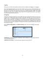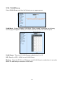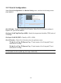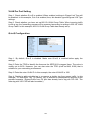
1
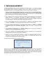
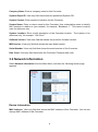
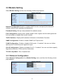
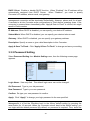
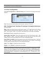
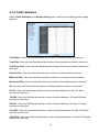
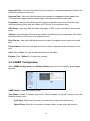
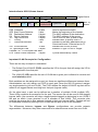
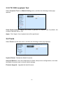
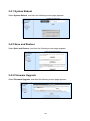
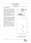
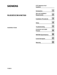
WAC-3112 SERIES 10/100/1000BASE-T to 1000BASE-X Managed Media Converter with Extended Operating Temperature WAC-2112 SERIES 10/100BASE-T to 100BASE-X Managed Media Converter with Extended Operating Temperature WPC-3112 SERIES 10/100/1000BASE-T to 1000BASE-X Managed Media Converter with Builtin PoE/PSE Feature and Extended Operating Temperature WPC-2112 SERIES 10/100BASE-TX to 100BASE-FX Managed Media Converter with Built-in PoE/PSE Feature Extended Operating Temperature Network Management User’s Manual Version 1.0 Trademarks CTS is a registered trademark of Connection Technology Systems Inc.. Contents subject to revision without prior notice. All other trademarks remain the property of their respective owners. Copyright Statement Copyright 2012 Connection Technology Systems Inc., All Rights Reserved. This publication may not be reproduced as a whole or in part, in any way whatsoever unless prior consent has been obtained from Connection Technology Systems Inc.. FCC Warning This equipment has been tested and found to comply with the limits for a Class-A digital device, pursuant to Part 15 of the FCC Rules. These limitations are designed to provide reasonable protection against harmful interference in a residential installation. This equipment generates, uses and can radiate radio frequency energy and, if the equipment is not installed and used in accordance with the instructions, it may cause harmful interference to radio communications. However, there is no guarantee that interference will not occur in a particular installation. If this equipment does cause harmful interference to radio or television reception, which can be determined by turning the equipment off and on, the user is encouraged to try to correct the interference by one or more of the following measures: Reorient or relocate the receiving antenna. Increase the separation between the equipment and receiver. Connect the equipment into an outlet on a circuit different from that to which the receiver is connected. Consult your local distributors or an experienced radio/TV technician for help. Shielded interface cables must be used in order to comply with emission limits. Changes or modifications to the equipment, which are not approved by the party responsible for compliance, could affect the user‟s authority to operate the equipment. Copyright © 2012 All Rights Reserved. Company has an on-going policy of upgrading its products and it may be possible that information in this document is not up-to-date. Please check with your local distributors for the latest information. No part of this document can be copied or reproduced in any form without written consent from the company. Trademarks: All trade names and trademarks are the properties of their respective companies. 2 Table of Contents 1. INTRODUCTION ............................................................................................................... 4 1.1 Connecting the Media Converter .................................................................................. 4 1.1.1 Cabling .................................................................................................................. 4 1.1.2 IP Addresses.......................................................................................................... 5 1.1.3 MIB for Network Management Systems ................................................................ 5 2. SNMP NETWORK MANAGEMENT .................................................................................. 6 3. WEB MANAGEMENT ....................................................................................................... 7 3.1 System Information ...................................................................................................... 8 3.2 Network Information ..................................................................................................... 9 3.3 Module Setting ........................................................................................................... 11 3.3.1 Network Configuration ......................................................................................... 11 3.3.2 Password Setting ................................................................................................. 12 3.3.3 Port Configuration ................................................................................................ 13 3.3.4 Traffic Statistics .................................................................................................... 14 3.3.5 SNMP Configuration ............................................................................................ 15 3.3.6 VLAN Configuration ............................................................................................. 16 3.3.6.1 VLAN Group .................................................................................................. 20 3.3.6.2 VLAN Per Port Setting................................................................................... 21 3.3.7 Q-in-Q Configuration ............................................................................................ 22 3.3.8 VLAN & Q-in-Q Application Examples ................................................................. 23 3.3.9 TS 1000 Loopback Test ....................................................................................... 27 3.4 Tools .......................................................................................................................... 27 3.4.1 System Reboot .................................................................................................... 28 3.4.2 Save and Restore ................................................................................................ 28 3.4.3 Firmware Upgrade ............................................................................................... 28 3 1. INTRODUCTION Thank you for purchasing the 10/100BASE-TX to 100BASE-FX or 10/100/1000BASE-T to 1000BASE-X Managed Media Converter with Extended Operating Temperature which is specifically designed to fulfill emerging deployment needs of fiber Ethernet networks. The Managed Media Converter has built-in management module that allows users to configure the device and monitor the operation status both locally and remotely through the network. This user‟s manual starts with basic introduction to the device and proper cable arrangement to connect your devices. For information about SNMP and Web Management, please refer to Section 2 and Section 3. 1.1 Connecting the Media Converter Before you can configure the Managed Media Converter, you must firstly connect your devices appropriately. It is very important that the proper cables with the correct pin arrangement are used when connecting the Managed Media Converter to other devices such as switches, hubs, workstations, etc.. Last but not least, IP address should be assigned correctly to your device according to your network environment plan without IP address conflicts within operating networks. 1.1.1 Cabling 1000Base-X / 100Base-FX SFP Port The small form-factor pluggable (SFP) is a compact optical transceiver used in optical data communication applications. It interfaces with a network device mother board (for a switch, router or similar device) to a fiber optic or unshielded twisted pair networking cable. It is a popular industry format supported by several fiber optic component vendors. SFP transceivers are available with a variety of different transmitter and receiver types, allowing users to select the appropriate transceiver for each link to provide the required optical reach over the available optical fiber type. SFP transceivers are also available with a "copper" cable interface, allowing a host device designed primarily for optical fiber communications to also communicate over unshielded twisted pair networking cable. SFP slot for 3.3V mini GBIC module supports hot swappable SFP fiber transceiver. Before connecting other switches, workstation or media converter, make sure both sides of the SFP transfer are with the same media type, for example, 1000Base-SX to 1000Base-SX, 1000Bas-LX to 1000Base-LX. In addition to that, check if the fiber-optic cable type matches the SFP transfer model. To connect to 1000Base-SX transceiver, use the multi-mode fiber cable with male duplex LC connector type for one side. To connect to 1000Base-LX transfer, use the single-mode fiber cable with male duplex LC connector type for one side. 4 10/100/1000Base-T RJ-45 Auto-MDI/MDIX Port The 10/100/1000Base-T RJ-45 Auto-MDI/MDIX port is located on the front panel of the Managed Media Converter. This RJ-45 port allows users to connect their traditional copperbased Ethernet/Fast Ethernet devices to the network and support auto-negotiation and MDI/MDIX auto-crossover. In other words, either crossover or straight through CAT-5E UTP or STP cable may be used. 1.1.2 IP Addresses IP addresses have the format n.n.n.n, (The default factory setting is 192.168.0.1). IP addresses consist of two parts: The first part (for example 168.168.n.n) refers to the network address that identifies the network where the device resides. Network addresses are assigned by three allocation organizations. Depending on your location, each allocation organization assigns a globally unique network number to each network that wishes to connect to the Internet. The second part (for example n.n.8.100) identifies the device within the network. Assigning unique device numbers is your responsibility. If you are unsure of the IP addresses allocated to you, consult with the allocation organization where your IP addresses were obtained. Remember that each device on a network must have a unique address. If you want to connect to the outside, you must change all the arbitrary IP addresses to comply with those you have been allocated by the allocation organization. If you do not do this, your outside communications will not be performed. A subnet mask is a filtering system for IP addresses. It allows you to further subdivide your network. You must use the proper subnet mask for proper operation of a network with subnets defined. 1.1.3 MIB for Network Management Systems Private MIB (Management Information Bases) is used to manage the Media Converter through the SNMP-based network management system. You must install the private MIB into your SNMP-based network management system first. The MIB file is shipped together with the Managed Media Converter. The file name extension is “.mib”, allowing SNMP-based compiler to read and compile. 5 2. SNMP NETWORK MANAGEMENT The Simple Network Management Protocol (SNMP) is an application-layer protocol that facilitates the exchange of management information between network devices. It is part of the TCP/IP protocol suite. SNMP enables network administrators to manage network performance, find and solve network problems, and plan for network growth. SNMP consists of the following key components: Managed Device is a network node that contains SNMP agent. Managed devices collect and store management information and make this information available to NMS using SNMP. Managed devices can be switches, hub, etc.. MIB (Management Information Base) defines the complete manageable entries of the managed device. These MIB entries can be either read-only or read-write. For example, the System Version is read-only variable. The Port State Enable or Disable is a read-write variable and a network administrator can not only read but also set its value remotely. SNMP Agent is a management module resides in the managed device that responds to the SNMP Manager request. SNMP Manager/NMS executes applications that monitor and control managed devices. NMS provides the bulk of the processing and memory resources required for the complete network management. SNMP Manager often composed by desktop computer/work station and software program such like HP OpenView. Totally, 4 types of operations are used between SNMP Agent & Manager to change the MIB information. These 4 operations all use the UDP/IP protocol to exchange packets. GET: This command is used by SNMP Manager to monitor managed devices. The SNMP Manager examines different variables that are maintained by managed devices. GET Next: This command provides traversal operation and is used by the SNMP Manager to sequentially gather information in variable tables, such as a routing table. SET: This command is used by an SNMP Manager to control managed devices. The NMS changes the values of variables stored within managed devices. Trap: Trap is used by the managed device to report asynchronously a specified event to the SNMP Manager. When certain types of events occur, a managed device will send a trap to alert the SNMP Manager. The system built-in management module also supports SNMP management. Users must install the MIB file before using the SNMP based network management system. The MIB file is on a disc or diskette that accompanies the system. The file name extension is “.mib”, allowing SNMP based compiler to read and compile. Please refer to the appropriate documentation for instructions on installing the system private MIB. 6 3. WEB MANAGEMENT The Managed Media Converter can be managed via a Web browser. If you want to manage the Managed Media Converter remotely, follow these steps to access the built-in management module of this Managed Media Converter and set up the IP address: 1. When you use the Managed Media Converter for the first time or set the Managed Media Converter back to factory default setting, firstly connect one end of RJ-45 LAN cable to the RJ-45 port of the Managed Media Converter (as the temporary RJ-45 Management port) and the other end to your computer‟s RJ-45 port. 2. Then, make sure your computer is set to the same IP subnet address as the Managed Media Converter. For example, the default IP address of this Media Converter is 192.168.0.1. Your computer‟s IP address must be set to 192.168.0.X (where X denotes a number between 2 and 254) and subset mask to 255.255.255.0. 3. Run a Web browser and then use the default IP address of the Managed Media Converter “192.168.0.1” to access the login window which is shown below. 4. Enter the username and password. The default login username is “admin” and without a password (leave the password field blank). Then, click “Login” to reach the Main Menu. 5. Select Network Configuration from Module Setting menu to set up your desired IP address to reach this Managed Media Converter. 6. Once the IP address of this Managed Media Converter is specified, you can access the Managed Media Converter with the new IP address. 7. When you use the specified IP address to access the Managed Media Converter, remember to connect the other end of RJ-45 cable to an Ethernet port and set your computer‟s IP address back to original settings. A Login window looks like the one shown below: When you use the Managed Media Converter for the first time or set it back to the factory default settings, enter the login username “admin” and press Login. (By default, no password is required. Thus, leave the password field blank.) After a successful login, you will be directed to the Main Menu screen as shown below. Each menu function in the Web Management will be described in the following separate sections. 7 NOTE: The login username is set to “admin” permanently and can not be changed. However, the default login password can be changed to the desired one in Password Setting under the Module Setting menu. It is strongly recommended that the default password is changed to the one that is suitable for your networking environment for security reasons. System Information: Name the Converter, specify the system name and location and check the current version information. Network Information: Display device information, port status, and SFP status. Module Setting: Configure DHCP, Port, VLAN, Q-in-Q function and run loopback test. Tools: Restart the Converter, save configurations, restore backup configurations, and upgrade the latest firmware. NOTE: WPC-3112, WPC-2112, WAC-3112 and WAC-2112 have the same web management interface. This User’s Manual only uses WPC-3112 as an example in instruction descriptions. 3.1 System Information Select System Information from the Main Menu, and then the following screen appears. 8 Company Name: Enter a company name for this Converter. System Object ID: View-only field that shows the predefined System OID. System Contact: Enter contact information for this Converter. System Name: Enter a unique name for this Converter. Use a descriptive name to identify the Converter in relation to your network, for example, “Backbone 1”. This name is mainly used for reference only. System Location: Enter a brief description of the Converter location. The location is for reference only, for example, “13th Floor”. Software Version: View-only field that shows the product‟s firmware version. M/B Version: View-only field that shows the main board version. Serial Number: View-only field that shows the serial number of this Converter. Date Code: View-only field that shows the Converter Firmware date code. 3.2 Network Information Select Network Information from the Main Menu, and then the following screen page appears. Device Information MAC Address: View-only field that shows the MAC address of this Converter. You can not change MAC address of this Converter. 9 IP Address: View-only field that shows the IP address of this Converter. You can change the IP address to the desired one in Network Configuration under the Module Setting Menu. Gateway: View-only field that shows the Gateway address of this Converter. You can change the Gateway address to the desired one in Network Configuration under the Module Setting Menu. Subnet Mask: View-only field that shows the Subnet Mask of this Converter. You can change the Subnet Mask to the desired one in Network Configuration under the Module Setting Menu. Description: View-only field that shows the description you indicate. You can change the description in Network Configuration under the Module Setting Menu. Port Status Signal detect (SD): View-only field that shows whether the signal TP and FX is detected or not. Link status: View-only field that shows the link status of TP and FX. If the link is up, “On” will be shown. Speed: View-only field that shows the current speed of TP and FX. Duplex mode: View-only field that shows whether TP and FX are in full-duplex or halfduplex mode. Flow control: View-only field that shows whether TP and FX‟s flow control function is enabled or not. Auto negotiation: View-only field that shows whether TP and FX‟s auto negotiation function is enabled or not. SFP Status Temperature: View-only field that shows the slide-in SFP module operation temperature. Voltage (V): View-only field that shows the slide-in SFP module operation voltage. TX Power (dbm): View-only field that shows the slide-in SFP module optical Transmission power. RX Power (dbm): View-only field that shows the slide-in SFP module optical Receiver power. 10 3.3 Module Setting Select Module Setting and then the following screen page appears. Network Configuration: Enable or disable DHCP function and specify the desired IP address, subnet mask, gateway and description. Password Setting: Set up a new password for website access. Port Configuration: Specify ports‟ speed, duplex mode, ingress rate limit and egress rate limit and enable or disable flow control function. Traffic Statistics: Display traffic statistics information of this Media Converter. SNMP Configuration: Enable or disable SNMP and Trap function. VLAN Configuration: Enable or disable VLAN mode. If “enabled”, the user can further specify ports‟ VLAN Group and egress link type. Q-in-Q Configuration: Enable or disable Q-in-Q. If “enabled”, the user can further specify tag protocol identifier (TPID) and Q-in-Q direction. TS 1000 Loop Back: Run a loopback test. 3.3.1 Network Configuration Select Network Configuration from Module Setting menu, and then the following screen page appears. 11 DHCP Client: Enable or disable DHCP function. When “Enabled”, the IP address will be automatically assigned from DHCP Server. When “Disabled”, you need to specify Converter‟s IP address, subnet mask, and gateway. NOTE: When DHCP is enabled and “Apply & Save to Flash” is clicked, the web management connection will be terminated immediately. However, please wait for at least 8 seconds to let the Converter write configurations to Flash before powering down. If the converter is powered down immediately after “Apply& Save to Flash” is clicked, this might result in Flash crashes. IP Address: When DHCP is disabled, you can specify your desired IP address. Subnet Mask: When DHCP is disabled, you can specify your desired subnet mask. Gateway: When DHCP is disabled, you can specify your gateway address. Description: Specify a name or give a brief description to this Converter. Apply & Save To Flash: Click “Apply & Save To Flash” to change and save your setting. 3.3.2 Password Setting Select Password Setting from Module Setting menu, then the following screen page appears. Login Name: View-only filed. This default login name can not be changed. Old Password: Type in your old password. New Password: Type in your new password. Confirm: Re-type your new password to confirm. Apply: Click “Apply” to change your login password to the one specified. NOTE: If you forget the login password, the only way to gain access to the Web Management is to set the Converter back to the factory default setting by pressing the reset button for 10 seconds. When the Converter returns back to the default setting, you can login with the default password (By default, no password is required. Thus, leave the 12 field empty and then press Login.) See Page 8 for login procedure when setting the Media Converter back to the factory default setting. 3.3.3 Port Configuration Select Port Configuration from Module Setting menu, and then the following screen page appears. Port: There are two kinds of ports in this Converter, which are TP and FX. Link: This shows the current link status of TP and FX port. For example, when the link is down, it will display “Down”. When the link is connected, it will display the current speed and mode status. Mode: Select the desired speed or/and duplex mode. For TP port, there are six options available from the pull-down menu, these are “Auto Speed”, “1000 Full”, “100 Full”, “100 Half”, “10 Full”, and “ 10 Half”. For FX port, “Auto mode” and “Force mode” are available. Flow Control: Enable or disable flow control function. Ingress Rate Limit (kbps): Select the ingress rate limit from the pull-down menu. “Not Limit” indicates “0” kbps. If you want to specify your own rate limit, you can select “User Setting” and then state your desired rate limit in the corresponding space. Egress Rate Limit (kbps): Select the egress rate limit from the pull-down menu. “Not Limit” indicates “0” kbps. If you want to specify your own rate limit, you can select “User Setting” and then state your desired rate limit in the corresponding space. Apply: Click “Apply” to change and save the setting. Refresh: Click “Refresh” to refresh the current status. NOTE: When DIP 8 (on the Rear Panel of the Managed Media Converter) is set to “ON” (which means that Mode and Flow Control will be set according to configurations in DIP Switch), you can not change TP and FX’s Mode and Flow Control in Web Management. On the other hand, when DIP 8 is set to “OFF” (which means that Mode and Flow Control will be set according to configurations in Web Management), DIP 1~5 setting (set to “ON”) will be ignored. 13 3.3.4 Traffic Statistics Select Traffic Statistics from Module Setting menu, and then the following screen page appears. Total Bytes: View-only field that shows the number of received frames on each port. Total Pkts: View-only field that shows the number of total packets received on each port. Total Error Pkts: View-only filed that shows the number of total error packets received on each port. Unicast Pkts: View-only field that shows the number of unicast packets received. Multicast Pkts: View-only field that shows the number of multicast packets received. Broadcast Pkts: View-only field that shows the number of broadcast packets received. 64: View-only field that shows the number of 64byte packets received on each port. 65-127: View-only field that shows the number of packets between 65 and 127 bytes received on each port. 128-288: View-only field that shows the number of packets between 128 and 288 bytes received on each port. 256-511: View-only field that shows the number of packets between 256 and 511 bytes received on each port. 512-1023: View-only field that shows the number of packets between 512 and 1023 bytes received on each port. 1024-1518: View-only field that shows the number of packets between 1024 and 1518 bytes received on each port. 14 Undersize Pkts: View-only field that shows the number of undersized packets (smaller than 64 bytes) received on each port. Oversize Pkts: View-only field that shows the number of untagged packets greater than 1518 bytes and tagged packets greater than 1522 bytes received on each port. Fragments: View-only field that show the number of packets that are less than 64 bytes (excluding framing bits) and have either an FCS error or an alignment error. CRC Errors: View-only field that show messages of CRC (cyclic redundancy check) data errors. Jabbers: View-only field that shows the number of packets that are longer than 1522 bytes and have either an FCS error or an alignment error. Drop Events: View-only field that shows the number of dropped events received on each port. Pause Frames: View-only field that shows the number of pause frames received on each port. Clear: Click “Clear” to clear all statistics shown on the table. Refresh: Click “Refresh” to refresh the counter. 3.3.5 SNMP Configuration Select SNMP Configuration from Module Setting menu, then the following screen page appears. SNMP Ability: Enable or disable SNMP. Trap Mode: Enable or disable trap mode. When enabled, a trap will be sent when the following events occur. Cold Start: When the Converter runs cold start, a trap notice will be sent. Power Down: When the Converter is powered down, a trap notice will be sent. 15 Link Up: When TP or FX link is established, a trap notice will be sent. Link Down: When TP or FX link is disconnected, a trap notice will be sent. SNMP Trap IP Address: Specify the IP address to which the trap will be sent. Read Community: Specify a username up to 31 characters for SNMP login. This allows users to read only. Read_Write Community: Specify a username up to 31 characters for SNMP login. This allows users to read and make some setting changes. Apply: Click “Apply”, and then configurations and changes will be saved. 3.3.6 VLAN Configuration A Virtual Local Area Network (VLAN) is a network topology configured according to a logical scheme rather than the physical layout. VLAN can be used to combine any collections of LAN segments into a group that appears as a single LAN. VLAN also logically segments the network into different broadcast domains. All broadcast, multicast, and unknown packets entering the Converter on a particular VLAN will only be forwarded to the stations or ports that are members of that VLAN. VLAN can enhance performance by conserving bandwidth and improve security by limiting traffic to specific domains. A VLAN is a collection of end nodes grouped by logics instead of physical locations. End nodes that frequently communicate with each other are assigned to the same VLAN, no matter where they are physically located on the network. Another benefit of VLAN is that you can change the network topology without physically moving stations or changing cable connections. Stations can be „moved‟ to another VLAN and thus communicate with its members and share its resources, simply by changing the port VLAN settings from one VLAN to another. This allows VLAN to accommodate network moves, changes and additions with the greatest flexibility. 802.1Q VLAN Concept Port-Based VLAN is simple to implement and use, but it cannot be deployed across converters VLAN. The 802.1Q protocol was developed in order to provide the solution. By tagging VLAN membership information to Ethernet frames, the IEEE 802.1Q can help network administrators break large networks into smaller segments so that broadcast and multicast traffic will not occupy too much available bandwidth as well as provide a higher level security between segments of internal networks. 16 Introduction to 802.1Q frame format: Preamble SFD DA SA Type/LEN Preamble SFD DA SA TAG Type/LEN TCI/P/C/VID PRE SFD DA SA TCI P C Preamble Start Frame Delimiter Destination Address Source Address Tag Control Info Priority Canonical Indicator 62 bits 2 bits 6 bytes 6 bytes 2 bytes 3 bits 1 bit PAYLOAD FCS Original frame PAYLOAD FCS 802.1q frame Used to synchronize traffic Marks the beginning of the header The MAC address of the destination The MAC address of the source Set to 8100 for 802.1p and Q tags Indicates 802.1p priority level 0-7 Indicates if the MAC addresses are in Canonical format - Ethernet set to "0" Indicates the VLAN (0-4095) Ethernet II "type" or 802.3 "length" VID VLAN Identifier 12 bits T/L Type/Length Field 2 bytes Payload < or = 1500 bytes User data FCS Frame Check Sequence 4 bytes Cyclical Redundancy Check Important VLAN Concepts for Configuration There are two key concepts to understand. - The Default Port VLAN ID (PVID) specifies the VID to the port that will assign the VID to untagged traffic from that port. - The VLAN ID (VID) specifies the set of VLAN that a given port is allowed to receive and send labeled packets. Both variables can be assigned to a port, but there are significant differences between them. Administrators can only assign one PVID to each port (since the 802.1Q protocol assigns any single packet to just one VLAN). The PVID defines the default VLAN ID tag that will be added to un-tagged frames receiving from that port (ingress traffic). On the other hand, a port can be defined as a member of multiple VLAN (multiple VID). These VIDs constitute an access list for the port. The access list can be used to filter tagged ingress traffic (the converter will drop a tagged packet tagged as belonging in one VLAN if the port on which it was received is not a member of that VLAN). The converter also consults the access list to filter packets it sends to that port (egress traffic). Packets will not be forwarded unless they belong to the VLANs that the port is one of the members. The differences between Ingress and Egress configurations can provide network segmentation. Moreover, they allow resources to be shared across more than one VLAN. 17 Important VLAN Definitions Ingress The point at which a frame is received on a converter and the decisions must be made. The converter examines the VID (if present) in the received frames header and decides whether or not and where to forward the frame. If the received frame is untagged, the converter will tag the frame with the PVID for the port on which it was received. It will then use traditional Ethernet bridging algorithms to determine the port to which the packet should be forwarded. Next, it checks to see if each destination port is on the same VLAN as the PVID and thus can transmit the frame. If the destination port is a member of the VLAN used by the ingress port, the frame will be forwarded. If the received frame is tagged with VLAN information, the converter checks its address table to see whether the destination port is a member of the same VLAN. Assuming both ports are members of the tagged VLAN, the frame will be forwarded. Ingress Filtering The process of checking an incoming frame and comparing its VID with the ingress port VLAN membership is known as Ingress Filtering. On the Media Converter, it can be either enabled or disabled. 1. When an untagged frame is received, the ingress port PVID will be applied to the frame. 2. When a tagged frame is received, the VID in the frame tag is used. When Ingress Filtering is “Enabled”, the Media Converter will first determine, 1. If the ingress port itself is a member of the frame VLAN, it will receive the frame. 2. If the ingress port is not a member of the frame VLAN, the frame will be dropped. 3. If it is a member of that VLAN, the Media Converter then checks its address table to see whether the destination port is a member of the same VLAN. Assuming both ports are members of that VLAN, the frame will be forwarded. Administrators should make sure that each port‟s PVID is set up; otherwise, incoming frames may be dropped if Ingress Filtering is enabled. On the other hand, when Ingress Filtering is disabled, the Media Converter will not compare the incoming frame VID with the ingress port VLAN membership. It will only check its address table to see whether the destination VLAN exists. 1. 2. 3. If the VLAN is unknown, it will be broadcasted. If the VLAN and the destination MAC address are known, the frame will be forwarded. If the VLAN is known and the destination MAC address is unknown, the frame will be flooded to all ports in the VLAN. 18 Tagging Every port on an 802.1Q compliant converter can be configured as tagging or un-tagging. Ports with taggings Enable will put the VID number, priority and other VLAN information into the header of all packets that flow into and out of it. If a packet has been tagged previously, the port will not alter the packet and keep the VLAN information intact. The VLAN information in the tag can then be used by other 802.1Q compliant devices on the network to make packet forwarding decisions. Un-tagging Ports with un-taggings Enable will strip the 802.1Q tag from all packets that flow into and out of those ports. If the packet does not have an 802.1Q VLAN tag, the port will not alter the packet. Thus, all packets received by and forwarded by an un-tagging port will have no 802.1Q VLAN information. Un-tagging is used to send packets from an 802.1Q-compliant network device to a non-compliant network device. Simply put, un-tagging means that once you set up the port as “U” (untagged), all egress packets (in the same VLAN group) from the port will have no tags. Select VLAN Configuration from Module Setting menu, then the following screen page appears. VLAN Group: Enable or disable VLAN Mode. When enabled, you can further indicate a VID to the selected ports. VLAN Per Port Setting: Set up each port‟s egress link type and VID. 19 3.3.6.1 VLAN Group Select VLAN Group, and then the following screen page appears. VLAN Mode: Enable or disable VLAN Mode. When “enable” is selected, the following screen page will appear to allow you to further indicate a VID to the selected ports. VLAN Group: There are 16 VLAN Groups available from 0 to 15. VID: Specify a VID (1~4094) to each VLAN Group. Member: Check the TP, FX, or CPU box in each VLAN Group to enable them to carry the same VID and belong to the same VLAN Group. 20 3.3.6.2 VLAN Per Port Setting Select VLAN Per Port Setting, and then the following screen page appears. Port: This column indicates the ports available; these are TP, FX, and CPU. Egress Link Type: Select the needed egress link type from the pull-down menu. Please note that when Q-in-Q is enabled, settings in Egress Link Type will be disabled. Replace Tag: This will change the VID of packets to the specified one. Remove Tag: This will remove packets‟ VID. Add Tag: This will add the specified VID to packets. Don’t Touch Tag: This will keep packets intact. Port VLAN Entry: Select each port‟s corresponding VID from the pull-down menu. When you specify “Add Tag” as Egress Link Type, the VID selected will be added to the packet. Ingress Filter: To enable or disable ingress filter. See above for the introduction to and uses of Ingress Filtering. 21 3.3.7 Q-in-Q Configuration Select Q-in-Q Configuration from Module Setting menu, and then the following screen page appears. Q in Q Enable: Enable or disable Q-in-Q function. When Q-in-Q is enabled, settings in Egress Link Type will be disabled. Out Layer VLAN Tag EtherType (HEX): Specify the tag protocol identifier (TPID) value of VLAN tags. Out Layer VLAN VID (DEC): Specify a VID (1~4094). Q in Q Direction: Select Q-in-Q direction from the pull-down menu. TP Add Q in Q Tag, FX Remove Tag: TP port inserts a Q-in-Q tag and FX port removes a Q-in-Q tag. FX Add Q in Q Tag, TP Remove Tag: FX port inserts a Q-in-Q tag and TP port removes a Q-in-Q tag. NOTE: When traffic is untagged and Q-in-Q is enabled with proper settings, the traffic will be forwarded out with only one tag (Out Layer VLAN VID). 22 3.3.8 VLAN & Q-in-Q Application Examples In this section, two example figures are provided to explain the VLAN and Q-in-Q configurations. Application Example 1: As illustrated below, TP port is connected to the customer device that has incoming traffic with VLAN 100. If you want traffic forwarded out FX port to be added with a double tag 1000, then follow the steps below to accomplish the process. VLAN Group Step 1. By default, VLAN mode is disabled. Make sure you enable VLAN mode before carrying on the following steps. Step 2. Specify VID 100 and 1000 in VLAN Group 1 and 2 respectively. Select TP, FX, and CPU as member ports in VLAN Group 1 and 2 (When CPU is selected as a member, the VLAN becomes management VLAN.). Step 3. Click “Apply” to make settings effective. 23 VLAN Per Port Setting Step 1. Check whether Q-in-Q is enabled. When enabled, settings in Egress Link Type will be disabled. In this example, Q-in-Q is enabled; thus, this decision ignores Egress Link Type settings. Step 2. Check whether you have set up 802.1Q VLAN Group Table. When incoming traffic is with a tag, the forwarding process will be executed according to settings in 802.1Q VLAN Group Table. In this example, 802.1Q VLAN Group Table has already set up. Q-in-Q Configuration Step 1. By default, Q-in-Q is disabled. Make sure Q-in-Q is enabled before apply the settings. Step 2. Enter the TPID to identify the frame as the IEEE 802.1q-tagged frame. The value is usually set to 8100. However, you can also enter the TPID (such as 88A8, 9100) that is suitable for your networking environment. Step 3. Enter the outer VLAN ID. In this example, the outer VLAN ID is 1000. Step 4. Decide to add a double tag to or remove a double tag from egress traffic. In this example, “FX Add QinQ Tag, TP remove Tag” is selected to accomplish the process of the provided scenario. (Egress traffic from FX port has already had a tag with VID 100. The other tag with VID 1000 will also be added.) 24 Application Example 2: In this backbone scenario, suppose two stand-alone Converters are used to extend the distance up to 80KM (depending on the models used). On the left-hand side, PC1 is the management PC that can manage the “Converter 1” remotely via the TP port. PC2 and PC4 are in the same VLAN 110 and should be able to communicate with each other. PC3 and PC5 are also in the same VLAN 220 and should be able to communicate with each other. To allow management and data traffic to flow to and from the Converter in this scenario, the following steps to configure “Converter 1” are suggested. 802.1Q VLAN Group Step 1. By default, VLAN mode is disabled. Make sure you enable VLAN mode before carrying on the following steps. Step 2. Specify VID 110, 220, 330 in VLAN Group 0, 1, 2 respectively. Select TP and FX in VLAN Group 0 and 1 and select TP and CPU in VLAN Group 2 (When CPU is selected as a member, the VLAN becomes management VLAN.). Step 3. Click “Apply” to make settings effective. 25 802.1Q VLAN Per Port Setting Step 1. Set TP port‟s Egress Link Type to “Add Tag” and select VLAN Group 2 (330). When Management PC1 sends out a frame, the Converter will remove VLAN tag 330 within a frame. To ensure the link will not be disconnected due to the lack of the appropriate tag, TP port‟s Egress traffic should be added a tag 330. Step 2. Set FX port‟s Egress Link Type to “Don‟t Touch Tag”. When PC2 wants to send a frame to PC4, the Converter will forward it out FX port directly based on settings in “802.1Q VLAN Group”. Step 3. Select VLAN Group 2 as CPU‟s Port VLAN Entry setting. 26 3.3.9 TS 1000 Loopback Test Select Loopback Test from Module Setting menu, and then the following screen page appears. Send Packet Number: Specify the number of packets for loopback test. By default, the number of packets sent is 100. Apply: Click “Apply”, then loopback test will be performed. 3.4 Tools Select Tools from the main menu, and then the following screen page appears. System Reboot: Restart the Media Converter. Save and Restore: Save all configurations to flash, load previous configurations, and reset the Media Converter back to factory default settings. Firmware Upgrade: Upgrade the latest firmware. 27 3.4.1 System Reboot Select System Reboot, and then the following screen page appears. 3.4.2 Save and Restore Select Save and Restore, and then the following screen page appears. 3.4.3 Firmware Upgrade Select Firmware Upgrade, and then the following screen page appears. 28 This page is intentionally left blank. Manual Version 0.91 Modification The initial version Firmware Version Date 2011/08 NOTE: This User’s Manual is written or revised according to the officially-released Firmware version. The content of this Manual is subject to change without prior notice. 29