1
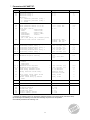
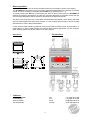
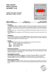
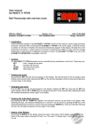
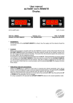
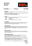
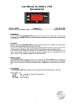
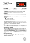
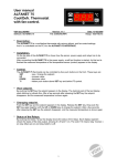
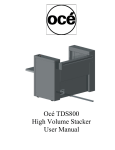
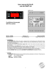
User manual ALFANET 57 (4-20mA) Pressostat with temperature read-out and controlling on the base of various cooling means. VDH doc. 060342 Software: ALFA 57/67/77 4-20 Version: v1.0 File: Do060342.WP8 Date: 01-02-2006 Range: -1,0/+99,9 BAR per 0,1BAR * Description. The ALFANET 57 is a pressostat which can control pressure as well as temperature (of various cooling means). It is adjustable through the ALFANET PC-INTERFACE on the PC (RS485-network). * Installation. On the connection diagram of the ALFANET 57 is shown how the sensor, power supply and relays have to be connected. A few seconds after connecting the ALFANET 57 to the power supply, the measured pressure of the pressure sensor appears in the display. * Control. The ALFANET 57 pressostat can be controlled by four pushbuttons on the front. These keys are: SET - view / change the setpoint. UP - increase value. DOWN - decrease value. MODE - relay status key. * Read-out and control on temperature. The ALFANET 57 pressostat normally controls under atmospheric pressure (no absolute pressure). If a cool means with parameter P08 is chosen, the controller can read-out and control the temperature with the help of P09. At this can be chosen to read-out the temperature per 0,1C or per 1C. To the indication that the temperature is been shown in stead of the pressure, the most right decimal point is burning with the text 'C'. By switching over the pressure read-out (controlling) to the temperature read-out (controlling) and opposite, the various parameters (marked with #) will be turned into another unit. By changing the parameters it is recommended to check if the parameters are standing good for the intended goal. * Viewing setpoint. By pushing the SET key the setpoint appears in the display. The decimal point of the most right display starts blinking to indicate that the setpoint is being read-out. A few seconds after releasing the SET key the set point disappears and the measured value is shown again. 1 * Changing setpoint. Push the SET key so the setpoint appears in the display. Release the SET key. Now push the SET key again together with the UP or DOWN keys to change the setpoint. A few seconds after releasing the keys the measured value is shown again. * Status of the relays. By pushing the MODE key, the display shows the status of the relays. Each display segment shows the status of the relay output, showing 0= off and 1=on. The code 110 means relay 1en relay 2 are on and relay 3 is off. * Setting internal parameters. Next to the adjustment of the setpoint, some internal settings are possible like differentials, sensor-adjustments, setpoint-range, cool means, read-out settings and alarm-settings. By pushing the DOWN key for more than 10 seconds, you enter the 'internal programming menu'. In the left display the upper and the lower segments are blinking. By pushing the UP and/or DOWN keys the required parameter can be selected (see parameter table). If the required parameter is selected, the value can be read-out by pushing the SET key. Pushing the UP and/or DOWN keys allows you to change the value of this parameter. If after 20 seconds no key is pushed, the ALFANET 57 changes to it's normal operation mode. * Sensor adjustment. The pressure-sensor can be adjusted by using the Offset pressure sensor (parameter 05). If the ALFANET 57 indicates e.g. 0,2 BAR too much, the Offset pressure sensor parameter has to be decreased with 0,2 BAR. * Error messages. In the display of the ALFANET 57 the following error messages can appear: LO - Minimum alarm. Solution EE: HI - Maximum alarm. - Reprogram the settings. EE - Settings are lost. * Technical data. Type Range Supply Relay Communication Control Front Pressure sensor Dimensions Panel cut-out Accuracy : ALFANET 57 Pressostat (with cool means) : -1,0/+99,0 BAR, readout per 0,1 BAR (At selected cool means it also possible to readout the according temperature to the measured pressure, with a maximum range of -60,0C ....+60,0C.) : 230 Vac (or 24Vdc or 12Vdc) : The three relays have one common; Ry-1 (out-1) SPST (NO) 250V/8A (cos phi=1) Ry-2 (out-2) SPST (NO) 250V/8A (cos phi=1) Ry-3 (alarm) SPDT (NO,NC) 250V/8A (cos phi=1) : RS485-Network (A,B,Gnd: 3-wire shielded cable min. 0,5mm2) : Through pushbuttons on front. : Polycarbonate IP65 : PX25, PX75 or PX77 series (Supply 12Vdc, Signal input 4-20mA, 0V Gnd) Only for relative pressure sensors (Not for absolute pressure sensors). : 90 x 71 x 58mm (hwd) : 46 x 71mm (hw) at front mounting : ± 0,5 % of range. - Provided with memory protection during power failure. - Connection with screw-terminals upper site and bottom site . - Special version on request available. 2 * Parameters ALFANET 57. Par. Description Parameter Range 01 02 03 Function relay 1 Function relay 2 Function relay 3 Whereby: 1 = Increase pressure (temp.) 2 = Decrease pressure (temp.) 3 = Alarm 1..3 1..3 1..3 05 06 07 08 Offset pressure sensor Rate pressure sensor at 0V in Rate pressure sensor at 5V in Cool mean choice: 0=none 6=R407A(BP) 1=R22 7=R407C(DP) 2=R134A 8=R407C(BP) 3=R404A(DP) 9=R717 (NH3) 4=R404A(BP) 10=R507 5=R407A(DP) (DP = Dew point, BP = Bubble point) Read-out and control selection -15.0..+15.0 Bar -1.0..+99.0 Bar -1.0..+99.0 Bar 0..10 0.0 -1.0 9.0 0 0=Pressure (Bar) 1=Temp. Per 0,1°C 2=Temp. Per 1°C 0 Switching Switching Switching Switching Switching Switching 0.1..15 Bar (°C) -15..+15 Bar (°C) 0.1..15 Bar (°C) -15..+15 Bar (°C) 0.1..15 Bar (°C) -15..+15 Bar (°C) 0.5 0 0.5 0 0.5 0 09 10 11 12 13 14 15 # # # # # # 20 # 21 # 30 31 # 32 # 33 34 35 36 37 differential offset relay differential offset relay differential offset relay relay 1 1 relay 2 2 relay 3 3 Minimum setpoint setting Maximum setpoint setting * * Alarm mode: 0=None 1=Absolute 2=Relative Minimum alarm setpoint Maximum alarm setpoint Time delay minimum alarm Time delay maximum alarm Relay function alarm relay -1.0..99.0 Bar (°C) -1.0..99.0 Bar (°C) 0..2 * * Auto reset alarm after alarm recovering (0=hold) Reset alarm relay by manual reset -99..+99 Bar (°C) -99..+99 Bar (°C) 0..99 Minutes 0..99 Minutes 0=Watch alarm 1=Control alarm 0=No, 1=Yes Default 1 2 3 -1.0 9.0 1 -1.0 9.0 0 0 0 0 0=No, 1=Yes 0 40 Startup delay after power failure 0..99 Minutes 0 52 Time correction -99..+99 Min/Year 0 90 95 96 97 98 99 Network number Software version Production year Production week Serial number (x1000) Serial number (units) 1..255 0..255 00..99 1..52 0..255 0..999 1 - *) Changes by switching Bar/C or changes by selecting another cool means (check parameter value). #) Unit changes at switching over read-out/controlling on pressure or temperature. Check these parameters at switching over. 3 * Alarm operation. As a failure or alarm occurs the buzzer activates and an error message is shown in the display. The ALFANET 57 remembers its error message (parameter P36 default on 0), although it is already solved. The error message is resettable with the SET key (if parameter P37 = 1). As if after pressing the SET key (=reset alarm) the alarm is still not solved than the ALFANET 57 displays the pressure (temperature) and the error message alternated. Is the alarm solved, then the error message disappears and the pressure (temperature) is displayed normally. The alarm relay can be set on the control alarm with parameter P35 (default = watch alarm), which will say if the alarm appears the alarm relay activates. In case of watch alarm the alarm relay is normally activated and in case of alarm it deactivates. Further a alarm mode selection (parameter P35) can be made as follows; None, absolute alarm or relative alarm. In case of relative alarm the minimum alarm setpoint (parameter 31) and maximum alarm setpoint (parameter 32) are relative to the main setpoint. * * * Connections. Dimensions. Address. VDH Products BV Produktieweg 1 9301 ZS Roden The Netherlands Tel: Fax: Email: Internet: 4 +31 (0)50 30 28 900 +31 (0)50 30 28 980 [email protected] www.vdhproducts.nl