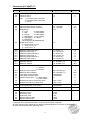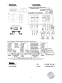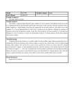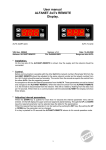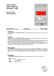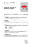
1
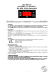
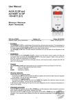
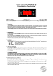
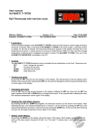
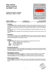
User manual ALFA(NET) 77 BAR (4-20mA) Pressostat with temperature Read out and control based on several refrigerants. VDH doc. 053105 Software: ALFA(NET) 57/67/77 4-20 Version: v1.1 File: Do053105.wpd Date: 24-03-2010 Range: -1,0/+99,9 BAR per 0,1 BAR * Description. The ALFA(NET) 77 is a Pressostat with three relay functions and the possibility to control on pressure or on temperature from the several refrigerants. The ALFANET 77 has a RS 485 network connection so it can be read out control and adjusted on the PC when you connect it to our ALFANET PCINTERFACE. * Installation. On the connection diagram is shown how to connect the pressure sensor, power supply and relays. As soon as you connect the ALFA(NET) 77 to the power supply the self test will be started automatically. After this test the measured pressure or temperature will appear in the display. * Control. The ALFA(NET) 77 Pressostat can be controlled by four push buttons on the front: SET - view / change the setpoints. UP - increase a setpoint. DOWN - decrease a setpoint. BAR - hidden button under the BAR text. * Display and control on temperature The ALFA(NET) 77 Pressostat normally controls on atmospherical pressure (not absolute pressure). If you have selected a refrigerant (parameter P08) , the pressostat can also display and control on temperature, see settings of parameter P09. Where it’s possible to select reading per 0,1C or per 1C . To indicate temperature reading in stead of the pressure reading, the most right decimal point is on.(‘C’). When switching from pressure to temperature, some parameters (“#”) will be transferred in the other value. It is advisable to check all these parameters. * Viewing and changing the setpoint. By pressing the SET button the setpoint appears in the display. At the same time the most right decimal point will blink, indicating the setpoint is being displayed. Release the SET button. Now push the SET key again together with the UP or DOWN keys to change the setpoint. A few seconds after releasing the keys the measured temperature shows again in the display. * Status of the Relays. By pushing the hidden BAR key, the display shows the status of the relays. Each display segment shows the status of the relay output, showing 0=off and 1=on. The code 110 means relay 1(out.1) and 2 (out.2) are on and relay 3 (out.3) is off. * Pressure sensor adjustment. The pressure sensor can be adjusted by using the Offset pressure parameter 05. Indicates the Sensor e.g. 0,2 BAR to much, than the Sensor Offset has to be decreased with 0,2 BAR. 1 * Error messages. In the display of the ALFANET 77 the following errors can appear: LO - Minimum alarm. HI - Maximum alarm. EE - Settings are lost. Solution EE: - Reprogramm the settings. * Alarm function. As a failure or alarm occurs an error message is shown in the display and the buzzer (as mounted) will make noise. The ALFA(NET) 77 remembers it’s error message, although it is already solved (as parameter P36 is default value ‘0'). The error message is resettable with the SET key (only when parameter P37 is set on 1 ). If after pressing the SET key (=Alarm reset) and the alarm is still not solved, the ALFA(NET) 77 displays the pressure (temperature) and the error code alternated. Is the alarm solved, the error message disappears and the actual pressure (temperature) is displayed again. Through parameter 35 the alarm relay function can be changed from (default on watch alarm) to control alarm. At control alarm the relay will be activated when an alarm occurs, at watch alarm the relay is normally active and in case of alarm the relay falls off (also in case of power failure). Through parameter P30 you can select the type of alarm: none, absolute or relative alarm. At the function relative alarm, the minimum and maximum alarm settings will be taken relative from the control setpoint. * Technical details. Type Range Supply Readout Relays Communication Control Front Pressure sensor Dimensions Panel cutout Accuracy : ALFA(NET) 77 Pressostat : -1,0/+99,9 BAR, readout per 0,1 BAR ( As a refrigerant is chosen the temperature can also be displayed, Within a range of -60,0 until +60,0C.) : 12 Vac/16,5Vdc (-5/+10%) : 3-digit 7-segments display : The three relays have one common; Ry-1 Out.1 SPST (NO) 250V/8A (cos =1) Ry-2 Out.2 SPST (NO) 250V/8A (cos =1) Ry-3 Out.3 (Alarm) SPDT (NO,NC) 250V/8A (cos =1) : RS 485 (2x Twisted-pair shielded cable min. 0,5mm2) : Thru push buttons on the front. : Polycarbonate IP65 : PX25, PX75, PX77 (Supply 12Vdc, Signal input 4-20mA). Only relative pressure sensors (Not for absolute pressure sensors) Pressure sensor who need a higher voltage supply than 12Vdc, use external supply : 35 x 77 x 71,5mm (hwd) : 29 x 70mm (hw) : ± 0,5 % of the range - Provided with memory protection during power failure. - Connection with screw terminals at the back side. - Special versions on request available. * Setting internal parameters. Next to the adjustment of the setpoint, internal settings can be made like differential, sensor-offset, setpoint range, refrigerants, read out settings, alarm settings and the functions of the thermostat. Push the DOWN key for more than 10 seconds, to enter the 'Internal Programming Menu'. In the left display the upper- and lower-segment are blinking. Over the UP and DOWN keys the required parameter can be selected (see the table for the parameters). If the required parameter is selected, the value can be read-out by pushing the SET key. Pushing the UP or DOWN key to change the value of this parameter. If after 20 seconds no key is pushed, the ALFA(NET) 77 changes to the normal operation mode. 2 * Parameters ALFA(NET) 77. Par. Description Parameter Range 01 02 03 Function relay 1 Function relay 2 Function relay 3 with: 1 = Pressure (temp.) increase 2 = Pressure (temp.) decrease 3 = Alarm 1..3 1..3 1..3 05 06 07 08 Offset pressure sensor Value pressure sensor at 4mA in Value pressure sensor at 20mA in Refrigerants: 0 = none 6 = R407A(BP) 1 = R22 7 = R407C(DP) 2 = R134A 8 = R407C(BP) 3 = R404A(DP) 9 = R717(NH3) 4 = R404A(BP) 10 = R507 5 = R407A(DP) (DP=Dewpoint, BP=Bubblepoint) Display and control 0 = Pressure Per 0,1 Bar 1 = Temp. Per 0,1 oC 2 = Temp. Per 1 oC -15.0..+15.0 Bar -1.0..+99.9 Bar -1.0..+99.9 Bar 0..10 10 # 11 # 12 # 13 # 14 # 15 # Switching differential relay 1 Switching offset relay 1 Switching differential relay 2 Switching offset relay 2 Switching differential relay 3 Switching offset relay 3 0.1..15 Bar (oC) -15..+15 Bar (oC) 0.1..15 Bar (oC) -15..+15 Bar (oC) 0.1..15 Bar (oC) -15..+15 Bar (oC) 0.5 0 0.5 0 0.5 0 20 # 21 # Minimum setpoint Maximum setpoint -1.0..99.9 Bar (oC) -1.0..99.9 Bar (°C) -1.0 99.9 09 30 0..2 * * 36 37 0 = None 1 = Absolute 2 = Relative Minimum alarm setpoint Maximum alarm setpoint Time delay minimum alarm Time delay maximum alarm Function alarm relay 0 = Watch alarm 1 = Control alarm Reset alarm relay at recovering alarm Reset alarm relay by manual reset 40 31 # 32 # 33 34 35 Alarm mode; 0..2 * * -99..+99.9 Bar (oC) -99..+99.9 Bar (oC) 0..99 Minutes 0..99 Minutes 0..1 Default 1 2 3 0.0 -1.0 99.9 0 0 1 -1.0 99.9 0 0 0 0=No, 1=Yes 0=No, 1=Yes 0 0 Control delay after power-failure 0..99 Minutes 0 52 Time correction -99..+99 Hours/Year 0 90 95 96 97 98 99 Network number (at ALFANET 77 only) Software version Production year Production week Serial number (x1000) Serial number (units) 1..255 0..255 00..99 1..52 0..255 0..999 1 - (at real time clock) *) Changes when switched from Bar/C of switching to another refrigerant. #) Value changes when switching from display (read-out)/Control on pressure or temperature. Check these parameters after switching over!! 3 * Dimensions. * Connections. * Adresse. VDH Products BV Produktieweg 1 9301 ZS Roden The Netherlands Tel: Fax: Email: Internet: 4 +31 (0)50 - 30 28 900 +31 (0)50 - 30 28 980 [email protected] www.vdhproducts.nl