1
Thermal Comfort for Passive dwellings via Optimum Roof
Architecture (RoofOpt)
M.S.R Perera
Department of Computing
Informatics Institute of Technology, Sri Lanka
B. Modasia
Department of Computing
Informatics Institute of Technology, Sri Lanka
ABSTRACT
The occurrence of hot discomfort during the
daytime is a serious problem for the citizens living in
tropical regions. This drove the citizens to look intently
on thermal comfort conditions. In tropical regions, the
most prominent component that affects thermal comfort
is the roof architecture as roofs are exposed to direct
solar radiation. Conversely, in the modern world the
houses are influenced by modern architecture where,
the designer only concentrates on the aesthetic side of
the dwelling. Therefore, to avoid thermal discomfort,
designers use their experience, knowledge to determine
a better dwelling structure through different passive
methodologies. But professionals very rarely realize
that the current passive techniques will result in a
satisfactory solution to the dweller.
This paper presents a framework that will
provide an intelligent artifact which will determine the
optimum roof architecture according to thermal
comfort conditions in a dwelling. The proposed system
consists of three layered architecture and consists of
five main components. Each major component is
further divided into sub modules. Data Extractor
(DE),User preference component (UPC),Case based
reasoner(CBR) ,Fuzzy decider (FD) component and
Two
dimensional
designer
components
(2DDesign).This software tool promotes the concept of
“Thermal Comfort”, a novel, easy to use, intelligent
can be used to obtain the optimum roof architecture,
insulation material and thickness in tropical climatic
conditions.
1.0 INTRODUCTION
Warm humid climatic conditions prevail in
many parts of the world. This climate is experienced
in populous regions in South and Central America,
South Asia, South- East Asia and Africa. In such
regions experiencing warm humid climate
conditions, hot discomfort is one of the major
problems in houses and buildings [1].
Generally, the tropical climatic countries
have a high population density. Most of these
countries still remain as developing countries. With
the economic development, the energy consumption
for thermal comfort is also rising.
However, in recent times, a new trend has
emerged in the housing sector due to the influence of
modern architecture. This adverse situation is further
deteriorated by adopting various features for houses
and buildings that would be more suitable for
temperate climates. Many designers in this region
have ignored the climate in their designs, primarily
because they are pre-occupied with fashionable
building forms. They have tried to separate the
building from nature rather than integrate it. Once
separated, indoor thermal comfort should be
achieved using air-conditioners, fans etc. These will
require considerable amount of energy for operation
resulting in high cost to the dweller and the country
as a whole. This is not a desirable situation for most
of these countries, which are still in the developing
stage. Therefore, it is an essential fact that when
designing dwellings, the designer should give due
consideration to comply with nature to achieve
thermal comfort by maximizing the natural sources.
Currently, architects/designers use their
experience to design the appropriate roof
architecture and insulation thickness/material for a
particular building. Mostly, a great effort is spent on
Deciding the optimum combination of the
roof parameters
Deciding
the
appropriate
insulation
thicknesses & materials for a particular
dwelling to achieve thermal comfort.
Because of the unstructured, heuristic nature of this
method, that is
There is no proper calculation formulae
available to determine the appropriate
insulation thicknesses based on climatic
factors.
1
There is no proper algorithm to determine
the thermal comfort for a combination of
roof parameters
Optimum roof architecture, appropriate thickness,
thermal performances, energy consumption and
budget cannot be scientifically determined.
Thus, comes a need for a better software tool,
to “design thermal comfort dwellings”. There have
been numerous attempts found to designing low energy
dwellings and thermal comfort dwellings. RESFEN
2.1 [2], Building Design Advisor [3], ASHRAE
Thermal Comfort Tool [4], DEROB-LTH [5] etc are
some of the commercial applications found in the
market today. Most of these concentrate on energy
consumption, low energy or thermal comfort
achieved to measure hypothetical human at a point
in space through mathematical calculations,
algorithms/ simulations etc. These applications are
specifically design to cater to the cold climates like
USA, Europe etc. In order to provide optimum
solution, reasoning the answer, provide alternative
solutions an intelligent tool has to be devised.
Continuous increase in computational power
has encouraged the development of software tools in
many different fields such as medical, automotive,
finance etc. During the research carried out, it was
revealed that the underlying concept has only been
confined as a theoretical fact. It has not been
practiced in real life scenarios in Sri Lanka. Dealing
with changing climatic conditions, managing
enormous amount of data and performing
mathematical calculations are impossible tasks to a
normal human being. As a result, lack of practical
exposure to the phenomenon “Thermal Comfort” is
minimal. In order to approach the architectural
community, an artifact should be devised to guide
the architects, designers, to achieve thermal comfort
in their architectural presentations and expose the
professionals to take up this phenomenon to the
architectural community. It is important to note that
there is no proper tool designed to decide on
optimum solutions, provide alternative solutions and
weigh the pros and cons of solutions offered in this
field of architecture.
2.0 PROBLEMS IN DESIGNING
OPTIMUM ROOF ARCHITECUTRE
AND DECIDING APPROPRIATE
THERMAL INSULATION
MATERIALS
In designing optimum roof architecture and
appropriate reflective/ resistive insulation materials for
a particular dwelling situated in a particular region or
zone [6] is a problematic issue in many facets. Many
problems associated in deigning can be overcome
successfully by incorporating complex expert
knowledge/ experience, experimental results and
importantly natural resources such as sunlight,
ventilation and humidity. Great emphasis was carried
out on acquiring proper and accurate expert knowledge
also their experimental results. Not only expert
information, climatic information was obtained in order
to analyze the thermal comfort values per region and to
obtain its comfort zones [6]. The research in gives and
account for the strengths and weaknesses of software
tools that have been practiced in the architectural
world.
In order to deal with expert knowledge,
climatic information and also to obtain optimum
results, alternative results according to thermal comfort
levels, budget etc are needed to comply to devise an
artifact which can emulate expert intelligence. We now
summarize some of the more important issues
highlighted therein which are also relevant to our
discussion as well.
A. Obtaining proper Roof parameters. When
designing a proper, optimum roof according to
thermal comfort levels, budget, land
information etc, quite a large amount of
parameters are affected. For an example,
orientation, roof shape, roof angle, roof
materials, ceiling materials, ceiling shape etc
are affected [7]. Deciding different roof
architectures are classified among the
dwelling types, new dwellings or existing
dwellings.
B. Acquiring the thermal comfort information
per region. This is one of the most important
and a critical task. Because of its complexity
in obtaining comfort regional climate details
[6]. This is mainly achieved by capturing
maximum and minimum temperatures,
humidity and air velocity in a particular
region. These details will be directly fed in to
the pho…….. Graph [8] to produce
comprehensive information on thermal
comfort
temperature,
humidity
and
appropriate air velocity.
C. Use of Artificial Intelligence techniques
According to the research carried out,
revealed that most of the software tools use
mathematical techniques to provide direct
solutions for the user. It not appropriate in
determining the optimum solution or
alternative solutions and reasoning each
solution and most importantly dealing with
climatic
conditions.
Designing
roof
architectures based on thermal comfort
conditions, budget etc need expert knowledge/
experience. Therefore, using artificial
2
intelligence techniques would be ideal method
to deal with the problem.
D. Tackling optimum roof architecture. Mostly,
a great effort is spent on deciding the
optimum combination of the roof
parameters for a particular dwelling to
achieve thermal comfort. To decide on the
optimum architecture, genetic algorithm [9]
or case base reasoning [10] can be
incorporated. Choosing the appropriate AI
technique was a challenging task.
E. Tackling appropriate thermal insulation
materials. Before deciding the proper
insulation [11] thickness, the professional
have to be aware on the climatic parameters
that are being inspected. There are many
factors involved such as the room
temperature, roof temperature, humidity, air
velocity, no of levels in a dwelling, the
existing roof material etc. Based on these
factors a proper insulation thickness [12] has
to be devised per room in a dwelling. Because
comfort varies from one part to another in a
dwelling. Therefore, proper insulation
material layout has to be manufactured.
From the above discussion we infer the following
conclusions.
A. Proper roof parameters have to be obtained in
order to present the optimum results according
thermal comfort conditions. Along with the
results heating loads, or any extra features
added have to be displayed. Assumption: Only
four types of Roof shapes have been built-in,
in the RoofOpt prototype.
B. In order to obtain the optimum results,
alternative along with the reasons case base
reasoning AI technique have to be used.
Because, past expert experience/knowledge is
being inferred.
C. To decide on the proper thermal insulation
thickness for a particular dwelling per room,
including changing climatic information and
professional experience, Fuzzy logic AI
techniques have to be used.
3.0 DESIGN OF XML GENERTATION
This feature has been designed to retrieve and
process climatic information through XML files, which
has made to extract updated climatic information from
the meteorology department, if an EDI link exists.
This is mainly developed using “System.XML”
inbuilt library in VISUAL .NET environment. The
library will provide a mechanism to read information
and write information in to the XML file where each
climatic detail has to be written and read using
WriteXML and ReadXML respectively. Details of
these inbuilt types can be found in [13].
The construction of XML files will be explained in two
different sections.
Write climatic details to the XML file:
The climatic information retrieved from the
local database is fed in to a temporary Dataset through
standard stored procedures.
Using
the
System.Data
and
System.Data.SqlClient libraries it was able to directly
manipulate the database through prewritten stored
procedures. The main concept of handling the climatic
data stored procedure at the coding level was to gather
climate information to the interface level which will be
used to manipulate data retrieval, insert, delete and
update at the database layer.
sqlCommand1.Parameters.Clear();
sqlCommand1.CommandType =
CommandType.StoredProcedure;
sqlCommand1.CommandText =
"SD_SP_GetClimateData";
SqlParameter ParaNum
=sqlCommand1.Parameters.Add("@RegNo",SqlD
bType.Char,10);
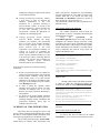
Figure 3.1 - Retrieve Climatic information from
database tables
Through a Data reader each dataset parameter
is written to a XML file. Following will portray the
creation of the XML file using XMLTEXTWRITER.
XmlTextWriter writer = new
XmlTextWriter(@"F:\Softwareproject\Myfina
lyearproject\cbr\CBR_Tester\WritingUserIn
put.xml",null);
writer.Formatting = Formatting.Indented;
writer.WriteStartDocument();
writer.WriteStartElement("Query");
writer.WriteAttributeString("CID",id)
Figure 3.2 – Creating an XML file and start writing the
document
Read Climatic details from XML file:
To retrieve data from an XML file, the method
XMLReader [13] was used to reads each node at a time.
3
To recognize each node XMLNodeType.Element and
XMLNodeType.Attributestring is used to read the value
specified under that Node.
switch (Reader.NodeType)
{
case XmlNodeType.Element:
name = (Reader.Name);
if (Reader.Name == "Query")
{
while
Reader.MoveToNextAttribute()
{
SID = (Reader.Value);
}
Figure 3.3 – Reading the XML file
For brevity, lengthy discussions related to the XML is
avoided, more information can be found in [13].
4.0 DESIGN OF TWO DIMENSIONAL
DRAWINGS USING GDI+
To achieve user friendliness in presenting
information to the user, 2D designs were incorporated.
GDI+ is quite a complex, challenging design library in
constructing changeable designs (E.g.: When ever user
changes roof details, design changes accordingly).For
more information on GDI+, refer [14].
Visualize different roof shapes and insulation
thicknesses
to
the
designer,
namespaces
System.Drawing.Drawing2D and System.Drawing
was incorporated. These namespaces provide basic
shapes such a lines, rectangles, circles, pies etc. In
order to design roof shapes in different angles, many
complex mathematical equations have to apply on the
mentioned basic shapes.
GraphicsPath myPath = new GraphicsPath();
Rectangle pathRect = new
Rectangle(181,198, 45,45);
myPath.AddRectangle(pathRect);
Pen myPen = new Pen(Color.Transparent,
2);
e.Graphics.FillPath(mySolidBrush,
myPath);
e.Graphics.DrawPath(myPen, myPath);
Y = (referen - sweepAngle);
Z = (Y/5);
startAngle = System.Convert.ToInt64((Z *
2.5)+ referen);
}
else if (sweepAngle >= referen)
{
Y = (sweepAngle - referen);
Z = (Y/5);
startAngle =
System.Convert.ToInt64(referen -(Z*2.5));
}
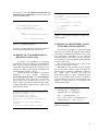
Figure 4.2 – Drawing the roof shapes according to the
specified angles.
5.0 DESIGN OF MICROMEDIA FLASH
TWO DIMENSIONAL DESIGNS
This concept of designing in macromedia flash
allows the user to portray the optimum results obtained
in the form of a graphical representation of the overall
roof architecture. Presentation of roof materials,
insulation materials and ceiling materials along with
the roof design is created using Macromedia flash MX
and Active Server [15].
This was developed using action script [15] and
designs are generated in movie files.
Manipulating values obtained from the program
are stored in action variables. Images and shapes are
stored as objects, which are manipulated according to
the variable values specified and place the
shapes/images on the X, Y plane. During the analysis
stage it was found that Flash cannot be extended to
create 3D drawings. This can be incorporated in to the
program by using Directive X in designing three
dimensional Drawings.
setProperty(line, _height, hypo);
setProperty(line_r, _height, hypo);
setProperty(line_rb, _height, hypo);
line_r_x = getProperty(line_r, _x);
line_r_x_tem = ((line_r_x)+Number(length));
setProperty(line_rb, _x, line_r_x_tem);
Figure 5.1 – Sample from action script.
Movie files generation.
Figure 4.1 – Designing roof shapes using rectangles and pies.
4
Professional/
Designer
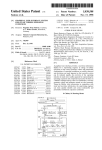
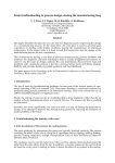
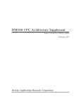
6.0 FUNCTIONAL BLOCK
6.1 COMPONENT DESIGN
In section 2.0 some of the key issues handled by
designing the optimum roof architecture and
insulations are highlighted. Investigations and surveys
are carried out on existing applications and ongoing
research discovered a new mechanism of solving the
thermal discomforts using expert knowledge. The
model mainly categorized and described under five
major components.
o Data Extractor
o User Preference Module
o Fuzzy Decider
o Case Base Reasoner
o 2D Drawing Designer
Each Major Component will be sub divided into
sub components which will be described and discussed
in the next following section.
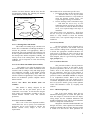
Fuzzy decider and the case base reasoner are the
key components in the system which presents with the
optimum results according thermal comfort condition
as well as the climatic details obtain per room in a
dwelling. Designer/professional will have to obtain
climate data, customer requirements and site details
through the Data Extraction component and then
acquiring preferences /problem from the customer by
the User Preference component. Customer
requirements, roof architecture preferences details also
thermal comfort, budget etc are fed in to the Case Base
Reasoner. This in turn will present with the optimum
roof architecture details. By Moving into the Fuzzy
Decider a customer will be able to obtain an
appropriate thermal insulation thickness per room in a
dwelling.2Dimensional designer will portray the
optimum roof details as well as insulation thicknesses
in graphical format also in charts.
Each component is further divided into sub
modules, where each module performs its task
independently. Communication between each
module will be handled through shared information.
Region Info
Customer Info
User Preference
Module
Customer
New House
(Plan Design)
Data Extractor
Fuzzy Decider
New House
(No Plan)
Site Info
Existing House
2D Drawing Panel
Case Base Resonner
6.1 - Overall Functional Block Diagram
6.1.1 Data Extraction
This particular module will be mainly targeted
at gathering raw information from external sources
such as regional & Climate Information from
Meteorology department or from professionals,
Customer Information & Dwelling Designs and finally
Site Details gathered during the site inspection. Site
Details will be then categorized into two sub modules,
new Dwelling designs and Existing Dwelling designs.
o
o
o
Climate Information
Customer Information
Site Information
New Dwelling Design
Plan available
Existing Dwelling Design
Plan not available
6.1.1.1 Climate Information
This particular feature is added to obtain climate
information to calculate the thermal comfort per
region. This will allow the professional/designer to
directly retrieve thermal comfort values for particular
customer site location. Here, it is able to extract climate
data from XML file formats (if a direct connection is
available with the Meteorology department) or
professional will be able to enter information by key in
data manually.
6.1.1.2 Customer Information
This will extract basic customer information like
customer name, address etc while assigning a customer
a unique identifier. Along with this information the
professional/Designer should input, whether the roof is
designed for a new house or an existing house.
Depending on the type of category, he will be placed in
the appropriate site module.
6.1.1.3 Site Information
This is one of the important sub modules,
where most of the other major components will be
accessed with in it. Site Information is categorized in to
three sub components .For an example when a
customer needs to obtain a solution for a existing house
he will be able to access this particular form for the
roof design solution. This sub module directly interacts
5
with the Case Base Reasoner and the Fuzzy Decider
for appropriate solutions. The following sub modules
will be discussed in wider context.
Site Information Sub
Module
Existing
House
New
House
Plan Design
No Plan
Design
Figure 6.1.1.1 – Decomposition of Site Information
Module
This module will be used in three specific areas.
1. In existing dwellings at the renovation stage
Will allow the user to key-in current
roof architecture details to verify whether it
meets the thermal comfort levels, user
required budget and usage of insulations.
2. In New dwellings at the Construction stage
Will allow the user to key- in, roof
architecture details specified in the plan to
verify whether it meets the thermal comfort
levels, user required budget and usage of
insulations.
User desired stage (User preference) – Will allow
the user to key-in, user preferred roof architecture
details to verify whether it meets the thermal
comfort levels, user required budget and usage of
insulations
6.1.1.5 Fuzzy Decider
6.1.1.3. a Existing House Sub Module
This module will mainly target customers who
need to find a comfortable roof through insulations or
renovate his particular roof appropriately. When a
professional visits to the particular site location he will
be able to gather information such as the roof details of
the existing house and the temperature, humidity. Air
velocity levels of the existing house. These climatic
conditions will be inspected in rooms that directly
touch the roof.
6.1.1.3.b New House Sub Module (Plan available)
This module is one of the sub modules of the
New House Module. This contains information about
customer’s who is willing to verify and design proper
roof architecture according to the thermal comfort
levels, budget and cooling, heating loads. This will
offer the customer an opportunity to verify whether the
drawn roof architecture provides adequate interior
thermal comfort.
6.1.1.3.c New House Sub Module (Plan not
available)
This module is mainly designed for the
customer’s who has no plan drawn prior to the
construction a new house. It will allow the designer
chose proper roof architecture according to the site
location thermal comfort levels and customer
preferences.
6.1.1.4 User Preference Module
This is one of the most important modules,
which allows the user to specify roof architecture
preferences and to verify whether it satisfies the
thermal comfort levels, budget or the user
requirements.
The fuzzy Decider will be designed only to
the existing site Information sub module. This will
extract climatic readings from a particular dwelling
to decide the appropriate insulation thickness for
each room in a dwelling. In order to decide on the
appropriate insulation thickness, a fuzzy module has
been designed, where it is governed using the fuzzy
logic principle [16].
6.1.1.6 Case Base Reasoner
This particular module is directly linked to
the User preference module. It will capture all the
preference parameters into the case base reasoning
module, where it will analyze the parameters with
the case parameters. Each case in the database is
weighted, based on the weights assigned at the user
preference module. Case base reasoner is designed
as an independent module. Based on the user
criteria, the appropriate case base module will be
overloaded. Weighted results will in turn transfer to
the User preference module, giving out the optimum
results and alternative results by weighing each
solution.
6.1.1.7 2D Drawing Designer
This is the centre module, where the two
dimensional drawing space is created. This panel will
allow the designer to look and feel the roof shapes,
ceiling shapes also the insulation thicknesses that
should be installed per room. This is used to transform
numeric or shapes into visualized form.
Integration of the Macromedia Flash MX was
through “Text files”, where optimum roof architecture
parameters captured at the Case Base Reasoner module
is written on to the text file. These parameters are
6
extracted by the Flash action scripts, which has been
described in 5.0.
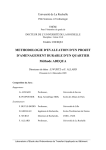
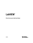
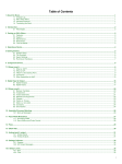
7.0 CASE BASE REASONNING
MODULE
Case base Module is categorized into 7 main
components in which each will be interacting
through number of items present and the their
fields. Basic Case base architecture is depicted
below [10].
Matching
Items Manager
Filter
Engine
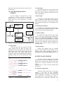
This will extract past case values such as records
and matches that with the user specified fields in the
XML. This specific segment will hold all the case
values in the database.
7.3 Filter Engine
According to the specified criteria (seen in
Figure 7.2) the cases stored in the items manager are
filtered by the filter engine. Along with the filtered
values, filtered field names are sent to Matching items
Manager.
7.4 Matching Items Manager
The filtered items obtained from the filter engine
and the similar items obtained from the Query reader
capture and passed to the Similarity Engine.
Query
Reader
XML File
7.2 Items Manger
Similarity
Engine
Items
Manager
Display
Manager
DB
Figure 7.1 – Case base reasoning module architecture
7.1 Query Reader
This will extract the user preferences and the
values specified from the XML file format. This
information will be categorized into filter criteria and
similar criteria .Filter criteria will be entered into the
filter engine where as the similar criteria and the
weights are entered in to the Matching Items Manager.
Reading the XML files has been described in section
4.0.
<!-Thermal Comfort Parameter -->
<C fieldname="thermalcomfort"
Operator="<=" Value="20" />
<C fieldname="thermalcomfort"
Operater="~" Value="28" />
<W fieldname="thermalcomfort"
Value="7"/>
- <!-Roof budget Filter Parameter -->
<C fieldname="budget" Operator="<="
Value="20000" />
<C fieldname="budget" Operator="~"
Value="65000" />
<W fieldname="budget" Value="10" />
Figure 7.2 – User specified values and fields
7.5 Similarity Engine
This segment will capture the filter items, similar
items as well as their weight from the matching item
manger. Using K-nearest algorithm [10], similarity
between the filter items from the database is matched
with the similar items obtain from the query reader.
This will in turn calculate the distance/ similarity as a
percentage. Each solution is ranked according to the
percentage found.
7.6 Display Manger
Similar items gathered from the similarity
engine are directly transferred to the database for easy
retrieval using stored procedures created by
System.Data and System.Data.SQLClient libraries.
8.0 FUZZY LOGIC MODULE
The Fuzzy decider component will extract
climatic data to decide on the appropriate insulation
thickness for a particular room. Please note that each
room will be evaluated separately in the fuzzy
module.
Algorithm Used: Center of Gravity defuzzification
method [16]
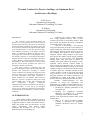
8.1 Fuzzifying Climatic data
When the climatic data enters in to the fuzzy
module, it will check for the appropriate
membership function for each climatic parameter
(Room Temperature, Humidity, air velocity and
Roof Temperature). Each membership function, a
membership value is calculated ( value).This value
7
will be passed to the inference engine with the
membership name.
Membership
value
µ
Very
Low
High
15 17 20
35 Climate data
string[] theTemp =
(GetMFTempName(TempValue).Split ('|'));
// membership name
string[] theHumid=
(GetMFHumidName(HumidValue).Split('|'));
string[]
theAirVel=(GetMFAirVelName(AirVelValue).S
plit('|'));
if (theTemp.Length == 2)
{
TempCheck1 = theTemp[1];
MembershipFuncnew(TempCheck1,TempValue
); // get membership value
Figure 8.1 – Obtaining membership value and
Membership name
8.2 Checking for the appropriate rules
The passed membership names and the
values for each climatic parameter will be evaluated
by running through each rule specified. Please note
that each rule is generated by identifying the
relationship between the climate and insulation
thicknesses provided by the professionals. (E.g If
Temp = High and Humidity = High and Air Velocity
= Low then the interior will be uncomfortable.
Therefore, thickness should be thick.) These rules
will be evaluated and the appropriate rules will be
fired [16].
8.3 Getting the appropriate thickness based on
the climate data
Appropriate thickness membership names and
the calculated membership values ( value) will be
extracted by the Inference engine procedure.
Applying these values in the output membership
function the appropriate thickness per room can be
obtained. Using Centre of Gravity method, each
membership function’s area will be calculated and
divided by the upper and lower boundaries of the
total thickness membership functions to obtain the
centre value. This will be deduced as the appropriate
thickness value for the specified climatic data.
9.0 UNDERLYING ISSUES
In this section, some of the more important
issues handled by the “RoofOpt” is discussed. As
mentioned in 1.0, there is an argument between
“designing optimum roof architecture based on thermal
comfort conditions” using mathematical models and
using artificial intelligence. There are a few software
applications developed using AI techniques to the
architectural community. This is possible only if there
are predefined algorithms exist in designing roof
architectures. To capture optimum results based on
thermal comfort, budget etc can be obtained through
professional knowledge, experience they have gain.
Also it is relevant to use research/experimental results
in determining the optimum solution.
In deciding the appropriate thermal insulation
thickness per room according to climatic conditions is
never possible using mathematical equation. Most of
the manufactures have their own R-values labeled per
region [11]. But, these values are not always true when
a particular site location is concerned also the house
architecture. Therefore, using professional knowledge
experience in deciding the appropriate thicknesses per
room will result in a proper solution suited for a
particular dwelling.
Currently, the RoofOpt presents with the
optimum solution by searching the highest weightage
assigned by the Case based reasoner module. In order
to automate the searching process of the optimum
result among the solutions, Genetic algorithm [16] can
be incorporated. We again stress the importance of
obtaining the optimum results among the solutions,
which is not completely automated.
10.0
IMPLEMENTATION
The *prototype was developed using .NET
Framework in C# programming language due to its
ability to create graphical designs, platform
independence and powerful graphical user interfaces.
SQL Server 2000 was chosen as Database Management
System because of it’s capability to create stored
procedures to perform the transaction automatically,
Optimizing application performance during data
retrieval, Recovery, security etc.
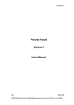
“RoofOpt” is implemented in three distinct
layers to support the development of three tier
architecture. Because of this nature, it was able to
achieve independence in each layer.
For example, changes carried out at the middle layer
or at the GUI layer will not be affected on the Data
*
For brevity, the GUI designs are not discussed in this
paper. However it can be found in reference [17] for
interested readers.
8
Layer. Here, the GUI Layer is consisting of Data
Extractor, User preference Module and displaying
the optimum results in three different format such as
graphical, tabular and 2D designs whereas the
middle layer will extract information from the GUI
layer and the Data layer to perform the particular
operation. The fuzzy decider, outputs will be directly
displayed on the GUI and saves in the Database. But
in the case of Case base Reasoner, the outputs will
be directly saved in the database and retrieved by the
GUI layer.
In order to decide on the appropriate
insulation thickness based on the climate
information captured per room, will be computed
using fuzzy logic algorithm.
GUI Layer
Data Link
Libraries
Middle Layer
Stored
Procedur
es
Fuzzy Decider
Module
Data Layer
XML
Files
Graphical
User
Interfaces
Data
Link
Libra Case Base
ReasonerModule
Retrieve
keyed-in
data
2 Dimensional
Data Base
Layer
Stored
Procedures
Designer
The GUI of the prototype has the following
capabilities:
or
key-in
11.0
regional
It is interesting and not altogether coincidental that this
project opens up a new vista to the concept of
“Thermal Comfort dwelling designs through optimum
roof architecture”, challenging the conventional
methodologies by incorporating new technologies to
tackle the problem. This project has discussed what
seems to be impossible, indeed feasible and practical
towards the betterment of the architectural community
and relevant to most personnel attempting to tackle this
problem. Many software tools exist, but most of the
tools concentrate on low energy buildings, energy
efficiency. Very few tools are designed to target on
“Thermal comfort in dwellings” which will it turn
achieve energy efficiency and cost effectiveness.
In order to address the issues on thermal discomforts,
energy crisis as well as economical issues arises in
third world countries, a new dwelling design tool was
proposed. The unstructured, heuristic nature of the
current methodologies paved the way to the proposed
project “Thermal Comfort achieved in passive houses
via roof architecture (RoofOpt)”. This project proposes
to develop an intelligent artifact which will determine
the optimum roof architecture according to thermal
comfort conditions in a dwelling.
The “RoofOpt” is researched in achieving a structured
design method and devise a proper solution through a
new design mechanism eliminating previous
mathematical models. Consequently, the tool will
present the optimal roof architecture and the
appropriate thermal insulation thicknesses and
materials for a given user specification.
climatic
Customer Information and inquires
12.0
Optimum roof architecture based on user
requirements
Optimum roof architecture obtained at the
renovation stage of the existing building
Insulation solution for an Existing dwelling
REFERENCES
1.
University of California “RESFEN 3.1 for
Calculating the Heating and Cooling Energy
Use of Windows in Residential Buildings”,
Home page, Jan.10 ,2003
(http://www.resfen.com/)
2.
Konstantinos Papamichael.
“Building Design Advisor”,Home page,
June. 21, 2001
(http://www.eere.energy.gov/buildings/to
ols_directory/software/bda.html)
Optimum roof architecture based the designed
roof architecture
CONCLUSION
Database
Figure 10.1 – Overall system architecture
Downloading
information
Two Dimensional design portrayed for the
selected optimum roof architecture
9
3.
Federspiel, C., R. Martin, and H. Yan
“Thermal
Comfort
Models
and
Complaint Frequencies, Dec. 20, 2003
(http://www.lema.ulg.ac.be/TOWNSCOP
E/townscope.html)
4.
“ASHRE Fundamentals Handbook”, Dec.
20,2003
(www.ceere.org/beep/docs/ASHRAE/C29
_txt_IP_rev1.doc)
5.
Swedish International Development
Cooptation Agency. “DEROB-LTH for
MS Windows, User Manual (version
99.01+3). [CD-ROM]. Feb. 28, 2004
6.
Nugroho Susilo. “Passive Design in WarmHumid?”, Feb. 20, 2004
7.
G.K. Garden. “Thermal Considerations in
Roof Design”, Jan. 12, 2004
(http://irc.nrc-cnrc.gc.ca/cbd/)
8.
Marek Obitko, “Introducton to genetic
algorithms”, Dec. 20,2003,
(http://cs.felk.cvut.cz/~xobitko/ga)
15. Nelson Marcos. “Fuzzy Logic
Description Detailed”, Home page,
Feb. 20, 2004,
(http://www.comp.nus.edu.sg)
16. Perera M.S.R., ``Thermal comfort for passive
dwellings via optimum roof architecture,’’
Final year project thesis, Informatics Institute
of Technology, Wellawatta, Sri Lanka, April
2004
9. Morgan Amelia A. Baldwin. “Case base
Reasoning”, Dec. 20,2003,
(http://accounting.rutgers.edu/raw/aies/w
ww.bus.orst.edu/faculty/brownc/aies/new
s-let/fall95/casebase.htm)
10. Welch Kevin. ”Insulation Fact Sheet”,
Jan. 10, 2004,
(http://www.ornl.gov)
11. Jayasinghe M Thishan R , Priyanandana
A.K.M “Thermally comfortable passive
houses for tropical uplands” , Research
project, June 2002
12. Darshan Singh.” XML for C# Programmers”,
Home page, March. 23, 2004
(http://www.PerfectXML.com)
13. Ferguson Jeff, Brian Petterson, Jason
Beres, Meeta Gupta. “C# programming
Bible”, March. 23, 2002
14. Macromedia, Inc, “Welcome to
Macromedia Flash MX”, Home page, March.
23, 2003
(www.macromedia.com)
10