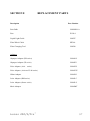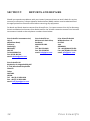
1
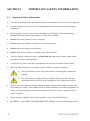
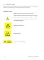
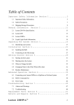
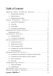
Lumen200/Lumen200S Lumen200Pro User Manual v1.2 Lumen 200/S/Pro™ 1 Table of Contents SECTION 1 1.1 1.2 1.3 3.3 3.4 3.5 3.6 4.3 4.4 4.5 2 GENERAL INFORMATION 9 9 9 9 9 10 LUMEN200 11 Identifying your System Installing your System 3.2.1 Installing the Bulb 3.2.2 Connecting to the Microscope Starting up the Lumen200 Working with the Lumen200 Shutting Down the Lumen200 When to Change the Bulb SECTION 4 4.1 4.2 4 6 8 Lumen 200/S/Pro Specification Lumen 200 Lumen 200S Lumen200Pro Liquid Light Guide Information SECTION 3 3.1 3.2 4 Important Safety Information Safety Precautions Shipping/Storage Precautions SECTION 2 2.1 2.2 2.3 2.4 2.5 IMPORTANT SAFETY INFORMATION 11 12 12 15 16 16 17 17 LUMEN200S 18 Identifying your System Installing your System 4.2.1 Installing the Bulb 4.2.2 Connecting to the Microscope 4.2.3 Connecting your Lumen200S to a PC 4.2.3.1 Install the USB-Com port for Lumen200S in Windows 7 4.2.3.2 Install the USB-COM port for Lument200S in WindowsXP 4.2.4 Connecting your Lumen200S to an OptiScan or ProScan System Starting up the Lumen200S Working with the Lumen200S 4.4.1 Using a Lumen200S as a standalone Light Source 4.4.2 Using a Lumen200S with a PC only 4.4.3 Using a Lumen200S with a PC and OptiScan/ProScan Controllers 4.4.4 Using a Lumen200S with TTL Inputs Shutting Down the Lumen200S 18 19 19 22 23 23 23 27 28 28 29 29 29 29 30 Prior Scientific 4.6 When to Change the Bulb 30 4.7 RS232 Command Set for Lumen200S 4.7.1 General Commands for the Lumen200S when connected to a PC 4.7.2 General Commands for the Lumen200S when connected via 31 31 32 SECTION 5 5.1 5.2 5.3 5.4 5.5 5.6 5.7 5.8 5.9 Identifying your System Installing your System 5.2.1 Installing the Bulb 5.2.2 Connecting to the Microscope 5.2.3 Connecting your Lumen200Pro to an OptiScan or ProScan System 5.2.4 Connecting your Lumen200Pro to an Prior PCI Controller Changing Filters in the Filter Wheel Starting up the Lumen200Pro Working with the Lumen200Pro 5.5.1 Using a Lumen200Pro as a standalone Light Source 5.5.2 Using a Lumen200Pro with a PC only 5.5.3 Using a Lumen200Pro with a PC and OptiScan/ProScan Controllers Shutting Down the Lumen200Pro When to Change the Bulb RS232 Command Set for Lumen200Pro Error Codes SECTION 6 6.1 6.2 LUMEN200PRO TROUBLESHOOTING Alarms and Warnings Troubleshooting 33 33 34 34 37 38 39 40 42 43 43 43 43 43 44 45 51 53 53 54 SECTION 7 REPLACEMENTS PARTS 57 SECTION 8 RETURNS AND REPAIRS 58 Lumen 200/S/Pro™ 3 SECTION 1 1.1 IMPORTANT SAFETY INFORMATION Important Safety Information. Use only as specified by the operating instructions or the intrinsic protection may be impaired. Keep this manual in a safe place as it contains important safety information and operating instructions. Before using the system, please follow and adhere to all warnings, safety and operating instructions located either on the product or in this User’s Manual. Do not expose the product to water or moisture. Do not expose the product to extreme hot or cold temperatures. Do not expose the product to open flames. Do not allow objects to fall on or liquids to spill on the product. All of the Lumen variants are class 1 and must only be connected to a power outlet which provides a protective earth (ground). Connect the AC power cord only to designated power sources as marked on the product. Make sure the electrical cord is located so that it will not be subject to damage. Always disconnect power from product before connecting the components together. Use only the power supply cord set provided with the system for this unit, should this not be correct for your geographical area, contact your supplier. Do not in any way attempt to tamper with the product, doing so will void the warranty, and may damage the system. This product does not contain consumer serviceable components, all repairs or services should be performed by Authorised Service Centres, contact your local dealer for details. Ensure that the ventilations slots in the controller case are free from blockages. WARNING: - Hg-LAMP CONTAINS MERCURY, Manage in Accord with Disposal Laws. 4 Prior Scientific WARNING: The method in which the lamps are disposed of must comply with the local rules & regulations for disposal of hazardous materials. Lamps may be return to Prior Scientific providing they are return in their original packaging. Before replacing a fuse, DISCONNECT THE EQUIPMENT FROM THE MAINS SUPPLY. Ensure that the mains switch / IEC socket/ mains plug is easily accessible to allow the unit to be switched off. Warnings: Eye damage may result from directly viewing the light produced by the lamp used in this product. Always make sure the light guide is properly inserted into the collimator which is firmly attached to the microscope using the adaptor provided and into the Lumen 200/Pro, before turning on the power to the unit. Caution: Never look into the emitting end of a light guide. The light could severely damage the cornea and retina of the eye if the light is observed directly. Appropriate eye shielding must be used at all times; clothing should be used to protect exposed skin. Never place the end of an emitting light guide near skin as this may result in burning and damage to the skin. Never place the end of an emitting light guide near a flammable substrate as sufficient power is emitted from the light guide to ignite flammable substances. Lumen 200/S/Pro™ 5 1.2 Safety Precautions. The Lumen 200 has protection features built in to avoid unintentional expose to UV radiation. In addition to this protection, please observe the following safety instructions. Definitions of Labels: Warning read instructions to determine possible hazard. Caution: Read these operating instructions fully before use and pay particular attention to sections containing this symbol. Use only as specified by the operating instructions or the intrinsic protection may be impaired. Warning surface may be Hot Warning UV Output Danger Electrical Shock hazard. 6 Prior Scientific Monitoring of the unit manual operation: The level of energy supplied is sufficient to ignite flammable substances. During operation the unit must be attended at all times by a qualified operator. The unit must not be left unattended while left on. If an operator leaves the work area of the unit, the lamp power must be switched off. Lumen 200/S/Pro™ 7 1.3 Shipping/Storage Precautions. NEVER SHIP THE UNIT WITH THE BULB INSTALLED. Always use the original packaging for shipping and storing purposes. Unpacking and Inspection Carefully unpack the unit and retain packaging to return equipment for servicing. If the equipment appears damaged in any way, return it to sales outlet in its original packaging. No responsibility for damage arising from the use of non-approved packaging will be accepted. Ensure all items and accessories specified are present. If not contact your local sales outlet. Lumen 200 Standard Contents: Lumen 200, Liquid Light Guide, Adaptor for specific microscope, Lumen 200 Bulb, Power Cord, Hex key. Lumen 200S Standard Contents: Lumen 200S, Liquid Light Guide, Adaptor for specific microscope, Lumen 200 Bulb, Power Cord, Shutter cable, RS-232 cable, USB cable, Hex key. Lumen 200Pro Standard Contents: Lumen 200Pro, Lumen 200/Pro Manual, Liquid Light Guide, Adaptor for specific microscope, Lumen 200 Bulb, Power Cord, Two Filter Wheel Cables, Shutter cable, Filter Wheel tool, Hex key. 8 Prior Scientific SECTION 2 2.1 GENERAL INFORMATION Lumen200 /S /Pro Specification. Power: Universal integral Power Supply: Input 110-240V, 50/60Hz Use within ambient temperature range: 18-28 oC. Required clearance: 100mm minimum. 2.2 Lumen200. The Lumen200 version of the Lumen series is a stand-alone standard unit and is furnished with a manual 6 position shutter, (0, 10, 25, 50, 75,and 100%). The Lumen200 contains a 200 Watt Metal halide bulb which is temperature controlled. The bulb is self-aligning and is coupled via special optics to the liquid light guide, which transfers the light to the microscope. For each major make of microscope an adaptor is available to connect the liquid light guide to the microscope. 2.3 Lumen200S. The Lumen200S version of the Lumen series contains an integrated high speed shutter that can be controlled via the shutters ports of Prior ProScan and OptiScan controllers, USB, RS2323 or TTL. It can also operate as a stand-alone standard unit and is furnished with a manual 6 position shutter, (0, 10, 25, 50, 75, and 100%). The Lumen200S contains a 200 Watt Metal halide bulb which is temperature controlled. The bulb is self-aligning and is coupled via special optics to the liquid light guide, which transfers the light to the microscope. For each major make of microscope an adaptor is available to connect the liquid light guide to the microscope. 2.4 Lumen200Pro. The Lumen200Pro version of the Lumen series contains a 6 position filter wheel and an advanced shutter (0-100% in 1% increments). The filter wheel and shutter require an external controller, it is recommended that this is either the Prior ProScan, PCI card, or the OptiScan II that will control these accessories. The Lumen200Pro contains a 200 Watt metal halide bulb which is temperature controlled. The bulb is self-aligning and is coupled via special optics to the liquid light guide, which transfers the light to the microscope. For each major make of microscope an adaptor is available to connect the liquid light guide to the microscope. NOTE: To have manual control of the filter wheel, shutter and light attenuation of the Lumen 200/S/Pro™ 9 Lumen200Pro you must have a ProScanIII and a PS3J100 interactive joystick. The ProScanII and Optican can only control these features via software. 2.5 Liquid Light Guide Information. Liquid light guides have a limited lifetime, independently of whether they are stored or in use. However, lifetime may vary depending on climatic conditions. Cold and humid environments will extend lifetime, hot and/or dry environments will shorten it. Though the outstanding UV performance will not markedly degrade during usage, we recommend that the light guide is replaced in advance of the expected lifetime of expiration. Final degradation is generally caused by the formation of bubbles in the liquid, and optical output may then drop very rapidly. Approximate lifetime: 4 years Suggested replacement time: 3 years Figures based on 23oC and 60% humidity. General usage temperature range: Min +5oC/41oF Max: +30oC /+86oF Should the temperature limits be exceeded the likely damage is the formation of bubbles inside the liquid. These may be reabsorbed if the light guide is stored at room temperature for several days. 10 Prior Scientific SECTION 3 3.1 Lumen200 Identifying your system. The Lumen200: Display Alarm reset Button Manual Shutter Control Collimator Power Switch Liquid Light Guide connection Microscope Adaptor Liquid Light Guide Light Guide Locking Nut Protective cap Quartz window Focus Locking Ring Microscope Adapter Fig 1 - The Liquid Light Guide Lumen 200/S/Pro™ Fig 2 – Lumen Collimator & Adapter 11 3.2 Installing your system. 3.2.1 Installing the Bulb Required equipment: Lumen 200, Hex Key, Prior LM200B1-A Bulb Warning: Only use Prior LM200B1-A bulbs, failure to do so may cause damage to the unit. Do not touch the inside of the reflector of the bulb. The bulb is delicate, handle with care. Instructions: 1. Do not connect the unit to the mains supply. (If the Lumen200 has been previously switched on, wait for 30 mins to allow bulb to cool). 2. Find a flat surface and place the Lumen200 upside down on the surface. 3. Unscrew the four Hex screws and remove the panel, as indicated in Figure 3 below. Hex Screws Figure 3 - Bulb Housing. 12 Prior Scientific Remove bulb from Carton : a. Open top of Carton b. Remove V-shaped Cardboard Holder c. Push Cardboard Flaps back d. Lift bulb out of carton. 4. Turn the bulb so that the cables and connector hang down into the bulb chamber. Plug the brown connector on the bulb into power socket in bulb housing; ensure it is pushed firmly into position. 5. This will orientate the bulb with the PCB and data connector socket facing upwards (Fig 6). 6. Locate the bottom of the bulb (as indicated in Fig 5 into the groove in the bottom (lamp house clamp (Fig 4) of the lamp housing. Lamp Spring Restraint Lamp Spring Data Connector Bottom Locating Groove Power Socket Fig 4 - The Bulb Housing Internals Lumen 200/S/Pro™ 13 Data Connector Power Connector Bottom 4.1d: of the Bulb Figure Lumen Bulb. Fig 5 - The LM375 Bulb 7. Lift the spring towards the bulb, as you do so the bulb will be pushed into the correct position, click the springs all the way into the Lamp Spring Restraints. (see Fig 6). Lamp Spring Restraint Lamp Spring Fig 6: Lamp Spring Restraint. 8. The bulb is now firmly held vertically in place. 9. Plug Data connector into its socket on the PCB. 10. Replace the bulb housing cover and replace the four hex screws. 14 Prior Scientific Data Connector Fig 7 - The Data Connector 3.2.2 Connecting to the Microscope Once the bulb is installed (see section 3.2.1), the Lumen200 is ready to be connected to the microscope. 1. Place the Lumen200 in a safe location and ensure none of the fan outputs are obstructed. 2. Unpack the liquid light guide from the foil packaging and remove both plastic caps from the light guide. Note: It is important to remove the caps before connecting to the light guide to avoid damage on power up. 3. Unscrew the connector on the front of the Lumen200, and insert the Light guide. a. Ensure the light guide is fully inserted into the Lumen200, the light guide should be inserted by 58mm. 4. Tighten the connector unit resistance is felt, the light guide is now firmly held in the Lumen200 connector. Lumen 200/S/Pro™ 15 5. Locate the collimating lens supplied to attach the light guide onto the microscope, loosen the screw on the back of the collimating lens. Firmly push the light guide into the hole ensuring it has reached it end stop and tighten the screw. 6. The Lumen is supplied with a collimating lens specifically designed to fit your microscope, the supplied collimating lens will only fit the specified make of microscope. 7. The illumination can be optimized by focusing the beam by adjusting the distance between the fibre tip and the microscope by unscrewing the collimator. The silver locking ring and then be used to fix the collimator into the optimum position (see Fig 2). 3.3 Starting Up the Lumen200 Warning: Do not power up the Lumen200 without the light guide attached to both the Lumen200 and microscope. Only power up the Lumen200 when it is installed on a level surface. 1. Ensure the light guide is attached to both the Lumen200 and microscope. 2. Connect the power cable to the Lumen200. 3. Switch the Lumen200 power switch on. 4. Allow approximately 5 minutes for light to reach operational temperature. 5. Do not power down the unit within 10 mins of power up. This may reduce the effective lifetime of the bulb. 3.4 Working with the Lumen200 The Lumen200 is a manual light source. Attenuation of the light can be achieved by use of the manual shutter control knob on the front of the unit. Illumination can be set to 0%, 10%, 25%, 50%, 75% or 100% (Fig 8). Turning the knob to the left increases the intensity and turning to the right decreases intensity. 16 Prior Scientific Manual Shutter Control knob Fig 8 – Intensity Control Knob 3.5 Shutting down the Lumen200 The following warnings apply as damage to the bulb may result if instructions not followed. Warning: Do not shut the unit down within 10 minutes of powering up the unit. Warning: After shutting down the unit, allow 10 minutes before re-powering up or changing the bulb. Failure to do so is likely to result in damage to the bulb. 3.6 When to Change the bulb The Lumen200 Bulb is installed with a timer chip which counts the hours that this specific bulb has been activated. Once the bulb reaches the recommended lifetime of 2000 hours, an alarm will sound on the Lumen200. It is recommended that the bulb is changed at this point. This alarm can be silenced using the button situated to the left of the display panel on the front of the lumen. Once a bulb has reach 2000 hours the alarm will sound on power up of the Lumen200 until the bulb is changed. Lumen 200/S/Pro™ 17 SECTION 4 4.1 Lumen200S Identifying your system. Fig 9 - The Lumen200S: Alarm reset Button Display Manual Shutter Control Power Socket Power Switch Liquid Light Guide socket Fig 10 - The Lumen200S Side Panel USB Socket Lamp On/Off TTL connector Fuse Sockets RS232 Connector Shutter connector Shutter TTL connector Power Socket 18 Prior Scientific 4.2 Installing your system. 4.2.1 Installing the Bulb Required equipment: Lumen200S, Hex Key, Prior LM200B1-A Bulb Warning: Only use Prior LM200B1-A bulbs, failure to do so may cause damage to the unit. Do not touch the inside of the reflector of the bulb. The bulb is delicate, handle with care. Instructions: 1. Disconnect the Lumen200S from the mains supply, (If the Lumen200S has been previously switched on, wait for 30 mins to allow bulb to cool). 2. Find a flat surface and place the lumen upside down on the surface. 3. Unscrew the four Hex screws and remove the panel, as indicated in Figure 11 below. Hex Screws Fig 11- Bulb housing. Lumen 200/S/Pro™ 19 Remove bulb from Carton : a. Open top of Carton b. Remove V-shaped Cardboard Holder c. Push Cardboard Flaps back d. Lift bulb out of carton. 4. Turn the bulb so that the cables and connector hang down into the bulb chamber. Plug the brown connector on the bulb into power socket in bulb housing; ensure it is pushed firmly into position. 5. This will orientate the bulb with the PCB and data connector facing upwards. 6. Locate the bottom of the bulb (as indicated in figure 13 below) into the groove in the bottom (lamp house clamp Figure 12) of the lamp housing. Lamp Spring Restraint Data Connector Lamp Spring Power Socket Bottom Locating Groove Figure 12 - Bulb Housing Internals. 20 Prior Scientific Data Connector Power Connector Figure 4.1d: Lumen Bulb. Bottom of bulb Fig 13 - The LM375 Bulb 7. Lift the spring towards the bulb, as you do so the bulb will be pushed into the correct position, click the springs all the way into the Lamp Spring Restraints. (see Figure 4.1e). Lamp Spring Restraint Lamp Spring Fig 14 - The Lamp Spring Restraint 8. The bulb is now firmly held vertically in place. 9. Plug Data connector into socket on the PCB. 10. Replace the bulb housing cover and replace the four hex screws. Lumen 200/S/Pro™ 21 Data Connector Fig 15 - The Data Connector 4.2.2 Connecting to the Microscope Once the bulb is installed (see section 4.2.1), the Lumen200S is ready to be connected to the microscope. 1. Place the Lumen200S in a safe location and ensure none of the fan outputs are obstructed. 2. Unpack the liquid light guide from the foil packaging and remove both plastic caps from the light guide. Note: It is important to remove the caps before connecting to the light guide to avoid damage on power up. 3. Unscrew the connector on the front of the Lumen200S, and insert the Light guide. a. Ensure the light guide is fully inserted into the Lumen200S, the light guide should be inserted by 58mm. 4. Tighten the connector unit resistance is felt, the light guide is now firmly held in the Lumen200S connector. 22 Prior Scientific 5. Locate the collimating lens supplied to attach the light guide onto the microscope, loosen the screw on the back of the collimating lens. Firmly push the light guide into the hole ensuring it has reached it end stop and tighten the screw. 6. The Lumen is supplied with a collimating lens specifically designed to fit your microscope, the supplied collimating lens will only fit the specified make of microscope. 7. The illumination can be optimized by focusing the beam by adjusting the distance between the fibre tip and the microscope by unscrewing the collimator. The silver focus locking ring and then be used to fix the collimator into the optimum position. (See Fig 2) 4.2.3 Connecting your Lumen200S to a PC The Lumen200S can be controlled directly from a PC without the need of an external controller such as an OptiScan or ProScan. The Lumen200S will emulate a Prior Proscan controller with one shutter connected, and can be set up in 3rd party software this way. The PC can be detected via USB or RS232 cable. If the USB cable requires a driver then please go the following section on the Prior Scientific website and download PL200/ES10ZE USB Drivers; http://www.prior.com/downloadcentre/dc_software.html 4.2.3.1 Installing the USB-COM port for Lumen200S in Windows 7 Plug in the USB cable to the Lumen200S and the computer, power on the Lumen200S. Windows 7 should automatically recognize the device and install the appropriate drivers. 4.2.3.2 Installing the USB-COM port for Lumen200S in Windows XP Plug in the USB cable to the Lumen200S and the computer, power on the Lumen200S. Lumen 200/S/Pro™ 23 When prompted select No, not at this time, then click NEXT. Fig 16 Select “Install from a list or specific location (advanced)” Fig 17 24 Prior Scientific Browse to the location of Eval232R, click NEXT. Fig 18 Fig 19 The Eval232R folder can be found in the SDK. This can be downloaded from www.prior.com. Fig 20 Contents of SDK. Lumen 200/S/Pro™ 25 Fig 21 Click Finish. 26 Prior Scientific 4.2.4 Connecting your Lumen 200S to an OptiScan or ProScan System The Lumen 200S can work together with a Proscan or Optiscan controller assuming you have an active shutter connection, see Fig 22. 1. Connect Shutter Cntlr port on the Lumen200S to the Shutter port on the ProScan or OptiScan II system using the cables provided. a. It is not important which shutter ports are used on the Controller, but this should be noted for use with the command set described below, or for setting up your 3rd party software. b. Switch on the Controller, your Lumen 200S is now ready to accept commands. Lumen 200S Shutter connections OptiScan Controller Shutter connections ProScan Controller Shutter connections To the Lumen 200S To the Controller Fig 22 – The Lumen200S Connections Lumen 200/S/Pro™ 27 4.3 Starting Up the Lumen 200S Warning: Do not power up the lumen without the light guide attached to both the Lumen200S and Microscope. Only power up the Lumen200S when it is installed on a level surface. 1 Ensure the light guide is attached to both the Lumen200S and Microscope. 2 Connect the power cable to the Lumen200S. 3 Switch the Lumen power switch on. 4 Allow approximately 5 minutes for light to reach operational temperature. 5 Do not power down the unit within 10 mins of power up. This may reduce the effective lifetime of the bulb. 4.4 Working with the Lumen200S The Lumen200S can use used either as a standalone unit, controlled directly though a PC or controlled by a PC via a Proscan III controller with a shutter connector. The condition of the shutter is indicated on the display panel on the front of the device (see Fig 23), along with the bulb on time in hours. O = Shutter open. S = Shutter closed. Shutter Status Indicator Fig 23 – Lumen200S Display Panel 28 Prior Scientific 4.4.1 Using a Lumen 200S as a standalone Light Source By default the Lumen200S starts with the motorized shutter in the open position, you can hear the shutter opening upon start up. If the unit is used as a standalone device, then light intensity can be controlled manually with the control knob on the front of the unit. Turning the knob to the left increases the intensity and turning to the right decreases intensity. 4.4.2 Using a Lumen200S with PC only The Lumen 200S shutter can be controlled via a PC, with the following direct connections; USB, RS232 and TTL. The Lumen200S behaves as a Proscan Controller with a single shutter, and can be set up in your software this way. See commands in section 4.7 RS232 command set for general commands for the Lumen 200S when connected directly to the PC. Alternatively refer to your software manual if you are controlling the Lumen200S with 3rd party software. NOTE: Intensity can only be set using the manual shutter control knob on the front of the unit. 4.4.3 Using a Lumen200S with PC and OptiScan/ProScan Controllers The Lumen200S shutter can be controlled via the OptiScan / Proscan controllers. Connect the Lumen200S to the shutter port of the Prior controller using a standard Prior shutter cable. The Prior controller can be controlled via the PC with either of the following connections, USB or RS232. NOTE: Intensity can only be set using the manual shutter control knob on the front of the unit. 4.4.4 Using a Lumen200S with TTL Inputs Two TTL inputs are available on the side panel of the Lumen200S. The first of the TTL inputs can be used to OPEN or CLOSE the shutter. It uses 0V to 5vdc, were LOW is to OPEN the shutter and HIGH is to CLOSE the shutter. The second of the TTL inputs can be used to turn OFF the bulb only. It uses 0v to 5vdc, were LOW is to turn OFF the bulb. Note the Bulb cab only be turned back on by turning the mains switch OFF and ON again. The TTL can not be used to switch the bulb back ON. Lumen 200/S/Pro™ 29 4.5 Shutting down the Lumen200S The following warnings apply as damage to the bulb may result if instructions not followed. Warning: Do not shut the unit down within 10 minutes of powering up the unit. Warning: After shutting down the unit, allow 10 minutes before re-powering up or changing the bulb. Failure to do so is likely to result in damage to the bulb. 4.6 When to Change the bulb The Lumen200S Bulb is installed with a timer chip which counts the hours that specific bulb has been activated. Once the bulb reaches the recommended lifetime of 2000 hours, an alarm will sound on the lumen. It is recommended that the bulb is changed at this point. This alarm can be silenced using the button situated to the left of the display panel on the front of the Lumen200S. Once a bulb has reach 2000 hours the alarm will sound on power up of the Lumen until the bulb is changed. 30 Prior Scientific 4 . 7 RS232 Command Set for Lumen200S A description of how to connect to the ProScan or OptiScan systems is supplied in the OptiScan II and ProScan II manual. The following is the RS232 commands applicable to the Lumen 200Pro. 4.7.1 General Commands for the Lumen 200S when connected to the PC Command ? Arguments Response (All end with <cr>) Description None Text string Reports information about the peripherals currently connected to the controller. The information end is always a line saying END This allows for the addition of extra fields of information without effecting application software. Users should always read lines in until the END is seen. A typical response is from Lumen 200S shown below PROSCAN INFORMATION DSP_1 IS NOT FITTED DSP_2 IS 3 AXIS STEPPER VERSION 0.0 DRIVE CHIPS 111000 JOYSTICK NOT FITTED STAGE = NONE FOCUS = NONE FOURTH = NONE FILTER_1 = NONE FILTER_2 = NONE SHUTTERS = 001 LED = 0000 AUTOFOCUS = NONE VIDEO = NONE HARDWARE REV A END VER None Text String Returns the version of the code fitted to the unit Eg. LumenShutter V2.5c VERSION None Text string Returns the Issue number. Eg. 025 Lumen 200/S/Pro™ 31 BULBTIME None Text string Returns the bulb lifetime as shown below; HOURS = 20 MINUTES = 30 END Showing bulb lifetime of 20 hours and 30 minutes. UNIT UNIT None 0 Text String R Returns the status of the Lumen200S UNIT = 1 UNIT = O END END For Bulb ON For Bulb OFF Turns the bulb OFF. It returns a response R on completion. NOTE:- The bulb can only be turned on again by turning the mains switch OFF and ON again. 8 S,C R Opens or closes the shutter S If shutter is not If C is 0 the shutter is opened, fitted E,20 will be If C is 1 the shutter is closed. returned 8 S 0,1 eg 8,1,0 the shutter is closed Returns the status of shutter S 0 the shutter is opened, 1 the shutter is closed. 32 Prior Scientific 4.7.2 General Commands for the Lumen 200S when connected via OptisScan / ProScan Controllers Command Argument s Response Description (All end with <cr>) 8 s,c[,t] R If shutter s is not fitted E,20 will be returned 8 s Shutter s c If shutter s is not fitted E,20 will be returned Text string Prints information about shutter‘s’ (s is a value between 1 and 3). The information end is always a line saying END. This allows for the addition of extra fields of information without effecting application software. Users should always read lines until the END is seen in order to maintain compatibility. Example SHUTTER_1 = NORMAL DEFAULT_STATE=CLOSED END SHUTTER_2=NONE END Lumen 200/S/Pro™ Opens or closes the shutter s (value ‘1’ ‘2’ or ‘3’), if c is 0 the shutter is opened, 1 it is closed. The optional argument t is used to open/close the shutter for a time t milliseconds. Returns status c of shutter s 33 SECTION 5 5.1 Lumen200PRO Identifying your system. Alarm reset Button Display Power Socket Power Switch Liquid Light Guide socket Fig 24 – The Lumen200Pro Fuse Sockets Filter Wheel connector Shutter /Light Atttenuation connector Lamp On/Off connector Power Socket Fig 25 – The Lumen200Pro Side Panel 34 Prior Scientific 5.2 Installing your system. 5.2.1 Installing the Bulb Required equipment: Lumen200Pro, Hex Key, Prior LM200B1-A Bulb Warning: Only use Prior LM200B1-A bulbs, failure to do so may cause damage to the unit. Do not touch the inside of the reflector of the bulb. The bulb is delicate, handle with care. Instructions: 8. Disconnect the Lumen200Pro from the mains supply, (If the lumen has been previously switched on, wait for 30 mins to allow bulb to cool). 9. Find a flat surface and place the lumen upside down on the surface. 10. Unscrew the four Hex screws and remove the panel, as indicated in Figure 26 below. Hex Screws Figure - 26 Bulb housing. Lumen 200/S/Pro™ 35 Remove bulb from Carton : a. Open top of Carton b. Remove V-shaped Cardboard Holder c. Push Cardboard Flaps back d. Lift bulb out of carton. 11. Turn the bulb so that the cables and connector hang down into the bulb chamber. Plug the brown connector on the bulb into power socket in bulb housing; ensure it is pushed firmly into position. 12. This will orientate the bulb with the PCB and data socket facing upwards. 13. Locate the bottom of the bulb (as indicated in figure 28 below) into the groove in the bottom (lamp house clamp Figure 27) of the lamp housing. Lamp Spring Restraint Lamp Spring Bottom Locating Groove Data Connector Power Socket Fig 27 – The Bulb Housing Internals 36 Prior Scientific Data Connector Power Connector Figure 4.1d: Lumen Bulb. Bottom of bulb Fig 28 – The LM375 Bulb 14. Lift the spring towards the bulb, as you do so the bulb will be pushed into the correct position, click the springs all the way into the Lamp Spring Restraints. (See Figure 29). Lamp Spring Restraint Lamp Spring Fig 29 – The Lamp Spring Restraint 15. The bulb is now firmly held vertically in place. 16. Plug Data connector into its socket on the PCB. 17. Replace the bulb housing cover and replace the four hex screws. Lumen 200/S/Pro™ 37 Data Connector Fig 30 – The Data Connector 5.2.2 Connecting to the Microscope Once the bulb is installed (see section 5.2), the Lumen200Pro is ready to be connected to the microscope. 1. Place the Lumen200Pro in a safe location and ensure none of the fan outputs are obstructed. 2. Unpack the liquid light guide from the foil packaging and remove both plastic caps from the light guide. Note: It is important to remove the caps before connecting to the light guide to avoid damage on power up. 3. Unscrew the connector on the front of the Lumen200Pro, and insert the Light guide. a. Ensure the light guide is fully inserted into the Lumen200Pro, the light guide should be inserted by 58mm. 4. Tighten the connector unit resistance is felt, the light guide is now firmly held in the Lumen200 Pro connector. 5. Locate the collimating lens supplied to attach the light guide onto the microscope, loosen the screw on the back of the collimating lens. Firmly push the light guide into the hole ensuring it has reached it end stop and tighten the screw. a. The Lumen200Pro is supplied with a collimating lens specifically designed to fit your microscope, the supplied collimating lens will only fit the specified make of microscope. 38 Prior Scientific 5.2.3 Connecting your Lumen200Pro to a OptiScan or ProScan System The Lumen200Pro requires two filter wheel connections to a ProScan II or OptiScan II system. Connecting your system: 1 Switch off the ProScan or OptiScan II controller. 2. Connect Filter Wheel, Shutter port and Lamp ON/OFF (Optional) on the Lumen to the Filter 1 and Filter 2 and Shutter port on the ProScan or OptiScan II system using the cables provided. a. It is not important which Filter connections are used on the Controller, but this should be noted for use with the command set described below, and for any 3rd party software . b. Tighten the screws to fix the cables in position. 3. Switch on the Controller, your Lumen200Pro is now ready to accept commands. a. It is not necessary to switch the Lumen200Pro power on to control the Shutter and Filter Wheel, these are powered by the attached controller. Fuse Filter Wheel Lamp on/off Power Socket Light Attenuator/Shutter Fig 31 - Controller attachments for Lumen 200Pro. Lumen 200/S/Pro™ 39 5.2.4 Connecting your Lumen 200Pro to Prior PCI controller The Lumen200Pro requires two filter wheel connections to a Prior PCI system. Connecting your system: 1. Switch off the PCI controller/computer. 2. Connect the Attenuator/shutter to “FILTER 1” using the cables provided. a. Tighten the screws to fix the cables in position. 3. Connect the Filter Wheel to “FILTER 2” using the cables provided. a. Tighten the screws to fix the cables in position. 4. Connect lamp ON/OFF to “Shutter 1” connection using cable provided, (Optional). a. If connected lamp default to OFF. 5. Switch on the controller and computer, your Lumen200Pro is now ready to accept commands. a. It is not necessary to switch the Lumen200Pro power on to control the Shutter and Filter Wheel, these are powered by the attached controller. 40 Prior Scientific 5.3 Changing Filters in the Filter Wheel The filter wheel can hold up to 6, 25mm filters; these are held in position using the standard Prior locking ring. Changing a Filter: Equipment required: Lumen200Pro, Filter, Prior Filter block tool, flat head screw driver. 1. Disconnect the Lumen from mains power and from the controller. 2. Ensure the unit has been allowed to cool for 30mins. 3. Place the unit on a flat surface with empty space in front of the unit. 4. Unscrew the 3 screws as indicated in Fig. 32 Fixing Screws Fig 32 – The Lumen200 Lumen 200/S/Pro™ 41 5. Lift the top of the unit, applying particular pressure to the front right corner to disconnect the internal connector. See Fig 32. Filter Wheel Internal Connector Fig 33 – The LumenPro200 Filter Wheel Compartment It is important to try and lift the cover from the Lumen200Pro as straight up as possible. This makes it easier to replace as it minimizes the stress on the internal connector. 6. Turn the filter wheel until the desired filter position is reached. The filter position is indicated in by the filter number which is displayed on the top left of the filter hole. (Fig 34) Filter Locking Ring Filter Number Fig 34 – The LumenPro200 Filter Wheel co 42 Prior Scientific 7. Using the Prior Filter block tool unscrew the filter ring, making sure to locate the two lugs in the filter block tool into the two holes of the filter ring. 8. Remove the old filter; replace the new filter taking care not to place finger prints on the filter. 9. Using the Prior Filter block tool screw the filter ring to hold the filter. Be careful; not to over tighten the filter ring; some filters will expand when heated by the light. 10. Repeat for all required filters. Remember to record the position of each filter for use with your software. 11. Replace top of unit, ensuring the internal connector is aligned and replace screws. 12. Reconnect controller, check that the filter wheel is moving. 13. Reconnect Lumen200Pro mains power. Starting Up the Lumen200Pro Warning: Do not power up the lumen without the light guide attached to both the Lumen200Pro and microscope. Only power up the Lumen200Pro when it is installed on a level surface. 1 Ensure the light guide is attached to both the Lumen200Pro and microscope. 2 Connect the power cable to the Lumen200Pro. 3 Switch the Lumen200Pro power switch on. 4 Allow approximately 5 minutes for light to reach operational temperature. 5 Do not power down the unit within 10 mins of power up. This may reduce the effective lifetime of the bulb. Lumen 200/S/Pro™ 43 5.4 Working with the Lumen 200Pro The Lumen200Pro can be controlled manually with the use of the PS3J100 interactive control centre and a Proscan III controller. Alternatively it can be controlled via software with either a Proscan or Optiscan controller. 5.4.1 Using a Lumen200Pro as a standalone light source It is not possible to use the Lumen200Pro as a standalone light source without a Prior controller. 5.4.3 Using a Lumen200Pro with PC and OptiScan/ProScan Controllers The Lumen200Pro can be controlled via the OptiScan / Proscan controllers using a standard Prior filter wheel and shutter cables. See section 5.2.2 Connecting your Lumen200Pro to an Optiscan or Proscan system. On ProscanIII system the filterwheel and light attenuation (shuttering) can be controlled manually via the PS3J100 interactive control center, or with software commands. On ProscanII and Optiscan II system the light attenuation (shuttering) can only be controlled via software commands. If you use the Lamp ON/OFF connector to turn off the bulb after experiments the Lumen200Pro can only be turned back on by turning the mains switch OFF and ON again. 5.5 Shutting down the Lumen200Pro The following warnings apply as damage to the bulb may result if instructions not followed. Warning: Do not shut the unit down within 10 minutes of powering up the unit. Warning: After shutting down the unit, allow 10 minutes before re-powering up or changing the bulb. Failure to do so is likely to result in damage to the bulb. 44 Prior Scientific 5.6 When to Change the bulb The Lumen200Pro Bulb is installed with a timer chip which counts the hours that specific bulb has been activated. Once the bulb reaches the recommended lifetime of 2000 hours, an alarm will sound on the lumen. It is recommended that the bulb is changed at this point. This alarm can be silenced using the button situated to the left of the display panel on the front of the Lumen200Pro. Once a bulb has reach 2000 hours the alarm will sound on power up of the Lumen until the bulb is changed. Lumen 200/S/Pro™ 45 6.3 RS232 Command Set A description of how to connect to the ProScan or OptiScan systems is supplied in the OptiScan II and ProScan II manual. The following is the RS232 commands applicable to the Lumen 200Pro. General Commands for identifying the Lumen200Pro. Identify which Filter Wheel port the Shutter and Filter Wheel are connected to using the “?” command described below. Command Arguments Response Description (All end with <cr>) $ a decimal Reports status as a decimal number and gives motion status of number the Filter Wheel or Shutter of the Lumen Attached to the controller. After binary conversion convention is as follows:F2 F1 A Z Y X D05 D04 D03 D02 D01 D00 Parameters “$,a” where a is the axis or resource F - Filter wheels F1 - Filter wheel 1 F2 - Filter wheel 2 When the optional parameter is used the binary word is just for the axis requested. F is for filters (both Filter Wheel and Shutter) and would return 0 to 3 depending on if they are in use. 46 Prior Scientific ? None Text string Reports information about the peripherals currently connected to the controller. The information end is always a line saying END This allows for the addition of extra fields of information without effecting application software. Users should always read lines in until the END is seen. A typical response is shown below OPTISCAN INFORMATION DRIVE CHIPS 11111 JOYSTICK ACTIVE STAGE = NONE FOCUS = NONE FILTER_1 = LLG_SHUTTER FILTER_2 = LLG_FILTER SHUTTERS = 000 END Lumen 200/S/Pro™ 47 The filter wheel installed in the Lumen Pro accepts the following commands. Command Arguments Response Description (All end with <cr>) 7 w, f if f = F the If f is a number move filter wheel w to filter position f. current if f is a ‘N’ move filter wheel w to next filter. filter else R If f is a ‘P’ move filter wheel w to previous filter. If no wheel If f is a ‘F’ report current filter on filter wheel w. is fitted if f is a ‘H’ performs a home routine. E,17 will be If f is ‘A’ wheel will auto home on controller startup returned. If f is ‘D’ wheel will NOT auto home on startup (default) FILTER w Text string Prints information about filter wheel w. The information end is always a line saying END This allows for the addition of extra fields of information without effecting application software. Users should always read lines in until the END is seen to keep in order to maintain compatibility. Example FILTER_1 = LLG_FILTER TYPE = 3 PULSES PER REV = 262500 FILTERS PER WHEEL = 6 OFFSET = 223500 HOME AT STARTUP = FALSE END FPW w n Reports the number n of filters on wheel ‘w’. SAF w a Report the current filter wheel w acceleration setting. SAF w, a 0 Sets the current filter wheel w, acceleration to a. Range is 4 to 100 SMF w m Report the current filter wheel w maximum speed setting m SMF w, m 0 Sets the current filter wheel w maximum speed to m. Range is 1 to 100 48 Prior Scientific Lumen 200Pro Standard Shutter Commands. The Lumen 200Pro Shutter accepts the standard commands for a Filter Wheel, Position 1-10 provide a standard range of light output from 0-100%. Command Arguments Response Description (All end with <cr>) 7 w, f if f = F the If f is a number move filter wheel w to filter position f. current if f is a ‘N’ move filter wheel w to next filter. filter else R If f is a ‘P’ move filter wheel w to previous filter. If no wheel If f is a ‘F’ report current filter on filter wheel w. is fitted if f is a ‘H’ performs a home routine. E,17 will be If f is ‘A’ wheel will auto home on controller startup FILTER w returned. If f is ‘D’ wheel will NOT auto home on startup (default) Text string Prints information about filter wheel w. The information end is always a line saying END This allows for the addition of extra fields of information without effecting application software. Users should always read lines in until the END is seen to keep in order to maintain compatibility. Example FILTER_1 = LLG_SHUTTER TYPE = 3 PULSES PER REV = 262500 FILTERS PER WHEEL = 10 OFFSET = 223500 HOME AT STARTUP = FALSE END FPW w n Reports the number n of filters on wheel ‘w’. SAF w a Report the current filter wheel w acceleration setting. SAF w, a 0 Sets the current filter wheel w, acceleration to a. Range is 4 to 100 Lumen 200/S/Pro™ 49 SMF w m Report the current filter wheel w maximum speed setting m SMF w, m 0 Sets the current filter wheel w maximum speed to m. Range is 1 to 100 Command Arguments Response Description (All end with <cr>) 50 Prior Scientific The following are a list of commands specific to the Lumen 200Pro. Command Arguments Response Description (All end with <cr>) LIGHT a Reports a the output of light from the shutter in %. The command automatically locates LGG_SHUTTER. (Liquid Light Guide Shutter) Error 20 reported if no shutter detected. LIGHT n 0 Sets the output from the shutter to n, where n can be set between 1-100%. The command automatically locates LGG_SHUTTER. (Liquid Light Guide Shutter) If n is “h” the shutter will perform a home routine. LIGHT P,n 0 Sets the filter wheel position P to n % light output. i.e., LIGHT,4,45 Sets position 4 to 45% light output. Use 7,n,4 to move filter to position 4, where n is the Filter Wheel port which the shutter is attached. STANDARD 10 Position Shutter settings are: Position LIGHT P, ? n Lumen 200/S/Pro™ % Light output 1 0 2 11 3 22 4 33 5 44 6 55 7 66 8 77 9 88 10 100 Reports n, the %output of position p. 51 6.1.1 Error Codes If a command is not valid a response of “E,n” is returned the n specifying an error type as listed below. Machine or human readable messages are chosen using the ERROR Command. ERROR ERROR DESCRIPTION CODE 1 NO STAGE 2 NOT IDLE 3 NO DRIVE 4 STRING PARSE 5 COMMAND NOT FOUND 6 INVALID SHUTTER 7 NO FOCUS 8 VALUE OUT OF RANGE 9 INVALID WHEEL 10 ARG1 OUT OF RANGE 11 ARG2 OUT OF RANGE 12 ARG3 OUT OF RANGE 13 ARG4 OUT OF RANGE 14 ARG5 OUT OF RANGE 15 ARG6 OUT OF RANGE 16 INCORRECT STATE 17 WHEEL NOT FITTED 18 QUEUE FULL 19 COMPATIBILITY MODE SET 20 SHUTTER NOT FITTED 21 INVALID CHECKSUM 60 ENCODER ERROR 61 ENCODER RUN OFF 52 Prior Scientific SECTION 7 7.1 TROUBLESHOOTING Alarms and Warnings The Lumen may display several warnings the following table explains the actions recommended on hearing an alarm. Message Alarm reason Quiet Alarm Actions Bulb Fault 1 Software not No Switch off unit. recognising hr count Check bulb for from bulb damage and check data connector is securely inserted into its socket on the bulb PCB. (refer to Fig 7 page 15). Over Temp Bulb over temperature Fault Yes, Check vents at rear Hold button for 5-10s of unit are not Reset to clear alarm blocked or covered. Under Temp Bulb area under Fault temperature No Check unit is above 10oC, contact Prior. CHANGE Bulb reach 2000hr Yes, BULB lifetime limit Hold button for 5-10s Lumen 200/S/Pro™ Change bulb. 53 7.2 Troubleshooting Problem: On initial start up, no light output from Lumen200 / S / Pro. Suggested Solutions: Confirm unit is plugged in and there are no error codes on front display. Confirm that the light output knob is not rotated to the 0% position (Lumen200 & Lumen200S). Check shutter position (Lumen200S & Lumen200PRO only) position to confirm if it is in the fully closed position. Lumen200S – Look at the LED display on the front of the Lumen200S check the condition. S – reports shutter is CLOSED; O – reports shutter is OPEN. Lumen200Pro - This can be done by sending the “LIGHT” command in HyperTerminal. See ProScan, OptiScan or PriorPCI manual for instructions on using “HyperTerminal”. Send “HOME” command to filter wheel (L200PRO only) to insure it is not obstructing the optical path. Confirm that filter position in the light path does not contain a blanking plate. Problem: On initial start up, illumination is not bright. Suggested Solutions: The unit requires 5 mins to warm up and 15-30mins to reach full brightness. Check that Liquid Light Guide is installed correctly, see section 4 for installation instructions. Check that bulb is installed correctly. Check the appropriate installation instructions for the device you have. (Note, you must wait 30 minutes after shutting off the illuminator before opening the access panel.) Problem: 54 Just changed bulb and light is significantly less than normal. Prior Scientific Suggested Solutions: Check that bulb is installed correctly. Check the appropriate installation instructions for the device you have.. (Note, you must wait 30 minutes after shutting off the illuminator before opening the access panel.) Problem: Just changed bulb and alarm sounds continuously. Suggested Solution: Check for error messages on display. Turn off L200 / S / Pro and confirm that the Data Connector is installed completely into the PCB located at the base of the bulb. See section 4.1. Problem: Alarm sounds every time Lumen200 /S /Pro is turned on. Suggested Solution: Check display on front of Lumen200 /S /Pro for error message. Check to see if the bulb has exceeded the recommended lifetime. Check the display on the front of the Lumen200 /S /Pro for error message. Check to see if fan vents are covered or blocked. Problem: Either Filter Wheel or Light Attenuator will not operate. Suggested Solution: Confirm that the D-connectors on the side of the Lumen are connected securely into the filter wheel ports of a Prior ProScan, PCI or OptiScan controller. Check your Controller for error messages. Problem: Non Passive failure of the bulb. Recommended procedure: If your company has a mercury spill procedure, that will take precedent over this document. In the rare event that a Lumen mercury lamp breaks, the following action should be taken: All personnel should evacuate the room. Turn off any air recirculating equipment such as air conditioning. Open windows to ventilate the room for 30 minutes. Wear nitrile/latex gloves to carry out this procedure. Lumen 200/S/Pro™ 55 If the breakage has occurred within the unit: o Disconnect the unit from the mains supply. o Once the lamp house has cooled, open the cover and, using protective gloves, remove the bulk of the lamp. o Place the lamp in it’s box. o Carefully remove any shards of glass from the lamp house area and place them in the lamp box. o In the unlikely event of mercury being visible in the unit, it can be removed using a pipette (automatic or ‘dropper bottle’, NOT a mouth suction type) and placed in a sealed container such as a small capped glass bottle. o Clean up any remaining small particles of glass using duct tape or similar. o Remove the rear cover and treat this area as per the lamp house. o Place the lamp box and any container used for the spilled mercury in a polythene bag. o Remove the foam air filters from the rear cover and place them in the bag with the box. o The lamp house and rear of the unit should then be wiped down with damp paper towels or similar. o Place the towels and any container used in the polythene bag and seal it. o Place the first bag in second polythene bag and seal it. o Pack the bag in a cardboard box and return it to Prior Scientific Instruments Ltd for disposal. o Fit new filters to the rear cover. o Refit the rear cover. If the breakage has occurred outside the unit: o If only the reflector is damaged and the bulb at the centre is intact then the lamp can be treated as broken glass and along with any shards, using appropriate care, should be packed in it’s box. o If the bulb at the centre of the reflector is broken then mercury will have been released. Use the same procedure for evacuation, ventilation and clean-up as detailed above to package the lamp remains and clean up the effected area. o In either case, returned the lamp to Prior Scientific Instruments Ltd for disposal. 56 Prior Scientific SECTION 8 REPLACEMENT PARTS Description Part Number Prior Bulb LM200B1-A Fuse W3814 Liquid Light Guide LM587 Filter Wheel Cable HF300 Filter Changing Tool LM589 Adapters Olympus Adaptor (BX series) LM10OL Olympus Adaptor (IX series) LM10IX Zeiss Adaptor (Axio LM10ZS series) Zeiss Adaptor (Axiovert 25/40 series) LM10Z25 Nikon Adaptor LM10NI Leica Adaptor (DM series) LM10LC Leica Adaptor (Stereo series) LM10LS Motic Adaptor LM10MT Lumen 200/S/Pro™ 57 SECTION 9 RETURNS AND REPAIRS Should you experience problems with your Lumen System and want to send it back for service, warranty or otherwise, a Return Material Authorisation (RMA) number must be obtained from the appropriate Prior Scientific office before returning any equipment. For North and South America contact Prior Scientific Inc., for Japan contact Prior KK, for Germany, Austria and Switzerland contact Prior GmbH and for the all other countries contact Prior Scientific Instruments Limited on the telephone numbers shown below. Prior Scientific Instruments Ltd, Unit 4, Wilbraham Road, Fulbourn, Cambridge, ENGLAND, CB1 5ET Tel: 01223 881711 Fax: 01223 881710 email: [email protected] Prior Scientific Inc. 80 Reservoir Park Drive, Rockland, MA 02370-1062 USA Tel: 781 878 8442 Fax: 781 878 8736 email: [email protected] Prior Scientific GmbH Wildenbruchstr. 15 D-07745 Jena GERMANY Tel: +49 (0)3641 675 650 Fax: +44 (0)3641 675 651 email: [email protected] Prior Scientific KK Kayabacho 3rd Nagaoka Bldg 10F 2-7-10, Nihonbashi Kayabacho Chuo-Ku Tokyo 103-0025 JAPAN Tel: +81 (0) 3 5652 8831 Fax: +81 (0) 3 5652 8832 email: [email protected] 58 Prior Scientific