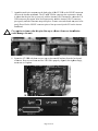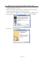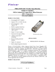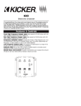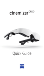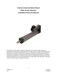
1
LT--USB
B
USB 2.0 LSL
LOT
T Intterfaace
Usser Man
M nual
Lynx Stu
udio Techn
nology, Incc.
www.lynxxstudio.com
m
[email protected]
m
Page 1 of 45
User Manual
Table of
o Contentts
1
Intro
oduction .......................................................................................................................3
1.1
Overv
view ..........................................................................................................3
1.2
Featurres ............................................................................................................4
ore you begiin ...............................................................................................................5
2 Befo
2.1
In the box .........................................................................................................5
2.2
Operaational requirrements .................................................................................5
menclature Used
U
in this manual ................................................................................7
3 Nom
4 Warrranty Regisstration .....................................................................................................7
5 Insta
allation Pro
ocedures ....................................................................................................8
5.1
Clock
k Settings and Connectio
ons ...................................................................11
Installling the Driv
ver and Auro
ora Remote C
Control Appplication ..................12
5.2
6 Gettting Started ...............................................................................................................16
6.1
Windo
ows Quick Audio
A
Test...........................................................................16
6.2
Macin
ntosh Quick Audio Test ....................
.
....................................................19
7 Auro
ora Remotee Control Ap
pplication Reference
R
........................................................22
7.1
Startin
ng the Aurorra Remote Control
C
Appllication withhin Windowss...........22
7.2
Startin
ng the Aurorra Remote Control
C
Appllication withhin OS X ..................22
7.3
Generral Operation
n ..........................................................................................22
8 Usin
ng the LT-U
USB ..........................................................................................................31
8.1
8/16 Channel
C
Mod
des ......................................................................................31
Use with
w USB 1.0
0, USB 2.0 and
a USB 3.0 systems .....................................31
8.2
Choossing a USB Port
P .....................................................................................31
8.3
8.4
Application Setup
p...........................................................................................33
8.5
Updatting Firmwaare ........................................................................................39
ubleshooting
g..............................................................................................................40
9 Trou
10
Su
upport..........................................................................................................................43
10.1
Lynx Website Sup
pport Resourrces .................................................................43
hone Supporrt .........................................................................................43
10.2
Teleph
Registtering your LT-USB
L
..............................................................................43
10.3
Return
n Policy .................................................................................................44
10.4
10.5
Locating the Seriaal Number of
o Your LT-U
USB ............................................44
11
Liccense Agreeement ......................................................................................................44
12
Warranty Infformation................................................................................................45
Page 2 of 45
1
Introduction
Thank you for purchasing the LT-USB™! We are proud to provide you with a reliable,
professional-quality product for your digital audio requirements.
This manual covers operation, product characteristics, and information to help you get
started. Additional information is available via our website’s support resources. Please refer
to Section 10, Support, at the end of this manual for support contact information.
The LT-USB is an LSLOT expansion interface that is designed to allow the Aurora
professional audio AD/DA converters to be used with USB 2.0 equipped laptop and desktop
computers. The LT-USB can be used with Windows or Mac based systems, with a
convenient and easy-to-use software interface for setting parameters, managing volume
levels, viewing real-time meters, etc. Up to 16 channels of simultaneous I/O are possible with
an Aurora 16, and 8 channels with an Aurora 8.
From laptops, to the most powerful servers, USB ports are found on nearly every computer
system in production. For the first time ever, Aurora converters can be used with virtually
any computer.
1.1
Overview
The Aurora/LT-USB turns your computer into a powerful digital audio workstation,
providing up to 16 total channels of mastering quality analog inputs and outputs at sampling
rates up to 96 kHz, and up to 8 channels at 176.4 kHz or 192 kHz. The included remote
control application provides zero-latency monitoring, accurate metering, adapter
configuration and flexible routing capabilities. With support for WDM and ASIO on
Windows computers and Core Audio with OS X Macintosh computers, virtually all
professional audio applications can work with the LT-USB.
The LT-USB features a USB 2.0 Device port (Type B) which is typically connected to a
computer via a standard high-speed USB 2.0 cable (provided). Installation of the LT-USB
into an Aurora is straightforward, as is the driver installation routine (Please note that driver
installation is not required for OS X – native support is provided by the operating system).
The Aurora Remote Control application allows control and status of hardware parameters
such as Sample Rate, Clock Source, Trim levels, and routing. On Windows systems, an
independent LT-USB control applet provides access to other important parameters such as
buffer size, device settings and status.
The LT-USB was designed with adaptability in mind. The hardware can be field
programmed through simple firmware updates which can be downloaded from the Lynx
Studio Technology website. In this way, the product’s functionality and feature-set can be
easily upgraded by the end-user.
Page 3 of 45
1.2
Features
¾ USB 2.0 Device port (Type B)
¾ USB Audio Class 2.0 compliant
¾ With an Aurora 16, provides 16 channels of I/O at sample rates up to 96 kHz and 8
channels at up to 176.4/192 kHz
¾ With an Aurora 8, provides 8 channels of I/O at all sample rates
¾ Supports routing of USB audio streams to Aurora’s AES/EBU outputs
¾ Works with almost any USB 2.0-equipped computer
¾ Supports ASIO and WDM for Windows and CoreAudio for Mac OS X
¾ Fully supports current operating systems, Windows 7 and OS X 10.6.4+, as well as
Windows XP and Vista
¾ All relevant settings, such as sample rate selection, sync source selection, channel
routing, latency, and buffer size are enabled, controlled and monitored from the host
computer
¾ Full WDM and Core Audio implementation allows multiple channel support of 5.1 and
7.1 surround playback formats
¾ Easily installed into Aurora
¾ Supports external clocking with Windows and OS X
¾ Field programmable
¾ Ideal for fixed location or mobile recording applications
Page 4 of 45
2
Before you begin
We recommend that you read through the entire manual to acquire an overview of the
installation procedure and use of the LT-USB. This manual will presume a working
knowledge of the Aurora converter. For additional information, please refer to the Aurora
User Manual.
It is also highly recommended that you have a good working knowledge of Windows and/or
Macintosh operating system basics and an understanding of computer hardware basics. This
information is widely available on the web and from various computer hardware and
software manufacturers.
We also strongly recommend you familiarize yourself with the basics of digital audio and
computer recording, and particularly with the basic functionality of your chosen audio
software. A solid grasp of the operational fundamentals of your Digital Audio Workstation
software and its user interface will go a long way toward enhancing your experience with the
LT-USB.
2.1
In the box
The following items are included in your LT-USB carton:
¾
¾
¾
¾
¾
¾
LT-USB card in an antistatic bag
One 6’ long Type-A to Type-B shielded USB 2.0 cable
Lynx Installation CD containing current drivers and this manual
Warranty registration card
Quick Start Guide
½” Standoff Post
If any items are missing or damaged, please contact your dealer or Lynx at
http://www.lynxstudio.com.
2.2
Operational requirements
There are three essential elements that must be met for compatibility with the LT-USB:
1. The host computer must have a compatible and functional USB 2.0 port.
2. The host computer must meet the system requirements necessary for correct functioning
of the LT-USB.
3. The Aurora must have firmware revision 24 or above.
It also is important to note that most professional audio applications place significant
demands on your computer’s resources, and it is therefore recommended that you meet or
exceed the recommended system requirements for your Digital Audio Workstation software,
which will likely be greater than those listed for the LT-USB. Please refer to your audio
software’s documentation for more information.
Page 5 of 45
2.2.1
¾
¾
¾
¾
¾
Windows
Intel Core 2 @ 1.6 GHz, or AMD equivalent
PC or laptop manufactured after January 2006
1GB RAM
One functional USB 2.0 port
Windows XP with SP3 (32-bit), Windows Vista with SP2 (32-bit or 64-bit) or Windows
7 (32-bit or 64-bit)
NOTE: The LT-USB is not supported under Windows 95, 98, ME or Windows 2000.
Windows installed via BootCamp is not officially supported.
2.2.2
Macintosh
¾ Any Intel Processor based Mac or MacBook computer running OS X 10.6.4 or higher
¾ 1GB RAM
¾ One functional USB 2.0 port
NOTE: The LT-USB is not supported under OS 9 or OS X 10.6.3 or below.
2.2.3
Insuring compatible firmware on the Aurora
The LT-USB requires your Aurora converter to have Firmware Version 24 or later. This
should be verified prior to installing and configuring the LT-USB card. To determine what
firmware revision your Aurora has installed, press the TRIM and POWER buttons at the
same time with the power to the Aurora off. If the LED flashes over the numbers 2 on the
input row & 4 on the output row or above (i.e. 2&5, 2&9, etc.) in the Aurora Meter Display,
then your unit is compatible with the LT-USB. If pressing Power and Trim does not cause
any LEDs to flash, causes a sequence lower than 24 to flash, or causes a single number to
flash, then your unit needs to be updated.
If your Aurora has firmware version 13 or above, it can be updated by an Apple Macintosh
running OS X or a Windows PC with a MIDI interface. The Aurora firmware updater
program and instructions for use are available for download from the Lynx website at
Support > Downloads. If your unit has rev 12 or earlier, please contact Lynx Technical
Support (U.S. or Canada) or your local distributor for firmware update options. Please note
that Auroras manufactured in 2006 or later should have firmware revision 13 or above.
Page 6 of 45
3
Nomenclature Used in this manual
The following typographic conventions are used in this manual:
¾ ALL UPPER CASE TEXT refers to a specific parameter selection control (i.e. SYNC
SOURCE) or a cable connection.
¾ Text in quotation marks indicates a parameter selection value or menu option (i.e.
“EXT”).
Phrases, such as: Start > Programs > Lynx Studio Technology use the greater than symbol
(“>”) to indicate multiple menu options or mouse selections within a software control
context.
4
Warranty Registration
Lynx is committed to providing you with the best service possible. To help us serve you
better, please be sure to register your LT-USB using one of the following methods:
Fill out and mail the Warranty Registration Card included with your LT-USB.
Register on the web at: www.lynxstudio.com > Support> Register Your Product
Once you are registered you will automatically receive notifications of new products and
upgrades.
Page 7 of 45
5
Insttallation Procedures
P
s
Please in
nsure that thee Aurora has firmware 24
2 or above before proceeeding. See Section 2.2.33
1. Remo
ove the AC power
p
cord and
a take the top cover offf of the Aurrora. There aare seven
large screws pluss one small screw
s
near th
he center of tthe front facceplate that hholds the topp
coverr on.
2. Beforre installing the LT-USB
B card, you must
m changee a dipswitchh setting on tthe Aurora
that corrects
c
the current
c
draw
w for an Auro
ora with an L
LT-USB
Slide switch 4 (laabeled W4 on PCB) of SW1
S
to the O
OFF positionn (towards baack panel).
If you
u are updatin
ng an older Aurora
A
that has
h jumper ppins at JP6, iinstead of thhe W4
switcches, please call
c Lynx Teechnical Sup
pport for insttructions.
3. Remo
ove the LSL
LOT Expansiion Port coveer above thee AES I/O Poorts by remooving the twoo
moun
nting screws. Set these tw
wo screws aside, as theyy will be usedd to secure tthe LT-USB
after installation.
Page 8 of 45
4. Remo
ove the screw
w from the Aurora
A
circu
uit board thatt is adjacent to the JP1 connector andd
the white
w
serial number/barco
n
ode label. Seet the screw aside for reuuse.
5. Installl the standoff post (inclu
uded with th
he LT-USB) in this samee hole.
6. Grou
unding yourself to earth ground,
g
remo
ove the LT-U
USB from itts protective anti-static
bag.
Page 9 of 45
7. Attacch the multi-pin connecto
or on the bacck edge of thhe LT-USB to the LSLO
OT connectorr
(JP1)) on the Auro
ora mainboaard. The LT-U
USB LSLOT
T connector has a protecctive sheath
to inssure that the pins line up correctly with
w the Auroora LSLOT cconnector. W
When the LT
TUSB connector pins
p appear to
o be lined up
p correctly w
with the Auroora LSLOT connector,
press gently untill the connecttor snaps into place. In ssome cases, tthe board maay need to be
gently
y flexed for the LSLOT connector pins
p to line uup correctly w
with JP1 on the Aurora
mainb
board.
Use cau
ution to inssure that the
t pins lin
ne up as sh
hown. Incoorrect instaallation
could damage
d
thee unit.
8. Securre the LT-US
SB with threee screws; on
ne on the staandoff and tw
wo from the back panel
of Au
urora. Keep screws loosee until the LT
T-USB is prroperly alignned, then tighhten snugly,
but do
d not over tiighten.
Paage 10 of 45
9. Reinstall the Aurora lid using the eight screws that had been removed in step 1. Do not
over tighten the small screw near the center of the front faceplate as it is easily damaged.
10. Plug in and power up the Aurora using the front panel standby switch. You can see the
LT-USB from the slits in the Aurora top cover. If the green LED on the LT-USB lights
up, the installation was successful. If the LED does not light, unplug the Aurora and remount the LT-USB, making sure that it is securely attached. Then plug in and power up
again. If the green LED still does not light, please contact Lynx Customer Support.
5.1
Clock Settings and Connections
Please see Section 2.6 Clock Settings and Connections, of the Aurora User Manual for
information about correct clocking of the Aurora within a digital audio system. When used
with an LT-USB, the SYNC SOURCE can only be from changed from the front panel of the
Aurora while the USB cable is disconnected. After the SYNC SOURCE is selected and
Synchrolock has achieved full lock, reconnect the USB cable. When the USB connection is
active, the Aurora will enter a lock-out mode, where some parameters such as SYNC
SOURCE/SAMPLE RATE cannot be altered from either the front panel or Remote Control
software.
5.1.1
Using the Internal Clock
We recommend using Internal as the SYNC SOURCE for the best clock performance.
In this state, the Aurora can respond to sample rate changes from audio software, but not all
applications will send these rate change requests.
In all compatible versions of Windows, ASIO applications will generally request sample rate
changes to follow the project sample rate, or the rate of the audio being played.
In Windows XP, applications using the WDM/DirectSound or MME/Wave Out driver
models will also typically request a sample rate change of the driver to match the project or
audio file rate.
In Windows Vista and Windows 7, WDM/DirectSound and WASAPI applications do NOT
typically request sample rate changes. Instead they rely upon Sample Rate conversion built
into the operating system to convert the play rate to the rate of the audio hardware. If one
wishes to avoid the effects of this rate conversion, the sample rate can be changed globally
from the Sound section of Windows control panel (Sound > Properties > Advanced). After
changing the sample rate, the play application often will need to be restarted.
In OS X, some Core Audio applications will initiate a change of sample rate to match the
project or audio file being played, and others will not. For the most part, professional audio
recording software does request sample rate changes, and consumer or media playback
software does not. Examples of the former would be Logic, ProTools, Cubase, Digital
Performer, etc. Examples of the latter would be iTunes, DVD playback software or
Quicktime.
Page 11 of 45
When the application does not request a sample rate change, and one wishes to avoid sample
rate conversion, the sample rate can be changed from within Audio MIDI setup in OS X to
match the desired sample rate. After changing the sample rate, the play application often will
need to be restarted.
5.1.2
Using External / AES A / AES B Clock
The Aurora can slave to a master/house clock source via Word clock or via its AES inputs. In
this state, it is also important to verify that the clock source is operating at the same sample
rate as the audio being played, no matter what driver model is being used by the LT-USB.
See the Aurora manual for more information about these SYNC SOURCE choices.
If you wish to use the Lynx Synchrolock technology while clocking externally, it is crucial to
ensure Synchrolock has fully engaged before connecting the USB cable to the host computer.
Synchrolock engaging while the USB bus is active could cause loud, highly distorted signal.
5.1.3
Using LSLOT Clock
When an LT-USB equipped Aurora is used with a computer, it is possible to have the Aurora
slave to the clock generated by the USB interface. This would be the case when LSLOT is
selected as the SYNC SOURCE. As a general rule, we do not recommend this clocking
scheme. The clock signal derived from a USB device can be very inaccurate. Although
SynchroLock is capable of regenerating poor quality clock sources, there may be cases where
the USB-generated clock can fall outside of Synchrolock’s usable range, and the Aurora
sound quality will be adversely affected.
5.2
Installing the Driver and Aurora Remote Control Application
The Lynx Installation CD contains all driver files and utilities mentioned in the subsequent
installation steps, as well as the LT-USB manual, driver release notes and test files. If you do
not have a CD-ROM drive or need a more recent version, these files are available on our
website at http://www.lynxstudio.com/ > Support
If you have downloaded more recent drivers than those included on your Lynx Installation
CD, the following instructions can still be followed. Launch the driver install file from the
download rather than from the CD. If a previous driver version is present, it will
automatically be removed as part of the driver installation process. Note: no driver
installation is required for OS X, only for Windows.
Page 12 of 45
5.2.1 Windows
W
XP
P, Vista (32--bit or 64-biit), or Wind
dows 7 (32-b
bit or 64-bitt)
1. Poweer on the Aurrora with thee USB cablee disconnecteed. From thee front panell, set the TO
ANA
ALOG OUT button
b
to “L
LSLOT IN”.
2. The LT-USB
L
driv
ver should be
b installed prior
p
to connnecting the A
Aurora to the computer.
Insertt the Lynx In
nstallation CD
C into yourr computer’ss disk drive.
3. Locatte the Windo
ows\LT-USB
B folder on the
t CD. Douuble-click thhe LTUSBSeetup.exe filee.
4. When
n prompted, accept the default
d
destin
nation folderr of C:\Lynxx and click “IInstall”.
5. Click
k “Next >” on the welcom
me screen
Paage 13 of 45
6. The system
s
will search
s
for th
he LT-USB and
a should bbe unable to find it. Connnect the LTUSB and click “N
Next>”
6. Accept the default destination
n folder for the
t driver filles and clickk “Install>”
7. Afterr installation has completed, click “N
Next >”
Paage 14 of 45
8. Click
k “Finish >”.
9. You may
m receive a warning that
t the driveer has not beeen digitally signed by M
Microsoft. It
is saffe to disregarrd this warniing and selecct “Continuee Anyway.”
10. On so
ome systemss the Window
ws hardwaree wizard willl launch post driver instaallation. In
this case,
c
run the wizard usin
ng the “Autom
matic Installlation” optioon, acceptingg the defaults,
until it completess. Skipping this
t step may
y cause the ddriver to funcction incorreectly.
11. When
n the installaation is finish
hed, you can
n launch the Aurora Rem
mote Controll applicationn
from Start > All Programs
P
> Lynx Studio
o Technologyy. For moree informationn, see
Section 7, Auroraa Remote Co
ontrol Appliccation Referrence.
5.2.2 OS
O X
1. The LT-USB
L
usees the built-in
n USB 2.0 au
udio class drriver provided in OS X 10.6.4 and
up. No
N additionaal driver installation is reequired. Pow
wer on the Auurora with thhe USB cablle
disco
onnected. Fro
om the front panel, set th
he TO ANAL
LOG OUT pparameters to “LSLOT”.
2. Simp
ply connect th
he appropriaate USB cable from the A
Aurora to thhe computer’’s USB 2.0
port. The Aurora driver devicces will imm
mediately beccome availabble to Core A
Audio
applications.
3. To in
nstall the Aurrora Remotee Control app
plication, loccate the OS X/LT-USB folder on thee
CD. Double-clicck the AuroraaRemoteInsttaller.pkg fille. For more informationn, see Sectionn
urora Remotee Control Ap
pplication Reference.
R
7, Au
Paage 15 of 45
6
Gettting Startted
With the LT-USB drrivers and Au
urora Remotte Control appplication innstalled, the A
Aurora can
now be used
u
with mo
ost popular th
hird-party au
udio applicaations. Howeever, it is a ggood practicee
to verify that the insttallation wass successful and
a test the A
Aurora withh the followinng
procedurre.
6.1
Wiindows Quick Audio Test
The instaallation of yo
our LT-USB
B can be testeed using the Aurora Rem
mote Controll applicationn
and the Lynx
L
Demo application
a
included
i
on the Lynx Insstallation CD
D. This is a qquick way of
verifying
g that the inteerface is insttalled correcctly and propperly conneccted to your eexternal
equipmen
nt.
1. Conn
nect the Anallog Outputs of the Aurorra to monitooring equipm
ment capable of deliverinng
an au
udio signal fo
or listening via
v headphon
nes or speakkers. Dependding on yourr external
equip
pment, you may
m be using
g the Lynx CBL-AOUT8
C
85 or a thirdd party equivvalent. Verifyy
that Analog
A
Outs 1 & 2 of thee Aurora aree connected tto your exterrnal equipm
ment. These
are th
he outputs ussed for this test.
t
2. For th
his test we will
w set the Aurora
A
on Intternal as the clock source. This is thee default
state of the Aurorra. If this has been altereed, disconnecct the USB ccable and select INT
from the Aurora front
f
panel and
a then reco
onnect the U
USB cable.
3. On th
he Digital I/O
O and Settin
ngs page of th
he ARC, verrify that TO ANALOG O
OUT is set too
“LSL
LOT IN”.
4. Open
n the Lynx Demo
D
applicaation by clicking Start > All Program
ms > Lynx S
Studio
Techn
nology > Ly
ynx Demo, or
o locate Win
ndows/Demoo32.exe on th
the Lynx Installation CD
D
and double-click
d
to run it. Th
he Lynx Dem
mo program should appeear in the uppper left
corneer of your screen. Make certain that the
t Play Devvice is set too Lynx LT-U
USB/Aurora
5. Locatte “SineWav
veMinus16.w
wav” in the support
s
foldeer of the Lynnx Installatioon CD. Dragg
the fiile to the com
mputer’s dessktop.
6. In Ly
ynx Demo, click “File” and
a navigate to the compputer’s Deskktop, then sellect
“SineeWaveMinuss16.wav” an
nd click “Opeen.”
7. Click
k “Play.” You should seee the progresss bar move from left to right.
Paage 16 of 45
8. Laun
nch the Aurorra Remote Control
C
appliication. Clickk the Analogg I/O tab. Chheck for
meterr activity forr Analog Ou
utputs 1&2. If
I you have sspeakers or hheadphones connected too
your destination device,
d
you should be heearing audioo as well.
If the tesst did not op
perate as deescribed or you
y received
d any errorrs, please refer to
Section 10,
1
Paage 17 of 45
Troubleshooting.
Page 18 of 45
6.2
Ma
acintosh Qu
uick Audio Test
T
The instaallation of yo
our LT-USB
B can be testeed using the Aurora Rem
mote Controll applicationn
and the iT
Tunes softw
ware that is in
ncluded with
h OS X. Thiss is a quick w
way of verifyying that thee
interface is installed correctly and properly connected
c
to your externnal equipmennt.
1. Open
n Audio MID
DI Setup from
m Applicatio
ons > Utilitiees.
2. If thee Audio Devices window
w does not ap
ppear autom
matically, thenn select “Shoow Audio
Menu
u” from the “Window”
“
menu.
m
3. All av
vailable aud
dio devices will
w appear in
n the left panne. Locate thhe Lynx LT--USB from
this liist.
4. Selecct this devicee. From the Gear
G icon in the bottom left corner, cclick “Use thhis device foor
sound
d output”
5. Locatte “SineWav
veMinus16.aaif” in the “ssupport” foldder of the Lyynx Installatiion CD. Draag
the fiile to the com
mputer’s dessktop.
6. Conn
nect the Anallog Outputs of the Aurorra to monitooring equipm
ment capable of deliverinng
an au
udio signal fo
or listening via
v headphon
nes or speakkers. Dependding on yourr external
equip
pment, you may
m be using
g the Lynx CBL-AOUT8
C
85 or a thirdd party equivvalent. Verifyy
that Analog
A
Outs 1 & 2 from the Aurora are connecteed to your exxternal equippment. These
are th
he outputs ussed for this test.
t
Paage 19 of 45
7. For th
his test we will
w set the Aurora
A
to Inteernal as the cclock sourcee. This is thee default statte
of thee Aurora. If this has been
n altered, dissconnect thee USB cable and select IN
NT from thee
Aurora front paneel and then reconnect
r
thee USB cablee.
8. Laun
nch iTunes frrom “Applications” or frrom the OS X dock. Draag the
“SineeWaveMinuss16.aif” file from your desktop
d
into the iTunes ssonglist
9. Highlight this filee from the so
onglist and click
c
the Playy button. Maake sure thatt the iTunes
m
from left to right.
progrress bar is moving
10. Open
n the Lynx Aurora
A
Remo
ote Control application.
a
C
Click the Annalog I/O tabb. Check for
meter acttivity for An
nalog Outputts 1&2. If yo
ou have speaakers or headdphones connnected to
your desttination deviice, you shou
uld be hearin
ng audio as w
well.
If the tesst did not op
perate as deescribed or you
y received
d any errorrs, please refer to
Section 10,
1
Paage 20 of 45
Troubleshooting.
Page 21 of 45
7
Aurora Remote Control Application Reference
The Aurora Remote Control (ARC) application allows control of Aurora parameters from a
convenient software interface. It also provides accurate real-time metering for all inputs and
outputs, and displays status information such as channel mode, sync source and sample rate.
The ARC is automatically installed with the Windows driver setup program, and is a separate
install under OS X (see Section 5.2, Installing the Driver and Aurora Remote Control
Application).
7.1
Starting the Aurora Remote Control Application within Windows
Make sure that the Aurora is powered up, and that the Aurora is connected to the computer
by a USB cable. From the Start Menu, click Start > Programs > Lynx Studio Technology >
Aurora Remote Control.
7.2
Starting the Aurora Remote Control Application within OS X
Make sure that the Aurora is powered up, and that the Aurora is connected to the computer
by a USB cable. From Finder, click Applications >Aurora.
7.3
General Operation
The Aurora Remote Control Application allows the user to control output levels, route inputs
to outputs, alter various parameters, and view accurate meters for inputs and outputs on a
connected Aurora. Most parameter changes will be reflected both on the Aurora front panel
and within the software application.
Some parameters can be established identically from the software or front panel. Other
parameters have extended functionality through the software, particularly routing functions
and setting trim levels. When these functions are modified in the software, the Aurora front
panel will indicate this by illuminating all the LEDs for that function. For instance, the front
panel choices for the button labeled TO ANALOG OUT and TO DIGITAL OUT are
“ANALOG IN”, “AES IN” and “LSLOT IN”. When selecting a choice from the front panel,
the LED will be illuminated for the active selection. If custom routing is established in the
software, all three LEDs will illuminate.
Page 22 of 45
When thee Aurora Remote Contro
ol application
n is run via tthe LT-USB
B connectionn, the Auroraa
will enterr a “lock-outt” mode wheere some fro
ont panel conntrols will bee disabled, aand control iss
restricted
d to the ARC
C software orr from settin
ngs within thhe operating system. Thee following
table detaails which frront panel fu
unctions are impacted
i
byy “lock out” mode:
q
SAMPLE RATE
This button will not
n be activee. The curren
nt operating sample rate will be indiccated by thee
corresponding LE
ED. Sample rate can only
y be set from
m within the host audio aapplication
and/o
or an operatin
ng system so
ound settings page.
w
SYNC
C SOURCE
This button will not
n be activee. The LED for
f the sync source, which has been selected
prior to the conneection of thee USB cable,, will illuminnate.
If no clock signall is availablee for the SYN
NC SOURCEE selected, thhe LED for thhe selected
sourcce will flash,, and the Aurrora will opeerate from itts internal cloock.
e
SynchroLock
unction norm
mally. See thee Aurora maanual a descrription of SyynchroLock.
This LED will fu
The SynchroLock
S
k status musst be established prior to the connecttion of the U
USB cable.
r
TO ANALOG
A
OU
UT
This button will not
n be activee. For operattion with thee LT-USB, either LSLOT
T IN or
Remo
ote Routing mode with LSLOT
L
sourrces assignedd should be sselected withh the ARC
application. LSL
LOT IN routees play streaams from thee computer, vvia the USB
B port, to the
m within the A
ARC
Aurora’s Analog outputs. If any custom routing is innitiated from
hree LEDs will
w be illumiinated, indic ating that thhis parameterr is being
application, all th
contrrolled remoteely.
t
TO DIGITAL
D
OUT
T
This button will not
n be activee. For operattion with thee LT-USB, R
Remote Routting mode
with LSLOT sourrces assigned should be selected witth the ARC aapplication. If any
om routing iss initiated fro
om within th
he ARC appllication, all tthree LEDs w
will be
custo
illum
minated, indiccating that th
his parameteer is being coontrolled rem
motely.
y
IR/MIDI
This LED will fu
unction norm
mally. See thee Aurora maanual for infoormation.
u
Peak Meters
Thesee LEDs will function normally. See the Aurora m
manual for iinformation.
i
IR Trransceiver
This will function
n normally. See the Auro
ora manual ffor information.
Paage 23 of 45
o
METER
This button will function normally. See the Aurora manual for information.
a
TRIM/AES MODE
When the METER select switch is set to “Analog”, this button normally allows the
nominal trim level to be set for the analog inputs and outputs. In “Lock Out” mode, this
button will not be active, and trims can be set for the Analog inputs and outputs from
within the Aurora Remote Control application. If the trim value for any analog I/O is
altered from within the software, both the +4 dBu and –10 dBV LEDs will be
illuminated, indicating that this parameter is being controlled remotely.
When the METER select is set to “Digital”, this control allows configuration of the
AES/EBU digital I/O. In “Lock Out” mode, the button will not be active, but the LEDs
will reflect the dual-wire state for the digital inputs and outputs.
s
POWER
This button will function normally. See the Aurora manual for information.
Page 24 of 45
7.3.1 Analog
A
I/O Page
P
This pagee is viewablee by clicking
g the “Analo
og I/O” Tab in the top leeft corner of the Aurora
Remote Control
C
appllication.
q
These
T
indicattors will illum
minate when
n three conseecutive full-sscale samplees are
detected on th
he Aurora Analog
A
Inputss and Outputts or when a summing overrun
occurs on the Aurora Anaalog Outputss. The indicaator will rem
main illuminaated for
250ms.
w
These
T
meters display the instantaneou
us peak leveel of audio beeing sent to the Aurora
Analog
A
Inputs and Outpu
uts.
e
These
T
buttonss allow the Analog
A
inputt or output trrims to be seet. Each buttton allows
grroups of fou
urs channels to be toggled between +
+4dBu (the ddefault) and --10dBV.
r
These
T
tabs alllow monitorr source grou
ups to be seleected for thee Analog Ouutputs when
Remote
R
Routing is utilizeed. The Auro
ora can be seet for global routing (i.e.. AES In
ro
outes to Anaalog Out) or Remote Rou
uting. With R
Remote Rouuting up to tw
wo sources
(S
Source A and Source B) can be estab
blished for eeach output. Analog Outpputs 1-4 havve
16 additional monitor sou
urces (Sources C – R), w
which can bee accessed froom the
Output
O
1-4 taabs. For thesee custom mo
onitor sourcees to be activve, the TO A
ANALOG
OUT
O
switch on
o the Digitaal I/O & Setttings page m
must be set too “Remote”. In this state
alll three LED
Ds for the TO
O ANALOG OUT buttonn on the Aurrora front pannel will be
illluminated.
t
These
T
buttonss allow indiv
vidual monittor sources too be selectedd for each annalog outputt
when
w
using Remote
R
Routting. Clickin
ng a button alllows selectiion of any A
Analog,
Digital
D
or LSL
LOT input source.
s
Hold
ding down thhe CTRL keyy while seleccting a sourcce
Paage 25 of 45
caauses the rem
maining chan
nnels to be set
s sequentiaally (i.e. if yoou select LS
SLOT In 1 ass
th
he monitor source for An
nalog Out 1 while holdinng down the CTRL key, LSLOT In
1-16 will be assigned
a
to Analog
A
Out 1-16).
Please
P
note th
hat with an LT-USB
L
insttalled, LSLO
OT sources coorrespond too audio
sttreams coming from the host computter.
y
These
T
faders allow contro
ol over the output
o
level oof each moniitor source w
when in
Remote
R
Routing mode. This
T level atteenuation occcurs in the ddigital domaiin, so it is
reecommended
d to leave these faders in
n their defauult, maximum
m position inn situations
where
w
the hig
ghest fidelity
y is required.. Holding doown the SHIIFT key on tthe keyboardd
while
w
adjustin
ng a fader, will
w cause adj
djustment of channel pairrs.
u
i
This
T display reveals
r
the amount
a
of atttenuation, inn dB, of a moonitor source.
This
T button en
nables the mute
m function
n for the assoociated monnitor source.
Settings
This
T display reveals
r
the trrim, power up,
u and curreent channel m
mode settingg of the
Aurora.
A
When
W
TRIM ORIGIN is set to “Remo
ote”, the Auurora trim levvels are set oon a 4ch
hannel per group
g
basis controllable
c
from
f
the AR
RC. When seet to “Local””, the trims
fo
ollow the value displayed in LOCAL
L TRIM, whhich is controollable from the front
panel TRIM button.
b
When
W
POWE
ER UP MOD
DE is set to “Standby”, thhe Aurora caan only comee out of
sttandby modee by pressing
g the black standby
s
buttoon on the Auurora front ppanel. When
seet to “On”, applying
a
pow
wer to the AC
C input of thhe Aurora wiill immediattely power oon
th
he Aurora, th
hereby bypasssing standb
by mode. Thiis control caan be toggledd by holdingg
down the blacck standby button
b
as AC
C power is appplied.
Paage 26 of 45
Digital I/O & Settin
ngs Page
This pagee is viewablee by clicking
g the “Digitaal I/O & Setttings” Tab inn the top left
ft corner of
the Aurora Remote Control
C
appliication.
o
These
T
indicattors will illum
minate when
n three conseecutive full-sscale samplees are
detected on th
he Aurora Digital Inputss and Outputts or when a summing ovverrun occurrs
n the Auroraa Digital Outtputs. The in
ndicator willl remain illum
minated for 250ms.
on
a
These
T
meters display the instantaneou
us peak leveel of audio beeing sent to the Aurora
Digital
D
Inputss and Outputts.
s
These
T
tabs alllow monitorr source grou
ups to be seleected for thee Digital Outtputs when
Remote
R
Routing is utilizeed. The Auro
ora can be seet for global routing (i.e.. AES In
ro
outes to Anaalog Out) or Remote Rou
uting. With R
Remote Rouuting up to tw
wo sources
(S
Source A and Source B) can be estab
blished for eeach output. For these soources to be
acctive, the TO
O DIGITAL OUT switch
h on the Diggital I/O & Settings pagee must be sett
to
o “Remote”. In this statee all three LE
EDs for the TO DIGITA
AL OUT buttton on the
Aurora
A
front panel
p
will bee illuminated
d.
d
These
T
buttonss allow indiv
vidual monittor sources too be selectedd for each diigital output
when
w
using Remote
R
Routting. Clickin
ng a button alllows selectiion of any A
Analog,
Digital
D
or LSL
LOT input source.
s
Hold
ding down thhe CTRL keyy while seleccting a sourcce
caauses the rem
maining chan
nnels to be set
s sequentiaally (i.e. if yoou select LS
SLOT In 1 ass
th
he monitor source for Diigital Out 1 while
w
holdinng down the CTRL key, LSLOT In 1116 will be asssigned to Dig
gital Out 1-1
16).
Please
P
note th
hat with an LT-USB
L
insttalled, LSLO
OT sources coorrespond too USB audioo
sttreams coming from the host computter. By defauult these auddio streams aare deliveredd
Paage 27 of 45
to the Analog Outputs. By manually assigning LSLOT sources to the Digital Outputs,
these signals can be mirrored to the Aurora AES/EBU outputs as well.
For example, to send USB audio streams to the digital outputs, assign LSLOT 1-16
(for an Aurora 8, assign LSLOT 1-8) to the digital outputs as “SOURCE A” and set
“TO DIGITAL OUT” to “REMOTE”.
f
These faders allow control over the output level of each monitor source when in
Remote Routing mode. This level attenuation occurs in the digital domain, so it is
recommended to leave these faders in their default, maximum position in situations
where the highest fidelity is required. Holding down the SHIFT key on the keyboard
while adjusting a fader, will allow adjustment of channel pairs.
g
h
j
This display reveals the amount of attenuation, in dB, of a monitor source.
k
This button enables the mute function for the associated monitor source.
This display indicates the status of the digital inputs. If a valid digital signal is present
the display will indicate “Locked”. If a valid digital signal is not present the display
will indicate “Unlock”.
This drop-down menu allows for selection of the clock source that drives the Aurora
sample clock generator from the following options:
INT
Clock derived from the on-board crystal oscillator.
EXT
Clock signal from WORD CLOCK input.
EXT/2
Clock signal from WORD CLOCK input running at half the desired
sample rate. Typically used with dual-wire AES/EBU devices.
AES A
Clock signal from the AES I/O Port A Digital Input. Clock is derived
from the first valid AES/EBU channel.
Aurora 8 Clock signal from the AES inputs 1-4.
AES B
Clock signal from the AES I/O Port B Digital Input. Clock is derived
from the first valid AES/EBU channel.
Aurora 8 Clock signal from the AES inputs 5-8.
LSLOT
Clock Signal from the computer’s USB adapter. Under normal
circumstances, this is NOT a recommended clock source.
Please note that when the LT-USB is connected to the computer and active, the SYNC
SOURCE cannot be controlled through the Aurora Remote Control software. The
SYNC SOURCE must be established from the front panel before connecting the USB
cable.
l
This drop-down menu normally allows for selection of the sample rate for the Aurora
when set to “INTERNAL”, however when using an LT-USB, the SAMPLE RATE
drop-down menu is only used to display the active sample rate. The desired rate
should always be established from within the host audio software or the OS’s audio
settings section (ie. Windows Sound Control Panel or OSX Audio Midi Setup). Even
if the Aurora is slaving to an external clock master, the sample rate selected within
the DAW and/or OS default should match the rate generated by the clock source. For
more information, see Section 5.1, Clock Settings and Connections.
Page 28 of 45
;
This
T drop-dow
wn menu alllows for seleection of the signal sourcce that will bbe routed to
th
he analog ou
utputs. “ANA
ALOG IN”, “AES IN” aand “LSLOT
T IN” are gloobal
seelections, aff
ffecting all an
nalog outputt channels. ““LSLOT” rouutes signals from the
co
omputer via the USB connection. Ch
hoosing “RE
EMOTE” alllows individu
dual sources
to
o be assigned
d from the Monitor
M
Sourrce section oon the ANAL
LOG I/O Pagge of the
Aurora
A
Remo
ote Control application.
a
2)
This
T drop-dow
wn menu alllows for seleection of the signal sourcce that will bbe routed to
th
he digital outtputs. “ANA
ALOG IN”, “AES IN” aand “LSLOT
T In” are globbal
seelections, aff
ffecting all an
nalog outputt channels. C
Choosing “R
REMOTE” alllows
in
ndividual sou
urces to be assigned
a
from
m the Monittor Source seection of the DIGITAL
I//O Page of th
he Aurora Remote
R
Contrrol applicatioon. With an LT-USB, thhe “LSLOT
IN
N” selection does not rou
ute signals from
f
the com
mputer via thhe USB connnection. To
asssign USB audio
a
sources to the digittal outputs, cchoose “REM
MOTE” andd manually
asssign the LS
SLOT sourcees.
2!
This
T parameteer is not perttinent for thee LT-USB aand should bee left on the default statee
of “DIGITAL
L OUT”.
2@
This
T drop-dow
wn menu determines wh
hether the Auurora front ppanel meters display
acctivity for th
he digital or analog
a
inputts and outpuuts.
2#
This
T checkbo
ox activates dual-wire
d
mo
ode for the A
AES inputs. See the Aurrora User
Manual
M
for in
nformation.
2$
This
T checkbo
ox activates dual-wire
d
mo
ode for the A
AES outputss. See the Auurora User
Manual
M
for in
nformation.
2%
This
T checkbo
ox activates the
t SynchroL
Lock clockinng system. S
See the Auroora User
Manual
M
for in
nformation.
2^
This
T display shows
s
the status of the SynchroLock
S
k clocking syystem. See thhe Aurora
User
U Manual for informattion.
7.3.2 Mixer
M
Menu
u
In the Windows version of ARC,, the
ner
“Mixer” menu in the top left corn
identifiess the connecttion medium
m for the
Aurora, and
a providess access to th
he “About
Aurora Remote..,”
R
sccreen.
In thhe OS X verrsion, the equuivalent is thhe
“Auurora” menu..
Paage 29 of 45
7.3.3 About
A
Aurorra Remote Control
C
Win
ndow
This dialog box detaiils the versio
on number of the Auroraa Remote Coontrol application, and
the hardw
ware revision
ns, serial num
mbers and board revisio ns of the Auurora and LS
SLOT
devices. It also displaays the Auro
ora’s operatin
ng temperatuure and the cconnection m
medium
being em
mployed.
Window
ws
OS X
Paage 30 of 45
8
Using the LT-USB
With the LT-USB correctly installed in your computer, you can begin to use the Aurora with
most popular third-party audio applications. In this section we will explore setting up the
Aurora/LT-USB system for different contexts of use.
8.1
8/16 Channel Modes
The LT-USB supports two channel modes: an 8-channel mode that supports sample rates up
to192 kHz and a 16-channel mode that supports sample rates up to 96 kHz. An Aurora 8 only
operates in 8-channel mode, while an Aurora 16 can operate in either mode.
The channel modes can be toggled by holding down the “TO ANALOG OUT” button on the
front panel of the Aurora for 500ms until all of the front panel LEDs flash. The USB cable
must be disconnected during this operation. The “LSLOT Channel Mode” selection can be
viewed from the Analog I/O page within the Aurora Remote Control application.
One reason to operate an Aurora 16 in 8-channel mode would be to lower the overall system
CPU usage. The fewer channels a device presents to the host computer, the lower the CPU
consumption, regardless of how many channels are actually being used for playback or
recording. Lower CPU usage can be beneficial in terms of latency performance or number of
audio plug-ins/processes that can be used in a project. For example, if playing back a stereo
file while operating in 16-channel mode at 48 kHz, the CPU consumption is equivalent to the
playback/recording of all 16-channels at 48 kHz. For this situation it would be recommended
to operate in 8-channel mode, thereby significantly lowering the CPU usage.
8.1.1
Operating at 176.4/192kHz
This feature is only available in 8-channel mode. Running the device at these rates in 16channel mode will result in distorted audio and other unpredictable behavior.
8.2
Use with USB 1.0, USB 2.0 and USB 3.0 systems
Because USB is a standard written to be backwards compatible with previous versions, all
USB 3.0 ports will be able to accept a USB 2.0 device.
USB 1.0 is currently not supported.
8.3
Choosing a USB Port
USB performance and reliability depends heavily on other traffic that shares the USB bus. In
the ideal situation the LT-USB would be the only device connected to one of the computer’s
“host controllers”. Each host controller provided by a computer acts as an independent USB
bus and allows connections for multiple devices through a “root hub”.
In Windows, to view the USB bus hierarchy, “Start> right click-My Computer> Manage>
Device Manager > View> Devices By Connection” and expand the USB Enhanced
Controller Tabs.
Page 31 of 45
ut This Macc> More Infoo…> USB” ttab:
In OS X 10.6.4+, go to the “Abou
Both of the
t following
g screenshotts show the Lynx
L
LT-US
SB as the onlly device onn a high-speeed
USB hosst controller. This is the recommende
r
ed configuraation for systtems that behhave poorly
when shaaring the US
SB bus with multiple
m
dev
vices.
Paage 32 of 45
8.4
Application Setup
The LT-USB was designed to provide maximum compatibility with the most popular audio
and multimedia applications that use the Windows MME, DirectSound, ASIO and OS X
Core Audio driver standards. It is crucial that the applications are set up correctly for optimal
operation.
8.4.1
Windows
The Windows drivers for the LT-USB support two dominant driver models, WDM (which
include both MME and DirectSound) and ASIO.
WDM was developed by Microsoft and is used most typically by media playback
applications, such as Windows Media Player, iTunes, Quicktime Player, WinDVD,
PowerDVD, etc.
ASIO was developed by Steinberg, and was designed to address the low-latency and high
channel count needs of Pro Audio and Music Production. ASIO is an option for Audio
Production applications such as Pro Tools, Cubase/Nuendo, Sonar, Samplitude/Sequoia,
Audition, etc. These applications may also support MME or DirectSound, but when the
option exists, we recommend using ASIO for the best performance.
8.4.1.1 WDM/Multimedia Applications
The Aurora/LT-USB can be used as a playback device for most popular multimedia, home
theater and consumer audio applications. Some such applications allow selection of specific
playback devices. In these cases, an Aurora output device can be selected from the
appropriate device selection menu. When output device selection is not an option, it can be
assumed that the application uses the Windows default audio device. To use the desired
Aurora output as the system default:
With Windows XP navigate to:
Start > Control Panel > Sounds and Audio Devices > Audio > Sound Playback: Default
Device = Lynx LT-USB.
With Windows Vista/Windows 7 navigate to:
Start > Control Panel > Sound > Playback. Right-Click the Lynx LT-USB output device and
choose “Set as default device”.
Since these types of programs generally use a Standard Windows driver model, the way that
the Aurora appears as a record/playback option will depend on the Channel Mode that has
been selected. In 8-channel mode, the Aurora I/O will appear as one 8-channel device. If
stereo material is played in this state, then playback will occur through the first pair of
outputs for the device selected. In 16-channel mode, the Aurora I/O will display four
additional playback devices as well as one additional record device. Each of these additional
devices corresponds to stereo pairs of channels 9-16.
Page 33 of 45
8.4.1.2 Multi-Channel Surround playback
Surround-sound material can be played and distributed to multiple outputs on the Aurora.
The playback software must have an option for decoding and playing back surround-encoded
material. The playback software should be set up to use the appropriate Aurora playback
device. In some cases, the software will use the Operating System default audio device set in
the Windows Sound control panel.
In OSX, the distribution of surround channels can be set by the user from Audio MIDI setup
> Configure Speakers > MultiChannel.
When multi-channel interleaved material is played in Windows, then the audio will be
distributed to the Aurora outputs according to the following scheme:
Channel Name
Front Left
Front Right
Front Center
Sub (LFE)
Surround Left
Surround Right
Aux Left
Aux Right
5.1 Output
1
2
3
4
5
6
N/A
N/A
7.1 Output
1
2
3
4
5
6
7
8
8.4.1.3 ASIO Applications
When using an application that supports the ASIO driver standard, one must specify the
Aurora ASIO driver as the appropriate audio device. Once that is established, multiple stereo
input and output devices will be available for use within the application. Please note: the
channel mode selected for the Aurora will determine the type and number of I/O devices
available, but within ASIO they will always be presented as multiple stereo devices, never as
8-channel devices like with WDM.
When using an ASIO compatible program, the appropriate ASIO device must be selected
from a settings or options menu in the application. The correct choice would be “ASIO Lynx
Aurora LT-USB”.
Many ASIO applications provide access to an ASIO Control Panel for the device being used.
For an LT-USB equipped Aurora, this button will launch the Lynx LT-USB Control Panel.
From this panel, the ASIO buffer size and system latency can be established conveniently
within the audio software application.
8.4.1.4 Controlling Latency by Changing the Buffer Size
Latency in an audio interface can be defined as the time required to process a sample from an
application to the interface’s audio output. A number of factors determine the achievable
Page 34 of 45
latency performance
p
of an Aurorra/LT-USB system:
s
proccessor speed,, operating ssystem,
sample raate, number of utilized record or play channels, system efficciency, etc.
Latency can
c be manipulated by changing
c
thee size of the bbuffers usedd to transfer ddata to and
from the LT-USB.
For Wind
dows, the Ly
ynx LT-USB
B control pan
nel provides access to buuffer settingss, which cann
define individual bufffer and streaam buffer sizzes for WDM
M and ASIO
O. This control panel cann
be launch
hed from eith
her the ASIO
O control setttings withinn most audioo applicationns or from
“Start> All
A Programss> Lynx Stud
dio Technology > LT-U
USB Control Panel”.
Buffer Setting
gs” tab, the Streaming
S
an
nd ASIO buuffer parametters control tthe size of
In the “B
the audio
o packets thaat are used to
o transfer aud
dio to the LT
T-USB hardw
dware. Smaller buffer
sizes willl give you lo
ower latency
y. However, if
i a buffer siize is too sm
mall for the syystem or
context, audio
a
anomaalies such ass clicks and pops
p
may occcur. It is reccommended to become
familiar with
w altering
g the LT-USB
B buffer sizee to best suitt the contextt of use.
When using ASIO baased applicattions, both th
he Streaminng and ASIO
O buffer sizess contribute
to the overall latency
y of the systeem and interaact in a cum
mulative fashiion. For insttance, a
“Streaming” buffer size of 2 ms with
w an “AS
SIO” buffer ssize of 2.2 m
ms will resultt in an overaall
one-way latency of 4.2
4 ms. It is not
n possible to set the strream buffer to be larger than the
uffer.
ASIO bu
Paage 35 of 45
When using WDM based applications, only the Streaming buffer size parameter contributes
to the overall latency of the system. The ASIO buffer size is ignored. Most WDM
applications also add a large amount of additional latency to ensure clean playback. For this
reason, ASIO is the preferred driver model for pro-audio and low-latency situations.
In order to modify the latency, the “Streaming” buffer size must first be set. Choose the
desired size and click “Apply”. Once the Streaming size is set, you will have various options
for the “ASIO” buffer size. Choose the appropriate size and click “Apply”. Once you have
determined the smallest supported Stream Buffer size, you typically will not have to change
this again. The ASIO buffer size, however, may need to be increased or lowered from time to
time depending on the context of use.
Typical values empirically found to work on modern day machines include:
o Streaming: 1 ms, Asio: 2 ms
o Streaming: 2 ms, Asio: 3 ms
o Streaming: 2 ms, Asio: 4 ms
o Streaming: 2 ms, Asio: 6 ms
If a system is not capable of supporting these values, please see the Troubleshooting section
of this manual.
8.4.2
Macintosh OS X
The Aurora will operate as a Core Audio device under OS X. Core Audio is the dominant
audio driver model for OS X, and is used for media playback applications as well as Pro
Audio applications.
8.4.2.1 OS X Audio Applications
The Aurora/LT-USB can be used as a playback device for most popular multimedia, home
theater and pro audio applications. Some such applications allow selection of specific
playback devices. In these cases, an Aurora output device can be selected from the
appropriate device selection menu.
In cases where the playback software does not provide access to output selections, the default
output devices for the operating system will be used. In OS X, the audio out default device
can be established from Applications > Utilities > Audio MIDI Setup.
Page 36 of 45
s
devicee, channels 11&2 are activve by
When thee LT-USB iss selected as the output sound
default. To
T change th
his, highlightt the LT-USB, choose “cconfigure sppeakers” from
m the gear
icon, and
d then select the desired stereo outpu
ut channels fr
from the dropp-down mennus.
C
Latency
L
by Changing
C
thee Buffer Size
8.4.2.2 Controlling
Latency in
i an audio interface
i
can
n be defined as the time rrequired to pprocess a sam
mple from ann
applicatio
on to the inteerface’s aud
dio output. A number of ffactors deterrmine the acchievable
latency performance
p
of an Aurorra/LT-USB system:
s
proccessor speed,, operating ssystem,
sample raate, number of utilized record or play channels, system efficciency, etc.
c be manipulated by changing
c
thee size of the bbuffers usedd to transfer ddata to and
Latency can
from the LT-USB. Core
C
Audio buffer
b
size co
ontrols are ooffered withiin most pro aaudio
Paage 37 of 45
recording applications. With the LT-USB, buffer sizes typically range between 32 and 2048
samples.
Smaller buffer sizes will give you lower latency. However, if a buffer size is too small for the
system or context, audio anomalies such as clicks and pops may occur. It is recommended to
become familiar with altering the LT-USB buffer size to best suit the context of use.
Once you determine the lowest achievable buffer size, you will typically have to double the
size each time you double the sample rate, but the effective latency will remain constant. For
example, if a system is capable of operating at a buffer size of 128 samples at 48 kHz, then
for a 96 kHz project, the buffer size will likely need to be increased to 256 samples.
8.4.3
Monitoring Theory
The Aurora supports hardware-based low-latency monitoring on a global or per-channel
basis. Monitoring settings can be established using the Aurora Remote Control software.
These methods avoid delays caused by monitoring through software applications.
8.4.3.1 Global Routing
Global routing can be established from the Aurora Remote Control software on the Digital
I/O & Settings Page. The choices for routing to the analog and digital outputs are “ANALOG
IN”, “AES IN”, LSLOT IN” and “REMOTE”.
Setting TO ANALOG OUT to “LSLOT IN” is the appropriate setting when the intention is
to send play streams from the computer to the Aurora, and to record audio from the Aurora
inputs into the computer.
Setting TO DIGITAL OUT to “LSLOT IN” does not route USB-audio streams to the digital
outputs. To send play streams to the digital outputs, one must route on a per-channel basis.
8.4.3.2 Remote per-channel routing
In addition to global routing, the Aurora is capable of routing individual input sources to
specific outputs, and also sending multiple sources to a single output. In order to utilize this
functionality, the source for TO ANALOG OUT and/or TO DIGITAL OUT should be set to
“Remote”.
In this mode, up to two monitor sources can be assigned to each of the Analog and Digital
outputs on the Aurora. These are defined in the ARC as Source A and Source B. The default
arrangement is for Source A to be digital in 1-16 for the Analog outputs, and Analog in 1-16
for the Digital outputs (1-8 for an Aurora 8). By default, Source B is unassigned. Any new
sources assigned must be un-muted in order to pass audio.
To send USB-audio streams to the analog or digital outputs, one must assign LSLOT In
sources to the desired output channels. In this context, it is important to remember that
LSLOT Inputs correspond directly to LT-USB play devices on the host computer. For
instance, LSLOT In 3 corresponds to the play device labeled “Analog Out 3”.
Page 38 of 45
Although LT-USB streams cannot be globally routed to the Aurora’s Digital Outputs, they
can be manually assigned to the digital outputs as “SOURCE A” or “SOURCE B” if TO
DIGITAL OUT is set to “REMOTE”.
In addition to Source A and Source B, Analog Outs 1-4 have 16 additional monitor sources
available. These provide an excellent solution for cases where, for instance, all analog inputs
need to be monitored through a stereo output. These sources, labeled C through R, are
accessed via the Output 1, Output 2, Output 3 and Output 4 tabs on the Analog I/O page of
the ARC. It is important to remember that these sources are in addition to the Source A and
Source B choices, so that analog outputs 1-4 have 18 possible monitor sources.
If one wishes to monitor all 16 analog inputs of an Aurora 16 through analog outputs 1 and 2,
this is one way to achieve that:
• Click the Output 1 tab
• Hold down the CTRL Key, while clicking the first monitor source (C). Select Analog
Input > Analog In 1. This should change all of the subsequent monitor sources in series,
resulting in Analog In 1-16 being assigned to sources C through R.
• These monitor sources are muted by default, so click the M button underneath each
channel strip to un-mute these new sources.
• Perform this same operation for output 2.
• This will send all input signals to the outputs 1 and 2 equally. If the intention is to pan
these sources within a stereo field, that can be achieved by attenuating appropriate input
sources. For instance, if input 1 should be panned hard left and input 2 panned hard right,
just mute analog input 1 from the Output 2 tab, and mute analog input 2 from the Output
1 tab. If you wish to pan input 3 75 degrees to the left, attenuate analog input 3 from the
Output 2 tab by 20dB. Sources that you wish to be located in the center of the stereo field
should be set to equal levels out of Outputs 1 and 2
8.5
Updating Firmware
The LT-USB contains firmware that is field-programmable via the USB bus. These updates
can improve performance and enhance functionality of the LT-USB. Please visit
www.lynxstudio.com for the latest firmware updates and programming instructions.
Page 39 of 45
9
Troubleshooting
There is an error message during the driver installation:
1. Verify that the LT-USB has been installed correctly and there is an LED illuminated on
the LT-USB board. See Section 5, Installation Procedures.
2. Verify that the USB cable is connected correctly and that the computer USB ports are
active and the drivers are functional.
3. Verify that your Aurora has firmware revision 24 or above
The LT-USB does not show up in the Operating System as a usable device:
1. Check that the LT-USB is correctly installed and verify that the green LED (D3) on the
LT-USB is illuminated.
2. Close the ARC and any audio applications and reset the LT-USB either by removing then
reinserting the USB cable, or by turning the Aurora off for 5 seconds, then turning it back
on.
3. Verify that the Aurora has firmware revision 24 or above. To determine what firmware
revision your Aurora has, press the TRIM and POWER buttons at the same time with the
power to the Aurora off. If the LED flashes over the numbers 2 on the input row & 5 on
the output row or above (i.e. 2&5, 2&6, etc.) in the Aurora Meter Display, then your unit
is compatible with the LT-USB. If pressing Power and Trim does not cause any LEDs to
flash, causes a sequence lower than 24 to flash, or causes a single number to flash, then
your unit needs to be updated.
4. Check that the LT-USB is connected to a compatible High-Speed USB 2.0 port.
5. Check that the LT-USB is connected via a High-Speed USB 2.0 cable (provided).
6. Check that the OS is compatible with the LT-USB. One must be running OS X 10.6.4+ or
Windows XP with SP3 (32-bit), Windows Vista with SP2 (32-bit or 64-bit) or Windows
7 (32-bit or 64-bit).
7. Remove all other USB devices from the bus and retry.
The Aurora shows up in the Operating System as a usable device, but will not pass
audio:
1. Make sure that the LT-USB has been assigned as the active device in the application
being tested. Many audio applications allow a specific audio device to be selected from a
configuration menu. Other applications will use whatever the operating system default
device is. In this case verify that the Aurora has been configured as the default playback
device for the system.
2. Check that the source for TO ANALOG OUT is set to “LSLOT IN”.
3. Check the ARC software and see if there is meter activity for the appropriate outputs
being used. If there is, check the cable connections from the Aurora analog or digital
outputs to the monitoring equipment.
4. Close the ARC and any audio applications and reset the LT-USB either by removing then
reinserting the USB cable, or by turning the Aurora off for 5 seconds, then turning it back
on.
5. Verify that the Aurora has firmware revision 24 or above. To determine what firmware
revision your Aurora has, press the TRIM and POWER buttons at the same time with the
power to the Aurora off. If the LED flashes over the numbers 2 on the input row & 5 on
Page 40 of 45
6.
7.
8.
9.
the output row or above (i.e. 2&5, 2&6, etc.) in the Aurora Meter Display, then your unit
is compatible with the LT-USB. If pressing Power and Trim does not cause any LEDs to
flash, causes a sequence lower than 24 to flash, or causes a single number to flash, then
your unit needs to be updated.
Check that the LT-USB is connected via a High-Speed USB 2.0 cable (provided).
Check that the OS is compatible with the LT-USB. One must be running OS X 10.6.4+ or
Windows XP with SP3 (32-bit), Windows Vista with SP2 (32-bit or 64-bit) or Windows
7 (32-bit or 64-bit).
Remove all other USB devices from the bus and retry.
Close the ARC and any audio applications and reset the LT-USB either by removing then
reinserting the USB cable, or by turning the Aurora off for 5 seconds, then turning it back
on.
Continuous clicking, popping or crackling noises in your audio:
1. Check clock master settings. In any digital audio configuration, there can be one, and
only one master clock. All other digital audio devices must be configured as slaves to the
designated master clock. Since the Aurora’s SynchroLock™ technology provides an
extremely stable and jitter-resistant clock, we recommend setting the Aurora as the
master clock in your digital audio system.
2. Check buffer settings in your audio application software. Smaller buffer sizes are
preferred because they reduce latency (the time it takes for an audio signal to travel
through your audio software). In some cases, however, setting too small a buffer size can
overtax your computer’s processor, particularly when running multiple tracks and/or a
number of DSP plug-ins. This can result in clicks and pops and other distortion in your
audio playback. Try increasing the buffer size from within the audio application or via
the LT-USB control panel and see if your playback performance improves.
3. If other USB devices are connected on the same bus as the LT-USB, try disconnecting
them and see if your performance improves.
4. Disable Wi-Fi, Bluetooth, or other background devices that maybe be draining the CPU
performance.
“LSLOT” is selected as the Aurora SYNC SOURCE but SynchroLock will not engage.
The SynchroLock status Says “Range” in ARC:
When LSLOT is used as a clock source, the computer’s USB interface provides the clock
signal that the Aurora slaves to. Many USB devices output clock signals that are too
inaccurate to be used as a reference by the SynchroLock clocking system. For this reason,
we recommend selecting “Internal” as the clock source instead of “LSLOT”.
Aurora Remote Control does not respond to parameter changes or is not responding as
expected:
1. If there is an AES16 card connected to the Aurora on the same computer as the LT-USB
connection, than the ARC will not function correctly. Disconnect the AES16 from the
Aurora and re-launch the ARC.
2. If the Aurora MIDI Ports are connected to a MIDI interface on the host computer,
disconnect the MIDI cables in the back of the Aurora and re-launch the ARC.
Page 41 of 45
3. What is the connection medium described from the “About Aurora Remote Control”
Dialog box? If connection via IRDA is indicated, disconnect or disable the Infrared
transceiver on the host computer.
4. Close the ARC and any audio applications and reset the LT-USB either by removing then
reinserting the USB cable, or by turning the Aurora off for 5 seconds, then turning it back
on.
5. Please note that certain applications under OS X (ie Logic) do not allow other MIDI
applications to run simultaneously. If you are encountering an error in launching the
ARC, try to close all running audio applications and re-launching the ARC. The ARC
must be launched prior to opening such an application.
Surround sound material is only playing back through 2 channels:
Windows:
1. Verify that the playback software has been selected for multi-channel, or surround sound
playback.
2. Download the ChannelPlacement.zip file from http://www.lynxstudio.com/drivers/.
Unzip it to the desktop. Open the Lynx Demo application (Start > Programs > Lynx
Studio Technology > Lynx Demo), and set the play device to Lynx LT-USB, click “File”
and open the channelplacement.wav file on the desktop. You should see playback meter
activity sequentially through the fist 6 channels of the Aurora.
OS X:
1. Check Applications > Utilities > Audio MIDI Setup. Click Configure Speakers >
MultiChannel. Choose a surround mode and verify that a different LT-USB device output
is assigned to each channel.
2. Insure that your media player supports surround sound, and is configured for surround
sound operation.
The Sample rate on the Aurora front panel does not match the sample rate of the audio
material being played:
If the Aurora is operating on an External or AES input SYNC SOURCE, you must manually
select the rate through either the audio application settings page, or globally through the OS’s
sound control settings. With external clocking you must also set the sample rate to the
desired rate on the clock master device. Otherwise, the playback streams may be sample rate
converted by the operating system, compromising playback quality. Please see Section 5.1,
Clock Settings and Connections for more information.
Page 42 of 45
10 Support
We are devoted to making your experience with the LT-USB trouble-free and productive. If
the troubleshooting and operational sections of this manual did not help resolve your
questions, several support options are available to you:
10.1 Lynx Website Support Resources
Logging on to http://www.lynxstudio.com/support.html will provide several options for
resolving your support issues:
Support Ticket
For direct attention from the Lynx Technical Support Staff, registered users can
submit a support ticket online that details their problem and steps they’ve taken to
resolve it. Most Support Ticket submissions are responded to within 24 hours.
Frequently Asked Questions
An extensive catalog of FAQs derived directly from our most common tech support
inquiries. Our FAQ section is updated regularly and designed to allow users to find
the answers to their most common questions quickly.
Firmware and Driver Downloads
A library of current firmware and driver files is available for download and
installation. Check back regularly to insure that your Aurora and LT-USB are up-todate.
Lynx Support Forum
An online Lynx users support forum provides a venue for customers to post questions
and issues and receive responses from other users as well as Lynx technical
administrators. Searching previous posts is often an excellent way to uncover valuable
information about Aurora operation and troubleshooting. See
http://www.lynxstudio.com/forum
10.2 Telephone Support
Complimentary telephone support is available by calling +1 (714) 545-4700 extension 206
from 9AM to 5PM Pacific Time, Monday through Friday, excluding United States Holidays.
10.3 Registering your LT-USB
Lynx is committed to providing you with the best service possible. To help us serve you
better, please be sure to register your Aurora using one of the following methods:
Fill out and mail the Warranty Registration Card included with your LT-USB.
Register on the web at: http://www.lynxstudio.com/support.html
Once you are registered you will automatically receive notifications of new products and
upgrades.
Page 43 of 45
10.4 Return Policy
If you have a unit that you suspect is defective or is malfunctioning, contact Lynx technical
support via one of the means described above for diagnosis. If the technician determines that
the unit is faulty, they will issue an RMA number so you can send the unit in for repair.
Units received without a valid RMA number will be refused. All RMA numbers are valid for
30 days from the date of issue.
10.5 Locating the Serial Number of Your LT-USB
To register your LT-USB, you must supply its serial number. The serial number is located
on a label attached to the back of the card, and on the shipping carton.
11 License Agreement
This End-User License Agreement (this “Agreement”) is a legal contract between you, as
either an individual or a single business entity, and Lynx Studio Technology, Inc. and its
affiliates (“Lynx”).
READ THE TERMS AND CONDITIONS OF THIS AGREEMENT CAREFULLY
BEFORE INSTALLING LYNX’S SOFTWARE (THE “SOFTWARE”). THE SOFTWARE
IS COPYRIGHTED AND IT IS LICENSED TO YOU UNDER THIS AGREEMENT, NOT
SOLD TO YOU. BY INSTALLING OR DOWNLOADING THE SOFTWARE, YOU
ACKNOWLEDGE THAT YOU HAVE READ THIS AGREEMENT, THAT YOU
UNDERSTAND IT, AND THAT YOU ACCEPT AND AGREE TO BE BOUND BY ITS
TERMS. IF YOU DO NOT AGREE TO THE TERMS OF THE AGREEMENT, DO NOT
OPEN THE ANTI-STATIC BAG CONTAINING THE AES16E BOARD. PROMPTLY
RETURN THE UNOPENED PACKAGE AND ALL OTHER ITEMS USING THE
ORIGINAL PACKAGING TO THE LOCATION OF PURCHASE.
BY INSTALLING THE SOFTWARE YOU AGREE TO INDEMNIFY AND HOLD
HARMLESS LYNX STUDIO TECHNOLOGY, INC. FROM ALL CLAIMS, COSTS AND
EXPENSES (INCLUDING LEGAL EXPENSES) ARISING OUT OF ANY USE OF OR
INABILITY TO USE THIS SOFTWARE.
IN NO EVENT WILL LYNX BE LIABLE FOR INCIDENTAL, CONSEQUENTIAL OR
OTHER DAMAGES RESULTING FROM THE USE OF THIS SOFTWARE,
INCLUDING, AMONG OTHER THINGS, DAMAGE TO PROPERTY, DAMAGE
BASED ON INCONVENIENCE OR ON LOSS OF USE OF THE PRODUCT, AND, TO
THE EXTENT PERMITTED BY LAW, DAMAGES FOR PERSONAL INJURY.
Page 44 of 45
12 Warranty Information
One year Free Labor / One year Parts Exchange
This product must be returned to the factory for repair.
Who Is Covered?
You must have proof of purchase to receive warranty service. A sales receipt or other document
showing when and where you purchased the product is considered proof of purchase. This warranty
is enforceable only by the original retail purchaser. To be protected by this warranty, the purchaser
must complete and return the enclosed warranty card or register online within 14 days of purchase.
What Is Covered?
Warranty coverage beings the day you buy your product. For one year thereafter, Lynx shall, at its
sole and absolute option, either repair or replace free of charge any product that proves to be defective
on inspection by Lynx or its authorized service representative. In all cases disputes concerning this
warranty shall be resolved as prescribed by law. All parts, including repaired and replaced parts, are
covered only for the original warranty period. When the warranty on the product expires, the
warranty on all replaced and repaired parts also expires.
What Is Excluded?
You warranty does not cover:
• Labor charges for installation or setup of the product.
• Product repair and/or part replacement because of misuse, accident, unauthorized repair or other
cause not within the control of Lynx.
• A product that requires modification or adaptation to enable it to operate in any country other
than the country for which it was designed, manufactured, approved and/or authorized, or repair
of products damaged by these modifications.
• Incidental or consequential damages result from the product, damage to property, damage based
on inconvenience or on loss of use of the product, and, to the extent permitted by law, damages
for personal injury. Some states do not allow the exclusion or limitation of incidental or
consequential damages, so the above limitation or exclusion may not apply to you.
• A product that is used for rental purposes.
To Get Warranty Service…
To obtain warranty service, the purchaser must first call or email Lynx at the email address or
telephone number printed in Section 0 to obtain a Return Authorization Number and instructions
concerning where to return the unit for service. All inquiries must be accompanied by a description
of the problem. All authorized returns must be sent to Lynx or an authorized Lynx repair facility
postage prepaid insured and properly packaged. Proof of purchase must be presented in the form of a
bill of sale, canceled check or some other positive proof that the product is within the warranty
period. Lynx reserves the right to update any unit returned for repair. Lynx reserves the right to
change or improve design of the product at any time without prior notice.
Lynx Studio Technology and the Lynx Logo, LT-USB and the LT-USB Logo, Aurora and the
Aurora Logo are all trademarks of Lynx Studio Technology, Inc. All other product or company
names are the trademarks or registered trademarks of their respective owners.
LT-USB™ User Manual, April 21, 2011.
Copyright © 1998-2011 Lynx Studio Technology, Inc. All rights reserved.
Page 45 of 45