1
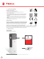
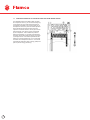
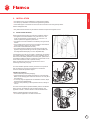
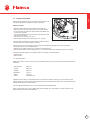
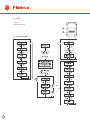
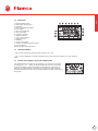
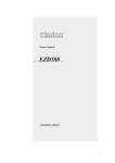
Flamco VHW 260
Sanitary heat pump
-10 °C to 35° C
Contents (adapt in own language)
ENG
Installation and user manual
3
2
BE
Flamco Belux
J. Van Elewijckstraat 59
B -1853 Grimbergen
+32 2 476 01 01
[email protected]
CH
Flamco AG
Fännring 1
6403 Küssnacht
+41 41 854 30 50
[email protected]
CZ
Flamco CZ
Evropská 423/178
160 00 Praha 6
+420 602 200 569
[email protected]
DE
Flamco GmbH
Steinbrink 3
42555 Velbert
+49 2052 887 04
[email protected]
DK
Flamco
Tonsbakken 16-18
DK-2740 Skovlunde
+45 44 94 02 07
[email protected]
EE
Flamco Baltic
Löötsa 6
114 15 Tallin
+ 372 56 88 38 38
[email protected]
FI
Flamco Finland
Ritakuja1
01740 Vantaa
+ 358 10 320 99 90
[email protected]
FR
Flamco s.a.r.l.
BP 77173
95056 CERGY-PONTOISE cedex
+33 1 34 21 91 91
[email protected]
HU
Flamco Kft.
(A Pest Megyei Bíróság mint Cégbíróság.
Cg.13-09-136479)
H-2330Dunaharaszti,
Jedlik Ányos út 25
+36 24 52 61 31
[email protected]
NL
Flamco B.V.
Postbus 502
3750 GM Bunschoten
+31 33 299 75 00
[email protected]
PL
FlamcoSp.zo.o.
ul. Akacjowa 4
62-002 Suchy Las
+48 616 5659 55
[email protected]
SE
Flamco Sverige
Kungsgatan 14
541 31 Skövde
+46 500 42 89 95
[email protected]
UAE
Flamco Middle East
P.O. Box 262636
JebelAli,Dubai
+971 4 881 95 40
[email protected]
UK
Flamco Limited
Washway Lane- St Helens
Merseyside WA10 6PB
+44 1744 74 47 44
[email protected]
ENG
Installation and user manual
Table of content
APPLICATION 1.1
1.2
1.3
1.4
1.5
1.6
1.7
GENERAL TECHNICAL SPECIFICATIONS APPLIANCE LAYOUT
WIRING DIAGRAM
STORAGE AND TRANSPORT
SCOPE OF SUPPLY OPERATING PRINCIPLE OF THE VENTILATION HEAT PUMP WATER HEATER 4
5
6
7
8
8
10
2.
SAFETY 11
2.1
2.1.1
2.1.2
2.1.3
SAFETY, CONTROL AND PROTECTION DEVICES HIGH PRESSURE SWITCH HIGH LIMIT SAFETY CUT-OUT TEMPERATURE SENSOR FOR AIR INLET 12
12
12
12
3.
INSTALLATION 13
3.1
3.2
3.3
3.4
3.4.1
INSTALLATION LOCATION CONNECTING THE CONDENSATE HOSE
CONNECTING THE DUCTS FILLING THE CYLINDER
WATER QUALITY 13
14
14
15
15
4.
USE 16
4.1
4.2
4.3
4.4
4.5
4.6
4.6.1
4.6.2
4.6.3
4.6.4
4.7
4.7.1
4.7.2
4.7.3
4.8
4.8.1
4.8.2
4.8.3
4.8.4
4.8.5
4.8.6
4.8.7
4.8.8
4.9
4.10
4.11
4.11.1
FLOWCHART MENU
OPERATION OPERATION MODES SETTING THE DOMESTIC HOT WATER TEMPERATURE MAIN MENU “PROG” SUBMENU - OPERATING MODES “MANUAL” OPERATING MODE “P1”, “P2” AND “P3” OPERATING MODES “FULL” OPERATING MODE “OFF” OPERATING MODE “MODE” SUBMENU - HEATING MODE ELECTRICAL HEATING MODE “HEAT PUMP” OPERATING MODE “COMBI” OPERATING MODE “SET” SUBMENU - SETTINGS DATE - SETTING THE TEMPERATURE UNIT, DATE, TIME AND DAY OF THE WEEK PROG - PROGRAMMING OF THE OPERATING TIMES “LEG” - AUTOMATIC THERMAL DISINFECTION « FAN » - FANSPEED « DUCT » - USE OF DUCTS “PURG” - DRAIN “FSET” - DEFAULT SETTINGS “INFO” SUBMENU – INFORMATION FAULT DIAGNOSIS DEFAULT SETTINGS FAULTS DISPLAY DISPLAY 16
17
17
17
18
18
18
19
19
19
19
20
20
20
20
21
21
23
24
24
24
24
25
25
25
26
26
5.
MAINTENANCE (YEARLY CHECK) 27
5.1
5.2
5.3
5.4
5.5
5.6
5.7
GENERAL INSPECTIONS CLEANING CONDENSATE PIPE REFRIGERANT CIRCUIT HIGH LIMIT SAFETY CUT-OUT DRAINING THE CYLINDER “SERVICE” MENU 27
27
27
27
28
28
28
6.
DISMANTLING, RECYCLING AND ENVIRONMENTAL PROTECTION 29
ENG
1.
4
3
ENG
Installation and user manual
Please read the installation instructions before installing the appliance!
Please read the operating instructions before commissioning the appliance!
Please observe the safety instructions in the operating instructions!
The installation location must meet the requirements for sufficient ventilation!
Installation must only be carried out by an authorized contractor!
1. APPLICATION
1.1 GENERAL
The appliance may only be used for DHW (Domestic Hot Water) heating. Using the boiler for any other purpose
will be considered incorrect use. Flamco accepts no liability for any damage resulting from such use.
The appliance is not suitable for commercial or industrial applications. It is approved for household use only.
De FLVHW 260 is a heat pump for DHW heating with the following specifications:
• (H) CFC-free polyurethane hard foam isolated (70 mm) vessel of stainless steel (1.4521);
• Indirect heating of DHW;
• Refrigerant R134a;
• Temperature DHW adjustable between 30° C to 70° C;
• Automatically switch-off heat pump at air temperature between -10°C to 35°C;
• Easy serviceable;
• No Fluor gases certification needed for changing the complete heat pump assembly
4
Heating output – in accordance with EN255-3, air temperature 20°C, heating water from 15°C to 45°C.
Unit
VHW 260
Output
kW
1,7*
Total heating output (including electric booster heater)
kW
3,7*
COP
-
4,3*
Standby energy consumption
kW/day
0,74*
Heating output – in accordance with 16147, XL cycle, air temperature
15°C, heating water from 10°C to 54°C.
ENG
1.2 TECHNICAL SPECIFICATIONS
VHW 260
COP
-
3,2*
Heating time (HP only)
-
8h48*
Standby energy consumption
kW/day
1,08*
Heating output – in accordance with 16147, XL cycle, air temperature
7°C, heating water from 10°C to 54°C.
VHW 260
COP
-
2,79*
Heating time (HP only)
-
10h38*
Standby energy consumption
kW/day
0,97*
General specifications
VHW 260
Description
-
Air/water heat
pump for DHW
use
Motor type Fan
-
DC
Adjustment range sp1/sp2 (without pipe work)
m3/h
380/490
Control ventilator
Adjustable by HMI
(2 speed)
IP-class
-
21
Refrigerant/mass
-/gram
R134a/400
Operating temperature
°C
-10 … +35
Maximum pressure compressor
bar
27
Reservoir capacity
liter
250
Maximum pressure vessel
bar
10
Sound level (distance 1 meter-380m3/h)
dB(A)
50 *
Power supply
V/Hz
230 /50
Max. power consumption
Watt
2600
Nominal current (HP-only/HP + immersion heater)
A
2,6/11,3
Start-up current
A
13,5 max.
Fuse rating
A
16
Electrical immersion heater
kW
2
Plug type
-
Type E
Labels and markings
-
CE/LCIE*/WEEE/
NF*/ RoHS/
REACH/ACS
*all these values can only be released or defined after the measurements done by LCIE.
5
ENG
Installation and user manual
1.3 APPLIANCE LAYOUT
15
6
7
8
9
16
2
5
4
13
10
17
2
11
1
3
[1] Water inlet – G3/4”
[2] Water outlet – G3/4”
[3] Thermal insulation
[4] Water inlet to condenser
[5] Water outlet from condenser
[6] Fan
[7] Evaporator
[8] Condenser (gas/water heat exchanger)
[9] Compressor
[10] Sensor pocket for DHW temperature sensor
[11] Electrical backup immersion heater
[12] Adjustable feet (3x)
[13] Air outlet aperture
[14] Air inlet aperture
[15] Condensate outlet
[16] Circulation pump
[17] Front protective covering
6
1
12
14
ENG
1.4 WIRING DIAGRAM
[1] NTC temperature sensor for air inlet
This ballon and component is added in this picture, not in EPS
[2] NTC temperature sensor
[3] NTC temperature sensor in water inlet
[4] Power cable
[5] High Pressure Switch
[6] Electrical capacitor for compressor
[7] Compressor
[8] High limit safety cut-out for compressor
[9] Circulation pump
[10] Fan
[11] Immersion heater
[12] High-limit safety cut-out for immersion heater
[13] Electronics box
[14] NTC temperature sensor (evaporator plates)
[15] Electrical capacitor for fan start
[16] Electrical capacitor for fan speed
[17] Defrost valve
7
ENG
Installation and user manual
1.5 STORAGE AND TRANSPORT
WARNING: Transport damage!
• Take care when handling the appliance.
• To avoid dropping and damaging the appliance, do not pivot it.
NOTICE: Transport damage!
• To avoid transport damage, do not remove the protective packaging. Wait
until the appliance is at the installation location to remove the protective
packaging.
• Transport and set down the appliance carefully. Jerky movements can
damage the components, the vessel and their connections or the external
casing.
• Use suitable means of transport to bring the appliance to theinstallation
location (special car, pallet truck, etc).
General information
The appliance is delivered on a single pallet and is protected against transport
damage by special packaging. The appliance must be stored and transported
vertically in its original packaging1 and the cylinder must be empty. Ambient
temperatures of -20 °C to +60 °C are permissible for storage and transport.
This device is not intended for use by persons (including children) with
physical, sensory or mental disability, of by persons with lack experience or knowledge, unless they have received
from a person in charge of their safety adequate supervision or preliminary instructions on how to use the device.
Dare must be taken at all times to keep children from playing with the device.
1.6 SCOPE OF SUPPLY
1-Flamco VHW 260
2-Set of documents
3-Condensate drain and hose pillar
1
2
Flamco VHW 260
Flamco VHW 260
Sanitary heat pump
-10 °C to 35° C
Contents (adapt in own language)
ENG
Installation and user manual
3
1 Horizontal transportation is permitted over short distances, provided that the conditions described above are fulfilled.
8
3
ENG
Data plate
The data plate is located on the rear side of the appliance.
1.6.1 ACCESSORIES
This table need to be determined.
Description
Article number
Safety valve
12450
….
….
….
….
….
….
Dimensions
9
ENG
Installation and user manual
1.7 OPERATING PRINCIPLE OF THE VENTILATION HEAT PUMP WATER HEATER
The Ventilation Heat Pump Water heater consists
of an expansion valve (1), an air heat exchanger (2),
a compressor (3) and a water heat exchanger (4).
A refrigerant circulates in the closed system (5). In
the expansion valve, the pressure and temperature
of the refrigerant are lowered, which becomes
vaporous. It extracts heat from the air (6) via the air
heat exchanger. The vapour is then compressed
by the compressor. This increases the pressure
and the temperature (7). The heat is transferred to
the water via the water heat exchanger (8). And the
cycle begins anew. It is therefore possible to heat
water with a low temperature of 10 ºC to domestic
hot water with a temperature of 60 ºC. This makes
it possible to create four parts of energy (heat) from
just one part of energy (electricity).
10
ENG
2. SAFETY
Installation
• The appliance may only be installed by an authorized contractor.
• Do not install the appliance in the following locations:
–– Outside
–– o in locations which promote corrosion
–– o in locations with a risk of frost
–– o in locations where there is a risk of explosion.
Check if a maximum temperature is specified by local, state or federal regulations is required. If so, a tempering
valve shall be installed at the DHW outlet!
Wait until the appliance is at the installation location to remove it from its packaging!
• All water connections must be checked for tightness before the appliance is connected to the power.
• Observe minimum clearances
• The electrical connection must comply with the local applicable regulations.
• Connect the appliance to an independent, earthed power source.
• Install a safety valve at the appliance’s cold water inlet.
• The drain line from the safety valve must be laid in a frost-free location. It must remain open to the atmosphere and
always be kept in a sloped position.
• Minimum and maximum water temperatures: 3 °C/80 °C
• Minimum/maximum water pressure: 0.2 bar/2 bar below the value of the installed safety valve
Risk of scalding at the hot water draw-off points
• When the appliance is in operation, temperatures in excess of 70 °C can occur. To limit the temperature at the tap,
install a thermal DHW tempering valve.
Service
• The end customer is responsible for safety and environmental compatibility during installation and service work.
• The appliance may only be serviced by an authorized contractor.
• Isolate the appliance from the power supply before performing any service work.
Service and maintenance
• Maintenance may only be carried out by an authorized contractor. Faulty maintenance may pose a danger to the
user and cause malfunctions in the appliance.
• Use only original spare parts.
• Have an authorized contractor perform an annual inspection and service the appliance as needed.
• Any work involving cooling gas may only be carried out by qualified contractors.
• Empty cylinders.
• We recommend that you arrange a maintenance and inspection contract with the manufacturer.
Room/inlet air
Keep the inlet air free of contaminants. It must not contain any of the following substances:
• corrosive substances (ammonia, sulphur, halogen products, chlorine, solvents)
• fatty or explosive substances
• aerosol concentrations
No other air inlet systems may be connected to the fan.
Refrigerant
• Please observe the applicable environmental regulations when using and reusing refrigerant. Do not release it into
the environment! Use the refrigerant R134a. It is nonflammable and does not damage the ozone layer.
• Before working on parts of the refrigerant circuit, remove the refrigerant for safety reasons.
Please note that HFC-134a and PAG-ÖL are used during service work. This is a chlorofluorocarbon and is rated with a
greenhouse potential of 1300 in the Kyoto Protocol.
Instructions to the customer
• Explain to the customer how the appliance works and how to operate it.
• Advise the customer that he/she must not make any modifications to the appliance or carry out any repairs on it.
11
ENG
Installation and user manual
Safety of electrical appliances for domestic use and similar purposes
The following requirements apply in accordance with EN 60335-1 in order to prevent hazards from occurring
when using electrical appliances: “This appliance may be operated by children aged 8 or over and by people with
full physical, sensory and mental capabilities who have the necessary training and experience to use this type of
appliance. They must be supervised or instructed on how to use the appliance safely and on the associated risks.
Children must not play with the appliance. Children must not clean or service the appliance without supervision.”
“Damaged power cables must be replaced by the manufacturer, the service department or a qualified contractor in
order to prevent hazards.”
2.1 SAFETY, CONTROL AND PROTECTION DEVICES
2.1.1 HIGH PRESSURE SWITCH
If the operating pressure is outside of the recommended range, the pressure switch switches off the appliance and
displays a fault.
2.1.2 HIGH LIMIT SAFETY CUT-OUT
The high limit safety cut-out ensures that the water temperature in the cylinder does not exceed the prescribed limit.
If the temperature limit is exceeded, the DHW heating shuts down. The reset is performed manually by a certified
contractor.
2.1.3 TEMPERATURE SENSOR FOR AIR INLET
The temperature sensor measures the temperature of the inlet air in the evaporator. If the measured value is outside
the operating temperature range, DHW heating automatically switches from the “Combi” operating mode to “Electric
booster heater”. If the appliance is in the “Heat pump” operating mode, DHW heating is interrupted until the
temperature returns to within the permissible range.
12
ENG
3. INSTALLATION
• The appliance may only be installed by an authorized contractor.
• The heat pump installation must follow the applicable regulations.
• Check that all pipe connections are intact and have not shaken loose during transportation.
NOTICE: Refrigerant leak!
• Only authorized contractors are permitted to maintain and repair the refrigerant circuit.
3.1 INSTALLATION LOCATION
Please note the following when choosing the installation location:
• The appliance must be installed in a dry, frost-free room. The
supply air temperature must be between -10 °C and 35 °C in
order to optimize the appliance performance.
• The appliance must be installed on a sufficiently strong and level
surface.
• The air outlet and air inlet must not be in locations where there is
a risk of explosion cause by gas, steam or dust.
• Ensure that condensate drains correctly.
• The surface below the appliance must be strong enough (the
appliance weighs about 400 kg when the cylinder is filled, with
the weight distributed equally over its 3 adjustable feet).
If the appliance only has one duct (inlet or outlet duct), its operation
may create negative or positive pressure in the installation room. If
other burners are already installed in the same place, please bear in
mind that the appliance requires a clearance of at least 220 cm2 for
the air inlet and outlet in order to operate correctly.
Note: The clearance of 220 cm2 is required for the correct
functioning of the heat pump only.
Fig. 1
To ensure faultless operation and easy access to all components
and connections for service and maintenance, maintain the
minimum clearances specified in figure 1.
Installing the appliance
• Remove external protective packaging.
• Lift the appliance from its pallet and position it on its final plinth.
Watch out for damaging the metal hood of the HP-unit. Only lift at
the vessel part!
• To correctly align the appliance at the installation location, adjust
the height of the adjustable feet.
• Assure correct positioning of all temperature sensors, see figure
2 and 3.
Fig. 2
To ensure that the system operates faultlessly and the condensate
drains correctly, the appliance must be aligned vertically. The
appliance must tilt 1°, into the direction of the condensate drain.
NOTICE: Possible damage to external casing!
• Do not tilt the appliance on his feet more than 20°.
Fig. 3
13
ENG
Installation and user manual
3.2 CONNECTING THE CONDENSATE HOSE
Damage to the appliance! Connect the condensate hose to the
condensate drain before installing the part.
• Do not bend the condensate hose!
The condensate is drained on the rear side of the appliance,
see figure 4.
• Connect the condensate hose to the condensate drain (1)
• Connect the condensate hose to the collection area.
• Drain off condensate via a siphon drain (2)
Don’t disconnect the condensate hose from the condensate drain,
this will damage the connection in the foam!
Fig. 4
3.3 CONNECTING THE DUCTS
The air inlet can be located in the installation room, in a different room or outside. In the latter two cases, air inlet
ducts must be installed. If ducts are used select “ducts on”. (see 4.8.5)
To ensure maximum appliance performance and to prevent condensation forming on the external duct walls, use
thermally and acoustically insulated ducts.
When choosing a room for the air inlet, observe the average air temperature and required air flow rate. In order to
minimize air resistance, lay the air inlet and outlet ducts (Ø 160 mm) as straight as possible.
The length (Leq) of the air inlet and outlet ducts must not exceed the following values:
• 30m at fan speed 1 (SP1)
• 30m – 60m at fan speed 2 (SP2)
Air inlet
Air outlet
0,5 m duct
0,5 m
1 m duct
1,0 m
2m duct
2,0 m
10 m hose
19,0 m
45° elbow
0,9 m
90° elbow
2,0 m
90° flexible curve
2,3 m
Weather grille
8m
4m
Roof output
7m
4m
To ensure that condensate forming in the air inlet and air outlet
ducts drains from the appliance:
• Install air ducts at a slight angle to the air inlet and air outlet
apertures on the top side of the appliance.
Always use insulated pipes to prevent condensate at the air inlet
and the air outlet. By the use of outside air condensate can occur.
It’s recommended to use SP2 if ducts are used with a high
resistance. (To select SP2 see 4.8.4)
Please note that a high ventilator volume results in a higher sound
level.
14
ENG
3.4 FILLING THE CYLINDER
Damage to the appliance! Prior to commissioning the appliance, fill
the cylinder with water and bleed the system if necessary.
Filling the cylinder
• Open the water outlet valve and at least one hot water tap.
• Open the water inlet valve on the cylinder. The cylinder is filled.
• Do not close the hot water taps until the water flows steadily and
is free from air bubbles.
• Connect the appliance to the power supply via a separate socket
with an earth connection.
• Call up the “Purg” function. (see 4.8.6)
• Set the selector switch on the DHW pump to “III”. (Fig.5(1))
CAUTION: Risk of scalding! Ensure that draining water from the air
vent screw presents no risk to people or property.
Fig. 5
Open the drain screw on the heating pump (Fig.5(2)) until the water flows steadily and without air bubbles.
• Close the drain screw on the heating pump.
• Wait around 5 minutes until the “Purg” operating mode has finished.
• Set the selector switch on the heating pump to “I”. The process of draining and filling the cylinder is complete.
If the fault code “E09” appears on the display after a few minutes, proceed as follows:
• Clear the fault
• Refill manually.
3.4.1 WATER QUALITY
Water quality varies, in order to ensure a long and trouble free life the heat pump the following values should not be
exceeded.
Total hardness
200 p.p.m.
Chloride
250 p.p.m.
Sulphate
250 p.p.m.
Magnesium
10 p.p.m.
Sodium
150 p.p.m.
pH Min
6.5 and Max 8.5
Inadequate water quality or contaminated water can damage the appliance. Scaling is more important at higher
water temperature. In case of water hardness above 600 mg/l, the Langelier saturation index must be determined to
evaluate the necessity for water treatment.
Check the guideline 98/83/EG for the minimal requirements about potable water.
Note: In regions with more corrosive water, safety measures (filter, etc.) must be taken. The first inspection must
always take place 6 months after installation.
15
ENG
Installation and user manual
4. USE
1. Display
2. Mode Selector keys
4.1 FLOWCHART MENU
16
ENG
4.2 OPERATION
1. Electrical heating mode
2. DHW heating by heat pump
4. Information
5. Input of adjustable parameters
6. Error display
7. Service menu selection
8. days of the week
9. “Auto/Man” operation
10. ON/OFF indicator
11. “Prog” menu selection
12. Setting the hour
13. Runtime
14. Power consumption
15. Code for cylinder temperature sensors
16. Frost protection
Refresh numbers, table and picture.
4.3 OPERATION MODES
“ auto” symbol is displayed • operating times as set (P1, P2 or P3).
“ man “ symbol is displayed • Continuous operation (24 h/7 days) without time setting or in “Full” operating
mode.
4.4 SETTING THE DOMESTIC HOT WATER TEMPERATURE
The water temperature is set to 50 °C at the factory. This value can be changed
by pressing the “+” or “-“ button to set the desired value. Pres the “ OK” button
to confirm the setting. The set value flashes unit the setting is confirmed. If the
setting is not confirmed within 10 seconds, the previously set value is retained.
Once the temperature has been set, the display indicates the water temperature in
the cylinder.
17
ENG
Installation and user manual
4.5 MAIN MENU
Calling up the main menu:
Press and hold the “Menu button for max. 3 seconds. Once you have called
up the main menu, you can select the following menus/submenus:
• Prog - Operating modes
–– Manual
–– P1
–– P2
–– P3
–– Full
–– Off
• Mode - Heat types
–– “Electrical” operating mode
–– “Heat pump” mode
–– “Combi” operating
• Set settings
–– Date
–– Prog- Programming of the operating times
–– Leg – Legionella program
–– Fan - Fan speed
–– Duct – use of ducts
–– Purg – Drain
–– Fset – Default setting
• Info
Use the “+”or “- “button to select the required menu. Confirm by pressing “ok”. To switch to the previous menu press
the “Menu” button or do not press any button for 15 seconds.
4.6 “PROG” SUBMENU - OPERATING MODES
You can set 7 different operating times in the “Prog” submenu.
• Manual
• P1
• P2
• P3
• Full
• Off
4.6.1 “MANUAL” OPERATING MODE
Selecting this operating mode puts the appliance into continuous operation in
order to keep the temperature at the set value for a longer period of time. The
heat appliance can be set in the main menu using the “Mode” function.
18
ENG
4.6.2 “P1”, “P2” AND “P3” OPERATING MODES
“P1” operating mode selecting this menu causes the appliance to run according to the factory-set operating times.
“P2” and “P3” operating modes Selecting this menu causes the appliance to run according to the user-set operating
times.
4.6.3 “FULL” OPERATING MODE
In this operating mode, two heat appliances are used at the same time: the
heat pump and the electric booster heater.
The appliance performance decreases in “Full” operating mode. For this
reason, it must only be used when the water temperature needs to be
increased rapidly.
The water temperature can be set to between 30 °C and 70 °C.
Both heat appliances are used at the same time until the desired temperature
is reached. Only the electric booster heater is used at temperatures above 60
°C. The display shows “Full” until the desired temperature is reached.
As soon as the set DHW temperature is reached, the appliance switches from
the “Full” operating mode back to the previously set operating mode. “Quick”
activation of the “Full” operating mode • Press and hold the “+” and “-”
buttons for more than 3 seconds.
4.6.4 “OFF” OPERATING MODE
In this operating mode, the appliance is switched off. If necessary, the electric
booster heater is switched on by itself for the frost protection function.
Frost protection
The electric booster heater starts up when the water temperature in the
cylinder falls to 5 °C and switches off again when the temperature reaches
8 °C.
4.7 “MODE” SUBMENU - HEATING MODE
3 different types of heating mode can be selected in the “Mode” submenu.
• Electrical heating mode
• “Heat pump” operating mode
• “Combi” operating mode
19
ENG
Installation and user manual
4.7.1 ELECTRICAL HEATING MODE
In this operating mode, the electric booster heater is the only heat appliance
used. The water temperature can be set to between 30 °C and 70 °C.
4.7.2 “HEAT PUMP” OPERATING MODE
Water heating is only guaranteed when the inlet air temperature is between
-10 °C and 35 °C. Selecting this operating mode means that the heat pump is
the only heat appliance used. The water temperature can be set to between
30 °C and 60 °C. At very low temperatures, the frost protection function is
activated.
4.7.3 “COMBI” OPERATING MODE
In this operating mode, two heat appliances are used depending on the
situation: the heat pump or the electric booster heater. The water temperature
can be set to between 30 °C and 70 °C. If the water temperature in the
cylinder below 60 °C and the inlet air temperature is between -10 °C and 35
°C, the heat pump is the only heat appliance used. Otherwise, the electric
booster heater is switched on.
4.8 “SET” SUBMENU - SETTINGS
You can set various parameters in the “Set” submenu:
• Date
• Prog - Operating times
• Leg - Legionella
• Duct - use of ducts
• Purg - Drain
• Fset - Default settings
20
ENG
4.8.1 DATE - SETTING THE TEMPERATURE UNIT, DATE, TIME AND DAY OF THE WEEK
1. Select the temperature unit using the “+” or “-” button.
2. Confirm by pressing “OK”. The year flashes on the display.
3. Set the year using the “+” or “-” button.
4. Confirm by pressing “OK”. The month flashes on the display.
5. Set the month using the “+” or “-” button.
6. Confirm by pressing “OK”. The day flashes on the display.
7. Set the day using the “+” or “-” button.
8. Confirm by pressing “OK”. The day flashes on the display.
9. Set the day of the week using the “+” or “-” button.
10. Confirm by pressing “OK”. The hour flashes on the display.
11. Set the hour using the “+” or “-” button.
12. Confirm by pressing “OK”. The minutes flash on the display.
13. Set the minutes using the “+” or “-” button.
14. Confirm by pressing “OK”.
15. The process of setting the clock is complete.
Monday is set as the first day of the week by default. Depending on individual
requirements, the user can choose to set a different day as the first day of the
week.
4.8.2 PROG - PROGRAMMING OF THE OPERATING TIMES
In the “Prog” submenu, you can set the operation period for the heat pump.
The following menus can be called up in the “Prog” submenu:
• “P1” operating time (days 1 to 5)
• “P1” operating time (days 6 and 7)
• “P2” operating time (days 1 to 5)
• “P2” operating time (days 6 and 7)
• “P3” operating time (days 1 to 5)
• “P3” operating time (days 6 and 7)
“P1” operating time
The heat pump only goes into operation during the operating times
set at the factory. These cannot be changed: Days 1 - 5: [00:00 •
06:00] and [16:00 • 19:00] Days 6 - 7: [02:00 • 08:00]
21
ENG
Installation and user manual
“P2” and “P3” operating times
The heat pump runs according to the operating times set by the user.
Setting the operating times for “P2” and “P3”
4 operating times are set for each function:
• 2 operating times for days 1 to 5
• 2 operating times for days 6 and 7
Setting the operating times
• Call up function “P2” or “P3”.
• Press “OK”. The start of the first operating time flashes.
• Set the start of the operating time using the “+” and “-” buttons.
• Press “OK”. The end of the first operating time flashes.
• Set the run time using the “+” and “-” buttons.
• Press “OK”. The start of the second operating time flashes.
If the start of the second operating time is set so that it is within the first
operating time, the first operating time ends automatically when the second
operating time starts.
• Set the start of the second operating time using the “+” and “-” buttons.
• Press “OK”. The end of the second operating time flashes.
• Set the run time using the “+” and “-” buttons.
• Press “OK”. The operating time for days 1 to 5 is saved.
• Repeat the steps above for the operating times for days 6 and 7.
Once you have set the second operating time for days 6 and 7, the process of
setting the operating times is complete.
1. Start of the first operating time
2. End of the first operating time
3. Start of the second operating time
4. End of the second operating time
Deleting the operating time
• Set the start and end of the operating time to the same time. The operating
time is deleted.
If you do not wish to set a second operating time:
• Set the start and end of the second operating time to the same time.
The display will show “--:--”.
22
“
“ symbol is displayed During appliance operating time.
“
“ symbol is displayed Outside of appliance operating time.
ENG
4.8.3 “LEG” - AUTOMATIC THERMAL DISINFECTION
The “Leg” function allows you to activate/deactivate thermal disinfection.
This process is used to kill bacteria and must be performed by the user at
least once a week.
This function is deactivated on the appliance at the factory. When the
disinfection is activated, all other settings are temporarily suspended.
WARNING: Risk of scalding!
Hot water can lead to severe scalding. Only schedule thermal disinfection for periods outside normal usage times.
Inform occupants of the building of the danger of scalding and always monitor the thermal disinfection process. Install
a thermostatic DHW mixer.
The disinfection takes max. 48 h. During the first 24 hours, the appliance is in the “Combi” operating mode. If it does
not reach 70 °C, the appliance switches to the “Full” operating mode for the next 24 hours.
Activating the automatic “Leg” function
• Call up the “Leg” function and press “OK”. “man “ flashes on the display.
• Press “+”. “auto” flashes on the display.
• Press “OK”. The “Leg” function is activated and the first day of the week flashes.
• Set the day of the week for disinfection. Select the day using the “+” and “-” buttons.
• Press “OK”.
• Set the time for disinfection.
• Select the time using the “+” and “-” buttons.
• Press “OK”.
As soon as the temperature reaches 70 °C, the appliance switches back to the previously set operating mode.
Activating the manual “Leg” function
• Call up the “Leg” function and press “OK”.
• “man” flashes on the display.
• Press “OK”. The “Leg” function is active.
As soon as the temperature reaches 70 °C, the appliance switches back to the previously set operating mode.
Cancelling the “Leg” function.
• Call up the “Leg” function and press “OK”. “man” flashes on the display.
• Press “+” until the display shows “LstP”.
• Press “OK”. The current Legionella program is cancelled.
This only ends the current program; the weekly repetition is still active.
23
ENG
Installation and user manual
4.8.4 « FAN » - FANSPEED
The fan can be used at two speeds
Switching on the « FAN » function
• Select « FAN» function and press « OK ». The display shows
“SP1”.
• Press « + » or « - » to define the fan speed:
–– « SP1 » : fan speed 1 (low air volume)
–– « SP2 » : fan speed 2 (high air volume)
• Press «OK».
4.8.5 « DUCT » - USE OF DUCTS
Switching on the « Duct » function
• Select « Duct » function and press « OK ». The display shows “dOFF”.
• Press « + » or « - » to define the use of ducts:
–– « dOFF » : installation without ducts
–– « dON » : installation with ducts
• Press «OK».
4.8.6 “PURG” - DRAIN
The “Purg” function can be used to drain air from the system.
Switching on the “Purg” function.
• Call up the “Purg” function and press “OK”. The pump is switched on.
The display indicates the time remaining until the draining procedure is
complete (in minutes). After 5 minutes, the appliance reverts to the previously
selected operating mode.
4.8.7 “FSET” - DEFAULT SETTINGS
The “Fset” function can be used to restore the default settings.
Switching on the “Fset” function
• Call up the “Fset” function and press “OK”. The display shows “Fset”.
• Press “OK”. After 10 seconds, the default settings are restored
24
ENG
4.8.8 “INFO” SUBMENU – INFORMATION
With the “Info” function, it is possible to display the total consumption for
the last 30 days.
Displaying the consumption
• Call up the “Info” function and press “OK”. The display shows the total
consumption (in kWh).
Resetting the consumption
The display shows the total consumption.
• Press “-”. “Del” flashes on the display.
• Press “OK”. The counter is reset.
4.9 FAULT DIAGNOSIS
The appliance is equipped with a system for fault diagnosis. Malfunctions are
displayed on the digital display by means of a fault code and a fault symbol.
The fault must be eliminated and the appliance recommissioned before it is
ready for use again.
Resetting the fault display
• Press and hold the “OK” button for at least 3 seconds.
4.10 DEFAULT SETTINGS
After setting the temperature units and the time, the appliance adopts the
default settings.
• Heating mode: “Combi”
• Operating mode: “Manual”
• Selected temperature: 50 °C
25
ENG
Installation and user manual
4.11 FAULTS DISPLAY
Installation, service and maintenance may only be carried out by a certified contractor. The following table lists the
fault codes and their remedies.
Display
Description
Remedy
E01
Fault in the temperature sensor at
the top of the cylinder
Notify certified contractor
E02
Notify certified contractor
E03
Temperature sensor for air inlet not
working
Notify certified contractor
E04
Temperature in cylinder > 80 °C
If the problem persists after pressing
“OK”, notify a certified contractor.
E05
NTC temperature sensor (evaporator
plates) not working
Notify certified contractor
E06
Setting buttons hold down for longer
than 30 seconds.
Release buttons
E07
Notify certified contractor
E08
System emptied incorrectly Water
shortage (> 12h) Fault in the pump
Clear the fault Notify certified
contractor
E10
Resistor not working
High limit safety cut-out not working
Temperature of high limit safety
cut-out set to a lower value than
the appliance
Notify certified contractor
E11
Fault in the fan
Pressure loss in the pipes
Leaks in refrigerant circuit
Fault in the compressor
Expansion valve not working
Drying filter not working
Notify certified contractor
Display
Description
Remedy
HOT
Supply air temperature > 35 °C
COLD
Fault in the temperature sensor
System stops automatically in the
“Heat pump” operating mode if the
air inlet temperature is below -10 °C
or above 35 °C. General operating
conditions are checked on an hourly
basis.
4.11.1
26
Notify certified contractor
E09
DISPLAY
ENG
5. MAINTENANCE (YEARLY CHECK)
DANGER: Risk of electric shock!
• Isolate the appliance from the power supply using the fuse or another protection device before carrying out any
work on electrical parts.
NOTICE: Damage to the appliance!
• Do not shut off the water supply while the appliance is in operation.
5.1 GENERAL INSPECTIONS
Check the appliance regularly for faults.
• Keep the appliance and the installation location clean.
• Dust the system regularly using a damp cloth. In this way, leaks can be identified and repaired at an early stage.
• Check all connections regularly for tightness.
5.2 CLEANING
• Check and clean the evaporator regularly.
• The air inlet and air outlet apertures must be unobstructed and accessible.
• Check the air grille, air filter and air ducts regularly and clean them if necessary.
5.3 CONDENSATE PIPE
• Check the drain and/or hose for contamination and clean if necessary. Don’t disconnect the condensate hose form
the condensate drain, this will damage the foam.
5.4 REFRIGERANT CIRCUIT
NOTICE: Refrigerant leak!
Maintenance work may only be carried out on the refrigerant circuit (e.g. on the compressor, condenser, evaporator,
expansion vessel, etc.) by a certified contractor.
C:\Users\kochjy\Desktop\cotherm.JPG
27
ENG
Installation and user manual
5.5 HIGH LIMIT SAFETY CUT-OUT
The appliance is equipped with an automatic safety facility. This
safety facility switches off the DHW cylinder in order to prevent the
risk of injury if the DHW cylinder water temperature rises above a
certain limit.
NOTICE: The high limit safety cut-out may only be reset by a
qualified contractor! The high limit safety cut-out must be reset
manually, but only once the cause of the fault has been eliminated.
Resetting the high limit safety cut-out
• Remove the front protective covering.
• Remove the protective cap from the heating element.
Temperature control unit
1. Reset button
2. Temperature setting of the high limit safety cut-off
After resetting, ensure that the temperature controller is in the position shown in figure.
5.6 DRAINING THE CYLINDER
CAUTION: Risk of scalding! Check the appliance’s DHW temperature before opening the safety valve. Wait until the
water temperature has dropped enough to prevent scalding and other damage!
• Isolate the appliance from the power supply.
• Close the water shut-off valve at the cold water inlet and open one DHW tap.
• Open the drain tap.
-or• Open safety valve.
• Wait until the water stops flowing out of the safety valve drain tap and the appliance has been completely drained.
5.7 “SERVICE” MENU
This menu is meant to assist the contractor and may be used by the contractor only.
28
ENG
6. DISMANTLING, RECYCLING AND ENVIRONMENTAL PROTECTION
Environmental protection is one of the fundamental company policies of the Flamco Group. Product quality, efficiency
and environmental protection are equally important objectives for us. We comply with all environmental protection
laws and regulations. In order to protect the environment, we use the latest technologies and the best materials whilst
bearing in mind the economic implications.
Packaging
Where packaging is concerned, we participate in the relevant local recycling systems in order to ensure optimum
recycling. All of our packaging materials are environmentally friendly and can be reused.
Identifying plastics
Used appliances contain materials that can be reused. The assemblies
are easy to separate and the types of plastic are identified. In this
manner the individual components are easily sorted and added into
the recycling and disposal systems.
Obsolete equipment
Used appliances contain materials that can be reused. The assemblies
are easy to separate and the types of plastic are identified. In this
manner the individual components are easily sorted and added into
the recycling and disposal systems.
29
Copyright Flamco B.V., Bunschoten, the Netherlands.
Nichts aus dieser Ausgabe darf ohne ausdrückliche Freigabe und mit
Angabe der Quelle vervielfältigt oder auf irgendeine andere Weise
veröffentlicht werden. Die erwähnten Angaben gelten nur für die
Anwendung von Flamco Produkten. Für eine unsachgemäße Nutzung,
Anwendung oder Interpretation der technischen Daten übernimmt
Flamco B.V. keine Haftung. Technische Änderungen vorbehalten.
No part of this publication may be reproduced or published in any way
without explicit permission and mention of the source.
The data listed are solely applicable to Flamco products.
Flamco B.V. shall accept no liability whatsoever for incorrect use,
application or interpretation of the technical information.
Flamco B.V. reserves the right to make technical alterations.
MC00701/12November20131:29PM
Copyright Flamco B.V., Bunschoten, die Niederlande.