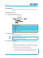
1
because it works Operation manual FOUR VALVE PUMP Version: ❍ NDP 865.22 RS ❍ NDP 1140.17 RS ❍ NDP 1820.2 RS ❍ NDP 1820.4 RS Factory No.: …………………… Translation of the original operation manual •Vierventilpumpe_1203_en•ski Declaration of Installation Declaration of Installation according to Appendix ll, No. 1 B of the Machinery Directive 2006 / 42 / EC including last changed by 2009 / 127 / EC The company WIWA Wilhelm Wagner GmbH & Co. KG Gewerbestr. 1-3 35633 Lahnau Germany herewith declares that the equipment types Four valve pump: NDP 865.22; NDP 1140.17; NDP 1820.2; NDP 1820.4 Factory-No.: are incomplete machines according to Article 2 g and designed exclusively for installation or assembly with another machine or item of equipment. These devices meet the following underlying safety and health and safety requirements from the above guideline: Appendix I Articles: 1.1.2, 1.1.3, 1.1.5, 1.1.6, 1.3.1, 1.3.2, 1.3.4, 1.3.7, 1.4.1, 1.5.2, 1.5.3, 1.5.4, 1.5.6, 1.5.7, 1.5.8, 1.6.1, 1.6.2, 1.6.4, 1.7.1, 1.7.3, 1.7.4.1, 1.7.4.2 Commissioning of the incomplete machine is prohibited until it has been established that the end product into which this machine is to be installed corresponds to the conditions of the EC Machinery Directive (2006/42//EC). Teh special technical documents are prepared in accordance with Appendix VII Part B of this guideline. Documentary authority: WIWA GmbH / Tel. +49 6441 609 0 The manufacturer undertakes to send by electronic means the special documents for the incomplete machine to single-nation bodies upon request. . Lahnau, 26.03.2012 Place, Date Heidrun Wagner-Turczak Managing Director Copyright ownership for this user manual remains with WIWA Wilhelm Wagner GmbH & Co. KG Gewerbestr. 1-3 • 35633 Lahnau • Germany Phone: +49 6441 609-0 • Fax: +49 6441 609-50 E-Mail: [email protected] • Homepage: www.wiwa.de This operating manual is solely intended for personnel involved in preparation, operation and servicing. It is prohibited to pass on this operating manual for reproduction, utilisation or communication of its contents, unless this has been explicitly permitted. Infringements incur an obligation to pay damage compensation. All rights reserved in the event of registration of the patented design, industrial design or registered design. This operating manual only applies in conjunction with the machine card that was given to you with the user manual for your equipment. Please check that the type plate data is identical with the information on the machine card. Please notify us immediately if there are discrepancies, if the user manual has been incorrectly compiled or if the type plate is missing. 2 Translation of the original operating manual •Vierventilpumpe_1203_en•ski * = optionally available Copyright © 2011 WIWA Contents Contents Declaration of Installation................................................................................. 2 1 Foreword......................................................................................................... 5 1.1 Important for your safety 1.2 Machine card 1.3 Pictogrammes 1.4 Notices on the machine 5 5 6 7 2 Safety Information......................................................................................... 8 2.1 Danger sources 2.1.1 Dangers caused by the spray jet 2.1.2 Danger to health 2.1.3 Notices on the permissible operating pressure 2.1.4 Gefahr durch Explosion 2.1.5 Danger caused by disregarding the explosion protection 2.2 Operating personnel 2.3 Protective equipment 2.4 Safety features 2.5 Handling the system and auxiliary materials 2.6 Emergency procedures 2.6.1 Leakages 2.6.2 Injuries 2.6.3 Fires 8 8 9 9 10 10 11 11 12 13 13 13 13 13 3 Machine Description.................................................................................... 14 3.1 Intended use of the machine 3.2 Note on warranty 3.3 Machine surroundings 3.3.1 Emissions 3.3.2 Sound pressure level 3.4 Transporting the machine and additional equipment 3.5 Place of installation of the machine 3.6 Storing the machine and additional equipment 3.7 Disposal of the machine and additional equipment 3.8 Unit variants 14 14 15 15 15 15 16 16 16 17 * = optionally available 4 Installation and Assembly........................................................................... 18 4.1 Assembly options 4.1.1 Assembly on drum 4.1.2 Assembly in system 4.2 Setting up the unit 4.3 Ground the system 4.4 Check the condition of the release agent 4.5 Compressed air connection 5 Commissioning............................................................................................ 22 Translation of the original operating manual •Vierventilpumpe_1203_en•ski 18 18 19 20 21 21 21 3 Contents 6 Operation...................................................................................................... 24 7 Decommissioning........................................................................................ 26 8 Pressure relief.............................................................................................. 27 9 Accessories*................................................................................................. 28 9.1 Maintenance unit* 9.1.1 Components of maintenance unit 9.1.2 Check lubricant 9.1.3 Adjusting the fog oiler 9.1.4 Draining the condensation water 9.1.5 Notes on oil reservoir and water separator 9.2 Material filter* 9.2.1 Changing and cleaning the filter element or the O-ring 28 28 28 28 29 29 30 30 10 Maintenance............................................................................................... 31 10.1 Check cycles 10.2 Important notes 10.3 Release agents 10.3.1 Fill release agent 10.3.2 Replace release agent 10.4 Readjust packing 31 31 31 32 32 32 11 Malfunctions and Troubleshooting.......................................................... 34 12 Appendix..................................................................................................... 36 36 36 37 * = optionally available 12.1 Technical data 12.2 Operating materials 12.3 Instruction Certificate 4 Translation of the original operating manual •Vierventilpumpe_1203_en•ski Foreword 1 Foreword 1.1 Important for your safety Operating personnel should always have access to this user manual! The owner of the unit must ensure that the operator of the unit always has an operating manual at his/her disposal in a language he/she understands! All persons involved in the set-up, commissioning, operation, maintenance, repair and servicing of the machine must have read and understood the user manual beforehand, and the chapter on Safety in particular. We recommend to the owner of this unit to have this confirmed in writing In principle you should refrain from any work method that would affect the safety of products and the operating personnel. Please read and comply with: ➤➤ the applicable guidelines for your country. In Germany, these are the “Richtlinien für Flüssigkeitsstrahler” (Guidelines for Liquid Jets), issued by: the Hauptverband der Gewerblichen Berufsgenossenschaften. ➤➤ The manufacturer's instructions and processing guidelines for coating or transfer materials are to be respected at all times. This machine has been designed and manufactured under due consideration of all safety-related aspects. It corresponds to the current standard of technology and to applicable accident prevention regulations. The machine left the factory in perfect condition and guarantees a high level of technical reliability and safety. Nevertheless, there are certain risks that can arise from incorrect operation or misuse: ➤➤ to life and limb of the operator or third party, ➤➤ to the machine and other material assets of the owner, ➤➤ to efficient work with the machine. 1.2 Machine card This user manual is only valid in combination with the following machine card. * = optionally available The machine card contains all important and safety relevant data and information about the machine. ➤➤ exact designation and manufacturer data ➤➤ technical data and limiting values ➤➤ equipment and test certificate ➤➤ data of purchasing ➤➤ Machine identification (machine components and accessories with article and spare parts numbers) Notice The data on the machine card must match the data on the type plate. In case of discrepancies or if the type plate is missing please notify us immediately. Translation of the original operating manual •Vierventilpumpe_1203_en•ski 5 Foreword 1.3 Pictogrammes The notices and symbols used in this manual have the following meanings: Attention! marks a potentially dangerous situation. Disregarding this information can result in severe injuries! Risk of explosion! Highlights a situation with potential danger of explosion. Disregarding this information can result in severe or even fatal injuries! Notice! Indicates an informative text passage. You should pay particular attention when reading it. The following symbols indicate that protective equipment should be worn. With your health in mind you should always comply with the recommendations of the material manufacturer. Wear protective clothing Highlights the order to wear the prescribed protective clothing to protect against skin injuries caused by spraying material or gases. Wear ear defenders Highlights the order to use ear defenders in order to prevent your sense of hearing from being damaged by noise. Use eye protection Highlights the order to use eye protection in order to prevent your eyesight from being damaged by material splatter. Use a respiratory protection mask Highlights the order to use a respiratory protection mask in order to prevent your respiratory tract from being damaged by gases, fumes or dusts. Wear protective gloves Highlights the order to use protective gloves in order to prevent the skin from being damaged by burning. Drum “material to be processed” + “cleaning agent” Drum “empty” Identifies an empty collecting vessel to be used by the user to collect contaminated spraying material. 6 Translation of the original operating manual •Vierventilpumpe_1203_en•ski * = optionally available Identifies a drum containing the material to be applied, which the user requires at the corresponding location in the manual. Foreword 1.4 Notices on the machine Appropriate information signs and symbols on the machine refer to possible danger areas and must be respected at all costs. Information signs and symbols must not be removed from the machine. Damaged and illegible information signs and symbols must be replaced immediately. The following signs can be found on the machine: ➤➤ Type plate Please check that the type plate data are identical with those on the machine card. In case of discrepancies or if the type plate is missing please notify us immediately. ➤➤ Warning sign on grounding the machine, (Fig. 1.1) For version with material filter only* * = optionally available According to the accident prevention instructions BGR 500, Chapt. 2.29 the owner is obliged to ground this piece of equipment. Please follow our operating instructions! Translation of the original operating manual •Vierventilpumpe_1203_en•ski 7 Safety Information 2 Safety Information 2.1 Danger sources Four-valve pumps can cause life-threatening injuries if used improperly! All persons involved in setting up, commissioning, operation, maintenance, repair and servicing of the machine must have read and understood the user manual beforehand, and the chapter Safety Note in particular. In principle you should refrain from any work method that would affect the safety of products and the operating personnel. 2.1.1 Dangers caused by the spray jet Attention! The material leaves the spray gun under high pressure. Due to its cutting effect the spray jet can cause severe injuries by penetrating the skin or entering into the eyes. ➤➤ Never point the spray gun at yourself, other persons or other living beings. ➤➤ Do not hold your fingers or hands into the spray jet. ➤➤ Do not reach with your hands into the spray jet. Attention! From leakage points material can escape under very high pressure and cause serious bodily injuries and material damage. Never try to seal leakages on connections and high pressure hoses by hand or by wrapping fabric around them. ➤➤ Depressurize the the complete system. ➤➤ Replace defective components. ➤➤ Never repair material hoses. * = optionally available Attention! Components which do not comply with the maximum permissible working pressure may quickly burst and cause severe injuries. Please check: ➤➤ Material hoses and hose assemblies must comply with the maximum working pressure and the required safety factor. ➤➤ Material hoses must be leak tight and free of kinks, signs of abrasion or bulges. ➤➤ Hose connections must be tight. 8 Translation of the original operating manual •Vierventilpumpe_1203_en•ski Safety Information Attention! In case of material congestion or agglomeration of material in the spraying system, residual pressures can still be present despite pressure discharge. In case of necessary repair work on the plant escaping residual pressures may cause accidents. Please bear in mind: ➤➤ Repair work must only be performed by trained personnel. ➤➤ Be extremely careful when disassembling material hoses and spray gun. ➤➤ When disconnecting material hoses you should cover the screw fitting with a cloth to catch any escaping material sprays. ➤➤ Switch off the machine before starting maintenance and cleaning work on the unit and the spraying accessories. ➤➤ Relieve the pressure in the entire system before starting maintenance and cleaning work on unit and accessories. 2.1.2 Danger to health In closed or pressurized systems, in which aluminium components or galvanized parts have contact with the cleaning agent, hazardous chemical reactions may occur when using 1.1.1-trichloroethane (TCE), methylene chloride or other solvents containing chlorinated hydrocarbons (CFCs). If you wish to use the aforementioned solvents or varnishes and paints containing such solvents, we advise you to consult the - customer service or directly. We would like to point out that we have a series of dual component systems in rust and acid proof design available for such materials. 2.1.3 Notices on the permissible operating pressure The maximum operating pressure specified by us must generally be adhered to for all parts (e.g. four valve pump, safety valve, etc.). At varying operating pressures the lowest value is always valid as the maximum admissible operating pressure for the entire system. General example: Pump up to Material hose up to 200 bar 600 bar * = optionally available The maximum permissible operating pressure for the entire system in this example is 200 bar. The existing air inlet pressure on the four valve pump must be easy to read using a pressure gauge. Devices which have a maintenance unit* or a compressed air regulator* must be fitted with a pressure gauge. Translation of the original operating manual •Vierventilpumpe_1203_en•ski 9 Safety Information Danger! Any sudden overpressure in the system can lead to the bursting of components. This may result in damage to persons and property. ➤➤ Never allow the system to run without safety valves. If the safety valve needs to be replaced, you can find the corresponding order number on the machine card. ➤➤ When using new safety valves make sure that the valves have been set to the max. permissible air inlet pressure of the four valve pump (see type plate) and lead sealed. 2.1.4 Gefahr durch Explosion CAUTION! The high flow velocities associated with the Airless spraying method may cause static charging. Static discharges can cause fire and explosion. ➤➤ Always use open containers! ➤➤ Never spray solvents or solvent containing materials into cone-top cans or drums with bunghole! ➤➤ Stand the containers on a grounded surface. ➤➤ When using metal containers watch out for contact between spray gun and container wall. ➤➤ Only use conductive material hoses. All original material hoses are conductive and perfectly adapted to our equipment. Risk of explosion! Heating up cleaning agents can cause an explosion. This can cause severe injuries to body and eyes. ➤➤ Pay attention to the flashpoint and the ignition temperature of the cleaningagent! ➤➤ Switch off the material flow heater if you need to perform the following work on the system: –– Cleaning –– Pressure tests –– Preparation work –– Decommissioning –– Maintenance and repair 2.1.5 Danger caused by disregarding the explosion protection The system must NOT be operated in explosion protection zones! Note! Smoking, naked flames and/or any potential sources of ignition are not permitted anywhere in the working area. 10 Translation of the original operating manual •Vierventilpumpe_1203_en•ski * = optionally available Spraying equipment designed without explosion protection must not be used in workshops that come under the explosion protection ordinance. Safety Information 2.2 Operating personnel Juveniles under the age of 16 have no permission to operate this equipment. The owner of the machine must ensure that the user manual is made available to the user and make sure that the user has read and understood its contents. Setup, cleaning, maintenance and repair work: Before starting work you must interrupt the compressed air supply to the machine. Make sure that the machine is free of residual pressure, in both the air and the material side. After the completion of work you must in any case check the function of all protective devices and the correct function of the machine. Activity Qualification of personnel Service work instructed user Setup work Cleaning work Maintenance work Repair work instructed user instructed user personnel trained by personnel trained by - Customer service - Customer service 2.3 Protective equipment We would like to point out that the valid guidelines and stipulations depending on the work environment (mining, closed rooms, etc) must be respected in any case. Always wear the protective clothes specified by the material manufacturer to avoid injuries. The sound pressure level of this unit is less than 85 db(A). However, operating personnel should still be provided with suitable noise protection equipment. It is recommended that the operator should always wear a respiratory protection mask, even though the paint mist has been minimized in Airless spray painting applications with correct pressure setting and working mode. Wear protective goggles to protect against eye injuries caused by mechanical or chemical influences. * = optionally available Wear protective gloves with lower arm protection to avoid burn injuries. Translation of the original operating manual •Vierventilpumpe_1203_en•ski 11 Safety Information 2.4 Safety features All safety features must be checked: ➤➤ before each start-up of the equipment! ➤➤ before starting work on or with the equipment! ➤➤ after completion of setup work! ➤➤ after cleaning and servicing work! ➤➤ after maintenance and repair work! Check list to check the safety features on the depressurized unit Please check: ❏❏ the lead seal on the safety valve for damage. ❏❏ the safety valve for external damage. ❏❏ grounding cable* for damage. ❏❏ grounding cable* connections on unit and conductor. ❏❏ the correct function of the compressed air shut-off valve*. Attention! Not fully functional safety features or other deficiencies on the machine can lead to malfunctions. This may cause serious injuries to persons and damage to property. ➤➤ Stop operation of the system immediately! ➤➤ Operation of the system must only be resumed after the correct functional state has been re-established. All units are delivered with the following safety features: Safety valve, (Fig. 2.1) The safety valve makes sure that the max. permissible air inlet pressure at the air motor is not exceeded. The safety valve will open and vent off air when the air inlet pressure exceeds the set limiting value. Grounding cable*, (Fig. 2.2) Grounding cable The system must be connected to an electrically conductive object with a a grounding cable, to prevent electrostatic charging. A connection for the grounding cable is located at the exhaust manifold of the material pump, (). A grounding cable is already fitted in the version with material filter*. Fig. 2.2 12 Translation of the original operating manual •Vierventilpumpe_1203_en•ski * = optionally available Fig. 2.1 Safety Information Air shut-off* For conventional sprays, always install a compressed air shut-off valve* (if not installed already) at the air inlet of the four valve pump. This enables immediate shutting down of the unit. Before working in the unit, you must first relieve the pressure in the pump to allow the residual pressure in the unit/system to dissipate 2.5 Handling the system and auxiliary materials ➤➤ Follow the safety notes and dosing information of the manufacturers and the generally applicable regulations when handling spraying materials, cleaning agents, oils, greases and other chemical substances. 2.6 Emergency procedures 2.6.1 Leakages 2.6.2 Injuries ➤➤ Immediately consult a physician if injured when handling fluid jets (because of their cutting effect)! ➤➤ Read and comply with the instructions for fire alarm and escape routes, which are displayed in your factory or at any work place. ➤➤ Only use the extinguishing substances stipulated by the material manufacturer. * = optionally available 2.6.3 Fires ➤➤ In case of leakages the system must be shut down immediately and the complete system must be depressurized: ❏❏ Disconnect the compressed air supply: ❏❏ Depressurize the the complete system. ❏❏ Faulty parts must be replaced immediately. Translation of the original operating manual •Vierventilpumpe_1203_en•ski 13 Machine Description 3 Machine Description 3.1 Intended use of the machine Four valve pumps are used for material feeding in paint circulator systems and dispensing stations in trade and industry. Depending on the version in use, four valve pumps can be used for processing low viscosity drum materials (varnishes, paints, water-based coatings, solvents, oils and finishes, etc.). ➤➤ These pumps are fitted with appropriate packages depending on the processing material and are available in rust- and acid-resistant versions. ➤➤ When using circulation systems (continuous fed), a stroke frequency of 20 dual strokes per minute should not be exceeded. Each unit has been especially adapted to the processing material and is to be used for this purpose only. Any other use is deemed to not be in accordance with regulations. The manufacturer's approval must be obtained before units are used for any other purpose or with other materials, i.e. not in accordance with the intended use, otherwise the warranty will become null and void. Intended use also includes compliance with the technical documentation and adherence to the prescribed operating, servicing and maintenance guidelines. 3.2 Note on warranty Unauthorized conversions or alterations should not be undertaken on safety grounds. Protective equipment should not be dismantled, converted or bypassed. Use of components which have not been manufactured or delivered by renders any warranty null and void. The unit should only be operated within the prescriptive limit values and machine parameters. * = optionally available Notice: Dangers caused by accessories and spare parts: If you use original accessories and spare parts, their suitability for use with our equipment is guaranteed. It is, however, mandatory to respect the safety regulations of the accessories and spare parts. These safety regulations are found in the corresponding user manuals for the accessories. If foreign accessories or spare parts are used, the company cannot guarantee the safety of the entire system. Similarly liability is null and void for damages or injuries incurred through use of those accessories and spare parts. 14 Translation of the original operating manual •Vierventilpumpe_1203_en•ski Machine Description 3.3 Machine surroundings 3.3.1 Emissions Depending on which materials are processed, hazardous fumes may be generated. For this purpose, always ensure for sufficient aeration and ventilation at the workplace for avoiding damage to your health and property. You should always follow the processing information issued by the material manufacturers. 3.3.2 Sound pressure level The sound pressure level of this unit is less than 85 db(A). However, operating personnel should still be provided with suitable noise protection equipment. The operator is responsible for adhering to noise and vibration protection regulations. For this purpose, pay special attention to the conditions of the setting up location, e.g. will the noise exposure increase if the system is set up in or on hollow bodies. 3.4 Transporting the machine and additional equipment Notice: The systems leave the factory in flawless condition and are appropriately packed for transport. Upon arrival you should check the system for any apparent transport damage. * = optionally available ➤➤ Disconnect the entire power supply for the machine, even for short transport distances. ➤➤ Empty the machine before transport. ➤➤ Remove all loose components (e.g. tools) from the unit. ➤➤ Caution when loading with hoisting gear! ❏❏ When using hoisting gear ensure sufficient load bearing capacity. ❏❏ Never stand under suspended loads or inside the loading area. This poses a danger to life! ❏❏ Use only appropriate transport vehicles with sufficient load bearing capacity. You will find the dimensions and weights of the equipment in chap. „12.1 Technical data“, on page 36. ➤➤ Secure the load on the transport vehicle against slipping and falling off. ➤➤ Parts or equipment that have been removed for transport purposes must be attached professionally and in accordance with the intended use before commissioning. Translation of the original operating manual •Vierventilpumpe_1203_en•ski 15 Machine Description 3.5 Place of installation of the machine ➤➤ When installing the four valve pump in a system (e.g. in a paint circulation system) pay attention to the information in the operating manual for the entire system. ➤➤ Do not block access to safety devices. ➤➤ Always keep the working area, especially all walkways and standing areas, clean and tidy. Clean up spilled materials or cleaning agents immediately. ➤➤ Always ensure adequate ventilation ate the work place to avoid damage to health and objects. Always observe the processing instructions issued by the material manufacturers. ➤➤ The owner must protect the entire system by undertaking appropriate lightning protection measures. ➤➤ Strictly comply with the valid accident prevention instructions. Attention! If the unit is used outdoors, a lightning can cause a dangerous situation for the operator. ➤➤ Never operate the unit outdoors when there is a thunderstorm! 3.6 Storing the machine and additional equipment ➤➤ Store the machine in a frost-free, vibration free, dry and possibly dust free environment. ➤➤ The machine and its implements must under no circumstances be stored outside closed rooms. 3.7 Disposal of the machine and additional equipment * = optionally available ➤➤ Clean the unit thoroughly of all material residues. ➤➤ Disassemble the entire unit and separate the materials. ❏❏ Take metal parts to scrap metal services. ❏❏ Plastic parts can be disposed of through the household waste. ➤➤ Rests of spraying material, cleaning agent, oils, greases and other chemical substances must be collected in accordance with statutory provisions concerning recycling and waste disposal. The official local waste water laws are valid. 16 Translation of the original operating manual •Vierventilpumpe_1203_en•ski Machine Description 3.8 Unit variants Unit type NDP 865.22 RS A = Air inlet / B = Material inlet / C = Material outlet A C Fig. 3.1 NDP 1140.17 NDP 1820.2 R B without illustration A C B Fig. 3.2 NDP 1820.4 RS A * = optionally available C Translation of the original operating manual •Vierventilpumpe_1203_en•ski B Fig. 3.3 17 Installation and Assembly 4 Installation and Assembly 4.1 Assembly options The valve pumps can be mounted directly onto a drum, into a circulation- of feeder system, or into a frame. The illustrations shown are only examples. The type of unit you have chosen and the accessories used are crucial for ensuring optimum results and must be adapted to the intended use as appropriate. Notice: The four valve pump comprises rust and acid-free material. To ensure total resistance to corrosion, use stainless steel pipes.. 4.1.1 Assembly on drum Assembly plate (optional) ø hole circle for fixing bolts 4x ø12 mm 266 mm ø Drum opening at least. 247.5 mm * = optionally available Fig. 4.1 18 Translation of the original operating manual •Vierventilpumpe_1203_en•ski Installation and Assembly 4.1.2 Assembly in system C D P A D B A B Fig. 4.2 Pos. Description Compressed air connection* with compressed air shut-off valve* maintenance unit* with compressed air regulator* Material drum* A+B Material shut-off valve* A+B on material drum Material inlet Material discharge Pressure relief valve* P+D Material shut-off C+D valve* on pressure compensation drum* * = optionally available Pressure compensation drum* Material shut-off valve* after pressure compensation drum* Task Shut-off compressed air supply when performing servicing, cleaning and maintenance work The compressed air is mixed with oil to prevent corrosion to the air motor. The compressed air regulator regulates the speed of the air motor. Shut-off material supply when performing servicing, cleaning and maintenance work. Release the material pressure in the material pump before performing servicing, cleaning and maintenance work Ward against serious bodily injury caused by the escape of pressurised materials. Shut-off material supply when performing servicing, cleaning and maintenance work. Prevents material from flowing back into the pump and compensates for any fluctuations in material output. Shut-off material supply when performing servicing, cleaning and maintenance work Translation of the original operating manual •Vierventilpumpe_1203_en•ski 19 Installation and Assembly 4.2 Setting up the unit Prerequisites All materials to be processed must be supplied from the manufacturer with data concerning viscosity, application temperatures, mixing ratios, etc. If this is not the case, consult the corresponding manufacturer and ask for these data. ➤➤ The spray material must be mixed slowly but surely before beginning work. For optimal preparation of the materials offers a wide range of accessories, like e.g.: –– agitators in various sizes –– material preheating containers in different sizes –– Material Flow Heater ➤➤ Make sure all system parts are leak-free at all times! ➤➤ Do not use cone-top cans! Always wear the specified protective clothes. Procedure 1. Check the permissible highest pressure for all accessories: It must be higher than or equal the maximum operating pressure of the four valve pump as specified on the type plate. 2. Compare the maximum operating pressure of the safety valve with the specifications on the type plate. These data must match. 3. Consider the required floor space - see chap. „12.1 Technical data“, on page 36. ❏❏ All operating elements must be easily accessible. ❏❏ The access to the safety features must be kept clear. 4. Connect the parts/accessories (e.g. maintenance unit*, compressed air regulator*, material hose*) removed for transport to the unit . 5. Screw the unit securely onto a drum, frame or into a system. Attention! Material emerging from the connections can cause severe physical injuries and damage to property. Check all rotatable parts, nuts, screws and hose connections and tighten these properly. * = optionally available Note! To prevent the ingress of dirt and oversized material particles, we recommend you also mount a suction filter* on the material inlet. This will minimise the wear on the pump. 20 Translation of the original operating manual •Vierventilpumpe_1203_en•ski Installation and Assembly 4.3 Ground the system The high flow velocities associated with the spraying method may cause static charging. Static charges can cause fire and explosion. ➤➤ Ground the complete system. System component Four valve pump Material hoses* System components Material drum (external) Object to be sprayed Cleaning agent container Description of grounding by means of a grounding cable*: Fixing bolt on exhaust manifold of material pump, (Figure 4.3) conductive material hoses, e.g. original material hoses Grounding is accomplished in connection with the - material hoses. Grounding acc. to local regulations. 4.4 Check the condition of the release agent ➤➤ Fill the unit with release agents, see chap. „10.3 Release agents“, on page 31. ➤➤ Does not apply for assembly on drums! ➤➤ Check the release agent level - see also chap. „10.3 Release agents“, on page 31. 4.5 Compressed air connection Connect the unit to the local compressed air supply. ❏❏ The diameters of the air supply hoses must match the connections on the equipment. ❏❏ Version with maintenance unit*: Carry out the settings shown in chap. „9.1 Maintenance unit*“, on page 28. Attention! Unexpected activation of the four valve pump can cause serious injury or damage to the unit. * = optionally available For this reason, install a compressed air regulator* and a compressed air shut-off valve* in the vicinity of the four valve pump to allow the compressed air to be regulated and shut off. Translation of the original operating manual •Vierventilpumpe_1203_en•ski 21 Commissioning 5 Commissioning After assembly in the factory the correct functioning of this machine was checked with a testing medium. The entire system must initially be flushed with the cleaning agent recommended by the material manufacturer and belonging to the material, before it is filled with the material to be applied, to make sure that the material to be processed is not contaminated by the testing medium. Prerequisites The unit has been set up and connected as specified in chap. „4 Installation and Assembly“, on page 18. The following is required 1x 1x 2x Always wear the specified protective clothes. Procedure 1. Begin with the supply of compressed air and cleaning agent Risk of explosion! Cleaning agents are highly flammable and can cause explosions when heated. This may result in damage to persons and property. Remember the flash point of the cleaning agent! Do not switch on any heater when using cleaning agents! Open the material valves* Begin feeding compressed air Attention! Ensure slow running of the pump! * = optionally available 22 Translation of the original operating manual •Vierventilpumpe_1203_en•ski Commissioning 2. Rinse unit/system Duration: until clean, bubble-free material starts to run out Note! If several spray guns are connected, open them in sequence. Check drum contact! 3. End supply of compressed air and cleaning agent * = optionally available Shut off the compressed air supply Close the material valves* Translation of the original operating manual •Vierventilpumpe_1203_en•ski 23 Operation 6 Operation Always wear the specified protective clothes. 1. Prepare the material Open the material valves* Begin feeding compressed air Attention! Ensure slow running of the pump! Note! During operation keep checking the material feed to the unit, to prevent the development of friction heat caused by dry running of the material pumps. Please note: ❏❏ no empty material drums while the material pumps are running. ❏❏ Suction systems must not be clogged, kinked or defective. ❏❏ The unit must immediately switch off if no material is delivered. 2. Pump out the remaining cleaning agent and fill pump with material Risk of explosion! Cleaning agents are highly flammable and can cause explosions when heated. This may result in damage to persons and property. Remember the flash point of the cleaning agent! Do not switch on any heater when using cleaning agents! Requirement:- after initial commissioning - after all service work Duration: until clean, bubble-free material starts to run out Note! If several spray guns are connected, open them in sequence. 24 * = optionally available Check drum contact! Translation of the original operating manual •Vierventilpumpe_1203_en•ski Operation 3. Pressure tests Check the entire system for leakages. In case of leakages stop operation immediately and have the malfunction corrected by expert personnel. 4. Open deicing (units with air motor LM 333 only) Open the deicing regulator at the air motor Fig. 6.1 Note! The deicing may stay open over the entire life cycle of the equipment. 5. Configure the maintenance unit* Read chap. „9.1 Maintenance unit*“, on page 28. 6. Replace the filter element in the material filter* Read chap. „9.2 Material filter*“, on page 30. 7. Check condition of release agent Read chap. „10.3 Release agents“, on page 31. 8. Set the operating pressure * = optionally available Material pressure = air inlet pressure x pressure ratio Translation of the original operating manual •Vierventilpumpe_1203_en•ski 25 Decommissioning 7 Decommissioning Always wear the specified protective clothes. 1. End supply of compressed air and material Shut off the compressed air supply Close the material valves* * = optionally available 2. Relieve pressure in unit according to chap. „8 Pressure relief“, on page 27 26 Translation of the original operating manual •Vierventilpumpe_1203_en•ski Pressure relief 8 Pressure relief Always wear the specified protective clothes. 1. Shut off the compressed air supply 2. Close the material valves* 3. Relieve spray gun* Note! If several spray guns are connected, open them in sequence. Check drum contact! * = optionally available 4. Open pressure relief valves* Translation of the original operating manual •Vierventilpumpe_1203_en•ski 27 Accessories* 9 Accessories* The accessories are optionally available and are not included in the unit's scope of supply. 9.1 Maintenance unit* 9.1.1 Components of maintenance unit Compressed air connection at air motor Fig. 9.1 Pos. 1 2 3 4 5 6 Designation Setscrew for fog oiler Filler plug Slide Oil tank Water release agent Drain valve 9.1.2 Check lubricant Check the lubricant for the air motor in the container of the maintenance unit and top up slightly, if required. Note! High humidity can cause icing of the motor. In case of icing use pure anti-freeze agent. 9.1.3 Adjusting the fog oiler 1. Allow the air motor to run slowly with an air inlet pressure of approx. 4 bar. 2. Check: 1 drop of lubricant after approx. every 10 - 15 double strokes of the air motor If necessary adjust the regulating screw on the lubricator with a screw driver. –– The maintenance unit must never be operated without oil. –– The max. oil level is indicated by a circumferential groove in the bowl. –– To fill the oil bowl loosen the filling screw and fill the reservoir directly. 28 Translation of the original operating manual •Vierventilpumpe_1203_en•ski * = optionally available 3. Check the amount of oil in the oil container every day. Accessories* Note! Only use the lubricants and anti-freeze agents mentioned in chap. „12.2 Operating materials“, on page 36. Fig. 9.2 9.1.4 Draining the condensation water 1. The accumulated condensate is automatically drained off through the drain valve. For this purpose hold the hose into an empty collecting vessel. 2. Check the bowl regularly for dirt residues and clean it as required. Fig. 9.3 9.1.5 Notes on oil reservoir and water separator ➤➤ Disassembly: –– Press the slide down. –– Turn the bowl anti-clockwise. * = optionally available ➤➤ Assembly: –– Make sure the O-ring is correctly fitted. Translation of the original operating manual •Vierventilpumpe_1203_en•ski 29 Accessories* 9.2 Material filter* Attention! Before you begin servicing the material filter*, always disconnect the entire power supply and carry out a pressure relief according to ´chap. „8 Pressure relief“, on page 27. ➤➤ Clean the filter element in the material filter* each time the material is replaced or daily. ➤➤ The filter element* must be suited to the spray material and spray gun*! ➤➤ The mesh size must always be slightly finer than the bore of the nozzle used. ➤➤ Do not use a filter element when applying coarse pigmented or fibre filled materials. Filter element Nozzle size overto M 200 (white) M 150 (red) - 0,23 mm / 009“ 0,33 mm /.013“ 0,38 mm / 015“ 0,23 mm /.009“ M 100 (black) M 70 (yellow) 0,33 mm / 013“ 0,38 mm /.015“ M 50 (orange) 0,66 mm / 026“ 0,66 mm /.026“ - 9.2.1 Changing and cleaning the filter element or the O-ring 1. Unscrew the cap with the pin spanner 2. Loosen the nut with an open end spanner and remove the filter element. 3. Clean the filter element. For this purpose use only the cleaning agent matching the Material. Replace the filter element, if it shows any signs of damage. 4. Replace the O-ring if it is leaking. 0 Ig Pressure relief valve Filter element Nut Fig. 9.4 O-ring cap Note! Material filters* in R- and RS version It is mandatory to slightly grease the threads for easier assembly/disassembly. 30 Translation of the original operating manual •Vierventilpumpe_1203_en•ski * = optionally available Maintenance 10 Maintenance 10.1 Check cycles According to the accident prevention instructions for “Work with fluid spraying equipment” BGR 500, chapter 2.36, the unit needs to be inspected and serviced regularly by an expert ( Customer Service). The unit needs to be inspected: ➤➤ before initial commissioning, ➤➤ after the modification or repair of parts of the system, which could affect safety, ➤➤ after work breaks longer than 6 months, ➤➤ but at least every 12 months. For decommissioned units the inspection can be postponed until the next commissioning. The inspection results must be recorded in writing and kept until the next inspection. The inspection report or a copy thereof must be available at the place of use of the equipment. 10.2 Important notes Attention! Disassembling the pressurized spraying unit can cause severe injuries to body and eyes. ➤➤ Always switch off the unit before starting maintenance and repair work. ➤➤ Depressurize the the complete system. ➤➤ Be extremely careful when disassembling material hoses*and spray gun*. ➤➤ Before disassembly cover the screw connections on the material hoses with a cloth to catch possible material spatter. ➤➤ During assembly apply a thin coat of thread paste on all threads. This prevents damage to the thread during assembly and makes disassembly easier. 10.3 Release agents Note! Not applicable to drum version! * = optionally available Filling release agents into the release agent cup prevents the formation and hardening of material deposits on the piston. Check the release agent at regular intervals. Replace the packing in good time to prevent early appearance of wear on the piston. Colour changes in the release agent indicate faulty packages which reduces the performance of the system. Translation of the original operating manual •Vierventilpumpe_1203_en•ski 31 Maintenance 10.3.1 Fill release agent Before each time you commission, check the condition of the release agent and replenish as required. 1. Bring the piston rod of the material pump into the lower position. 2. Fill the release agent until just over the edge of the bores in the packing nut. Fig. 10.1 3. In the event of a discoloration, replace the packing as shown in chap. „10.4 Readjust packing“, on page 32. Every 50 operating hours check the release agent for discolouration caused by spraying materia 10.3.2 Replace release agent In case of slight discolouration 1. Empty the release agent cup. 2. After examination top up with a clean amount of release agent. In case of excessive discolouration and high spraying material content 1. Clean the release agent cup. 2. Replace the upper pump packing (see Spare parts list for the material pump) and top up with new release agent. 10.4 Readjust packing Note! Not applicable to drum version! 1. Stop the pump during its downwards movement. 2. Before each readjustment of the packing, perform a pressure relief of the * = optionally available unit according to chap. „8 Pressure relief“, on page 27. 3. Readjust the new packing while the pump is stationary. 32 Translation of the original operating manual •Vierventilpumpe_1203_en•ski Maintenance Tighten packing nut as required! Fig. 10.2 4. Fill new release agent into the release agent cup according to chap. „10.3.1 Fill release agent“, on page 32. 5. If the release agent continues to be contaminated by material discharge, this * = optionally available means the packages are worn and will have to be replaced. Translation of the original operating manual •Vierventilpumpe_1203_en•ski 33 Malfunctions and Troubleshooting 11 Malfunctions and Troubleshooting Fault Pump not running.. Possible cause Remedy ➤➤ Compressed air supply disconnected. ➤➤ Check compressed air supply. ➤➤ Ball valves blocked. ➤➤ Dismantle and clean pump. ➤➤ Material blocked. ➤➤ Clean or replace material line carefully. ➤➤ Material filter* blocked. ➤➤ Clean or replace material filter*. ➤➤ Air motor faulty/ control unit blocked. ➤➤ Contact Customer Service.. The pump runs evenly but ➤➤ The ball is stuck at the inlet valve ➤➤ Lift the ball in the inlet valve to does not draw in any mate(dried-on material). release it. rial. ➤➤ The suction pipe is leaky in the screw fitting. ➤➤ The suction filter* is contaminated. Pump is operating irregularly, reduced pump performance. ➤➤ Tighten suction pipe and reseal the screw fittings where necessary. ➤➤ Clean suction filter*. ➤➤ The viscosity of the conveying material is too high. ➤➤ Dilute conveyor agent or use a more powerful pump. ➤➤ Valves are contaminated. ➤➤ Clean system and where necessary leave to stand in dilution. ➤➤ The valves, packings or piston rod are worn. ➤➤ Replace the worn parts. ➤➤ Pump pressure too low. ➤➤ Increase the air inlet pressure. ➤➤ The viscosity of the conveying material is too high. ➤➤ Dilute conveyor agent or use a more powerful pump. ➤➤ The suction filter* and/or material ➤➤ Clean the filters*. filter* is/are blocked. ➤➤ The air motor control is defective ➤➤ Contact Customer Service. ➤➤ Use a more powerful pump. . ➤➤ Wear on packing, valves or piston rod. ➤➤ Replace worn parts. ➤➤ Overpressure valve in lower section faulty ➤➤ Replace overpressure valve. * = optionally available Pump continues to operate even when discharge points are closed. ➤➤ The unit is being overstretched. 34 Translation of the original operating manual •Vierventilpumpe_1203_en•ski Malfunctions and Troubleshooting Fault The air motor freezes Possible cause Remedy ➤➤ The number of strokes is too high. ➤➤ Reduce the air inlet pressure. You may need to use a more powerful pump. ➤➤ Inlet air contains too much condensate. ➤➤ Install maintenance unit* if not already installed. Empty water separator more often. ➤➤ Fill oiler on maintenance unit* with anti-freeze and adjust so that a drop are released every 5 to 10 double strokes. * = optionally available ➤➤ Very unfavourable operating conditions (high air humidity or temperatures around freezing point). Translation of the original operating manual •Vierventilpumpe_1203_en•ski 35 Appendix 12 Appendix 17:1 1140 8 136 G 1" 1820.2 R/K 2:1 1820 8 16 1820.4 RS/K 4:1 1820 8 32 G /2" 1 G 1" G 1 /2" G 11/2" 1 G 1 /2" 1 Dimensions approx. (mm) 1140.17R G 11/2" Weight approx. (kg) 176 G 1" Material outlet max. operating pressure (bar) 8 Material inlet Pump capacity per double stroke (cm³) 22:1 865 Air inlet Pressure ratio 865.22 RS Pump capacity per double stroke (cm³)m3) Model 12.1 Technical data G 1" 98 478 x l* G 1" 55 ø 292 x l* G 1" 65 ø 292 x l* G 1" *l => customer-specific length can be found in the original drawing Model Air motor Material pump 865.22 RS 333 / 120 865 - 120R 1140.17 RS 333 / 120 1140 - 120R 1820.2 RS 140 / 120 1820 - 120R 1820.4 RS 200 / 120 1820 - 120R Emitted sound pressure level at the work place in idle (LpAd ) (dB) at 8 bar air inlet pressure loaded (LpAd ) (dB) at 8 bar air inlet pressure 84 80 12.2 Operating materials Designation Order no. 0163333 Pneumatic oil (0.5 litres) Anti-freeze agent 2 2 Retention agent (50 ml)3 Thread paste (450 g)3 Lubricant (acid-free grease)3 36 Order no. 0632579 Order no. 0631387 Order no. 0000233 Order no. 000015 Order no. 000025 Translation of the original operating manual •Vierventilpumpe_1203_en•ski * = optionally available Release agent Order number 1 Appendix )1 Plasticizer to fill into the release agent cup of the material pump )2 for maintenance unit )3 Materials required for cleaning and repair work (see information in spare parts lists) 12.3 Instruction Certificate This certificate follows the EC-Directive for working utensils 85/655/EEC, section II article 7. The owner of the device specified below has instructed the operating personnel. Manufacture Type designation Year of construction Serial-number The instruction was conducted by the representative of the owner: Foreman or responsible superior, name, department The instructed person has read and understood the user manual for the equipment listed above, especially the chapter about safety, and declares that he is able to operate the unit in a safe way. Personnel for: Operation Date, name Repair and maintenance * = optionally available Electrics / electronics Translation of the original operating manual •Vierventilpumpe_1203_en•ski 37 Headquarter and production WIWA Wilhelm Wagner GmbH & Co. KG Gewerbestr. 1 – 3 • 35633 Lahnau • Germany Tel +49 6441 609-0 • Fax +49 6441 609-50 E-Mail: [email protected] • Homepage: www.wiwa.de WIWA partnership in USA WIWA LP 107 N. Main St. P.O. Box 398, Alger, OH 45812 Tel.: +1 (419) 757-0141 Fax: +1 (419) 549-5173 Toll Free: +1(855) 757-0141 E-Mail: [email protected] Homepage: www.wiwa.com WIWA subsidiary in China WIWA Taicang Co., Ltd. Add: No.87 East Suzhou Rd., Taicang city, Jiangsu province 215400, P.R.China Tel: +86 512-5354 8858 Fax: +86 512-5354 8859 E-Mail: [email protected] Homepage: www.wiwa-china.com Your contacts throughout the world Michel Laksander Sales Representative France Mobil: +33 6 37 01 92 97 Tel.: +33 3 23 62 11 20 E-Mail: [email protected] 2 Bis rue de léglise, F-02240 Brissy Hamegicourt, France Wolfgang Pucken Director International Sales North of Germany, Israel, Hungary, Romania, Turkey, Poland, Malta, India, Pakistan, Africa, Morocco Mobil: +49 173 5432559 Tel.: +49 2226 12708 Fax: +49 2226 13973 Frankenstraße 37, 53359 Rheinbach-Oberdrees Germany Robert Jansen Director International Sales Finland, Sweden, Norway, Denmark, Scotland, England, Holland, Belgium, France, Spain/Portugal, Italy, Croatia, Greece, Czech Republic, Slovakia, Slovenia, Luxembourg, Bulgaria, Egypt, Libya, Dubai, Abu Dhabi, Catar, Bahrain, Kuwait, Saudi Arabia, Iran, Oman Otto Dietrich Director International Sales Russland, Ukraine, Weisrussland (Belarus), Moldawien, Baltische Staaten (Litauen, Lettland, Estland) Kaukasische Staaten (Armenien, Azerbeidzhan, Georgien), Asiatische Staaten (Kasachstan, Uzbekistan, Turkmenistan, Kirgizistan, Tadzhikistan) Mobil: +31 6 18 88 40 97 Tel.: +31 33 494 69 81 Fax: +31 33 494 75 83 E-Mail: [email protected] Rietgans 38, 3752 KH Bunschoten The Netherlands Mobil: +49 160 1574385 Tel.: +49 6742 899336 Fax: +49 6742 899337 E-Mail: [email protected] Binger Gasse 34, 56154 Boppard Germany