1
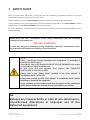
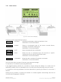
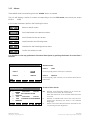
GE Digital Energy User Manual Uninterruptible Power supply IEMi Intelligent Energy Management integrated GE Consumer & Industrial SA General Electric Company CH – 6595 Riazzino (Locarno) Switzerland T +41 (0)91 / 850 51 51 F +41 (0)91 / 850 52 52 www.gepowerquality.com imagination at work Model: IEMi - Intelligent Energy Management integrated for SG Series CE version and SG Series UL version Issued by Product Document Department – Riazzino - CH Date of issue: 20.08.2010 File name: OPM_OPT_IEM_XXX_XXX_XGB_V010 Revision: 1.0 Identification No. 25202 - IEMi factory license <160kVA 25203 - IEMi factory license 160kVA+ 25204 - IEMi field upgrade kit <160kVA 25205 - IEMi field upgrade kit 160kVA+ Up-dating Revision Concern Date COPYRIGHT © 2010 by GE Consumer & Industrial SA All rights reserved. The information contained in this publication is intended solely for the purposes indicated. The present publication and any other documentation supplied with the UPS system is not to be reproduced, either in part or in its entirety, without the prior written consent of GE. The illustrations and plans describing the equipment are intended as general reference only and are not necessarily complete in every detail. The content of this publication may be subject to modification without prior notice. Modifications reserved OPM_OPT_IEM_iXX_XXX_XGB_V010.doc Page 2/24 User Manual IEMi - Intelligent Energy Management integrated Dear Customer, We thank you for selecting our products and are pleased to count you amongst our very valued customers at GE. Please read carefully the User Manual, which contains all the necessary information and describes all you need to to know about the use of IEMi - Intelligent Energy Management integrated. Thank you for choosing GE ! Table of contents 1 2 3 Page SAFETY RULES................................................................................................................................... 4 DESCRIPTION .................................................................................................................................... 5 SETUP ................................................................................................................................................. 6 3.1 CONTROL PANEL – GRAPHIC DISPLAY ............................................................................................................................................6 3.1.1 3.1.2 3.1.3 3.1.4 3.1.5 Home screen..................................................................................................................................................................................................... 7 Metering.............................................................................................................................................................................................................. 8 Alarms............................................................................................................................................................................................................... 10 Setup.................................................................................................................................................................................................................. 12 Commands ..................................................................................................................................................................................................... 16 3.2 CONTROL PANEL – LCD DISPLAY.................................................................................................................................................... 17 3.2.1 3.2.2 3.2.3 4 5 6 Metering mode.............................................................................................................................................................................................. 18 Alarms............................................................................................................................................................................................................... 19 User parameters .......................................................................................................................................................................................... 20 OPERATION ..................................................................................................................................... 21 SERVICE AND MAINTENANCE ...................................................................................................... 22 CONNECTIVITY ............................................................................................................................... 23 6.1 CUSTOMER INTERFACE IM0005 ...................................................................................................................................................... 23 6.2 CUSTOMER INTERFACE IM0171 ...................................................................................................................................................... 24 6.3 3-PH SNMP/WEB ADAPTER............................................................................................................................................................... 24 Manufactured by: Distributed by: Your service contact: g GE Consumer & Industrial SA General Electric Company CH – 6595 Riazzino (Locarno) Switzerland Modifications reserved OPM_OPT_IEM_iXX_XXX_XGB_V010.doc Page 3/24 User Manual IEMi - Intelligent Energy Management integrated 1 SAFETY RULES With this document, GE gives to the user all the necessary information about the correct installation and connection with the UPS units. Please carefully read this User Manual before installing or operating the equipment. If any problems are encountered with the procedures contained in this User Manual, please contact the nearest Service Centre before you proceed. All UPS installation, maintenance and service work should be performed by qualified service personnel only. KNOWLEDGE and FULL compliance of the safety instructions and the warnings contained in this manual are THE ONLY CONDITION to avoid any dangerous situations during installation, operation, maintenance work, and to preserve the maximum reliability of the UPS system. NOTE ! “IEMi - Intelligent Energy Management integrated” is available if enabled at the factory. Otherwise, only a GE GLOBAL SERVICES FIELD ENGINEER can make it available on field installations. In this case, the site upgrade may require the COMPLETE SHUTDOWN of the UPS system. Please refer to the “Safety Rules” included in the “User Manual” & “Installation Guide” of the UPS. Please read carefully the UPS “User Manual” & “Installation Guide” before installing or operating the equipment. If any problems are encountered with the description of this installation guide, please contact the nearest Service Centre before proceeding. GE Refuses any responsibility in case of non-observance, unauthorised alterations or improper use of the delivered equipment. Modifications reserved OPM_OPT_IEM_iXX_XXX_XGB_V010.doc Page 4/24 User Manual IEMi - Intelligent Energy Management integrated 2 DESCRIPTION Fig. 2-1 Functional diagram of a Parallel System RPA in IEMi Operation Mode GE Digital Energy offers the IEMi - Intelligent Energy Management integrated option to optimize energy cost while maintaining the highest possible reliability for Parallel Redundant Uninterruptible Power Supply units (max 6). For Parallel System installations, secured with Redundant Parallel Architecture™ (RPA™), IEMi Operation Mode saves energy by dynamically utilizing the UPS units as needed to meet the required load without compromising the power quality to the critical load. The software will calculate the number of UPS units which are needed for load supply based on following: • Redundancy (N+1 or N+2) • System Load • Rectifier status • Inverter operating time • IEMi Operation Mode programming Particularly, the UPS control logic determines the minimal set of UPSs required to maintain a reliable supply to the critical load. Then, an efficiency optimization algorithm determines the best UPS configuration in order to maintain the running UPS in their highest efficiency operating region. Energy losses are reduced by switching the inverter section of one or more units to a stand-by state. The critical load is fed by the remaining units operating in double-conversion. As load increases, other units are gradually switched on-line in order to maintain the required redundancy level. The IEMi - Intelligent Energy Management integrated option is only available on parallel installations. It is clear that in order to enjoy the benefits of IEMi operation a system programmed for N+1 redundancy requires a parallel installation of at least three UPSs, while four UPSs are required for N+2 redundancy. IEMi - Intelligent Energy Management integrated is an option, and it is available only if introduced at the factory, or if introduced in field installations by a GE GLOBAL SERVICES FIELD ENGINEER. Benefits of IEMi - Intelligent Energy Management integrated include: • Higher efficiency (reduced losses) in low-load conditions (efficiency optimization) • No compromise on power quality (double-conversion operation) • No compromise on system reliability (redundant operation) Modifications reserved OPM_OPT_IEM_iXX_XXX_XGB_V010.doc Page 5/24 User Manual IEMi - Intelligent Energy Management integrated 3 SETUP 3.1 CONTROL PANEL – GRAPHIC DISPLAY Fig. 3.1-1 Control panel – graphic display: UPS functioning in IEMi Operation Mode Key to switch the Inverter ON ( I ) NOTE ! When IEMi Operation Mode is enabled, control of Inverter status and selection of the feed path is done autonomously by the UPS control logic. Therefore, Inverter ON / Inverter OFF commands are disabled when IEMi Operation Mode is enabled. Key for Inverter shutdown ( O ) Press the key to transfers the Load to Utility/Mains. Keep pressed for 5 seconds to shutdown the Inverter. This key is also used as the EPO (Emergency Power Off) reset. NOTE ! Inverter OFF command is disabled when IEMi Operation Mode is enabled. Furthermore, all functions associated with the ( O ) key are disabled – including the EPO reset. Modifications reserved OPM_OPT_IEM_iXX_XXX_XGB_V010.doc Page 6/24 User Manual IEMi - Intelligent Energy Management integrated 3.1.1 Home screen Fig. 3.1-2 Home screen LCD display The buttons perform the following functions: METER METERING View electric parameters values and statistics of use. See Section 6.2 in the User Manual. ALARM ALARMS Shows in chronological order, all the events occurred (alarms, messages, commands, handling, etc.). See Section 6.3 in the User Manual. MUTE Key to reset general alarm and buzzer. SETUP SETUP Allows the user to customize some UPS functions to specific requirements and to view UPS identification data. See Section 6.4 in the User Manual. CMDS COMMANDS Allows the user to execute UPS operation commands. See Section 6.5 in the User Manual. The LCD screen, after 5 minutes of inactivity, shuts down the backlight. To reactivate it, it is sufficient to press any pushbuttons. If the keypad remains inactive for 5 minutes or longer, during the viewing of a screen such as MEASURES, ALARMS, SETUP or COMMANDS, the LCD screen returns automatically to the main screen. It is possible to view any pushbutton functional description by pushing the button for more than 3 seconds. Pushing the key “METER” (1st button) and “ALARM” (2nd button) together automatically sets the LCD communication language for “ENGLISH”. Modifications reserved OPM_OPT_IEM_iXX_XXX_XGB_V010.doc Page 7/24 User Manual IEMi - Intelligent Energy Management integrated 3.1.2 Metering The METERING mode is entered any time the “METER” button is pressed. The LCD screen will indicate a series of screenshots showing the measures of all electric parameters like AC, DC and various statistics. In this mode the buttons perform the following functions: Return to HOME screen. Scrolls backward to the previous screen. Scrolls forward to the next screen. It is possible to view any pushbutton functional description by pushing the button for more than 3 seconds. Load on phases screen 1 `Home\Meter SYSTEM LOAD L1 L2 L3 : : : 277 V 277 V 277 V 180.0 A 144.0 A 108.0 A 50 % 40 % 30 % LOAD ON INVERTER …V Output voltage PHASE/NEUTRAL for each phase. …A The output current as RMS values (for RPA: total value of Parallel System). …% The output load as percentage (for RPA: with respect to the rated power of Parallel System). The source of the power supplied to the load: - Detour ON (Q2 close) - Load on inverter - Q1 open - Load on bypass - Load Off - On battery - Inverter OFF (IEMi) Load on phases screen 2 `Home\Meter SYSTEM LOAD L1 L2 L3 : : : 44.8 kW 35.8 kW 26.9 kW 49.8 kVA 39.8 kVA 29.9 kVA INVERTER OFF (IEMi) PF +/-0.90 PF +/-0.90 PF +/-0.90 … kW The load active power (kW) (for RPA: total value of Parallel System). … kVA The load apparent power (kVA) (for RPA: total value of Parallel System). … PF The load power factor: + for inductive loads (lagging power factor). - for capacitive loads (leading power factor). The source of the power supplied to the load: - Detour ON (Q2 close) - Load on inverter - Q1 open - Load on bypass - Load Off - On battery - Inverter OFF (IEMi) Modifications reserved OPM_OPT_IEM_iXX_XXX_XGB_V010.doc Page 8/24 User Manual IEMi - Intelligent Energy Management integrated Module load screen (when available) `Home\Meter MODULE LOAD Total kVA Percentage Total kVA The load level in kVA (for RPA Parallel System: only this unit). 120 kVA 40% Percentage The load level as a percentage of the nominal rated load (for RPA Parallel System: only this unit). LOAD ON INVERTER The source of the power supplied to the load: - Detour ON (Q2 close) - Load on inverter - Q1 open - Load on bypass - Load Off - On battery - Inverter OFF (IEMi) Statistics screen `Home\Meter COUNTERS Bypass utility failure Rectifier utility failure Overloads InvOperTime [h] UPSOperTime [h] IEMi OperTime [h] : : : : : : 25 14 15 2135 3125 1379 The total number of minor utility/mains faults (bypass utility/mains out of tolerance faults). The total number of times a gap of utility/mains in the rectifier has been recorded. The total number of detected output overloads. The total operating time for the Inverter (in hours). The total operating time for the UPS (in hours). The total operating time for the UPS in IEMi Operation Mode (in hours) – this counter is displayed only when IEMi Operation Mode is available (option). Modifications reserved OPM_OPT_IEM_iXX_XXX_XGB_V010.doc Page 9/24 User Manual IEMi - Intelligent Energy Management integrated 3.1.3 Alarms The ALARMS mode is entered any time the “ALARM” button is pressed. The LCD will display a series of screens corresponding to the last 255 events, two events per screen (LEVEL 1 USER). In this mode the buttons perform the following functions: Return to HOME screen. Scrolls backward to the previous screen. Scrolls forward to the next screen. U Move forward to the following event. V Move back to the following previous event. Confirm the selection made. It is possible to view any pushbutton functional description by pushing the button for more than 3 seconds. `Home\ Alarm Alarms screen ALARM LEVEL 1 LEVEL 1 : USER Chronologically view 2 events per screenshot. LEVEL 2 : SERVICE LEVEL 2 V = = = = = = 255 25.07.2010 15.37.25 4404 K6 CLOSING FAILURE 00008180 254 22.07.2010 12.45.57 4583 COMMAND TO SYNCHRONIZE 00008180 U Modifications reserved OPM_OPT_IEM_iXX_XXX_XGB_V010.doc SERVICE Chronologically view 5 events per screenshot with service related info. Screen of user alarms `Home\Alarm\User NR C S NR C S USER V NR Number chronologically assigned to an event (Nr. 255 is the more recent, Nr. 1 is the first). Date and exact hour of the moment when the event occurred. C Number of standard GE code of the event and an explicit text describing the event in the selected languages. S Status code of the UPS (information reserved for the connectivity and the diagnostic). Page 10/24 User Manual IEMi - Intelligent Energy Management integrated Events (alarms and messages) Each of the following listed events, alarm or message, can be displayed on the LCD screen, on a PC with the software “GE Data Protection” installed or with the monitoring system “GE Power Diagnostic”. Alarms and Messages are differently specified because the alarms are indicating an abnormal functioning of the UPS (which are additionally signaled with the LED Alarm and acoustically with the buzzer), while the messages indicate the various states of operation of the UPS (stored in the events list, but not activating the LED alarm and the acoustical alarm). Code Alarms Meaning 4608 ECO CONFIG FAILURE The propagation of the IEMi Operation Mode configuration to other units in a Parallel System failed. Code Message Meaning 4604 COMMAND IEMi ON 4605 COMMAND IEMi OFF 4606 eBoost/IEMi ACTIVATION ALLOWED IEMi control signal has been cleared on the Customer Interface Board (X1 - 11, 22). Operating mode depends on scheduled activation of the functions. 4607 eBoost/IEMi ACTIVATION INHIBITED Customer Interface Board (X1 - 11, 22) received an IEMi control signal. IEMi Operation Mode will be temporarily inhibited. Modifications reserved OPM_OPT_IEM_iXX_XXX_XGB_V010.doc The IEMi Operation Mode function is enabled, and according to the time program the UPS system will run in IEMi Operation Mode. The IEMi Operation Mode has been disabled or the programmed time is expired. The UPS returns to VFI Operation Mode supplying the Load normally by Inverter. Page 11/24 User Manual IEMi - Intelligent Energy Management integrated 3.1.4 Setup The SETUP mode is entered any time the “SETUP” button is pressed. This screen allows the user to modify some parameters permitting to adapt some functions of the UPS to his/her needs, described as follows. The LCD will display a series of screens containing the user parameters, accessible without password protection. In this mode the buttons perform the following functions: Return to HOME screen. Scrolls backward to the previous screen. Scrolls forward to the next screen. Confirm selected choice of USER / SERVICE level. Description of the pushbutton to set or modify the parameters: ESC Allows to exit a selected screen without making any modification. U Scrolls backward to the previous line. V Scrolls forward to the next line. Allows to access a value to be set or modified. Select, on the same line, the following value or letter to set or modify. Set or modify the selected value. Save the set or modified value and return to the selected screen. It is possible to view any pushbutton functional description by pushing the button for more than 3 seconds. Modifications reserved OPM_OPT_IEM_iXX_XXX_XGB_V010.doc Page 12/24 User Manual IEMi - Intelligent Energy Management integrated `Home\Setup\User IEMi d1 24 Enabled : N Redundancy : N + 1 DAY OF WEEK d2 d3 d4 d5 d6 d7 HOURS / DAY 24 12 12 12 12 12 IEMi Operation Mode screen (option) This screen is displayed only when IEMi Operation Mode is available (option). Enabled (Y / N / Wait) This parameter (values Y/N) enables or disables the IEMi Y/N Operation Mode. If the value is Y and the current time is in the interval for the current day, the IEMi Operation Mode is active. Wait The IEMi Operation Mode configuration is being updated. Redundancy N+… Redundancy level: N+1, N+2. Note: the redundancy level can only be updated when IEMi Operation Mode is disabled (Enabled: N). In order to enjoy the benefits of IEMi Operation Mode operation a system programmed for N+1 redundancy requires a parallel installation of at least three UPSs, while four UPSs are required for N+2 redundancy. The IEMi Operation Mode must be available on all units in a Parallel System. If IEMi Operation Mode is currently disabled (N) and Q1 is closed, when programming it to enable (Y) the selected configuration will automatically be propagated to all units in the Parallel System. If IEMi Operation Mode is currently enabled (Y) and Q1 is closed, when programming it to disable (N) all stand-by inverters in the system will be switched on-line. When programming IEMi Operation Mode for scheduled activation, IEMi must be left inactive for at least 1 minute the week (otherwise, IEMi Operation Mode cannot be enabled). This configuration forces a weekly test of all Inverters in the system. DAY OF WEEK (d1 ÷ d7): Enabling time in function of weekdays Note: the configuration of the activation schedule can only be updated when IEMi Operation Mode is disabled (Enabled: N). For the weekdays from d1 to d7 (Saturday to Friday) the edit mode (edit day) allows to define time intervals when the UPS is operating in IEMi Operation Mode. The hour is given in 24-hour format. Status of the LCD Home Page with UPS functioning in IEMi Operation Mode. These intervals are defined by: IEMi START: The hour of the day after which the IEMi Operation Mode is enabled. The IEMi Operation Mode is enabled until the following IEMi STOP time is reached (the IEMi STOP time of the same day if this is later than the IEMi START time, the IEMi STOP time of the following day otherwise). IEMi STOP: The hour of the day before which the IEMi Operation Mode is enabled. The IEMi Operation Mode is enabled starting from the preceding IEMi START time (the IEMi START time of the same day if this is earlier than the IEMi STOP time, the IEMi START time of the previous day otherwise). Identical times for IEMi START and IEMi STOP maintain the existing mode only in case the previous command was IEMi START and the following command will be IEMi STOP. HOURS / DAY: The number of IEMi Operation Mode hours per weekday (from d1 - Saturday to d7 - Friday) is displayed in the operation mode parameter window (ceiling value). Modifications reserved OPM_OPT_IEM_iXX_XXX_XGB_V010.doc Page 13/24 User Manual IEMi - Intelligent Energy Management integrated To better understand the IEMi programming modes, some typical examples are shown: Example 1: For continuous IEMi Operation Mode set the IEMi START times to 00:00 and the IEMi STOP times to 23:59 for all weekdays, but almost 1 day must have 1 minute of VFI programmation: i.e d2 - Sunday 00:00 to 23:58). Weekday d1 - Saturday d2 - Sunday d3 - Monday d4 - Tuesday d5 - Wednesday d6 - Thursday d7 - Friday IEMi START 00:00 00:00 00:00 00:00 00:00 00:00 00:00 IEMi STOP 23:59 23:58 23:59 23:59 23:59 23:59 23:59 Example 2: IEMi STOP before IEMi START. IEMi START 18:00, IEMi STOP 06:00 for weekday d4 - Tuesday. Means that on d4 - Tuesday the IEMi Operation Mode is active between 00:00 and 06:00 and between 18:00 and 23:59. Weekday d1 - Saturday d2 - Sunday d3 - Monday d4 - Tuesday d5 - Wednesday d6 - Thursday d7 - Friday IEMi START 00:00 00:00 00:00 18:00 00:00 00:00 00:00 IEMi STOP 23:59 23:59 23:59 06:00 23:59 23:59 23:59 Example 3: IEMi Operation Mode during the night and week-end. If the IEMi Operation Mode must be enabled all nights (d3 - Monday ÷ d7 - Friday) between 18:00 in the evening and 06:00 of the following morning and during all Saturday (d1) and Sunday (d2), the corresponding parameters are: Weekday d1 - Saturday d2 - Sunday d3 - Monday d4 - Tuesday d5 - Wednesday d6 - Thursday d7 - Friday IEMi START 00:00 00:00 18:00 18:00 18:00 18:00 18:00 IEMi STOP 23:59 23:59 06:00 06:00 06:00 06:00 06:00 Example 4: If the IEMi Operation Mode must be enabled on Monday (d3) and Tuesday (d4) between 18:00 in the evening and 06:00 of the following morning, on Friday (d7) between 12:00 and 13:00, during all Saturday (d1) and on Sunday (d2) until 20:00, the corresponding parameters are. Weekday d1 - Saturday d2 - Sunday d3 - Monday d4 - Tuesday d5 - Wednesday d6 - Thursday d7 - Friday IEMi START 00:00 00:00 18:00 18:00 00:00 00:00 12:00 IEMi STOP 23:59 20:00 23:59 06:00 06:00 00:00 13:00 IEMi START IEMi STOP In dark color are displayed the times with IEMi Operation Mode. The arrows indicate the conditions given by the IEMi START and IEMi STOP times introduced with the parameters. Note that on day d6 - Thursday the interval has length 0 (zero), therefore the IEMi Operation Mode is not enabled on this day. Modifications reserved OPM_OPT_IEM_iXX_XXX_XGB_V010.doc Page 14/24 User Manual IEMi - Intelligent Energy Management integrated Example 5: An equivalent set of parameters for Example 4 is. d1 - Saturday d2 - Sunday d3 - Monday d4 - Tuesday d5 - Wednesday d6 - Thursday d7 - Friday IEMi START 00:00 00:00 18:00 18:00 06:00 09:00 12:00 IEMi STOP 23:59 20:00 18:00 06:00 06:00 09:00 13:00 Weekday IEMi START IEMi STOP The IEMi Operation Mode is active from 18:00 of weekday d3 - Monday until 06:00 of weekday d4 Tuesday (as indicated by the IEMi STOP time of weekday d4 - Tuesday). The IEMi STOP time of weekday d3 - Monday has no effect as it is followed by the IEMi STOP time of weekday d4 - Tuesday. It can be, without change of meaning, any time between 18:00 and 23:59. Similarly, the IEMi Operation Mode is active from 18:00 of weekday d4 - Tuesday until 06:00 of weekday d5 - Wednesday. The IEMi START time of weekday d5 - Wednesday has no effect as it is preceded by the IEMi START time of weekday d4 - Tuesday. It can be, without change of meaning, any time between 00:00 and 06:00. NOTE ! To avoid undesired IEMi Operation Mode, verify: • Date and Time (first page of parameter). • IEMi Operation Mode screen shows how many hours of IEMi Operation Mode have been selected for each day of the week. NOTE ! For IEMi Operation Mode to become active a manual Inverter start is required at start-up and after a Load Off reset. Modifications reserved OPM_OPT_IEM_iXX_XXX_XGB_V010.doc Page 15/24 User Manual IEMi - Intelligent Energy Management integrated 3.1.5 Commands The COMMANDS mode is entered any time the “CMDS” button is pressed. Allows the user to execute UPS operation commands. In this mode the buttons perform the following functions: Return to HOME screen. Scrolls forward to the next screen. V Scrolls forward to the next line. Confirm the selection made. It is possible to view any pushbutton functional description by pushing the button for more than 3 seconds. Commands screen 1 `Home\Commands COMMANDS LAMP TEST Signaling LEDs test and buzzer test (all LED should be lit and blinking and the acoustical alarm should be activated). LAMP TEST INVERTER ON INVERTER OFF RECTIFIER ON INVERTER ON Command to switch the inverter. V INVERTER OFF Command to shutdown the inverter. RECTIFIER ON Command to switch the rectifier. Only for Service Center, the command access is protected by a code. NOTE ! When IEMi Operation Mode is enabled, control of Inverter status and selection of the feed path is done autonomously by the UPS control logic. Therefore, Inverter ON / Inverter OFF commands are disabled when IEMi Operation Mode is enabled. Modifications reserved OPM_OPT_IEM_iXX_XXX_XGB_V010.doc Page 16/24 User Manual IEMi - Intelligent Energy Management integrated 3.2 CONTROL PANEL – LCD DISPLAY Fig. 3.2-1 Control panel – LCD display: UPS functioning in IEMi Operation Mode Key to switch the Inverter ON ( I ) NOTE ! When IEMi Operation Mode is enabled, control of Inverter status and selection of the feed path is done autonomously by the UPS control logic. Therefore, Inverter ON / Inverter OFF commands are disabled when IEMi Operation Mode is enabled. inverter on/off Key for Inverter shutdown ( O ) Press the key to transfers the Load to Utility/Mains. Keep pressed for 5 seconds to shutdown the Inverter. inverter on/off This key is also used as the EPO (Emergency Power Off) reset. NOTE ! Inverter OFF command is disabled when IEMi Operation Mode is enabled. Furthermore, all functions associated with the ( O ) key are disabled – including the EPO reset. Modifications reserved OPM_OPT_IEM_iXX_XXX_XGB_V010.doc Page 17/24 User Manual IEMi - Intelligent Energy Management integrated 3.2.1 Metering mode The metering mode is entered any time the metering button is pressed. While in this mode the LCD will display a series of screens containing metering information. In this mode the buttons perform the following functions: metering Scrolls forward to the next screen. alarms Abandons the metering mode and enters the alarms mode. parameters Abandons the metering mode and enters the parameters mode. + Scrolls forward to the next screen. – Scrolls backward to the previous screen. ok Displays the main screen for this mode. Status Load screen metering alarms parameters LOAD ON UPS Load = 159.85kVA Percentage = 80% INVERTER OFF (IEMi) + – ok This screen displays: • The Load level in kVA (for RPA: only this unit). • The Load level as a percentage of the nominal rated Load (for RPA: only this unit). The source of the power supplied to the Load. Modifications reserved OPM_OPT_IEM_iXX_XXX_XGB_V010.doc Page 18/24 User Manual IEMi - Intelligent Energy Management integrated 3.2.2 Alarms The alarms mode is entered any time the alarms button is pressed. The LCD will display a series of screens corresponding to the last 256 events, one event per screen. The buttons perform the following functions: metering Abandons alarms mode and enters metering mode. alarms Next screen. parameters Abandons the alarms mode and enters the parameters mode. + Scrolls forward to the next screen. – Scrolls backward to the previous screen. ok Display the main screen for this mode. metering alarms parameters 01.01.2006 12:45:07 NR=255 Status=4A61 4115: LOW BATTERY VOLTAGE + – ok The information displayed includes: • The exact date and time when the event occurred. • The number of the event, 255 being the most recent event, and 0 the oldest. • The standard GE code for the event and the machine status word. An explicit text description of the event. Events (alarms and messages) Alarms and Messages are differently specified because the alarms are indicating an abnormal functioning of the UPS (which are additionally signaled with the LED Alarm and acoustically with the buzzer), while the messages indicate the various states of operation of the UPS (stored in the events list, but not activating the LED alarm and the acoustical alarm). Code Alarms Meaning 4608 ECO CONFIG FAILURE The propagation of the IEMi Operation Mode configuration to other units in a Parallel System failed. Code Message Meaning 4604 COMMAND IEMi ON 4605 COMMAND IEMi OFF 4606 IEMi ACTIVATION ALLOWED 4607 IEMi ACTIVATION INHIBITED Modifications reserved OPM_OPT_IEM_iXX_XXX_XGB_V010.doc The IEMi Operation Mode function is enabled, and according to the time program the UPS system will run in IEMi Operation Mode. The IEMi Operation Mode has been disabled or the programmed time is expired. The UPS returns to VFI Operation Mode supplying the Load normally by Inverter. IEMi control signal has been cleared on the Customer Interface Board (X1 - 11, 22). IEMi Operation Mode depends on scheduled activation of the functions. Customer Interface Board (X1 - 11, 22) received an IEMi control signal. IEMi Operation Mode will be temporarily inhibited. Page 19/24 User Manual IEMi - Intelligent Energy Management integrated 3.2.3 User parameters NOTE ! Programming and activation of “IEMi Operation Mode” is not possible in the User parameters section. However, such functionality is available via the 3-ph SNMP/Web plug-in adapter option (if installed). For more information please to refer to appropriate User Manual. Pressing the parameters button displays a series of screens containing the user parameters on the LCD panel. This first parameter level in not protected by password, therefore the user can freely adapt these parameters to their needs. In this mode the buttons perform the following functions: metering Scrolls forward to the next screen. alarms Abandons the metering mode and enters the alarms mode. parameters Abandons the metering mode and enters the parameters mode. + Scrolls forward to the next screen. – Scrolls backward to the previous screen. ok Displays the main screen for this mode. Modifications reserved OPM_OPT_IEM_iXX_XXX_XGB_V010.doc Page 20/24 User Manual IEMi - Intelligent Energy Management integrated 4 OPERATION When IEMi Operation Mode is active, the Inverter control and the selection of the feed path are done autonomously by the UPS. Therefore, when IEMi Operation Mode is enabled, Inverters may start/stop at any time. IEMi START Start of IEMi Mode Operation is based on the programming of dedicated Parameters and on the Load being supplied by the UPS system (Q1 closed). For IEMi Operation Mode to become active a manual Inverter start is required at start-up and after a Load Off reset. Additionally, activation is not inhibited from the dedicated input relay function (message 4606). IEMi Mode Operation start is logged with the message 4604. When IEMi Mode Operation is enabled, the “Inverter ON” and “Inverter OFF” commands from the Control Panel, are disabled, since the Inverter control and the selection of the feed path are done autonomously by the UPS. During IEMi Mode Operation, the following events will force all Inverters on-line: • Rectifier Utility/Mains failure. • Bypass not available. • Battery test. • Transfer to Utility/Mains (overload or error detector). • Connectivity bus failure. IEMi STOP Stop of IEMi Mode Operation is based on the programming of dedicated Parameters. Additionally, activation can be inhibited from the dedicated input relay function. When IEMi Mode Operation is stopped all inverters are switched on-line; this occurs in one of the following conditions: • IEMi Mode Operation is disabled. The “Inverter ON” and “Inverter OFF” commands are enabled. • End of programmed time: The commands “Inverter ON” and “Inverter OFF” from the remain disabled. • IEMi Mode Operation inhibited from the Input Relay (message 4607). Only the commands “Inverter ON” and “Inverter OFF” from the Input Relays of the Customer Interface (IM0005 or IM0171) are active. Modifications reserved OPM_OPT_IEM_iXX_XXX_XGB_V010.doc Page 21/24 User Manual IEMi - Intelligent Energy Management integrated 5 SERVICE AND MAINTENANCE WARNING ! All maintenance and service works must be performed by QUALIFIED SERVICE PERSONNEL. All maintenance activities to be done with IEMi Operation Mode disabled. Always disable IEMi Operation Mode before Service, Maintenance or Shut-down of a UPS unit. Note: the disable command is not propagated if Q1 of the unit is open! Maintenance bypass transition via digital I/O (CIC card). • Inverter ON (I) / Inverter OFF (O) via digital input are disabled when IEMi Operation Mode is enabled. • An ‘IEMi Control’ input function is available to deactivate IEMi Mode Operation (route digital input to all units). • Once IEMi Operation Mode is deactivated, Inv ON/OFF via digital I/O is operational. Note: all inverters started when IEMi Mode Operation goes disabled / inactive. Modifications reserved OPM_OPT_IEM_iXX_XXX_XGB_V010.doc Page 22/24 User Manual IEMi - Intelligent Energy Management integrated 6 CONNECTIVITY 6.1 CUSTOMER INTERFACE IM0005 12 13 14 15 16 17 18 19 20 21 22 1 2 3 4 5 6 7 8 9 10 11 1 2 X2 JP3 B J3 X1 J2 J2 (sub D-female 25p) – Output signals on voltage free contacts J2 / 1, 2, 3 NO, C, NC Mains Failure (def. Parameter RL=1) J2 / 4, 5, 6 NO, C, NC Load on Inverter (def. Parameter RL=3) J2 / 7, 8, 9 NO, C, NC Stop Operation (def. Parameter RL=5) J2 / 14, 15, 16 NO, C, NC Load on Mains (def. Parameter RL=2) J2 / 17, 18, 19 NO, C, NC General Alarm (def. Parameter RL=4) J2 / 20, 21, 22 NO, C, NC Acoustic Alarm (def. Parameter RL=6) Signals on terminals X1 and on connector J2 are in parallel and therefore not separated galvanically from each other. The programmable signals on X1 and J2 will be disabled with Q1 open, with the exception of the signals for “16 - Manual Bypass ON” and “26 - EPO”. A J2 1 14 9 J3 X1 terminals – Output signals on voltage free contacts X1 / 1, 2, 3 NO, C, NC Mains Failure (def. Parameter RL=1) X1 / 4, 5, 6 NO, C, NC Load on Inverter (def. Parameter RL=3) X1 / 7, 8, 9 NO, C, NC Stop Operation (def. Parameter RL=5) X1 / 12, 13, 14 NO, C, NC Load on Mains (def. Parameter RL=2) X1 / 15, 16, 17 NO, C, NC General Alarm (def. Parameter RL=4) X1 / 18, 19, 20 NO, C, NC Acoustic Alarm (def. Parameter RL=6) 1 SGSE_160-200_S1_Customer interface_02 Fig. 7.1-1 Customer interface IM 0005 X1 / 10, 21 or J2 / 10, 23 X1 / 11, 22 or J2 / 11, 24 Input contacts NO Programmable NO Programmable / Generator ON On terminals X1 or J2 connector, the output signals can be associated to a specific function. This selection can be performed from the display by QUALIFIED AND TRAINED PERSONNEL (password required). With reference to IEMi Operation Mode, the following function is available: 27- eBoost/IEMi mode. This signal indicates when IEMi Operation Mode is enabled and active. Some UPS functions can be activated when an external Normally Open contact is closed on: X1-10, 21 / J2-10, 23 or X1-11, 22 / J2- 11, 24 The specific function can be selected from the display by QUALIFIED AND TRAINED PERSONNEL (password required). With reference to IEMi Operation Mode, the following function is available: 8 – eBoost/IEMi control. When active, this function will deactivate IEMi Operation Mode. Modifications reserved OPM_OPT_IEM_iXX_XXX_XGB_V010.doc Page 23/24 User Manual IEMi - Intelligent Energy Management integrated 6.2 CUSTOMER INTERFACE IM0171 X1 1 2 SGSE_600_S1_Customer interface_01 1 2 3 4 5 6 7 8 9 10 11 12 13 14 15 16 17 18 19 20 21 22 X1 terminals – Output signals on voltage free contacts X2 X1 / 1, 2, 3 X1 / 4, 5, 6 X1 / 7, 8, 9 X1 / 12, 13, 14 X1 / 15, 16, 17 X1 / 18, 19, 20 NO, C, NC NO, C, NC NO, C, NC NO, C, NC NO, C, NC NO, C, NC Mains Failure Load on Inverter Stop Operation Load on Mains General Alarm Acoustic Alarm (def. Parameter RL=1) (def. Parameter RL=3) (def. Parameter RL=5) (def. Parameter RL=2) (def. Parameter RL=4) (def. Parameter RL=6) The programmable signals on X1 will be disabled with Q1 open, with the exception of the signals for “16 - Manual Bypass ON” and “26 - EPO”. J1 Fig. 7.2-1 Customer Interface IM0171 Input contacts X1 / 10, 21 NO Programmable X1 / 11, 22 NO Programmable / Generator ON On terminals X1 connector, the output signals can be associated to a specific function. This selection can be performed from the display by QUALIFIED AND TRAINED PERSONNEL (password required). With reference to IEMi Operation Mode, the following function is available: 27- eBoost/IEMi mode. This signal indicates when IEMi Operation Mode is enabled and active. Some UPS functions can be activated when an external Normally Open contact is closed on: X1-10, 21 or X1-11, 22 The specific function can be selected from the display by QUALIFIED AND TRAINED PERSONNEL (password required). With reference to IEMi Operation Mode, the following function is available: 8 – eBoost/IEMi control. When active, this function will deactivate IEMi Operation Mode. 6.3 3-PH SNMP/WEB ADAPTER IEMi Operation Mode can be enabled, disabled and programmed via the web interface of a 3-ph SNMP/Web adapter when this option is available in the Parallel System. The configuration selection mirrors the parameters described in this manual. For further details, refer to the product documentation of the 3-ph SNMP/Web adapter option. Modifications reserved OPM_OPT_IEM_iXX_XXX_XGB_V010.doc Page 24/24 User Manual IEMi - Intelligent Energy Management integrated