1
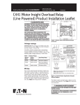
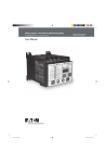
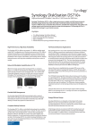
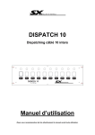
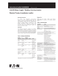
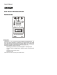
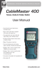
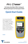
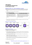
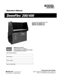
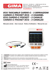
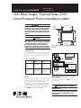
Installation Leaflet IL04209007E Effective May 2011 Supersedes May 2010 C441 Motor Insight™ Overload Relay (120V Control Powered) Product Installation Leaflet DANGER HAZARDOUS VOLTAGE CAN CAUSE ELECTRIC SHOCK AND BURNS. TO AVOID SHOCK HAZARD, DISCONNECT ALL POWER BEFORE ANY WORK IS PERFORMED ON THIS DEVICE. FAILURE TO DO SO WILL RESULT IN PERSONAL INJURY, DEATH OR SUBSTANTIAL PROPERTY DAMAGE 3.31 (84.1) 0.20 (5.1) 4 Places 3.50 (88.9) 3.90 (99.1) DANGER UNE TENSION ÉLECTRIQUE DANGEREUSE PEUT CAUSER DES CHOCS ÉLECTRIQUES ET DES BRÛLURES. POUR ÉVITER DES CHOCS ÉLECTRIQUES, DÉBRANCHER L’ALIMENTATION AVANT D’Y EFFECTUER DU TRAVAIL. L’INOBSERVATION DE CES INSTRUCTIONS ENTRAÎNERA DES BLESSURES CORPORELLES GRAVES, LA MORT OU DES DÉGÂTS MATÉRIELS SUBSTANTIELS. 3.90 (99.1) Figure 1. Mount with 10-32 Hardware Torque to 25 in-lb. Voltage Ratings Motor Insight overload relay is powered by 120V control power between X1 - X2. This voltage range for the various models is given in the following table. Table 1. Voltage Range 1 / L1 3 / L2 5 / L3 ATTENTION 1 A1 A2 CONTROL CIRCUITS ARE B300 RATED USE A CPT AND SEPRATATE CONTROL WHEN LINE VOLTAGE IS ABOVE 240VAC. 2/13 M 3/14 2/T1 4/T2 SEPARATE CONTROL 6/T3 CPT Nominal Rating 3- PHASE MOTOR INPUT 200 - 600 V Catalog Number Input Voltage Range C4410109NOUI C4410590NOUI 200 – 600 Vac; (50/60 Hz) +10% - 15% 120V L1 L2 C4410109NOUI C4410590NOUI 110 - 120 Vac; (50/60 Hz) +10% - 15% 95 96 97 98 X1 X2 R1 C" OVERLOAD RELAY R2 REMOTE PILOT DEVICES 2 WIRE CONTROL 3 1 NOT FOR USE WITH AUTO RESET OL RELAYS. T1 CONTROL POWER INPUT 110 - 120V L3 REMOVE WIRE C WHEN IT IS SUPPLIED. CONNECT SEPARATE CONTROL LINES TO THE NO. 1 TERMINAL ON THE REMOTE PILOT DEVICE AND THE TERMINAL 96 ON THE OVERLOAD RELAY. T2 T3 3 WIRE CONTROL START WHEN MORE THAN ONE PUSH BUTTON STATION IS USED OMIT CONNECTOR A AND CONNECT PER SKETCH BELOW. START A START 3 3 PHASE AC MOTOR STOP 2 1 3 STOP STOP 2 1 NOTE: X1, X2 - 120V Control Power Input. R1, R2 - 120V RESET INPUT Wiring Pass motor leads through Motor Insight overload relay CT pass through. If multiple passes of the motor leads are required, make sure that the current flow is from top to bottom through Motor Insight overload relay. If external CTs are used, pass the 5 amp secondary of the external CTs through Motor Insight overload relay internal CTs. See Table 3 for wrap and CT multiplier. Figure 2. Typical Starter Application Sample Wiring Diagram Motor Insight overload relay is factory set for manual reset operation. See Table 5 for automatic reset operation. WARNING AVERTISSEMENT AUTOMATIC RESET IS NOT INTENDED FOR TWO-WIRE CONTROL DEVICES. CE DISPOSITIF DE REENCLENCHEMENT AUTOMATIQUE NE CONVIENT PAS AUX COMMANDES À DEUX CONDUCTEURS. Installation Leaflet IL04209007E C441 Motor Insight™ Overload Relay (120V Control Powered) Product Installation Leaflet Effective May 2011 Terminal Connections Programming Set Points Motor Insight overload relay provides the following terminal connections. NC 95/96 contact is open when the device is unenergized. Motor Insight overload relay is easy to configure. Viewing and editing protection set points can be performed in the Protection and Operation Mode. The following steps outline the procedure for modifying any of the set points. USE 75°C CU WIRE ONLY * No Motor Loads, 9A Max 18-12 AWG Torque 0.6 Nm/5.3 lb-in. B300 PILOT DUTY ONLY 200VAC - 600VAC 3Ø 50/60 Hz L1 * L2 * L3 * NC 95 96 NO 97 98 120VAC 120VAC 120VAC CTRL PWR RESET X1 X2 R1 Step 1: Press Mode button until Protection or Operation Mode Led is lit. Mode Step 2: Press Up or Down button until the desired O/P LED is lit. Display shows the current parameter value. R2 110 Step 3: Press the Edit/Save button. The display now shows the parameter value but is now flashing. Figure 3. Terminal Connection Diagram 110 Edit/Save Table 2. Terminal Connection Specifications Name Designation Input Description Line Voltage L1, L2, L3 Line Voltage Three-phase line voltage input - L1, L2, L3 connections must correspond to the respective CT1, CT2, CT3 current leads. - Inputs must have short circuit protection - Terminal provided for wiring control power transformer (9A maximum capacity). Fault Relay 95/96 UL® 508 B300 - 95/96 Contact opens when the unit is faulted or unpowered. Programable Auxiliary Relay* 97/98 UL® 508 B300 -97/98 Contact closes when the unit is faulted or unpowered. Control Power X1 X2 UL 508 B300 110-120V control power input +10% / -15% Reset Input R1 R2 120 Vac +10%/-15% Fault Reset Input. * See section 6.7 of Users Manual MN04209001E for instructions to configure the programmable auxiliary relay, which changes the behavior of the relay from the default and allows for greater flexibility and alarming. CAUTION! THE OPENING OF BRANCH-CIRCUIT PROTECTIVE DEVICE MAY BE AN INDICATION THAT A FAULT HAS BEEN INTERRUPTED. TO REDUCE THE RISK OF FIRE OR ELECTRIC SHOCK, CURRENT-CARRYING PARTS AND OTHER COMPONENTS OF THE CONTROLLER SHOULD BE EXAMINED AND REPLACED IF DAMAGED. IF BURNOUT OF THE ELEMENT OF AN OVERLOAD RELAY OCCURS, THE COMPLETE OVERLOAD RELAY SHOULD BE REPLACED. ATTENTION LE DÉCLENCHEMENT DU DISPOSITIF DE PROTECTION DES DÉRIVATIONS PEUT SIGNIFIER QU’UN COURANT DE DÉFAUT A ÉTÉ INTERROMPU. POUR RÉDUIRE LE RISQUE D’INCENDIE OU DE CHOC ÉLECTRIQUE, LES PIÈCES PORTEUSES DE COURANT ET LES AUTRES COMPOSANTS DE LA COMMANDE DOIVENT ÊTRE VÉRIFIÉS ET REMPLACÉS S’ILS SONT ENDOMMAGÉS. SI L’ÉLÉMENT PORTEUR DE COURANT DU RELAIS DE SURCHARGE GRILLE, LE RELAIS DE SURCHARGE ENTIER DOIT ÊTRE REMPLACÉ. Initial Configuration On initial power-up, Motor Insight overload relay displays a “rOF” message. This indicates that the fault relay is OFF. Configure the device for the application prior to resetting the device. To turn the fault relay OFF, press the Trip button. 2 EATON CORPORATION www.eaton.com Step 4: Use the Up/Down button to adjust the parameter to the desired value. 120 Step 5: Press the Edit/Save button. The Display now shows the new parameter value that has been saved by the device. Edit/Save 120 Configuring the Thermal Overload Protection Feature Motor Insight overload relay features electronic motor overload protection. This feature protects the motor and power wiring against overheating caused by excessive current for extended periods of time. The trip current is programmed by entering the motor full load amperes (FLA) using the Motor FLA parameter. The trip class (5 to 30) is set using the Trip Class parameter. The FLA range of the overload relay can be modified with the use of multiple turns through the CTs or with the use of external CTs. Use the following tables to appropriately configure the device for the application. If the application requires the FLA range to be extended, program the CT multiplier first. Table 3A. FLA Range Current Range Catalog Number Motor FLA Number of Conductors Through CT CT Multiplier A (1 – 9 Amps) C4410109NOUI 1–5 2–9 60 – 135 120 – 270 240 – 540 2 1 1 1 1 2 1 150 - (150:5) 300 - (300:5) 600 - (600:5) B (5 – 90 Amps) C4410590NOUI 5 – 22.5 6.67 – 30 10 – 45 20 – 90 4 3 2 1 4 3 2 1 Important Note: After an overload trip, Motor Insight relay cannot be reset until the thermal model decays to a thermal capacity that is thermally safe for a motor restart. Cycling the power does not reset the thermal model. Table 3B. Service Factor FLA Setting Service Factor Motor FLA Setting >1.15 Enter the motor nameplate FLA =1.10 Enter the FLA as (1.1* nameplate FLA/1.15) Installation Leaflet IL04209007E C441 Motor Insight™ Overload Relay (120V Control Powered) Product Installation Leaflet Effective May 2011 Protection Set Point Summary Table Table 4 Protection Menu Set Points Type Jam Trip Threshold 50 – 400% of FLA Trip Delay ¹ 1 – 20 Seconds Current Unbalance 1 – 30% 1 – 20 Seconds Ground Fault 0.3 – 2.0 Amps (A) 3.0 – 20 Amps (B) 1 – 60 Seconds Phase Reversal 0 = Don’t Care 1 = ACB 2 = ABC 10 – 90% of FLA 2 Seconds (not adjustable) Under Current Low Power (kW) Default(s) 400% 2 Seconds 15% 10 Seconds 1 Amp (A) 10 Amps (B) 2 Seconds 1 = ACB 1 – 60 Seconds Notes This protection is disabled by default. See user manual for ranges when CT Multiplier is not set to 1. By default, the Phase Reversal fault is in alarm-no-trip mode. The MI fault relay will not close in a phase reversal condition. 1 – 60 Seconds 50% 5 Seconds 5 Seconds This protection is disabled by default. This protection is disabled by default. 1 – 60 Seconds 5 Seconds This protection is disabled by default. Overvoltage See User Manual For Ranges See User Manual For Ranges 170 – 660 1 – 20 Seconds Undervoltage 170 – 660 1 – 20 Seconds Voltage Unbalance 1 – 20% 1 – 20 Seconds 632 Volts 10 Seconds 216 Volts 10 Seconds 6% 10 Seconds By default, the overvoltage fault is in alarm-no-trip mode. The MI fault relay will not close in an overvoltage condition. By default, the undervoltage fault is in alarm-no-trip mode. The MI fault relay will not close in an undervoltage condition. By default, the Voltage Imbalance fault is in alarm-no-trip mode. The MI fault relay will not close in a voltage unbalance condition. High Power (kW) ¹ Trip delay settings can be adjusted using the Advanced Configuration Parameter. Operation Set Point Summary WARNING THE MOTOR INSIGHT OVERLOAD RELAY MAY RESET AT ANY TIME ENABLING A MOTOR START. WHEN FAULTED (FAULT LED IS ON), THE READY LED WILL FLASH WHEN AN AUTO RESET IS PENDING. AVERTISSEMENT LE RELAIS DE SURCHARGE MOTOR INSIGHT PEUT SE RÉINITIALISER À TOUT MOMENT PERMETTANT UN DÉMARRAGE DU MOTEUR. LORSQUE SE PRODUIT UNE DÉFAILLANCE (LE VOYANT DE DÉFAILLANCE DEL EST ACTIVÉ), LE VOYANT DEL « READY » CLIGNOTE LORSQU’UNE RÉINITIALISATION AUTOMATIQUE EST EN COURS. Table 5 Operational Menu Set Points Type Range Default(s) Motor FLA See Table 3 Trip Class Fault Reset Dly (m) 5 – 30 2 – 500 Minutes 2 Amps (A) 20 Amps (B) 20 8 Minutes Fault Reset (#) 0 – 4, A OL.1-OL.4, OL.A 1 Low kW Trip Dly (s) Load Reset Dly (s) 1 – 60 Seconds 2 – 500 Minutes or Automatic 5 Seconds 20 Minutes Load Resets (#) 0 – 4, A 1 Restart Delay Time 0 – 500 Seconds 10 Seconds CT Multiplier 1, 2,150, 300, 600 (A) 1, 2, 3, 4 (B) 1 – 247 1 Device Address Advanced Config Notes This is the delay after a motor fault (Thermal Overload, Jam, Current Unbalance). This timer inhibits a reset so that the motor can cool down. Number of auto-reset attempts after a motor fault. 0 = manual, A = auto, 1 – 4 = semi-auto. The Fault Reset (#) will be restored after the motor has been running for 15 minutes. The OL. prefix indicates that the setting applies to Overload trips, only. This is the delay after an undercurrent, low power, or high power trip. A = automatic – Load reset delays are computed based on previous motor run times. Number of auto-reset attempts after a load fault. 0 = manual, 1 – 4 = semi-auto, A = automatic. The Load Reset (#) will be restored after the motor has been running for 70 seconds. Inhibits a start after power-up. Useful when multiple motors are brought on-line at the same time. If using multiple turns or external CTs, this parameter must be configured appropriately. 1 See User Manual MN04209001E. EATON CORPORATION www.eaton.com 3 Installation Leaflet IL04209007E Effective May 2011 C441 Motor Insight™ Overload Relay (120V Control Powered) Product Installation Leaflet Fault Codes After a trip, Motor Insight overload relay will indicate the Trip reason with a Fault Code on the display and by illuminating the appropriate Protection/Operation (P/O) LEDs. Table 6. Fault Codes Fault Code User Interface Notes Mode LED P/O LED Display Number of Restarts Exceeded 1 Operation Fault Reset Tries & Load Reset Tries rEt Could result from excessive motor or load faults. Remote Off 2 None None rOF Relay turned off (network or UI). Voltage and current phase loss. Contactor Failure 3 Protection Current Unbalance % F.03 Low Power (kW) 15 Protection Low Power (kW) F.04 Motor Overload 5 Operation Trip Class F.05 Ground Fault 6 Protection Ground Fault (A) F.06 Current Unbalance 7 Protection Current Unbalance % F.07 Current Phase Loss 8 Protection Current Unbalance % F.08 F.10 Reserved 9 High Power (kW) 10 Protection High Power (kW) Overvoltage 11 Protection Overvoltage (V) F.11 Undervoltage 12 Protection Undervoltage (V) F.12 Voltage Unbalance 13 Protection Voltage Unbalance % F.13 Jam 14 Protection Jam Trip % F.14 Under Current 4 Protection Under Current % F.15 Phase Rotation 16 Protection Phase Rotation F.16 Current phase loss without voltage phase loss. Other Consult User Manual. Display Messages The following display messages may appear on Motor Insight overload relay user interface to indicate status. Table 7. Display Messages Message Description rOF The relay has been turned off. rSt The Restart Delay is timing down. Caution — an auto-reset attempt is pending. rEt The number of auto-resets attempts has been exceeded. A manual reset is required. ub A voltage imbalance has been detected. This message will flash with the displayed parameter in the alarm-no-trip mode. HI A high voltage condition has been detected. This message will flash with the displayed parameter in the alarm-no-trip mode. LO A low voltage condition has been detected. This message will flash with the displayed parameter in the alarm-no-trip mode. 1PH A voltage phase loss condition has been detected. This message will flash with the displayed parameter in the alarm-no-trip mode. gnd A ground fault condition has been detected. This message will flash with the displayed parameter in the alarm-no-trip mode. OFF The protection parameter is disabled. 999 The display parameter exceeds the display range. Eaton Corporation Electrical Sector 1000 Cherrington Parkway Moon Township, PA 15108 United States 877-ETN-CARE (877-386-2273) Eaton.com © 2009 Eaton Corporation All Rights Reserved Printed in USA Publication No. IL04209007E Rev005 May 2011 PowerChain Management is a registered trademark of Eaton Corporation. All other trademarks are property of their respective owners.