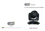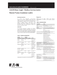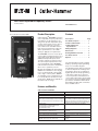
1
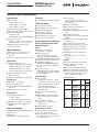
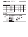
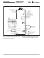
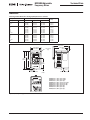
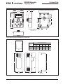
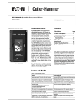
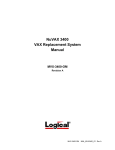
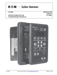
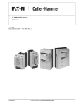
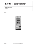
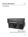
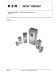
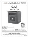
MVX9000 Adjustable Frequency Drives
Technical Data
Prices effective December 2004
MVX9000 Drives
Product Description
Cutler-Hammer® MVX9000 sensorless
vector adjustable frequency AC Drives
from Eaton’s electrical business are
designed to provide adjustable speed
control of three-phase motors. These
microprocessor-based, sensorless
vector drives have standard features
that can be programmed to tailor the
drive’s performance to suit a wide
variety of application requirements.
The MVX9000 sensorless vector product line utilizes a 32-bit microprocessor
and insulated gate bipolar transistors
(IGBTs) which provide quiet motor
operation, high motor efficiency and
smooth low speed performance. The
size and simplicity of the MVX9000
make it ideal for hassle free installation
where size is a primary concern.
Model MVX9000
Models rated at 480 volts, three-phase,
50/60 Hz are available in sizes ranging
from 1 to 10 hp. Models rated at 240
volts, single- or three-phase, 50/60 Hz
are available in sizes ranging from 1/2
to 7-1/2 hp. Models rated at 115 volts,
single-phase, 50/60 Hz are available in
the 1/4 to 1 hp size range.
Contents
Description
Page
Product Description . . . . . . . . . . . .
Features and Benefits . . . . . . . . . .
Technical Data and
Specifications . . . . . . . . . . . . . . .
Wiring Diagrams . . . . . . . . . . . . . .
Dimensions . . . . . . . . . . . . . . . . . .
Catalog Number Selection . . . . . .
Product Selection . . . . . . . . . . . . .
Options . . . . . . . . . . . . . . . . . . . . . .
1
1
2
3
5
6
8
8
The standard drive includes a digital
display, operating and programming
keys on a removable keypad.
The display provides drive monitoring
as well as adjustment and diagnostic
information. The keys are utilized for
digital adjustment and programming
of the drive as well as for operator
control. Separate terminal blocks for
control and power wiring are provided
for customer connections. Other features
provided as standard include built-in
DC braking, RS-485 serial communications and PID control.
Features and Benefits
Table 1. Features and Benefits
Feature
Customer Benefit
Sensorless Vector Control with auto tuning.
Provides 200% starting torque and advanced low
speed torque control.
Clearly laid out and easy to understand keypad
with 4-character LED display, 7 status indicating
LEDs, speed potentiometer, and 6 function keys.
Most informative operator’s interface in this
class of VFD, provided as standard. All parameters,
diagnostic information and metering values are
displayed with a bright 4-character LED display.
2 analog inputs
6 programmable, intelligent digital inputs
1 programmable digital output
1 programmable relay
Provide enhanced application flexibility.
PID control of a process variable such as pressure, Eliminates requirement for separate setpoint
flow, temperature, liquid level, etc.
controller.
TD04002001E
Built-in dynamic braking chopper.
Superior deceleration performance.
Serial communication port (RS-485).
Direct connection to serial communications
networks.
Single-phase or three-phase input capability on
240V AC rated units, 3 hp and below.
Operate three-phase motor with single-phase
supply.
For more information visit: www.EatonElectrical.com
Technical Data
Page 2
Effective: December 2004
MVX9000 Adjustable
Frequency Drives
Technical Data and Specifications
Output Ratings
Enclosure
■
■
■
■
■
■
■
Horsepower;
❑ 90V – 132V, 1/4 – 1 hp
❑ 200 – 240V: 1/2 – 7-1/2 hp
❑ 380 – 480V: 1 – 10 hp
Frequency Range: 0.1 – 400 Hz
Overload Rating: 150% for 60 seconds
Frequency Resolution:
❑ Digital: 0.1 Hz
❑ Analog: Max. (Set Frequency/1000) Hz
Frequency Accuracy
❑ Digital: ± 0.01% of max. frequency
❑ Analog: ± 0.2% of max. frequency
Undervoltage Carryover Limit:
0.3 to 25 seconds
Motor Performance
Protective Features
■
■
■
■
■
■
■
Motor Control: Sensorless Vector
■ Constant and Variable Torque:
Keypad
■
■
Standard
■
Speed Regulation: 0.5% of base speed
Input Power
■
■
■
Voltage at 50/60 Hz ± 3 Hz
❑ 100V – 120V, -10% +10% / 1-phase
❑ 200V – 240V, -10% +5% / 1-phase
❑ 200V – 240V, -10% +5% / 3-phase
❑ 380V – 480V, -10% +10% / 3-phase
■
■
Displacement Power Factor:
Better than 0.95
■ Efficiency: Typically greater than 95%
■
Microprocessor: 32-Bit
Converter Type: Diode
■ Inverter Type: Insulated Gate Bipolar
Transistor
■ Waveform: Sensorless Vector
■
■
Operating Temperature:
-10°C to +50°C
❑ -10°C to +40°C (above 7-1/2 hp)
■
■
❑
■
■
Humidity: 20 to 90% non-condensing
Maximum Elevation: 1000 meters
(3300 ft.)
Alphanumeric Display:
Standard, 1 x 4 character
Digital Indications:
Frequency (Hz), Motor Current
(amps), User-Defined RUN/STOP,
FORWARD/REVERSE and Parameters
Diagnostics: Last 3 trips with cause
LED Status Indicators: 8
(RUN/STOP, FORWARD/REVERSE,
Hz, Amps, User Defined, and Input
Speed)
Operator Functions:
START/STOP, Speed control (digital
or potentiometer), RESET, SETUP
Keys and ENTER.
I/O Terminal Block
■
Design Type
Environment
Ground Fault: Standard
Overload Protection: Standard
Overcurrent: Standard
Overvoltage: Standard
Undervoltage: Standard
Overtemperature: Standard
Overload Limit: Standard
Set Up Adjustments, Performance
Features, Operator Control and
External Interface
■
■
■
Analog Inputs:
❑ 2 Inputs: 0 – 10V DC, 4 – 20 mA
❑ Potentiometer: 1K ohm to 2K ohm
❑ Analog Voltage: Nominal 10V DC
(10K ohm input impedance)
❑ Analog Current: Nominal 4 – 20
mA (250 ohm)
Digital Inputs: 6 Programmable
Inputs
Digital Outputs: 1 Programmable
Open collector and 1 Form C Relay
contact
Analog Monitor Output:
❑ Analog meter – frequency or
output current
Dynamic Brake Chopper
Codes and Standards
Programmable Parameters
■
■
NEMA, IEEE, NEC: Design Standards
■ UL Listed
■ cUL Listed
■ CE Marked (Requires EMI filter)
■
Standard: Protected Chassis (IP20)
■
■
■
■
■
■
■
■
■
■
■
■
■
Auto Restart:
Overcurrent, overvoltage and
undervoltage with 4 selectable retry
restart modes
DC Injection Braking
External Fault: Terminal input
Jog: Terminal input
Fault Reset: STOP/RESET or terminal
input
I/O: NO/NC Selectable
Jump Frequencies: 3 (with adjustable
width)
Parameter Security: Programmable
software lock
Preset Speeds: 7 preset speeds
PID Controller: PID process control
Reversing: Keypad or terminal
Speed Setting: Keypad, terminal
or pot
START/STOP Control: Keypad or
terminal
Stop Modes: Decel, coast or DC
injection
Reliability
■
Pretested Components: Standard
Surface Mount Technology:
Standard (PCBs)
■ Computerized Testing: Standard
■ Final Test with Full Load: Standard
■ Eaton’s Cutler-Hammer Engineering
Systems and Service: National network of AF drive specialists
■
Table 2. Watts Loss
Horsepower Catalog
Number
Volts
Watts
Loss
9 kHz
1/4
1/2
1
MVXF25A0-1
MVXF50A0-1
MVX001A0-1
115V
AC
20W
20W
38W
1/2
1
2
3
5
7-1/2
MVXF50A0-2
MVX001A0-2
MVX002A0-2
MVX003A0-2
MVX005A0-2
MVX007A0-2
240V
AC
20W
38W
75W
110W
185W
275W
1
2
3
5
7-1/2
10
MVX001A0-4
MVX002A0-4
MVX003A0-4
MVX005A0-4
MVX007A0-4
MVX010A0-4
480V
AC
38W
75W
110W
185W
275W
375W
Out of the Box: Factory settings
loaded for quick start-up.
■ Accel. and Decel.: 2 separately
adjustable Linear or S Curve times:
0.1 – 3000 seconds
For more information visit: www.EatonElectrical.com
TD04002001E
MVX9000 Adjustable
Frequency Drives
Technical Data
Effective: December 2004
Page 3
Table 3. Dynamic Breaking Resistor Sizing
Dynamic Braking Resistors, Open Units
Catalog Number
Resistor
(Min. Ohms)
Watts
Braking
Torque
Duty
Cycle
115V
Series
K13-000034-0821
K13-000034-0821
K13-000034-0821
100
100
80
80W
80W
80W
220%
220%
125%
10%
10%
10%
1/2
1
2
3
5
7-1/2
230V
Series
K13-000034-0821
K13-000034-0821
K13-000034-0824
K13-000034-0824
K13-000034-0825
K13-000034-0826 100
80
55
35
25
16
80W
80W
300W
300W
400W
500W
220%
125%
125%
125%
125%
125%
10%
10%
10%
10%
10%
10%
1
2
3
5
7-1/2
10
460V
Series
K13-000034-0841
K13-000034-0843
K13-000034-0843
K13-000034-0844
K13-000034-0845 K13-000034-0846 260
190
145
95
60
45
80W
300W
300W
400W
500W
700W
125%
125%
125%
125%
125%
125%
10%
10%
10%
10%
10%
10%
Horsepower
Volts
1/4
1/2
1
Braking resister kit includes two resistors to be connected in parallel.
Braking resister kit includes three resistors to be connected in parallel.
Wiring Diagrams
RO3 RO2 RO1
DI1
DI2
DI3
DI4
DI5
DI6
COM AO+
AI1
+10V AI2 COM DO1 DOC
Factory Setting:
Inverter Running
NC Relay Output
Factory Setting:
Inverter Fault
NO Relay Output
4 – 20 mA
Bias
Potentiometer
Forward/Stop
Reverse/Stop
Preset Speed 1
Full Scale Voltmeter:
0 to 10V DC
Factory Setting:
Output Frequency
Preset Speed 2
Preset Speed 3
Reset
Figure 1. Control Terminal Wiring (Factory Settings)
TD04002001E
For more information visit: www.EatonElectrical.com
Digital Output
Technical Data
Page 4
MVX9000 Adjustable
Frequency Drives
Effective: December 2004
Braking Resistor
(Optional)
Main Circuit Power
L1
L2
L3
L1
L2
L3
B1
B2
T1
AC
Motor
T2
T3
Grounding Resistance
240V: Less Than 100Ω
480V: Less Than 10Ω
RO3
Factory
Default
Start/Stop
RO1
DI1
Reverse/Forward
Factory Default: Inverter Fault
NO Relay Output
(120V AC/24V DC 5A)
NC Relay Output
(120V AC/24V DC 5A)
RO2
DI2
Preset Speed 1
DO1
DI3
Preset Speed 2
Digital Output (48V DC 50 mA)
DI4
Preset Speed 3
DOC
DI5
Reset
Factory Default: Inverter Running
DI6
AO+
Common
COM
Analog Output
DC 0 to 10V
Reference Frequency Setting
Factory Default Is Potentiometer
Which Is on the Digital Keypad
3
2
Potentiometer
VR
3K – 5KΩ
1
COM
+10V 10 mA (Max)
RJ-11
AI1 (0 – 10V DC)
RS-485
Series
Interface
AI2 (4 – 20 mA)
6 to 1
Factory Default:
Output Frequency
1,6: NC
2: GND
3: SG4: SG+
5: +EV
COM
Main Circuit (Power) Terminals
Control Circuit Terminals
Shielded Leads
Figure 2. Basic Wiring Diagram
Note: Do not plug a modem or telephone line to the RS-485 communication port, permanent damage may result. Terminals 2 and 5 are
the power sources for the optional copy keypad and should not be
used while using RS-485 communication.
■
For single-phase application select correct model, and
select any of the two input terminals for main circuit
power.
For more information visit: www.EatonElectrical.com
TD04002001E
MVX9000 Adjustable
Frequency Drives
Technical Data
Effective: December 2004
Dimensions
Table 4. Approximate Dimensions and Shipping Weights for Basic Controller
Description
Horsepower
Dimensions in Inches (mm)
Shipping Weight
Lbs. (kg)
Volts
Width
Height
Depth
1/4
1/2
1
100 – 120
3.9 (100)
3.9 (100)
3.9 (100)
5.9 (151)
5.9 (151)
5.9 (151)
5.7 (145)
5.7 (145)
5.7 (145)
6.2 (2.8)
6.2 (2.8)
6.2 (2.8)
1/2
1
2
3
5
7-1/2
200 – 240
3.9 (100)
3.9 (100)
3.9 (100)
4.9 (100)
4.9 (125)
4.9 (125)
5.9 (151)
5.9 (151)
5.9 (151)
8.6 (220)
8.6 (220)
8.6 (220)
5.7 (145)
5.7 (145)
5.7 (145)
7.6 (193)
7.6 (193)
7.6 (193)
6.2 (2.8)
6.2 (2.8)
6.2 (2.8)
12.1 (5.5)
12.1 (5.5)
12.1 (5.5)
1
2
3
5
7-1/2
10
380 – 480
3.9 (100)
3.9 (100)
3.9 (100)
4.9 (125)
4.9 (125)
4.9 (125)
5.9 (151)
5.9 (151)
5.9 (151)
8.6 (220)
8.6 (220)
8.6 (220)
5.7 (145)
5.7 (145)
5.7 (145)
7.6 (193)
7.6 (193)
7.6 (193)
6.2 (2.8)
6.2 (2.8)
6.2 (2.8)
12.1 (5.5)
12.1 (5.5)
12.1 (5.5)
5.62 (142.7)
5.22 (132.5)
3.94 (100.0)
.18 (4.5) Dia.
Typ.
3.50 (89.0)
.39 (10.0)
5.94
(151.0)
6.34
5.51
(161.0)
(140.0)
3.35
(85.0)
MVX 9000
Sensorless Vector
HIGH VOLTAGE!
WAIT AT LEAST 5 MINUTES BEFORE OPENING.
SEE USER'S MANUAL FOR OPERATION.
.91
(23.0)
.55
(14.0)
.08
(2.0)
.39
(10.0)
1.77
(45.0)
MOTOR Braking
T1 T2 T3 B1 B2
MVXF25A0-1
MVXF50A0-1
MVX001A0-1
MVXF50A0-2
MVX001A0-2
MVX002A0-2
MVX001A0-4
MVX002A0-4
MVX003A0-4
(115V, 1 ph, 1/4 hp)
(115V, 1 ph, 1/2 hp)
(115V, 1 ph, 1 hp)
(240V, 1 ph /3 ph, 1/2 hp)
(240V, 1 ph /3 ph, 1 hp)
(240V, 1 ph /3 ph, 2 hp)
(480V, 3 ph, 1 hp)
(480V, 3 ph, 2 hp)
(480V, 3 ph, 3 hp)
Figure 3. 1/4 to 3 hp Drive Approximate Dimensions in Inches (mm)
TD04002001E
For more information visit: www.EatonElectrical.com
Page 5
Technical Data
Page 6
MVX9000 Adjustable
Frequency Drives
Effective: December 2004
7.55 (191.7)
7.15 (181.5)
4.92 (125.0)
.23 (5.8) Dia.
Typ.
4.33 (110.0)
.41 (10.5)
8.66
(220.0)
9.25
8.07
(235.0)
(205.0)
4.70
(119.5)
MVX 9000
Sensorless Vector
HIGH VOLTAGE!
WAIT AT LEAST 5 MINUTES BEFORE OPENING.
SEE USER'S MANUAL FOR OPERATION.
1.85
(46.9)
.59
(15.0)
MOTOR
T1
T2
T3
.59
(15.0)
.10 (2.5)
3.48 (88.5)
Braking
B1
B2
7.15
(181.5)
MVX003A0-2
MVX005A0-2
MVX007A0-2
MVX005A0-4
MVX007A0-4
MVX010A0-4
(240V, 1 ph /3 ph, 3 hp)
(240V, 3 ph, 5 hp)
(240V, 3 ph, 7-1/2 hp)
(480V, 3 ph, 5 hp)
(480V, 3 ph, 7-1/2 hp)
(480V, 3 ph, 10 hp)
Figure 4. 3 to 10 hp Drive Approximate Dimensions in Inches (mm)
Catalog Number Selection
M V X 0 0 1 A 0 - 2
Base Catalog
Number
Horsepower
F25 = 1/4 hp
F50 = 1/2 hp
001 = 1 hp
002 = 2 hp
003 = 3 hp
005 = 5 hp
007 = 7-1/2 hp
010 = 10 hp
Voltage
Series
A
1 = 115V AC
2 = 240V AC
4 = 480V AC
Enclosure
0 = IP20
For more information visit: www.EatonElectrical.com
TD04002001E
MVX9000 Adjustable
Frequency Drives
2.54 (64.6)
2.36 (60)
1.20
(30.5)
Technical Data
Effective: December 2004
.08
(2.0)
.09 (2.3) Dia. x .19 (4.8) Deep Connection Hole
for Extension Cable Screw (Typ. 2 Places)
.92
(23.3)
3.46
(88)
1.63
(41.5)
2.22
(56.5)
1.81
(46)
1.48 (37.6)
M4 P .03 (.7) x .19 (4.8) Deep
for Mounting Screw
(Typ. 3 Places)
Figure 5. Digital Keypad Approximate Dimensions in Inches (mm)
Enclosure
Frame
Approximate Dimensions
in Inches (mm)
H
W
9.7
4.2
MVXENCS
(246.4) (106.7)
5.2
MVXENCL 12.8
(325.1) (132.1)
D
H1
5.7
8.2
(144.8) (208.3)
7.4
11.0
(188.0) (279.4)
H2
W1
.8
(20.3)
1.0
(25.4)
2.1
(53.3)
2.6
(66.0)
Top View
H1
H
H2
W
Front View
D
Side View
W1
Back View
Figure 6. MVX9000 NEMA 1 Enclosure
TD04002001E
For more information visit: www.EatonElectrical.com
Page 7
Technical Data
Page 8
Effective: December 2004
MVX9000 Adjustable
Frequency Drives
Product Selection
Table 6. Field Options Kits (Continued)
Description
Catalog Number
3% Line Reactor, 3-phase
1 hp, 480V
2 hp, 480V
3 hp, 480V
5 hp, 480V
7-1/2 hp, 480V
10 hp, 480V
K64-000989-2091
K64-000989-4091
K64-000989-4091
K64-000989-8091
K64-000989-0180
K64-000989-0250
Table 5. MVX9000 Basic Controller IP20
Description
Horsepower
Volts
Input Ampere
Single-/
Three-Phase
Rating
MVXF25A0-1
MVXF50A0-1
MVX001A0-1
6.3/2.9
11.5/6.3
15.7/8.8
27.5/12.5
—/19.6
—/31.5
2.5
5.0
7.0
10
17
25
MVXF50A0-2
MVX001A0-2
MVX002A0-2
MVX003A0-2
MVX005A0-2
MVX007A0-2
—/4.2
—/5.7
—/7.0
—/8.5
—/14
—/20.6
3.0
4.0
5.0
8.2
13
18
MVX001A0-4
MVX002A0-4
MVX003A0-4
MVX005A0-4
MVX007A0-4
MVX010A0-4
90 –
130
6.3/—
9.0/—
18.0/—
1/2
1
2
3
5
7-1/2
200 –
240
1
2
3
5
7-1/2
10
380 –
480
Catalog
Number
1.6
2.5
4.2
1/4
1/2
1
Continuous
Output
Amp Rating
Horsepower ratings are based on the use of a 240V or 480V NEMA B,
4- or 6-pole squirrel cage induction motor and are for reference only.
Units are to be selected such that the motor current is less than or
equal to the MVX9000 rated continuous output current.
For 208V, 380V or 415V applications, select the unit such that the motor
current is less than or equal to the MVX9000 rated continuous output
current.
Options
Table 6. Field Options Kits
Description
Catalog Number
Keypads
Copy Keypad
Normal Keypad
Remote Kit
MVXCOPY
MVXKPD
MVXRM
Miscellaneous Options
Extension I/O
DIN Rail
MVXEIO
MVXDR
Communications
DeviceNet Module
MVXDN
NEMA 1 Enclosure
Small Frame
Large Frame
MVXENCS
MVXENCL
3% Line Reactor, 1-phase
1/2 hp, 240V
1 hp, 240V
2 hp, 240V
3 hp, 240V
K64-000988-8091
K64-000988-0120
K64-000988-0180
K64-000988-0250
1/2 hp, 240V
1 hp, 240V
2 hp, 240V
3 hp, 240V
5 hp, 240V
7-1/2 hp, 240V
K64-000988-2091
K64-000988-4091
K64-000988-8091
K64-000988-0120
K64-000988-0180
K64-000988-0250
Output Line Reactor
1 hp, 480V
2 hp, 480V
3 hp, 480V
5 hp, 480V
7-1/2 hp, 480V
10 hp, 480V
K64-000989-2091
K64-000989-4091
K64-000989-4091
K64-000989-8091
K64-000989-0120
K64-000989-0180
EMI Filter
1/2 hp, 240V AC, Single-Phase
1 hp, 240V AC, Single-Phase
2 hp, 240V AC, Single-Phase
3 hp, 240V AC, Single-Phase
K13-000034-0111
K13-000034-0111
K13-000034-0111
K13-000034-0112
1/2 hp, 240V AC, Three-Phase
1 hp, 240V AC, Three-Phase
2 hp, 240V AC, Three-Phase
3 hp, 240V AC, Three-Phase
5 hp, 240V AC, Three-Phase
7-1/2 hp, 240V AC, Three-Phase
K13-000034-0113
K13-000034-0113
K13-000034-0113
K13-000034-0113
K13-000034-0115
K13-000034-0115
1 hp, 480V AC, Three-Phase
2 hp, 480V AC, Three-Phase
3 hp, 480V AC, Three-Phase
5 hp, 480V AC, Three-Phase
7-1/2 hp, 480V AC, Three-Phase
10 hp, 480V AC, Three-Phase
K13-000034-0114
K13-000034-0114
K13-000034-0114
K13-000034-0116
K13-000034-0116
K13-000034-0117
Dynamic Braking Resistor
1/2 – 1 hp, 240V
2 – 3 hp, 240V
5 hp, 240V
7-1/2 hp, 240V
K13-000034-0821
K13-000034-0824
K13-000034-0825
K13-000034-0826
1 hp, 480V
2 – 3 hp, 480V
5 hp, 480V
7-1/2 hp, 480V
10 hp, 480V
K13-000034-0841
K13-000034-0843
K13-000034-0844
K13-000034-0845
K13-000034-0846
Eaton Electrical Inc.
1000 Cherrington Parkway
Moon Township, PA 15108-4312
USA
tel: 1-800-525-2000
www.EatonElectrical.com
© 2004 Eaton Corporation
All Rights Reserved
Printed in USA
Publication No. TD04002001E/CPG
December 2004