1
Does the reference manual actually describe the real computer?
Not entirely, but the authors, starting with a simulation based on
the written word, worked out the, remairning errors using the
machine diagnostics as the last word.
Using Emulaion to Verify
Formal Architecture Descriptions
Mario R. Barbacci
Carnegie-Mellon University*
Alan Parker
Naval Research Laboratory
Formal descriptions of digital systems have been
used mainly for academic purposes.' A recently
completed project, however, illustrates that such
descriptions are highly useful in the evaluation of
commercially available computer architectures. A
formal description can serve as the specification of
a family of architectures. Such a specification, to be
of value, must accurately reflect the actual architecture. Verification of this relationship, therefore, is
central to the description's usefulness as a specification. Once verified, the description can generate
machine- and implementation-independent diagnostics to be used in the evaluation of any architecture claiming family membership.
The Computer Family Architecture Project2
evaluated a set of commercially available architectures in order to select a standard family of tactical military computers. Three of these architectures (IBM S/370, Interdata 8/32, and DEC PDP-11)
were selected for a detailed comparison via test
programs executed under an instrumented simulator. The results of the experiment, together with an
evaluation of the existing software bases, were used
to select the PDP-11 as the preferred architecture.
A simulator and associated tools were used to
verify the description of the selected architecture.
Although the PDP-11 is the only architecture used
in this article, the method is general and can be
applied to other (not necessarily existing) computer
architectures.
Since formal descriptions have been used mostly
for academic purposes,2 the use of ISP345 in the
CFA Project was, to our knowledge, the first time
descriptions of real, commercially available architec*Currently on leave at Digital Equipment Corporation.
May 1978
tures were used for evaluation and verification.
Other projects show a range of applications of formal
descriptions well beyond what will be described in
this article.678
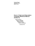
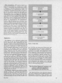
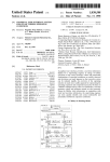
The architecture research facility
The architecture research facility used in the
CFA Project and later in the verification of the
PDP-11 description is depicted in Figure 1. The ISP
compiler produces code for a hypothetical machine,
dubbed the "Register Transfer Machine." The
"object code" produced by the compiler can be linked
together with a program capable of interpreting
RTM instructions. This separation between the
architecture description, the RTM code, and the
RTM interpreter allows the simulation of arbitrary,
user-defined architectures. Linking the RTM code
with the RTM interpreter results in a running
program, a simulator of the target architecture.
The simulator accepts commands from a terminal
or user-designated command file. The status of the
simulator can be dumped on a file which can be
read later when the simulation is to continue. Command files can also be used to load programs and
data into the simulated target-machine memory
and registers.
The latter facility constitutes the single most
important feature of the command language. Benchmarks during the CFA Project and diagnostics
during the verification phase were assembled and
translated into absolute numeric code, in a format
compatible with the simulator command-language
interpreter. Once the target machine has been so
initialized, programs can be executed by starting
0018-9162/78/0500-0051$00.75 (D 1978 IEEE
51
Figure 1. Test program execution under the Architecture
Reseach Facility.
the instruction interpretation cycle, described as an
ISP procedure. Tracing registers and setting breakpoints provide the basic mechanisms for testing
and debugging both users' programs and architectures. Event counters are used to gather data for
performance monitQring and evaluation. Users can
enable or disable these counters.
Two ARF's were used during verification. These
were developed at Carnegie-Mellon University and
the Naval Research Laboratory as independent
efforts. Both systems use very nearly the same
command language so that test procedures were for
the most part compatible between them. The diagnostics were executed using both simulators, thereby increasing our confidence in the results.
Verification of a computer description
Using formal descriptions of computer architectures for design, evaluation, and software development invariably leads to the following, question:
How correct is the description? The answer lies in
How correct is the architecture
description?
the source of information used to prepare the description. All manufacturers provide a "principles
of operations" manual to aid programmers. This
manual is supposed to contain the true specification
52
of the architecture. Unfortunately, the quality of
these informal specifications varies. By far the best
documentation on the architectures under consideration is provided by IBM, and the least complete by
Interdata. Within IBM, the description of the architecture is contained in a single document.9 DEC
provides several manuals, one for each model, which
require alternating between manuals when details
are not clear. The description of the Interdata 8/32
required consultation with the manufacturer, and
some of the information was not guaranteed to be
valid for later models. Even if complete manuals
are available, there is always the possibility that
one's interpretation of the English definition of the
architecture differs from that of the implementer.
This ambiguity leads to the need for verifying the
architecture description.
In order to place our work in perspective, we
will refer to the work performed by Carter and
others at IBM.10 Carter approaches the problem
of validating computer designs by proving the
correctness of microcode. A computer's design
is considered to be correct when programs written
according to the specifications run, and the desired
results are obtained.
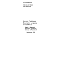
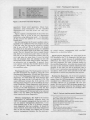
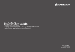
This view of verification can be applied throughout the stepwise refinement of a computer's design,
as shown in Figure 2. At the top level (1), the
instruction set processor description is the specification and the programs are sequences of microinstructions interpreted by a more primitive processor (2).
The latter constitute a specification for the behavior
of a register transfer network (3). Programs in this
context are the state transitions. At some point the
refinement process is completed and manufacturing
specifications are generated ('wiring lists'). As
building blocks are connected together to build
larger modules (4,5,6), a correspondence exists
between the abstract and the physical levels of the
system. In the context of this figure, Carter's work
verifies the correctness of the transition from (1) to
(2) by proving that, given the same initial state, two
sequences of instructions, S and micro-S, compute
identical results. The objective is to answer the
question: does micro-S simulate the actions of S?
The object of our project was to attempt to answer
the following question: Given a sequence of instructions (a program) that compute some results in the
physical machine (6), and a set of abstract instructions descriptions (1), does the abstract machine
simulate the actions of the physical machine? The
rationale behind our definition of the term verification is the following: The CFA Project selected an
architecture for a family of machines with different
cost/performance tradeoffs. These machines will be
built by different manufacturers after bidding for
contracts for each of the models. In order to
guarantee the compatibility (family membership) of
these models, a formal description of the archxitecture will be part of the procurement documentation.
Thus, the formal specification of the architecture
must be certified to be a description of the PDP-11
architecture.
COMPUTER
Model dependencies. ISP can be viewed as a
programming language for a specific class of algorithms, i.e., instruction sets or architectures. Ideally,
a language to describe architectures should avoid
the specification of any implementation details. Any
components introduced beyond these are unnecessary for the machine programmer and might even
bias the implementer working from the description.
Although these items must appear in a description
of the implementation, the abstractions and/or algorithms may vary across members of the family when
describing a family of machines. Some model dependencies creep into the implementation and are not
detected or documented by the manufacturers.
Finally, model dependencies are sometimes introduced by design, and the user is in fact given
separate manuals describing the different members
of the family. The DEC PDP-11 family is a clear
example of the latter type of model dependencies.
Each processor of the family comes with a user's
manual describing the instruction set. The CFA
selection committee decided early in the project to
adopt the PDP-11/70 instruction set as the specification of the PDP-11 family architecture. This
decision affected the formal description of the architecture in two key areas: memory management and
floating point instruction set.
Diagnostics
Our approach to the verification problem does
benefit from the fact that physical implementations
of the architecture under consideration do exist.
Therefore, a large set of programs developed for the
PDP-11 can be used in the verification of the ISP
description. In particular, we were interested in a
class of programs that purport to exercise all the
features of the machine, namely the diagnostic
programs used for maintenance of the central processor. Diagnostics have the added advantage of
including the comparison of the computation with
known results, thus narrowing down the identification of errors and speeding the debugging process.
We had two types of diagnostic programsfunctional and micro-level. The functional diagnostics test each machine instruction using each addressing mode. These programs execute the instructions
with known data and check the results and the
condition code settings. The micro-level diagnostics
make use of microcoded test breakpoints and test
operations on the. data path level. Presumably this
makes for a better check of the machine, but since
micro-level diagnostics assume knowledge of the
implementation of the architecture, they were not
suited for our use. The functional diagnostics were
well suited for us, however.
The diagnostic programs were studied and edited.
Sections dealing with implementation-dependent
details were removed. Since these diagnostics were
intended for the 11/40 and the 11/45, care was exercised to use only tests of instructions that were
specified to behave the same on these models as on
May 1978
Figure 2. Design steps.
the 11/70. This set covers most instructions since
the main difference lies in the memory management.
The diagnostics require a console terminal to be
attached to the system. Some diagnostics require
disk or tape units. Since none of these devices exist
on the architecture research facility, the diagnostics
had to be modified to operate without any I/O
devices. This was quite easy to do. In their original
form the diagnostics would print a message on the
console if an error was detected. We simply modified
them to halt (execute the PDP-11 HALT instruction)
if an error was detected. Such a halt was located in
every instruction's test routine, so if a halt did
occur its address would correspond to the particular
PDP-11 instruction being tested.
The functional diagnostic program was
used to verify the simulator's
description of the architecture.
The selected portions of the diagnostic programs
were used to produce 22 test programs for the nonfloating-point instructions. These programs were
used to test the unary word operations, unary byte
53
Table 1. Floating-point diagnostics.
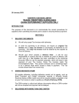
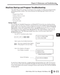
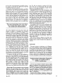
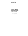
Figure 3. Decrement instruction diagnostic.
operations, binary word operations, binary byte
operations, jump instructions, and the extended
instructions (SXT, XOR, SOB, MARK, ASH, ASHC, MUL,
and DIV).
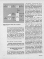
Figure 3 shows a small portion of one of the test
programs. This is a test of the DEC (decrement)
instruction using addressing mode 1. In this example R2 contains the address of a word containing
sample data.
For this instruction the C (carry) condition code is
specified to be unaffected. The test program set the
C bit and, after the instruction execution, verified
that it was still set. The V (overflow) bit should
have been set by this operation because it is specified
to be set if the initial value of the data was 100000
(octal). The BLE (branch less than or equal) checks
that both the N (non-zero) and V bits are not set.
The test for the next instructions follows after the
HALT and takes the same form. It must be noted
that the program does not attempt to test the
instructions with a wide range of data. Obviously,
an exhaustive test is impossible. In general, these
tests operate with data that borders between negative and positive. This practice tends to exercise
the conditions codes.
Floating-point tests. The floating-point section of
the ISP description was tested by using the 11/45
floating-point diagnostics. (We did not have access
to the 11/70 floating-point diagnostics.) With these
diagnostics, we could check only those features that
behave the same on the 11/45 and the 11/70. The
major difference between the 11/45 and the 11/70
floating-point processor is in the handling of exceptional conditions. These diagnostics were edited to
produce six test programs for the floating-point
section of the ISP description. As with the first
set of diagnostics, implementation-dependent details
such as timing and I/O devices had to be removed.
Table 1 lists the PDP-11/70 floating-point instructions tested with these diagnostics.
Memory management. The PDP-11/70 memory
management is sufficiently different from the
PDP-11/45 memory management that we could not
use our memory management diagnostics. A machine-readable copy of the 11/70 memory management diagnostic was not available. It should be
noted, however, that some of the other diagnostics
that we did run made very limited use of some
memory management features. For the most part,
54
CFCC (copy floating condition codes)
LDD, STD, CMPD of a four word item of -1,0. -1,0
LDD, STD, CMPD of a four word item of 0, -1.0, -1
LDF, STF, CMPF of a two word item of -1,0
CMPF, TSTF, TSTD
CLRX, ABSX
LDEXP, STEXP
ADDF, SUBF, ADDD, SUBD
MULF, DIVF. MULD, DIVD
LDCFD, LDCDF, STCFD, STCDF
LDCIF, LDCID. STCFI, STCDI
LDCLF, LDCLD, STCFL, STCDL
MODF, MODD
LDD of -O
MULF with overflow error
DIVF with overflow error
STCFI conversion error
Divide by zero error
LDF of -0
Opcode error
ADDF with overflow error
SUBF with underflow error
ADDD, SUBD conversion error
LDD, STD
we tested memory management with non-DEC
diagnostics, as described below.
Special purpose diagnostics. For some parts of the
ISP description the 11/45 diagnostics we had were
not appropriate, mainly because of model-dependent
differences. For these cases we had to write our
own test programs. We used a format similar to
the machine diagnostics. An action was caused and
the state of the simulated machine architecture was
checked. If the state was not as predicted, then a
PDP-11 HALT instruction was executed to stop the
simulation. Table 2 lists those portions of the ISP
description for which test programs were written.
Running the diagnostics. AU of the test programs
were written in standard PDP-11 assembly language. Since the ISP description is maintained and
simulated on a DECsystem-10, we used a crossassembler (MACY-11) to assemble the test programs. We also used a CMU-developed program to
format the assembler output for the simulator. This
program, called Slink, functions as a linkage editor
Table 2. Features requiring special diagnostics.
RTI and RTT (return from interrupt and trap)
MFPI, MFPD, MTPD, MTPI (move from/to previous space)
Memory Management Register 1 actions
Memory Management Page registers and relocation actions
Memory Management Page length errors
PIR (program interrupt register)
Stack Limit
JMP and JSR with address mode 0 (it is illegal)
LDEXP (floating point load exponent)
Check of general register set for undesired interactions
COM PUTER
tion. We will not attempt to analyze all of these
errors here, but we will discuss this last group
since it is the most interesting in terms of our
architecture specification work.
The original writer of the ISP description'" used
the PDP-11 processor manuals as the definition of
the instructions.12'3'4 If the manuals were vague
about a particular point, then the ISP writer had
no choice' but to make a decision' on how to describe
that feature. The description of the feature could
therefore vary from the real machines i,n some way.
The diagnostics expect the instructions to behave
as implemented'by DEC, so our ISP simulation
would fail to properly execute the test program.
In fact, for several features of the architecture the
diagnostics provide a better statement of the architecture than the processor manual.
An example of this is the ASHC (arithmetic shift
The most interesting errors were those
combined) instruction. The processor manual states
that resulted from lack of clarity in
that the V condition code bit is set if the sign bit
the architecture documentation.
changes during the shift. The writer of the ISP
description interpreted this to mean that the V bit
This rarely happened, and most tests took a few should be set if the sign of the final result is difseconds to execute. A breakpoint the simulator ferent from the sign of the initial value. Actually,
could hit includes execution of the PDP-11 HALT the V bit should be set if the sign bit changes at
instruction, or an error condition in the ISP descrip- any time during the shift operation (to indicate
tion simulation. Such errors include illegal branches, overflow). In this case the diagnostic provided us
divide-by-zero attempts, illegal shifts, and overflows. with a clear definition of this feature. There were
Any of these conditions indicate an error in the ISP other similar errors.
Most errors, however, belong to the other catedescription. If the HALT instruction was executed,
and were omissions, such as failure to set a
gories
it was then necessary to determine the address
code or write the result of an operation to
condition
(within the'simulated architecture's address space)
of the halt. This was done simply by examining the memory.
program counter. This address was used to refer to
the assembly listing of the test program to determine if it was the normal end of the program or an Conclusion
error indication. The test programs have one normal
The main criterion in selecting a set of diagnosHALT, indicating the end, and many abnormal
HALTs, indicating errors detected. Usually there is tics or test programs is the coverage they provide.
one HALT for each possible error within a test pro- In this sense, we cannot offer proof of completeness;
gram. If we found that the halt executed was the we worked, for the most part, with existing pronormal end of the test program, then we marked grams and accepted them as given. A secondary
that program as having been executed successfully assumption is, of course, that the test programs
work, i.e., they test the features they were intended
and went on to the next test program.
If, however, the halt was an error indicator or for (as it turns out, our experience has shown that
one of the error breakpoints occurred, then it was even this assumption cannot be taken for granted).
necessary to locate the error in the ISP description.
The ARF commands were used to examine the state
Implementation-independent diagnostics
of the simulated machine, i.e., the general registers,
the program counter, and memory. The test promay certify new models based on
grams could be restarted with tracing activated.
PDP-11 architecture.
This provides a routine trace within the ISP
description itself and also allows selected register
The use of two separate simulators gave us some
values to be monitored as their value changes.
degree of confidence in the machinery used (the RTM
Most errors were detected and fixed within an hour.
interpreter). The use of a large number of programs
Errors found. The test programs were run between (the CFA test programs and the diagnostics) written
February 1977 and October 1977 at NRL. Running by a large number of programmers, with different
these test programs revealed about 50 errors in the degrees of experience, increased our confidence in
ISP description. These errors fit into several cate- the ISP description as a true specification of the
gories: typographical or clerical errors, simple omis- PDP-1 1 architecture.
Current work by Oakley7 attempts to improve the
sions or oversights, and errors caused by misunderstanding or lack of clarity in the DEC documenta- coverage by automatically generating the diagnos-
and can link several separately assembled routines.
Its output is a file that the ARF uses to load the
simulated architecture's memory.
To execute a test program we needed to assemble,
link, and load it into the simulator. Simulator commands were used to set the simulated machine's
program counter (R7 on the PDP-11) to the starting
address of the test program. All of the test programs
execute without requiring any outside data or in'tervention. The test program was then allowed to'execute until the simulation hit a breakpoint or a time
limit passed. If the time limit passed-usually
three minutes of CPU time-then the simulator's
program counter was monitored as it changed to
determine if the test program was in an endless loop.
May 1978
55
tics from an ISP description. Oakley's problem is
therefore to generate programs which, when executed on the- physical machine, will reproduce the
results of their execution on the abstract machine,
i.e., does the physical machine simulate the abstract
machine? Since the ISP description of an architecture is free from implementation details, it in fact
describes a family of machines, namely all those
machines whose instruction sets include the architecture described in ISP. Automatically generated
diagnostics will be useful when multiple manufacturers build the different members of a family.
Running these implementation-independent diagnostics can be used as part of a certification procedure by which newer models are accepted as
members of the family. U
7.
J. Oakley, "Automatic Generation of Diagnostics
from ISP." PhD Thesis Proposal, Department of
Computer Science, Carnegie-Mellon University, 1976.
8.
J. D. Wick, "Automatic Generation of Assemblers,"
PhD Thesis, Department of Computer Sciences, Yale
University, 1975.
9.
IBM System/370 Principles of Operation, IBM
Corp. Form GA22-7000-4.
10. W. C. Carter, "Experiments in Proving Design
Correctness for Micro-program Validation," Digest
Int. Symp. Fault Tolerant Computing, Champaign,
June 1974, pp. 5.22-5.27.
11. A. Parker, "A Guide to the PDP-11 ISP Description," Naval Research Laboratory, Technical Memorandum 5403-232, November 1977.
12. PDP-11/70 Processor Handbook, Digital Equipment
Corporation, Maynard, Massachusetts.
Acknowledgements
Dan Siewiorek of Carnegie-Mellon University
wrote the initial ISP description of the PDP-11/45
which predated the CFA Project. He later helped
upgrade the description to the PDIP-11/70 level.
Ivor Durham (CMU) updated the floating-point
instruction set to the PDP-11/70. Gregory Lloyd and
Honey Elovitz of the Naval Research Laboratory participated in the initial phases of the
verification effort. Lloyd Dickman of DEC helped
clarify details of the architecture and served as a
contact with the designers and implementers of the
PDP-11 family.
References
56
1.
M. R. Barbacci, "A Comparison of Register Transfer
Level Languages for Q)escribing Computers and Other
Digital Systems," IEEE-TC, Vol. C-24, No. 2,
February 1975.
2.
B. Wald and A. Salisbury (guest editors). "Military
Computer Architectures: A Look at the Alternatives," Computer, Vol. 10, No. 10, October 1977,
pp. 8-63.
3.
C. G. Bell and A. Newell, Computer Structures:
Readings and Examples, McGraw-Hill Book Company, New York, 1971.
4.
M. R. Barbacci, The ISPL Compiler and Simulator
User's Manual, Technical Report, Computer Science
Department, August 1976.
5.
M. R. Barbacci, G. E. Barnes, R. C. Cattell, and
D. P. Siewiorek, The ISPS Computer Description
Language, Computer Science Department, Technical
Report, Carnegie-Mellon University, August 1977.
6.
R. G. Cattell, "Formalization and Automatic Derivation of Code Generators," PhD Thesis Proposal,
Department of Computer Science, Carnegie-Mellon
University, 1977.
13. KB11-B Flow Diagrams, Digital Equipment Corporation, Maynard, Massachusetts.
14. FP11-C Flow Diagrams, Digital Equipment Corporation, Maynard, Massachusetts.
MM Mario R. Barbacci is a research
computer scientist with the Department of Computer Science at Carnegie-
Mellon University, currently on leave
of absence with the R&D group at
Digital Equipment Corporation. His
research interests include computer
architecture, automatic programming,
and design automation. Barbacci
^
:A Zreceived the BSEE and engineer
degrees from the Universidad Nacional de Ingenieria,
Lima, Peru, in 1966 and 1968, respectively, and the
PhD from Carnegie-Mellon University in 1974. He is a
member of the ACM and Sigma Xi, and a senior member
of the IEEE.
Robert Alan Parker is a member of
the Information Systems Staff of the
Communication Sciences Division at
l | the Naval Research Laboratory in
ffin,
NM~~
Washington. He has been involved
| with the Military Computer Family
-project since 1975. He received the
BS degree in computer science from
the University of Maryland in 1975.
COMPUTER


![取扱説明書 [PDF形式]](http://vs1.manualzilla.com/store/data/006695527_2-b464c3ee3b4c6314b2db50de5091d527-150x150.png)