1
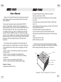
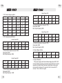
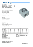
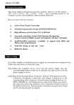
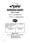
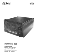
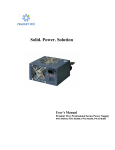
User's
Manual
Huntkey Hong Kong Development Co.,Ltd.
Address: Huntkey Industrial Park, Banxue Road,
Bantian, Shenzhen,518129, China
Tel: +86-755-8960 6658
Fax:+86-755-8960 6699
Website:www.huntkeydiy.com
E-mail:[email protected]
PSU
PSU
Thank you for choosing this Green Power series power supply unit
(PSU)! Please read this manual carefully and follow its instructions
before installation.
Green power series power supply complies with Intel ATX12V
Version 2.3 specifications. It includes a 6 pin PCIe connector for
high-end graphic card and 4+4 pin connector (500W&550W) for Dual
Core CPU and Multi Core CPU. Dual +12V rails deliver safer and
more reliable output to your system. The standby mode consumes
less than 1W when +5VSB is less than 0.1A. It saves more energy
and your money. In addition we've included a variety of industrial-grade
protective circuitry: OCP (Over Current Protection), OPP (Over Power
Protection), OVP (Over Voltage Protection), SCP (Short Circuit
Protection).
We would like to draw your attention to the conditions that your
system works best for you without failing. To avoid such failures and
to increase lifetime of your entire system, we suggest you to make
sure that:
.Your PC or server is not located near a radiator or any other heat
producing device
.Your PC or server is not located near a magnetic device
.Your PC or server is not located in a moist or dusty or vibrating
environment
.Your PC or server is not exposed to direct sunshine
.Your PC or server must be work at stable input AC voltage
Chapter A: Features
.Complies with Intel ATX12V V2.3
.80% high efficient performance at typical load operation.
.Ultra low acoustic noise (≤25dB)
.SLI Ready and supports Intel & AMD Dual Core CPUs and Multi
Core CPUs
.The standby mode consumes less than 1W when +5VSB is less
than 0.1A.
.Higher reliability and built-in protection circuit OCP, OVP, OLP, SCP
and line input fuse protection.
.6 pin PCIe provides more power for graphic card
.4+4 pin connector for Dual Core CPU and Multi Core CPU
.FAN speed auto-controlled by thermal sensor in the side of power
supply
.100% Hi-pot and burn-in test
.MTBF: 100,000 hours at 25℃
To make sure you connect your power supply properly, please
check your main board and graphics card manuals for compatibility
before connecting the power supply to any of your devices.
Outp ut
cabl e
86 .0 0
User's Manual
150
.00
140
.00
12cm FAN
VOLTAGE SWITCH
AC INPUT
POWER SWITCH
Dimension: 150×86×140 mm (W×H×L) 12cm Fan
01
02
PSU
PSU
86 .0 0
O ut p ut
c ab l e
150
.00
160
.00
14cm F AN
V O LTA G E SW I TC H
AC INPUT
POWER SWITCH
Dimension: 150×86×160 mm (W×H×L) 14cm Fan
Chapter B: Installation
1.Turn off your computer; unplug the power cord from your old
power supply.
2.Open your computer case following your case manual.
3.Disconnect all PSU connectors from the motherboard and the
peripherals, such as cooler, HDD, DVD, CDR, FDD, etc.
4.Remove the old power supply from your computer case and install
your new power supply.
5.Connect the 20+4 pin main power connector to your motherboard.
Note: Use the separated 20 pin if your motherboard requires 20 pin
power connector.
6.Connect the Serial-ATA connectors to the peripherals.
7.Connect the peripheral 4 pin power connectors if you are still using
IDE hard drives or optical drives.
8.Connect the PCI EXPRESS power connector to your PCI EXPRESS
graphic card.
03
9.Connect your cooler to the regular 4 pin peripheral connectors if
you have.
10.Close your computer case and connect the AC power cord to the
power supply.
Chapter C: Booting the system
1.Main power connector (24 pin configuration) is properly connected
2.CPU +12V power connector (4 or 4+4 pin configuration) is properly
connected
3.PCIe connector (if required by GPU) is properly connected
4.All other needed connectors are properly connected
Incorrect insertion might cause your PC unable to boot and some
components might even be damaged!
5.AC cord is properly connected to wall plug and power supply AC
inlet
6.Then close your computer chassis
7.Turn on the power supply by setting the I/O switch to “I” position;
your system is ready to go.
8.You can turn on your PC now by pushing power button on your PC
case!
Chapter D: Specification
1.0 AC input voltage
Parameter
Vin (115VAC)
Vin (230VAC)
Vin Frequency
Minimum
90
180
47
Nominal
115
230
—
Maximum
132
264
63
Unit
VRMS
VRMS
Hz
04
PSU
PSU
Green Power 500
1.1 DC output voltage regulation
Output
Range
Min.
Nom.
Max.
Unit
+12V1DC
±5%
+11.4
+12.00
+12.60
Volts
+12V2DC
±5%
+11.4
+12.00
+12.60
Volts
+5VDC
±5%
+4.75
+5.00
+5.25
Volts
+3.3VDC
±5%
+3.14
+3.30
+3.47
Volts
-12VDC
±10%
-10.80
-12.00
-13.20
Volts
+5VSB
±5%
+4.75
+5.00
+5.25
Volts
2.1 DC output power distribution
Green Power 400
Voltage
+3.3V
+5V
+12V1
+12V2
-12V
+5VSB
Max. load
20.0A
14.0A
14.0A
13.0A
0.3A
2.5A
Min. load
0.5A
0.3A
1.0A
1.0A
0.0A
0.0A
Voltage
+3.3V
+5V
+12V1
+12V2
-12V
+5VSB
Max. load
24.0A
17.0A
16.0A
18.0A
0.5A
2.5A
Min. load
0.5A
0.3A
1.0A
1.0A
0.0A
0.0A
+3.3V&+5V total output not exceed 130W
Output watt: 400W
Max. Output Capacity: 500W
Green Power 550
Voltage
+3.3V
+5V
+12V1
+12V2
-12V
+5VSB
Max. load
25.0A
20.0A
16.0A
18.0A
0.5A
2.5A
Min. load
0.3A
0.5A
1.0A
1.0A
0.0A
0.0A
+3.3V&+5V total output not exceed 130W
Output watt: 450W
Max. Output Capacity: 550W
2.2 Output Ripple & Noise
+3.3V&+5V total output not exceed 120W
Output watt: 300W
Max. Output Capacity: 400W
+3.3V
+5V
+12V1,2,
-12V
+5VSB
Ripple & Noise 50mVp-p 50mVp-p 120mVp-p 120mVp-p 50mVp-p
Green Power 450
Voltage
+3.3V
+5V
+12V1
+12V2
-12V
+5VSB
Max. load
22.0A
15.0A
14.0A
16.0A
0.3A
2.5A
Min. load
0.5A
0.3A
1.0A
1.0A
0.0A
0.0A
+3.3V&+5V total output not exceed 130W
Output watt: 350W
Max. Output Capacity: 450W
05
2.3 Output Protection
If the power supply is latch into shutdown stage (when OCP ,OVP
or short protection is working ),the power supply shall return to normal
operation only after the fault has been removed and remote signal
must reset for a minimum of 1 second (or the AC removed for 10
second) . Then, it will turn on again.
06
PSU
2.3.1 Over Voltage Protection (OVP)
In case of over voltage limits are exceeded, the power supply shall
provide latch-mode over-voltage protection.
2.3.2 Short Circuit Protection (SCP)
An output short circuit is defined as any output impedance of less
than 0.1 ohms. The power supply shall shut down and latch off for
shorting all output to GND.
2.3.3 Over Current Protection (OCP)
Overload currents are applied to each tested output rail. If the
current limits are exceeded, the power supply shall shutdown and
latch off.
If you have any questions or need any supports, please contact
your reseller, the nearest Huntkey agent or Huntkey headquarter
service center.
07