1
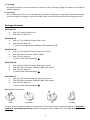
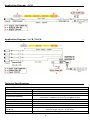
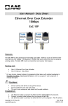
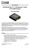
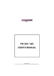
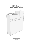
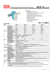
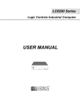
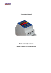
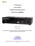
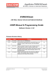
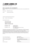
VPoC User Manual Video & Power Over Coax VPoC Step Down 12V DC Receiver - Camera Side VPoC2412DC Red Logo N-41C 1CH Video Power over Coax VPoC24DC-01 Blue Logo N-42-1 4CH / 8CH / 16CH Video Power over Coax Server VPoC24DC-04 VPoC24DC-08-120 VPoC24DC-08-220 VPoC24DC-16-120 VPoC24DC-16-220 4 CH 120V~220V AC 8CH 120V AC 8CH 220V AC N-43-4 16CH 120V AC 16CH 220V AC N-44-8 N-45-16 Features .. Can run Coax Cable up to 300m / 1000ft without power drop Easy to upgrade to PTZ camera with existing 18/2 power wire to become data RS485 No need to lay AC line and install power adapter to camera 1 cable for power and video transmission, reducing the material cost Enhanced anti-interference capability Copyright © 2012 by AAS Technology www.AAS.com.tw N-41C / N-42-1 / N-43-4 / N-44-8-120 N-44-8-220 / N-45-16-120 / N-45-16-220 R201204-V20 Please read the Manual before attempting to use this product. Specifications and appearance are subject to change without notice. Disposal of Old Electrical & Electronic Equipment (Applicable in the European Union and other European countries with separate collection systems). This symbol on the product or on its packaging indicates that this product shall not be treated as household waste. Instead it shall be handed over to the applicable collection point for the recycling of electrical and electronic equipment. By ensuring this product is disposed of correctly, you will help prevent potential negative consequences for the environment and human health, which could otherwise be caused by inappropriate waste handling of this product. The recycling of materials will help to conserve natural resources. For more detailed information about recycling of this product, please contact your local city office, your household waste disposal service or the shop where you purchased the product. Caution .. 1. Handle this product with care Avoid any shock or bumping of the product. Improper handling could damage the product. Do not handle the unit with wet hands. Provide proper ventilation and air circulation and do not use near water. Do not handle the product with wet hands. 2. Requires a proper operating environment This product is not waterproof and is designed for indoor use. The allowable temperature range for operation of this product is between -20C~50C. 3. Check the power source voltage The power source voltage should be within the specified range. (Product must meet the specifications). 4. Objects and liquid entry Never push objects of any kind into this product as this may touch dangerous voltage points of short out parts that could result in a fire or electric shock. Never spill any kind of liquid on the product. 2 5. Cleaning Do not use liquid or aerosol cleaners to clean this unit. Always unplug the power to the device before cleaning. 6. Servicing Do not attempt to service this product by yourself as opening or removing covers may expose you to dangerous voltage or other hazards. Refer all service to qualified servicing personnel. Package Contents .. VPoC2412DC One (1) Camera Side device One (1) User Manual VPoC24DC-01 One (1) 1 CH Video & Power Over Coax One (1) User Manual * 24V DC 1A Single Power Adapter Sold Separately VPoC24DC-04 One (1) 4 CH Video & Power Over Coax Server One (1) DVR Connector Cable (4 BNC) One (1) User Manual * Power Cord Sold Separately VPoC24DC-08 One (1) 8 CH Video & Power Over Coax Server Two (2) DVR Connector Cables (4 BNC each cable) One (1) User Manual * Power Cord Sold Separately VPoC24DC-16 One (1) 16 CH Video & Power Over Coax Server Two (2) DVR Connector Cables (8 BNC each cable) One (1) User Manual * Power Cord Sold Separately Available Plug Types: USA Australia UK Europe For any returns, please include all components listed above with original packaging in Resalable Condition. Absolutely No Returns will be accepted if any component is missing/damaged. 3 Application Diagram – 1CH .. Application Diagram – 4 / 8 / 16 CH .. Technical Specifications .. Camera Side: Video Output + Power Input Model Input Voltage Output DC Voltage Transmission Distance Transmitting Cable Video Connector Power Connector Video & Power Transmission Dimension LxWxH Weight VPoC2412DC 12V DC 24V DC 300m / 1000ft when working with 1 CH DVR Under 300m / 1000ft when working with 4/8/16 CH DVR Coax 1 Male BNC with Cable, Resistance 75 Ohms 24V DC Jack BNC 64(L) x 28(W) x 21(H) mm / 2.52(L) x 1.10(W) x 0.83(H) inches with lead length 20 mm / 10.24 inches 57 g / 2 oz 4 DVR Side Model Output DC Voltage Output Rated Current ; Range Output Rated Power Ripple & Noise (Note #2) Voltage Adj. Range Voltage Tolerance (Note #3) Line Regulation (Note #4) Load Regulation (Note #5) VPoC24DC-01 1.0A Over Voltage Protection 4.5A ; 22.8 ~ 26.4V 8.8A ; 20 ~ 26.4V 108W 211.2W --- 200mVp-p 120mVp-p 150mVp-p --- 21.6~26.4V 22.8 ~ 26.4V --- + 1.0% --- + 0.5% --- + 0.5% --- Leakage Current Overload Protection 3.2A ; 0~3.2A 76.8W Hold Up Time (Typ.) Inrush Current VPoC24DC-16 --- --- Frequency Range Efficiency (Typ.) Input AC Current VPoC24DC-08 24V DC Setup, Rise Time Input Voltage Range VPoC24DC-04 100~240V AC 500ms, 30ms/230VAC 1200ms, 30ms/115VAC at full load 50ms/230VAC 10ms/115VAC at full load 500ms, 20ms/230VAC 500ms, 20ms/115VAC at full load 30ms/230VAC 25ms/115VAC at full load 85~264V AC 120~370V DC 85~132V AC / 176~264V AC selected by switch 248~373V DC 50~60 Hz 1000ms, 50ms/230VAC 1000ms,50ms/115VAC at full load 20ms/230VAC 16ms/115VAC at full load 90~132V AC / 180~264V AC selected by switch 254~370V DC 47~63 Hz --- 86% 87% 0.8A 1.5A / 115V AC 0.9A / 230V AC 2A / 115V AC 1.2A / 230V AC 4.5A / 115V AC 2.5A / 230V AC --- COLD START 45A COLD START 36A 40A/115VAC 55A/230VAC --- <2mA / 240VAC <3.5mA / 240VAC --- 110~150% rated output power 105~150% rated output power --- 27.6~32.4V Hiccup mode, recovers automatically after fault condition is removed Working Temp. Working Humidity Storage Temp. ; Humidity Temp. Coefficient --- Vibration --- 10 ~ 500Hz, 2G 10min./1cycle, period for 60min. each along X, Y, Z axes Safety --- UL60950-1, CB(IEC60950-1),CCC GB4943 -20°C ~ +60°C (Refer to "Derating Curve") ------- -20°C ~ +50°C 20 ~ 90% RH non-condensing -40°C ~ +85°C ; 10 ~ 95% RH + 0.03% / °C (0°C ~ 45°C) 5 -20°C ~ +85°C , 10 ~ 95% RH + 0.03% / °C (0°C ~ 50°C) 10 ~ 500Hz, 3G 10min./1cycle, 60min. each along X, Y, Z axes UL60950-1 approved approved Standards Withstand Voltage Isolation Resistance EMC Emission (Note #6) --- I/P-O/P:3KVAC --- I/P-FG:1.5KVAC I/P-O/P, I/P-FG, O/P-FG:100M Ohms / 500VDC / 25°C / 70% RH Compliance to EN55022 (CISPR22) Class B, EN61000-3-2,-3 Compliance to EN61000-4-2,3,4,5,6,8,11, EN55024, EN61000-6-1, light industry level, criteria A --- EMC Immunity (Note #6) --- EMI Conduction & Radiation --- --- EMS Immunity --- --- MTBF --- Dimension LxWxH Weight O/P-FG:0.5KVAC 64x28x21 mm / 2.52x1.10x0.83 in with lead length 20 mm / 10.24 in 57 g / 2 oz ----Design refer to EN55022 (CISPR22) Class A Design refer to EN61000-4-2, 3, 4, 5, 6, 8,11, ENV50204, EN55024, light industry level, criteria A 378.2K hrs min. MIL-HDBK-217F (25°C) 320.7Khrs min. MIL-HDBK-217F (25°C) 271.9K hrs min. MIL-HDBK-217F (25°C) 248x235x50 mm / 9.76x9.25x1.97 in 248x235x50 mm / 9.76x9.25x1.97 in 342.5x258x65 mm / 13.48x10.16x2.56 in 1.35 kg / 2.98 lbs 1.5 kg / 3.3 lbs 2.3 kg / 5.07 lbs CB Switching Power Certifications CB *Specifications are subject to change without notice Single Power Adapter sold separately Switching Power Supply – Power cord sold separately SPECIFICATION NOTES: 1. 2. 3. 4. 5. 6. All parameters NOT specially mentioned are measured at 230VAC input, rated load and 25 of ambient temperature. Ripple & noise are measured at 20MHz of bandwidth by using a 12" twisted pair-wire terminated with a 0.1uf & 47uf parallel capacitor. Tolerance: includes set up tolerance, line regulation and load regulation. Line regulation is measured from low line to high line at rated load. Load regulation is measured from 0% to 100% rated load. The power supply is considered a component which will be installed into a final equipment. The final equipment must be re-confirmed that it still meets EMC directives. For guidance on how to perform these EMC tests, please refer to “EMI testing of component power supplies” (as available on http://www.meanwell.com) 6 Limited Warranty .. LIMITED ONE (1) YEAR WARRANTY AND EXCLUSIONS Manufacturer warrants to the original consumer purchaser and not for the benefit of anyone else that this product at the time of its sale by Manufacturer is free of defects in materials and workmanship under normal and proper use for one (1) year from the purchase date. Manufacturer's only obligation is to correct such defects by repair or replacement, at its option, if within such one (1) year period the product is returned prepaid, with proof of purchase date, and a description of the problem. This warrant excludes and there is disclaimed liability for labor for removal of this product or reinstallation. This warranty is voided if this product is installed improperly or in an improper environment, overloaded, misused, opened, abused, or altered in any manner, or is not used under normal operating conditions or not in accordance with any labels or instructions. There are no other implied warranties of any kind, including merchantability and fitness or a particular purpose, but if any implied warranty is required by the applicable jurisdiction, the duration of any such implied warrant, including merchantability and fitness of or a particular purpose, is limited to one (1) year. Manufacturer is not liable for incidental, indirect, special, or consequential damages, including without limitation, damage to, or loss of use of, any equipment, loss sales or profits or delay or failure to perform this warranty obligation. The remedies, provided therein are the exclusive remedies under this warranty, whether based on contract, tort or otherwise. 7 MADE IN CHINA Copyright © 2012 by AAS Technology www.AAS.com.tw 8 N-41C / N-42-1 / N-43-4 / N-44-8-120 N-44-8-220 / N-45-16-120 / N-45-16-220 R201204-V20