1
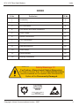
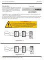
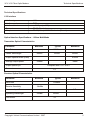
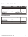
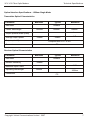
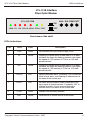
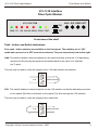
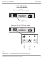
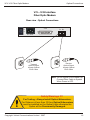
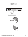
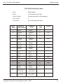
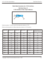
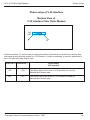
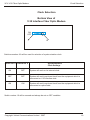
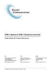
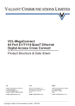
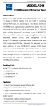
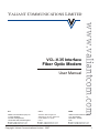
VALIANT COMMUNICATIONS LIMITED
VCL-V.35 Interface
Fiber Optic Modem
User Manual
U.K.
U.S.A.
INDIA
Valiant Communications (UK) Ltd
1, Acton Hill Mews,
310-328 Uxbridge Road,
London W3 9QN, United Kingdom
Valcomm Technologies Inc.
4000 Ponce de Leon, Suite 470
Coral Gables, FL 33146
U.S.A.
Valiant Communications Limited
71/1, Shivaji Marg,
New Delhi - 110015,
India
Copyright: Valiant Communications Limited - 2007
1
Notice
VCL-V.35 Fiber Optic Modem
Warranty
This Valiant product is warranted against defects in material and workmanship for a period of one
year from the date of shipment. During the warranty period, Valiant will, at its discretion, either repair
or replace products which prove to be defective. For warranty service or repair, this product must be
returned to a service facility designated by Valiant. The buyer shall prepay shipping charges to
Valiant and the company shall pay shipping charges to return the product to the buyer. However, the
buyer shall pay all the shipping charges, duties and taxes for products returned to Valiant from
another country.
Limitation of Warranty
The foregoing warranty shall not apply to defects resulting from improper or inadequate
maintenance by the buyer, buyer-supplied firmware or interfacing, unauthorized modification or
misuse, operation outside of the environmental specifications for the product or improper site
preparation or maintenance.
Exclusive Remedies
The remedies provided herein are the buyer’s sole and exclusive remedies. Valiant shall not be
liable for any direct, indirect, special, incidental or consequent damages, whether based on contract
or any legal theory.
Notice
This manual contains information that is proprietary to Valiant Communications Limited. No part of
this publication may be reproduced in any form whatsoever without prior written approval by Valiant
Communications Limited
Safety Warnings
!
The exclamation point within a triangle is intended to warn the operator or service
personnel of operation and maintenance factors relating to the product and its
operating environment which could pose a safety hazard.
Always observe standard safety precautions during installation, operation and maintenance of this
product. Only a qualified and authorized service personnel should carry out adjustment,
maintenance or repairs to this instrument. No adjustment, maintenance or repairs should be
performed by either the operator or the user.
UALITY ASSURANCE PROGRAM
Valiant’s products are designed and manufactured under a strict Quality
Assurance Program based on the ISO 9000 philosophy and principles.
Valiant pays very special attention to its vendor development program
which ensures an “end-product” of the highest quality at the most cost
effective prices.
Copyright: Valiant Communications Limited - 2007
2
Index
VCL-V.35 Fiber Optic Modem
INDEX
Particulars
S. No.
P. No.
1.
Introduction
4
2.
Technical Specifications
5
3.
LED Indications
8
4.
Push Button and Switch indications
9
5.
Power Supply
11
6.
Optical Connections
12
7.
V.35 Connections
13
8.
Cabling details
14
9.
Data rate selection
16
10.
Phase Setup
18
11.
Clock Selection
19
12.
Ordering Information
20
Safety Warnings !!!!
For Testing : Always Install Optical Attenuators.
For Distance of less than 10 Kms Optical Attenuators
must be installed on the Optical Links otherwise the
Optics will be Permanently Damaged.
CAUTION
ELECTROSTATIC
SENSITIVE
DEVICES
DO NOT OPEN OR HANDLE
EXCEPT AT A
STATIC-FREE WORKSTATION
Copyright: Valiant Communications Limited - 2007
3
Introduction
VCL-V.35 Fiber Optic Modem
Introduction
Front view
The VCL-V.35 Fiber Optic Modem provides the
user the capability to establish communication
between two V.35 interfaces or between an
E1/FE1 interface and a “n”x64 V.35 interface
over an optical fiber link.
VCL-V35-FOM
VCL-V.35 Interface
Fiber Optic Modem
It establishes a secure, long range data fiber link between computers, routers, multiplexers and
other V.35 or E1 data communication devices.
The primary application for the VCL-V.35 Fiber Optic Modem is to establish point-to-point fiber link
at ranges longer than any copper modem can achieve. The clock options are Internal/External/
Slave Clock - three clock mode option.
Safety Warnings !!!!
V.35
Optical
Fiber
VCL- V.35 Fiber
Optic Modem
Network
VCL- V.35 Fiber
Optic Modem
For Testing : Always Install Optical Attenuators.
For Distance of less than 10 Kms Optical Attenuators
must be installed on the Optical Links otherwise the
Optics will be Permanently Damaged.
V.35
ROUTER
FE1
Optical
Fiber
VCL- V.35 Fiber
Optic Modem
Network
VCL- V.35 Fiber
Optic Modem
Application -1
V.35
ROUTER
Application -2
Copyright: Valiant Communications Limited - 2007
4
Technical Specifications
VCL-V.35 Fiber Optic Modem
Technical Specifications
V.35 Interface
Interface type
Interface mode
Interface bit rate
Connector
Adapter
V.35
DCE
nx64 Kbps (n=1-32)
DB-25 (Female)
DB-25 (Male) to M34 Winchester (Female)
Optical Interface Specifications - 850nm Multi Mode
Transmitter Optical Characteristics
Parameter
Minimum
Data Rate
Center Wavelength
Typical
125Mb/s
830nm
850nm
Output Spectral Width (RMS)
Average Output power
Maximum
860nm
0.85nm
-10dBm
Output optical Eye
-3dBm
Complaint with ITU-T G.957
Connectors
FC
Receiver Optical Characteristics
Parameter
Minimum
Data Rate
Receive Sensitivity
Typical
125Mb/s
-24dBm
-3dBm
Maximum Input Power
Operating Wavelength
Maximum
-10dBm
Connectors
Copyright: Valiant Communications Limited - 2007
850nm
FC
5
Technical Specifications
VCL-V.35 Fiber Optic Modem
Optical Interface Specifications - 1310nm Single Mode
Transmitter Optical Characteristics
Parameter
Minimum
Data Rate
Center Wavelength
Typical
125Mb/s
1260nm
1310nm
1360nm
6nm
Output Spectral Width (RMS)
Average Output power
Maximum
-15dBm
Output optical Eye
-12dBm
-8dBm
Complaint with ITU-T G.957
Connectors
FC
Receiver Optical Characteristics
Parameter
Minimum
Data Rate
Receive Sensitivity
Typical
125Mb/s
-32dBm
-15dBm
Maximum Input Power
Operating Wavelength
Maximum
1100nm
Connectors
Copyright: Valiant Communications Limited - 2007
1600nm
FC
6
Technical Specifications
VCL-V.35 Fiber Optic Modem
Optical Interface Specifications - 1550nm Single Mode
Transmitter Optical Characteristics
Parameter
Minimum
Data Rate
Center Wavelength
Typical
125Mb/s
1480nm
1550nm
1580nm
4nm
Output Spectral Width (RMS)
Average Output power
Maximum
-15dBm
Output optical Eye
-12dBm
-8dBm
Complaint with ITU-T G.957
Connectors
FC
Receiver Optical Characteristics
Parameter
Minimum
Data Rate
Receive Sensitivity
Typical
125Mb/s
-32dBm
-15dBm
Maximum Input Power
Operating Wavelength
Maximum
1100nm
Connectors
Copyright: Valiant Communications Limited - 2007
1600nm
FC
7
LEDs Indications
VCL-V.35 Fiber Optic Modem
VCL-V.35 Interface
Fiber Optic Modem
VCL-V35-FOM
ANA DIG REM PATT
ON
PWR TD
RD OPLOS OPSYL PTOK TEST
OFF
Front view of the shelf
LEDs Indications
S. No.
LEDs
Color
Description
1.
PWR
Green
ON indicates that input power supply is OK.
2.
TD
Yellow
Flashing to indicate there is data input in V.35 data
interface; the faster the flashing speed is, the higher
the speed of V.35 interface is. This is a V.35 data
speed indicator.
3.
RD
Yellow
Flashing to indicate there is data input in V.35 data
interface; the faster the flashing speed is, the higher
the speed of V.35 Interface is. This is a V.35 data
speed indicator.
4.
OPLOS
Red
Optical link break alarm; Constantly “ON” to indicate
there is local alarm, and flashing to indicate there is
an alarm at the remote end.
5.
OPSYL
Red
No frame synchronization code is detected in the
input signal of optical interface. Constantly “ON” to
Indicate an alarm of local end and flashing to
indicate there is an alarm at the remote end.
6.
PTOK
Green
Pseudo code normally detected.
7.
TEST
Yellow
Local device or remote device in test mode.
Copyright: Valiant Communications Limited - 2007
8
Push Button and Switch
VCL-V.35 Fiber Optic Modem
VCL-V.35 Interface
Fiber Optic Modem
VCL-V35-FOM
ANA DIG REM PATT
ON
PWR TD
RD OPLOS OPSYL PTOK TEST
OFF
Front view of the shelf
Push - button and Switch Indications
Four push - button switches are available on the front panel. The switches are in “ON”
mode when pressed or in OFF mode when released. They are respectively from left to right.
ANA: This switch initiates a internal loopback on the optical interface so that the V.35 data being
received (on Rx pins) by the system is transmitted back on the same V.35 interface
(on Tx pins).
V.35
VCL- V.35 Fiber
Optic Modem
This test may be used to verify the integrity of the V.35 data interface connections.
Optical Interface
DIG: This switch initiates a internal loopback on the V.35 interface so that the data being received
on the optical (Rx) fiber is sent back on the optical (Tx) fiber through the V.35 interface.
V.35
VCL- V.35 Fiber
Optic Modem
This test may be used to verify the integrity of the optical link.
Optical Interface
Copyright: Valiant Communications Limited - 2007
9
Push Button and Switch
VCL-V.35 Fiber Optic Modem
REM: This switch initiates a loopback at the remote side. It may be used to verify the complete
Fiber
Local End
VCL- V.35 Fiber
Optic Modem
V.35
VCL- V.35 Fiber
Optic Modem
data link integrity between the local and the remote V.35 interface.
V.35
Remote End
PATT: This switch initiates a data link integrity test by generating a pseudo random pattern.
Important:
1. All switches must be in OFF condition during normal operations. Whenever a test switch is used
to initiate a test, the normal communications shall be disrupted.
2. When PATT switch is used to do a data link integrity test please ensure that the far end in a
loopback mode to complete the test circuit.
Copyright: Valiant Communications Limited - 2007
10
Power Supply
VCL-V.35 Fiber Optic Modem
VCL- V.35 Interface
Fiber Optic Modem
Rear view with AC Power supply
V.35
OFF
Tx Rx
ON
AC 220V
Connect AC Input
here
Rear view with -48 V DC Power supply
-E
OFF
-
+
+
+
+
V.35
Tx Rx
ON
DC 48V
-E
-
+
+
+
+
- 48V
- 48 VGND
SGND
Note:
Please connect - 48V DC supply to the system as shown in above figure.
Copyright: Valiant Communications Limited - 2007
11
Optical Connections
VCL-V.35 Fiber Optic Modem
VCL- V.35 Interface
Fiber Optic Modem
Rear view - Optical Connections
V.35
OFF
Tx Rx
ON
AC 220V
Receive
Optical Signal
through Optical
Fiber Cable
Transmit
Optical Signal
through Optical
Fiber Cable
Note: Do not expose to the naked eye.
Connect Fiber Cable to System
When Power is OFF.
Safety Warnings !!!!
For Testing : Always Install Optical Attenuators.
For Distance of less than 10 Kms Optical Attenuators
must be installed on the Optical Links otherwise the
Optics will be Permanently Damaged.
Copyright: Valiant Communications Limited - 2007
12
V.35 Connections
VCL-V.35 Fiber Optic Modem
VCL- V.35 Interface
Fiber Optic Modem
Rear view - V.35 Connections
V.35
OFF
Tx Rx
ON
AC 220V
DB-25 (Female)
Connector
DB-25 (Male)
Connector
V.35 Winchester (Female) connector
Copyright: Valiant Communications Limited - 2007
13
Cabling details
VCL-V.35 Fiber Optic Modem
V.35 (DCE) Interface Cable
End 1
DB-25 (Male)
End 2
V.35 connector (Female)
Type of Cable
Twisted pair cable- solid conductor
No. of pairs
9
Connection
As per details given below
DB-25
(Male)
Signal on
DB-25 (Male)
Signal on
V.35
V.35
PIN
Shelter
Shelter
A
14
Transmit
Data +
Transmit
Data +
S
DTE
2
Transmit
data -
Transmitter
data -
P
DTE
12
Transmit
Timing +
Transmit
Timing +
AA
DCE
15
Transmit
Timing -
Transmit
Timing -
Y
DCE
9
Receive
Timing +
Receive
Timing +
X
DCE
17
Receive
Timing -
Receive
Timing -
V
DCE
16
Received
Data +
Received
Data +
T
DCE
3
Received
Data -
Received
Data -
R
DCE
20
DTR
DTR
H
DTE
6
DSR
DSR
E
DCE
4
RTS
RTS
C
DTE
5
CTS
CTS
D
DCE
8
DCD
DCD
F
DCE
7
Signal
Ground
Signal
Ground
B
24
Sending Clk A
(from DTE)
Sending Clk A
(from DTE)
U
11
Sending Clk B
(from DTE
Sending Clk B
(from DTE)
W
1
Copyright: Valiant Communications Limited - 2007
Source
14
Cabling details
VCL-V.35 Fiber Optic Modem
M/34 Winchester-Female
S P
AA Y
XVTR
H E C
FD B
25 pin D-type - pin assignment
view from FRONT side
1
2
3
4
5
6
7
8
9 10 11 12 13
14 15 16 17 18 19 20 21 22 23 24 25
MALE CONNECTOR
DB-25 to M.34 Winchester adapter
Note: This cable supplied with the modem.
Copyright: Valiant Communications Limited - 2007
15
Data Rate Selection
VCL-V.35 Fiber Optic Modem
Data Rate Selection for V.35 Interface
Bottom View of
V.35 Interface Fiber Optic Modem
ON
OFF
1 2 3 4 5 6 7 8 9 10
1
10
Switches number 1-5 will be used for the data rate selection of V.35.
Refer the following table for different data rate selection of V.35 interface.
Switch No. 1 Switch No. 2 Switch No. 3
Switch No. 4
Switch No. 5
Data Rate of V.35
Interface (Kbit/s)
OFF
OFF
OFF
OFF
OFF
64
ON
OFF
OFF
OFF
OFF
128
OFF
ON
OFF
OFF
OFF
192
ON
ON
OFF
OFF
OFF
256
OFF
OFF
ON
OFF
OFF
320
ON
OFF
ON
OFF
OFF
384
OFF
ON
ON
OFF
OFF
448
ON
ON
ON
OFF
OFF
512
OFF
OFF
OFF
ON
OFF
576
ON
OFF
OFF
ON
OFF
640
OFF
ON
OFF
ON
OFF
704
Copyright: Valiant Communications Limited - 2007
16
Data Rate Selection
VCL-V.35 Fiber Optic Modem
Switch No. 1 Switch No. 2 Switch No. 3
Switch No. 4
Switch No. 5
Data Rate of V.35
Interface (Kbit/s)
ON
ON
OFF
ON
OFF
768
OFF
OFF
ON
ON
OFF
832
ON
OFF
ON
ON
OFF
896
OFF
ON
ON
ON
OFF
960
ON
ON
ON
ON
OFF
1024
OFF
OFF
OFF
OFF
ON
1088
ON
OFF
OFF
OFF
ON
1152
OFF
ON
OFF
OFF
ON
1216
ON
ON
OFF
OFF
ON
1280
OFF
OFF
ON
OFF
ON
1344
ON
OFF
ON
OFF
ON
1408
OFF
ON
ON
OFF
ON
1472
ON
ON
ON
OFF
ON
1536
OFF
OFF
OFF
ON
ON
1600
ON
OFF
OFF
ON
ON
1664
OFF
ON
OFF
ON
ON
1728
ON
ON
OFF
ON
ON
1792
OFF
OFF
ON
ON
ON
1856
ON
OFF
ON
ON
ON
1920
OFF
ON
ON
ON
ON
1984
ON
ON
ON
ON
ON
2048
Copyright: Valiant Communications Limited - 2007
17
Phase setup
VCL-V.35 Fiber Optic Modem
Phase setup of V.35 Interface
Bottom View of
V.35 Interface Fiber Optic Modem
ON
OFF
1 2 3 4 5 6 7 8 9 10
1
10
Switches number 6-7 will be used for setting the phase relationship of transmit and receive data
and sending and receiving clocks for V.35 interface. It may be necessary to use this adjustment if
the V.35 communication fails to start.
Switch No. 6 Switch No. 7
Phase setup
V.35 Interface
ON
ON
The falling edge of the clock of V.35 Interface is used for
transmit and receive data.
OFF
OFF
The rising edge of the clock of V.35 Interface is used for
transmit and receive data.
Copyright: Valiant Communications Limited - 2007
18
Clock Selection
VCL-V.35 Fiber Optic Modem
Clock Selection
Bottom View of
V.35 Interface Fiber Optic Modem
ON
OFF
1 2 3 4 5 6 7 8 9 10
1
10
Switches number 8-9 will be used for selection of synchronization clock.
Switch No. 8 Switch No. 9
Synchronization
Clock Settings
ON
OFF
System will work on its internal clock.
OFF
OFF
System will work loop-timed clock from the equipment which is
connected on V.35 interface side.
ON
ON
System will work loop-timed clock from the equipment which is
connected on optical side.
Switch number 10 will be unused and always be set on OFF condition.
Copyright: Valiant Communications Limited - 2007
19
Ordering Information
VCL-V.35 Fiber Optic Modem
Ordering Information
Sr. No.
Product Description
Part No.
1.
VCL-V.35 Fiber Optic Modem - 850 nm
wavelength with AC power supply
VCL-V35 FOM-850-AC
2.
VCL-V.35 Fiber Optic Modem - 850 nm
wavelength with DC power supply
VCL-V35 FOM-850-DC
3.
VCL-V.35 Fiber Optic Modem - 1310 nm
wavelength with AC power supply
VCL-V35 FOM-1310-AC
4.
VCL-V.35 Fiber Optic Modem - 1310 nm
wavelength with DC power supply
VCL-V35 FOM-1310-DC
5.
VCL-V.35 Fiber Optic Modem - 1550nm
wavelength with AC power supply
VCL-V35 FOM-1550-AC
6.
VCL-V.35 Fiber Optic Modem - 1550 nm
wavelength with DC power supply
VCL-V35 FOM-1550-DC
Technical specifications are subject to changes without notice.
Revision 03 - October 20, 2007.
U.K.
U.S.A.
INDIA
Valiant Communications (UK) Ltd
1, Acton Hill Mews,
310-328 Uxbridge Road,
London W3 9QN, United Kingdom
Valcomm Technologies Inc.
4000 Ponce de Leon, Suite 470
Coral Gables, FL 33146
U.S.A.
Valiant Communications Limited
71/1, Shivaji Marg,
New Delhi - 110015,
India
Copyright: Valiant Communications Limited - 2007
20