1
University of Stuttgart
Institute of Industrial Automation and Software Engineering
Prof. Dr.-Ing. M. Weyrich
Laboratory Course Industrial Automation
Experiment No. 5
Rapid Prototyping with ASCET-SD
Experiment Instructions
Room 1.126
2
Rapid Prototyping with ASCET-SD
Table of Contents
1 Introduction ..........................................................................................................................3
1.1 Development of Automation Software ...........................................................................3
1.2 Rapid Prototyping ...........................................................................................................3
1.3 Content and Goal of the Experiment ..............................................................................4
2 Computer-based Software Development with ASCET-SD ..............................................5
2.1 The Software Development Tool ASCET-SD ...............................................................5
2.2 Modeling with ASCET-SD.............................................................................................6
2.3 Modules and Classes.......................................................................................................7
2.4 Code Generation and Hardware Configuration ..............................................................9
2.5 Simulation and Rapid-Prototyping ...............................................................................10
2.6 Short User Manual for ASCET-SD ..............................................................................11
3 The Experiment ..................................................................................................................13
3.1 Objective .......................................................................................................................13
3.2 Conducting the Experiment ..........................................................................................15
3.3 The module PitmanArmDecoder ..................................................................................16
3.4 The module WiperControl ............................................................................................16
3.5 The module WiperDiagnosis ........................................................................................17
4 Literature ............................................................................................................................18
5 Appendix .............................................................................................................................19
5.1 Hardware architecture of the experimental system.......................................................19
5.2 ASCET-SD Descriptive Elements ................................................................................22
5.3 Operators (C or Java syntax) ........................................................................................25
5.4 Subset of the ASCET-SD system library......................................................................26
Rapid Prototyping with ASCET-SD
3
1 Introduction
1.1 Development of Automation Software
The increase of electronics in modern technical systems has become one of the main challenges
in software development. In the automotive sector, for example, more and more functions are
realized by electronic control units (ECUs) in order to improve operability, comfort, ecofriendliness and safety. Mass products like photo cameras, washing machines, or telephones all
have built-in micro-controllers which execute control and supervisory functions. A considerable
part of the system functionality is thereby realized by the software running on a micro-controller
or an ECU.
In order to cope with the growing complexity of the software, software development processes
more and more demand computer-based development tools (e.g. modeling, simulation or code
generation tools). A software development process describes not only the tools but also the work
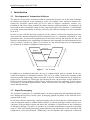
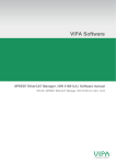
sequence and methods to be used during development. One frequently used development process
is the so-called V-model (see Figure 1). It consists of a top down design process complemented
by a bottom up realization, integration, and test process.
t
Definition &
Analysis
Referencing
Test
t
Design
Implementation
Figure 1: The V-model
In addition to a methodical procedure, the use of computer-based tools is essential for the successful development of automation systems. The use of so called CASE tools (computer aided
software/systems engineering) makes it possible to specify control functions not in natural language but in a formal way. During the specification process, the developer creates models in a
formal or semi-formal language, which can be further processed by computers. In this context,
one speaks of "executable specifications" which can be used for an early validation of requirements and functionality.
1.2 Rapid Prototyping
The creation of prototypes is a standard practice in many engineering and manufacturing industries. During the last ten or twenty years, prototyping gained acceptance in the software development field, as well.
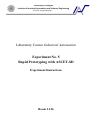
In real-time software engineering, rapid prototyping refers to the production of demonstrators in
early development stages to validate initial concepts. A software prototype realizes only the relevant parts of the presumed system and allows the validation of requirements or the comparison
of alternative designs. The task is to produce an executable demonstrator as quickly as possible
using a CASE tool. Rapid prototyping permits therefore fast conclusions on the correctness and
completeness of the specifications. Additionally, the development and comparison of different
4
Rapid Prototyping with ASCET-SD
alternatives is simplified, which enables a fast iterative development Figure 2 shows the principle structure of rapid prototyping hardware to execute the software.
Figure 2: Principle structure of rapid prototyping hardware
1.3 Content and Goal of the Experiment
The goal of this laboratory experiment is to provide an in-depth look into modern software development for automation systems using computer-based development tools. In this experiment,
the control software for an automotive windscreen wiper control system is designed, simulated
and realized using the CASE-Tool ASCET-SD1 from the ETAS company.. he system consists of
a computer node, wipers and a pitman arm.
In order to complete this experiment successfully, a thorough preparation is mandatory.
Complete the preparatory tasks in Chapter 3 in written form before the beginning of the
experiment. Record the results you obtain during the experiment.
1
ASCET-SD = Advanced Simulation Control Engineering Tool – Software Development
Rapid Prototyping with ASCET-SD
5
2 Computer-based Software Development with ASCET-SD
2.1 The Software Development Tool ASCET-SD
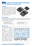
ASCET-SD is a CASE used in the automotive sector to develop complex real-time embedded
control software. The product from the ETAS company supports the complete software development process by using a uniform work environment. It integrates different tool components
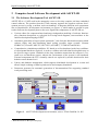
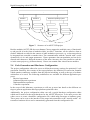
into a comprehensive development environment (see Figure 3), which makes it possible to pass
results from one development phase to the next. Significant components of ASCET-SD are:
Various editors for component-based and target independent modeling of software functionality (function description) at a physical level using block diagrams, state machines or the
function description language ESDL2.
Automatic generation of target system optimized C code from the function description which
replaces faulty and time-consuming hand coding (possible target systems: Siemens
SAB80C167, PowerPC MPC555, NECV853 (ATOMIC), TI TMS 470 and 68386).
Comprehensive simulation possibilities: PC-based as well as hardware-in-the-loop (additional experimental hardware required), in order to validate each individual development step on
the specific target system. Hardware-in-the-loop simulation means that the software is executed on a real hardware system, whereas the environment of the system is still simulated.
External components the ECU normally controls are replaced by models that describe their
behavior on an abstract level.
Library and database management, which supports distributed development in a team and
allows simple exchange of data beyond section and company boundaries.
Document generator for automatic generation of documentation files supporting standard
word processing tools.
Functionality
ASCET-SD
Block diagram
editor
Database
•
ASCET-SD
system
library
• Models
• Data
• Experimental
environment
State machine
editor
ESDL code
editor
If (!l1 &&!l2){
y=u1;}
else if (l1 && !l2){
y=u2;}
C code
editor
If (!l1 &&!l2){
y=u1;}
else if (l1 && !l2){
y=u2;}
Operating system
specification
Documentation,
records
Automatic
documentation
Simulation
environment
ASCET-SD Development Environment
Target systemspecific software
Automatic code generator
Experimental
Target
Simulation on a PC
ECU
Target
Figure 3: ASCET-SD development environment; source: ETAS GmbH & Co. KG
2
Embedded Software Description Language
6
Rapid Prototyping with ASCET-SD
2.2 Modeling with ASCET-SD
To specify software functionality, ASCET-SD offers different description means:
Block diagrams: Block diagrams are used to describe control algorithms (see Figure 4).
Block diagrams represent data flows as well as control flows between functional blocks
graphically. Complex algorithms can be split up into several hierarchies where a functional
block at top level may contain other blocks and so on.
There are three ways of connecting functional blocks:
-
numeric data flow (solid line)
binary data flow (dotted line)
control flow (black-white line)
numeric data flow
functional block
input parameters
sequence call
control flow
binary data flow
return value
Figure 4: ASCET-SD block diagram
Unlike closed-loop control block diagrams, the block diagrams in ASCET-SD are not executed concurrent but time-discrete and sequential. By using a control flow notation and socalled sequence calls, the execution order is fixed and coupled to a process or a method. Figure 4 for example shows a block diagram equivalent to the following C function.
bool compare(int arg) {
static int buffer = 0;
bool flag;
1
if (comp = = buffer) {
flag = true;
} else {
flag = false;
}
2
buffer = comp;
3
return flag;
}
/* Variable retains its value when leaving */
/* Auxiliary variable */
Rapid Prototyping with ASCET-SD
7
State machines: Complex circuit applications can be described in a more suitable way with
state machines. ASCET-SD’s state machine editor can be used to define graphical states and
transitions (see Figure 5). The conditions and actions that happen upon transition between
states or upon entering, waiting in or leaving a state can be formulated either by graphical
block charts or as ESDL code (Java or C syntax). Unambiguousness and parallelism are
achieved by attributing the transitions, i.e. by assigning priorities to the transitions. The transitions are checked according to the sequence of their priorities and eventually executed.
(transition) condition
start state
priority (prio 1 < prio 2)
transition
state
Figure 5: ASCET-SD state machine
In addition to the described graphic modeling concepts, ASCET-SD also offers two textual meas
of description:
ESDL: Not all algorithms in modern real-time systems are purely control algorithms. Other
algorithms e.g., for diagnostics or fault memory management can often be better formulated
in a text-based manner. In order to describe algorithms of such types in a suitable manner,
ASCET-SD offers with ESDL a target-independent text-based language based on Java syntax.
C-Code: Certain parts of control software cannot be abstracted to a physical level (e.g. hardware encapsulation). To describe these parts, an editor is available which allows the usage of
C code. Based on the C code editor, existing sources can be easily integrated either as source
or object files. Furthermore, complete C libraries can easily be included and utilized.
2.3 Modules and Classes
On the top-level, an ASCET-SD model is composed of so called modules, which communicate
with each other using asynchronous state messages. For example, the model depicted in Figure 6
is composed of two modules which communicate using three messages. The assignment of output messages to input messages is realized by their names.
8
Rapid Prototyping with ASCET-SD
module
process
assignment (via name)
output message
input message
Figure 6: ASCET-SD modules
To specify the behavior of a module you can use the means of description described in the previous chapter. For example, the left module may be specified using a block diagram, the right
module may be specified using an embedded state machine3.
Modules only possess (an unlimited number of) processes4 but no methods (operations). Processes are called by the real-time operating system. As standard, the real-time operating system
ERCOSEK is used. The scheduling model of ERCOSEK is based on a priority-controlled multitasking, which masters cooperative as well as preemptive multitasking. The operating system
does not call processes individually but rather bundled in sequences, the so-called tasks5. Each
task has its own defined priority (priority 0 is the highest priority). Depending on the setting,
tasks are triggered
cyclically
by hardware or software interrupts
or one-time only by initialization
To bundle modules and tasks and to configure the single tasks (which finally determines the time
behavior of a model) so called projects are used in ASCET-SD (cf. Figure 7).
3
Note: A module cannot be specified directly by a state machine, as state machines can only be realized as classes
(cp. end of the chapter). But a class can be integrated into a module.
4
In ASCET-SD, a “process” describes a kind of parameter-free method which may be part of a computation process. Computation processes themselves are called „tasks“ in ASCET-SD.
5
A task corresponds to a computation process.
Rapid Prototyping with ASCET-SD
9
Project
Module A
Module B
Process A1
Process B1
Process A2
Process B2
Real-time operating system
Task 1
Task 2
Process A1
Process B2
Process B1
Process A2
Figure 7: Structure of an ASCET-SD project
Besides modules ASCET-SD also uses classes. Classes support the multiple reuse of functionality and provide it in the form of methods which, just like C functions, can be called as often as
needed. Methods are called in the context of other methods or processes e.g. a class must always
be integrated into a module or another class. The communication with the “outside wold” occurs
dynamically via in- and output parameters. Classes guarantee data encapsulation and can be instanced more than once. Different instances of the same class may also exist parallel to each other in the same project (e.g. different timers). Classes can contain other classes but no modules.
2.4 Code Generation and Hardware Configuration
The project configuration editor also serves to define the necessary settings for optimized C code
generation. Basically, this consists of the target platform, the definition of conversion formulas
which quantize continuous variables from the physical modeling, as well as the type of software
architecture to be used. The following architectures are available for different application purposes:
-
Physical experiment
Quantized physical experiment
Implementation experiment
Controller experiment
In the scope of this laboratory experiment we will not go more into detail on the different settings to generate application and target platform optimized codes.
Additionally, the project configuration editor can call a special hardware configuration editor
which can be used to set the target hardware for the ASCET-SD project. To be more precise, this
editor serves to create a hardware configuration file, which maps messages to hardware ports.
These ports can be seen as the interface of the target microcontroller to the “outside world”. Afterwards a hardware driver can be automatically generated from this configuration file.
10
Rapid Prototyping with ASCET-SD
2.5 Simulation and Rapid-Prototyping
ASCET-SD offers a so-called offline simulation to check the function of a designed component.
The offline simulation is a PC-based simulation, which uses the same data basis as the code generator. That means, model or the components in the simulation are also used for code generation.
As the simulation of closed-loop controllers is only meaningful together with the technical process it controls, ASCET-SD also supports the modeling and simulation of continuous time systems, e.g. electrical, mechanical or hydraulic components. Continuous time models can be combined with ASCET-SD modules to form hybrid models. The name hybrid model refers to the
fact that the model consists of both, time-continuous and time-discrete components.
A continuous time model is built up of basic blocks. They are specified using the differential
equations of the technical process as known from mathematics . Continuous time models are
only used for simulation and not to generate C code. In order to create and simulate a hybrid
model, modules and continuous time blocks have to be coupled graphically (and not via names)
in the context of a project. The differential equations of the continuous time model are solved
during the simulation by real-time integration procedures. The configuration of the solution procedures can be interactively changed during the simulation.
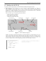
The simulation runs in a comfortable interactive experimental environment (see Figure 8). There
are display and calibration elements to visualize or manually manipulate variable and parameter
values (oscilloscopes, line printers, bar charts, etc.). Yet, these elements are not part of the investigated model but rather can be interactively stored and configured in the experimental environment independent from the model itself. Data can be recorded in real-time and written in a file
for later analysis. It can be also inserted in the form of signals into the simulation.
Stop
Start
Calibration element
Pause
Display element
Figure 8: Experimental environment for simulations
Since the offline simulation is a PC-based simulation, the program execution normally controlled
by the real-time operating system must be simulated, as well. For this purpose, the so-called
Event Generator creates events that trigger processes or tasks in the simulation. Trigger modes
and priorities for the processes and tasks in the simulated project can be set via the menu command Experiment > Event Generator > Open.
During the PC-based simulation, the temporal behavior of the automation computer as well as
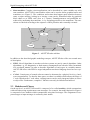
the controlled technical process is emulated. For a more realistic simulation, ASCET-SD offers
the so-called online simulation. This simulation is executed in real-time and sensors, actuators
as well as the real technical process can be included in the simulation (see Figure 9). The simulation does not run on the PC, but rather on an experimental platform under the control of the real-
Rapid Prototyping with ASCET-SD
11
time operating system ERCOSEK. In this laboratory experiment, the experimental platform
ES1000 of the company ETAS will be used. Plug-in cards serve as an intelligent IO system.
Experimental
platform
Intelligent
IO system
Technical
process
Development PC
Figure 9: Experimental system for online simulations
2.6 Short User Manual for ASCET-SD
After starting ASCET-SD and pressing the button in the middle of the small startup window, the
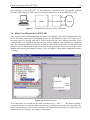
user is forwarded to the ASCET-SD database browser. The database browser (see Figure 10) is
the main panel for working with ASCET-SD. On the left side, all existing components of the
current database are displayed, whether they are classes, modules, state machines or something
else. The hierarchical directory structure is similar to the Windows Explorer. On the right-hand
side you will see information on the currently selected component. If you are not in the correct
database after starting the database browser, you can change it via the menu command Database
> Change.
Figure 10: Database browser
New components are created via the menu command Item > Add... > ... By double-clicking a
component an editor is opened. When components are being processed the user principally uses
the left mouse button to select or move elements, the right mouse button opens a context menu or
switches between “moving” and “linking” components.
12
Rapid Prototyping with ASCET-SD
The simulations are started via the context menu commands, using the right mouse button, experiment > offline and experiment > online. Offline experiment is the term for a PC-based simulation of any component; online experiment is the hardware-in-the-loop simulation of a project.
For online experiments, the target platform and the corresponding compiler must be chosen in
the project configuration editor. For the ES1000 the Diab compiler is used. In addition, the
hardware configuration editor must be opened with the menu command Tools > RTIO > Open
Editor, a configuration file must be loaded and with the help of the Build > Generate Code
command a hardware driver must be generated.
Further information about ASCET-SD can be found in the ASCET-SD User’s Guide, ETAS
GmbH & Co. KG.
Rapid Prototyping with ASCET-SD
13
3 The Experiment
3.1 Objective
In this experiment, the control software for an automotive wiper control system consisting of a
computer node, wipers and a pitman arm is to be developed using the CASE-tool ASCET-SD.
The wiper is to be operated using the pitman arm and in case of a fault, i.e. electric overload or
wiper arm blockage, to be stopped. Instead of an ECU, the development and experimental platform ES1000 from the company ETAS will be used as processing unit to enable rapid prototyping. Wiper and pitman arm are typical chassis electronic components. The experimental system
is already assembled and wired, so that the student can concentrate on the software development.
You will find a short description of the individual hardware components in the appendix.
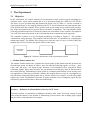
The controller software is to be developed modularily according to Figure 11. The modules
communicate using messages. The module PitmanArmDecoder is responsible for evaluating the
pitman arm signals. The module WiperDiagnostics stops the wiper in case of a fault. Finally the
module WiperControl realizes the actual control of the wiper.
PitmanArmDecoder
DesiredWiperSpeed
WiperDiagnostics
SetWiperSpeed
WiperControl
Figure 11: Software architecture of the experimental system
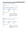
Module PitmanArmDecoder
The module PitmanArmDecoder evaluates the input signals of the pitman arm and generates the
desired wiper speed. As shown in Table 1, there are only the following signals: „no wipe“, „slow
wipe“ and „fast wipe“. An “interval wipe function” is not intended in this experiment. When
evaluating signals, please note that they are not debounced so that they must be debounced by
the control software. Debouncing of input signals is a common problem that occurs in many control applications. When the user pushes a button, this usually does not result in a rectangular signal with sharp rising and falling edges due to electric effects. For example, several rising edges
might occur, while a pushbutton is pressed. In order to obtain a clear rectangular signal, the signal must be preprocessed which is known as debouncing.
debounce – Definition in Maxim/Dallas Glossary of EE Terms
Electrical contacts in mechanical pushbutton switches often make and break contact several
times when the button is first pushed. A debouncing circuit removes the resulting ripple signal,
and provides a clean transition at its output.
14
Rapid Prototyping with ASCET-SD
Input messages
Output messages
Name
SlowWipe
FastWipe
IntervalWipe
DesiredWiperSpeed
Type Code
log6
log
log
udisc7 0 = "no wipe"
1 = "slow wipe"
2 = "fast wipe”
Table 1: Message catalog for module PitmanArmDecoder
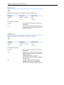
Module WiperDiagnostics
The module WiperDiagnostics should stop the wiper in case of a fault, i.e. if the wiper is blocked
or the power switch is overloaded. The following is valid (cf. Fehler! Verweisquelle konnte
nicht gefunden werden.):
Normal operation:
Fault operation:
SetWiperSpeed := DesiredWiperSpeed
SetWiperSpeed := -1
Faulty operation occurs when the following statement remains true longer than a parameterized
time TError,max :
Error_Overload1 OR Error_Overload2 OR
(Error_PA1 AND WiperSlow) OR (Error_PA2 AND WiperFast)
The faulty case will remain until the fault has been removed and the DesiredWiperSpeed has
been set to zero. This prevents the wiper from automatically moving again after the fault has
been removed.
Input messages
Name
DesiredWiperSpeed
Type
udisc
Output messages
WiperSlow
WiperFast
Error_PA1
Error_PA2
Error_Overload1
Error_Overload2
SetWiperSpeed
log
log
log
log
log
log
disc
Code
0 = "no wipe"
1 = "slow wipe"
2 = "fast wipe”
-1 = "Fault"
0 = "no wipe"
1 = "slow wipe"
2 = "fast wipe”
Table 2: Message catalog for the module WiperDiagnostics
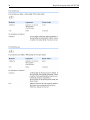
Module WiperControl
First, the WiperControl has to make sure that both control signals WiperSlow and WiperFast are
never simultaneously active. Second, the wiper may only be stopped in its standby position, un-
6
log = logical
7
udisc = unsigned discrete
Rapid Prototyping with ASCET-SD
15
less a fault occurs which should immediately cause the wiper to stop. The standby position is
signaled by the message WiperStandbyPosition.
Input messages
Output messages
Name
SetWiperSpeed
Type
disc8
WiperStandbyPosition
WiperSlow
WiperFast
log
log
log
Code
-1 = "error"
0 = "no wipe"
1 = "slow wipe"
2 = "fast wipe”
Table 3: Message catalog for the module WiperControl
3.2 Conducting the Experiment
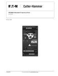
The process model IAS cockpit (see Figure 12) will serve as experimental system. Only part of
its function will be used in this experiment. The experimental system is already assembled and
wired. You will find a short description of the individual hardware components in the appendix.
Figure 12: Model process IAS cockpit
8
disc = discrete
16
Rapid Prototyping with ASCET-SD
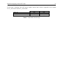
As development system, ASCET-SD Version 3.0 will be used. A database has already been laid
out named LabCourse_IA to start quickly with the experiment. The database includes following
directories
The ETAS_xy directories contain the system library delivered by ETAS.
The components created during the laboratory course are to be stored according to groups in
the “Vorgaben” directories. The directories contain completed components that may be used
by the groups.
The IAS_Fachpraktikum directory contains a specimen solution.
In addition, a hardware configuration file named HWC.hwc already exists.
Complete the preparatory tasks in Chapter 3 in written form before the beginning of the
experiment. Record the results you obtain during the experiment.
Attention! The wiper can cause injury! Never touch the mechanical parts of the wiper during
operation.
3.3 The module PitmanArmDecoder
Preparation task 1: Explain briefly the concepts module, class, project, continuous time block,
process, task, block diagram, state machine and ESDL. Refer to application purpose, differences, as well as dependencies.
Preparation task 2: The module PitmanArmDecoder described in chapter 3.1 shall be modeled
using a block diagram. Design such a block diagram with the help of the elementary function
blocks shown in the appendix. How can the input signals be principally debounced using
software techniques? Consider possible solutions.
Experiment 1: Model the module designed in task 2 with help of the ASCET-SD block diagram
editor. You can use the components provided by the ETAS system library (e.g. timer and
flanks detectors, cf. chapter 5.4). Simulate the module with help of an offline simulation. Define the trigger modes and priorities of the existing processes in the Event Generator. Set the
calibration elements for the input messages and the display elements for the output messages.
Start the simulation and experiment with it.
3.4 The module WiperControl
Preparation task 3: The wiper control described chapter 3.1 shall be modeled using a state machine. Design such a state machine in an arbitrary notation you are familiar with. Take into
account that the wiper may only be stopped in his initial position unless there is a faulty operation. In the fault case it shall, however, be stopped immediately.
Experiment 2: Model the state machine designed in task 3 with help of the ASCET-SD state
machines editor. Then embed the state machine into the module WiperControl. Simulate the
module. Use "animated states" which highlight the current state in color.
Preparation task 4: It is only reasonable to simulate the wiper control together with a model of
the wiper itself. Think of mathematical equations, which could model the wiper sufficiently
exact. Base your considerations on the wiper input signals WiperSlow and WiperFast and the
wiper output signal WiperHomePosition. How can you determine a function that is describing
Rapid Prototyping with ASCET-SD
17
the output signal of the WiperHomePosition by using a steadily increasing angle? What is the
coherence between the Angle and the angular speed?
4 1
1
Parameters are: W ischerLangsam , W ischerSchnell 2 , Ruheposition 0,15
3 s
s
Experiment 3: Model the wiper using continuous time blocks derived from your equations in
task 4. Then, create a so-called hybrid project consisting of the wiper control module WiperControl and the wiper model with the help of the project editor. Connect wiper control and
wiper model. Define tasks to activate the available processes. Simulate the complete configuration.
Hint: In a continuous time block the differential equations are stored in the method derivatives(). The equation dy/dt = x is noted as y.ddt(x).
3.5 The module WiperDiagnosis
Preparation task 5: Design a block diagram, which realizes the module WiperDiagnosis described in chapter 3.1. Use the elementary function blocks shown in the appendix. In addition,
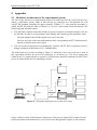
the ASCET-SD system library provides timer and flanks detectors (cf. chapter 5.4).
Experiment 4: Model the module designed in task 5 using the ASCET-SD block diagram editor.
Now, our control software is complete. Put all modules (PitmanArmDecoder, WiperDiagnosis, WiperControl) in a project together and prepare an online simulation. For this, chose the
ES1112 as target platform in the project configuration editor, define needed tasks, embed the
already existing module HWC in your project (needed for generating a hardware driver) and
generate a hardware driver with the hardware configuration editor (the hardware configuration
to use is already defined and stored in the file LabCourse_IA.hwc). Start an online experiment. Experiment with the experimental system. Use different calibration and indication elements. What happens, if you reduce the time constant Terror,max of the module WiperDiagnosis?
18
Rapid Prototyping with ASCET-SD
4 Literature
[1]
Lauber, R.; Göhner, P.: Prozessautomatisierung 1. 3. Auflage, Springer-Verlag, Berlin
Heidelberg New York, 1999
[2]
Lauber, R.; Göhner, P.: Prozessautomatisierung 2. Springer-Verlag, Berlin Heidelberg
New York, 1999
[3]
ETAS GmbH & Co. KG: ASCET-SD V3.0 User’s Guide. Stuttgart, 1999
[4]
ETAS GmbH & Co. KG: ASCET-SD V3.0 Supplement. Stuttgart, 1999
[5]
ETAS GmbH & Co. KG: ES1000 System Benutzerhandbuch. Stuttgart, 1998
[6]
Linder, Paul: Evaluierung eines rechnerunterstützten Validierungsverfahrens für komponentenbasierte ASCET-SD Spezifikationen. Diplomarbeit am IAS, Universität Stuttgart,
2000
Rapid Prototyping with ASCET-SD
19
5 Appendix
5.1 Hardware architecture of the experimental system
The IAS cockpit will serve as experimental system. The model process IAS cockpit does not constitute a stand-alone system, rather it must always be connected to a development PC with
ASCET-SD installed including the add-on package TIPExp V3.1. The principal procedure to
install ASCET-SD with the add-on TIPExp V3.1 on a PC can be taken from the manuals. The
following points should be noted:
The MS-DOS compiler and linker DIAB are used to generate executable machine code for
the ES1000. In order to avoid problems while linking, the following points should be noted:
-
The path length to the DIAB compiler may not be too long.
-
The user not only needs write authorization in the corresponding ASCET-SD directories,
but also in all directories above them.
The user needs an appropriate development PC because ASCET-SD is extremely resourcehungry (minimum requirements: P133, 64 MB RAM).
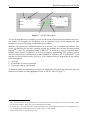
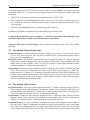
The model process is wired according to Figure 13, while the S-class door will not be used in
this experiment and does not need to be connected. A car battery or a 12V power supply unit
with at least 15 A output current is required. A 120 resistor should be connected to the ES1207
port A in order balance the corresponding CAN bus.
12 V =
S-class door
12 V =
C
A
N
"B"
12 V =
ES1000
PowerPC
experimental
computer
parallel
ES1112
Host link
C
A
N
ES1207
Port A
ES1207
Port B
ES1209
Rain sensor
Driver
Display
Pitman arm
12 V =
Control panel
ES1209
adapter
beschriftet
Wiper motor
Figure 13: Wiring the model processes of the IAS cockpit
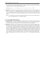
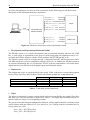
Figure 14 shows a part of the hardware architecture of the process model IAS-Cockpit relevant
to this experiment. Intermediate driver levels have been disregarded in Figure 14, because they
20
Rapid Prototyping with ASCET-SD
are of no real importance for the rest of the experiment. In the following you will find a short
description of the individual hardware components.
parallel
Development
and experimental
platform ES1000
DioA_Out1
WiperSlow
DioA_Out2
WiperFast
DioA_In1
WiperStandbyPosition
DioA_In2
Error_PA1
DioA_In3
Error_PA2
DioA_In4
Error_Overload1
DioA_In5
Error_Overload2
DioA_In6
SlowWipe
DioA_In7
FastWipe
DioA_In8
IntervalWipe
Wiper
Pitman arm
Figure 14: Hardware architecture of the experimental system
Development and Experimental Platform ES1000
The ES1000 system is a versatile development and experimental platform that uses the VME
bus. A wide range of applications in the areas of rapid prototyping and calibration can be covered with the ES1000, together with the ETAS products ASCET-SD and INCA-PC
The ES1000 system comes in a sturdy housing. A Motorola PowerPC MC604 processor with a
100 MHz clock rate is used as simulation computer (ES1112). In addition the ES1000 system in
its current configuration has a CAN interface ES1207 with two independent CAN nodes and a
digital interface card ES1209 with 20 digital inputs and 20 digital outputs.
Pitman arm
The pitman arm serves to set the desired wiper speed. Table 4 shows the corresponding signals
IntervalWipe, SlowWipe and FastWipe. Please note that the pitman arm is not debounced.
Pitman arm
Pitman arm
Pitman arm
Pitman arm
in Position 'off'
in Position 'interval'
in Position 'slow'
in Position 'fast'
IntervalWipe
Low
High
Low
Low
SlowWipe
Low
Low
High
Low
FastWipe
Low
Low
Low
High
Table 4: Truth table for the pitman arm
Wiper
The wiper is switched by a power switch which is directly controlled by the signals WiperSlow
and WiperFast from the ES1000 as depicted in Table 5. The signal WiperStandbyPosition announces when the wiper is in its beginning position.
The power switch has integrated diagnostics functions, which signal a thermal overload or other
critical failures with the signals Error_PA1 and Error_PA2. During fault-free operation the following values are valid:
Error_LE1 = NOT WiperSlow
Error_LE2 = NOT WiperFast
Rapid Prototyping with ASCET-SD
21
If the wiper is blocked, this will cause a higher current load, which is signaled by the signals
Error_Overload1 and Error_Overload2.
Wiper off
Wiper speed 'slow’
Wiper speed 'fast'
WiperSlow
Low
High
Low
Table 5: Truth table for the wiper
WiperFast
Low
Low
High
22
Rapid Prototyping with ASCET-SD
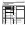
5.2 ASCET-SD Descriptive Elements
5.2.1
Primitive Elements
OBJEKT
receive_message
Messages
Icon
Blockschaltbild
EIGENSCHAFTEN
Protected variables (only scalar)
Only usable in modules
Normal variables, i.e. unprotected elements during preemptive task changes.
Zero to two dimensional
Contain a value type cont, disc oder log
depending on the model type.
Zero to two dimensional
Standard performance curves
Fixed performance curves
Group performance curves
Standard performance maps
Fixed performance maps
Group performance maps
send_message
receive_send_message
continuous
logic
signed discrete
unsigned discrete
Variablen
Array
(eindimensional)
Matrix
(zweidimensional)
Konstanten
Parameters
Applizierbare
Größen
Performance curves
Performance maps
Rapid Prototyping with ASCET-SD
23
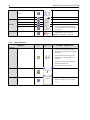
5.2.2 Operators
OBJECT
Addition
Icon
CHARACTERISTICS
Block chart
Maximum of 5 inputs with Argument
size.
Maximum of 5 inputs with Argument
size.
Number of inputs can be freely
defined.
a>x>b
-> if the condition is fulfilled
-> output = ‘true‘
n logical inputs top
n+1 inputs left
1 output right
all inputs and outputs must be of the
same type
Integer input top, which defines
which input (left) from the top will
be looped through.
Multiplication
Subtraction
Arithmetical
operators
Division
Sign
Amount
Minimum
Maximum
And
Logical
operators
Or
Not
Larger than
Interval (between)
Smaller than
Comparators
Larger/equal to
Smaller/equal to
Equal
Unequal
Operators
for the
Boolean
data flow
Mux
Case
If
Operators
to control
the control
flow
If-then-else
While
24
Rapid Prototyping with ASCET-SD
Switch
Break
True
False
Literals
If the digits to the right of the decimal are disregarded while editing
literals then they will be interpreted
as integers.
Integrating elements can be inserted
independent of the time space.
newValue = oldValue + k*in+dT
0.0
1.0
dT Operator
5.2.3
Other Elements
OBJECT
Icon
CHARACTERISTICS
Block chart
Protects memory areas for a certain
time in order to prevent variables
from being changed by interrupting
processes.
Concept of the operating system
ERCOSEK to prevent data inconsistency.
A global variable with semaphore
protection mechanism.
Comparable with a message
Self
Allows for an object to call itself.
Hierarchy
Serve for a clear overview.
Have no influence on code generation.
Resource
Rapid Prototyping with ASCET-SD
25
5.3 Operators (C or Java syntax)
5.3.1 Arithmetical Operators
Operator
Meaning
Example
+
*
/
%
Addition
Subtraction
Multiplication
Division
Modulo
3 + 4
5 - 7
5 * 5
14 / 7
20 % 7
5.3.2 Assignments
Expression
Meaning
x += y
x -= y
x = x + y
x = x - y
x *= y
x = x * y
x /= y
x = x / y
5.3.3 Logical Operators
Operator
==
!=
<, >
<=, >=
&&
||
Meaning
Equal
Unequal
Smaller than, larger than
smaller or equal, larger or
equal
And
Or
Example
x == 3
x != 3
x < 3, x > 3
x <= 3, x >= 3
(x > 0) && (x < 1)
(x > 0) || (x < 1)
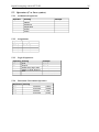
5.3.4 Increment / Decrement Operators
Expression Meaning
x++
x = x +
x-x = x –
++x
x = x +
--x
x = x -
1,
1,
1,
1,
Increment
Decrement
Inrement
Decrement
(postfix)
(postfix)
(prefix)
(prefix)
26
5.4 Subset of the ASCET-SD system library
Rapid Prototyping with ASCET-SD
Rapid Prototyping with ASCET-SD
27
28
Rapid Prototyping with ASCET-SD
Rapid Prototyping with ASCET-SD
29