1
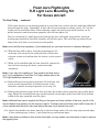
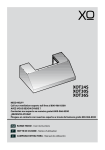
FRESH AERO FlightLights
TLR Light Lens Mounting Kit
For Sonex Aircraft
User Manual
Where Imagination Meets Innovation
The
Steelebrook Group
Fresh Aero FlightLights
TLR Light Lens Mounting Kit
For Sonex Aircraft
Thank you for purchasing the Fresh Aero FlightLights TLR Lens Mounting Kit for Sonex
Aircraft. We’re confident you will be pleased with this innovative and easy to install Sonex
wing leading edge lens and mount.
This lens mounts with just two retainers, top and bottom and conforms with the wing leading
edge profile. The one piece retainers are precision machined with threaded holes for easy
screw mounting.
This detailed step by step manual and the included templates will guide you easily through
the entire leading edge cut-out and lens install process.
The lens kits include everything you'll need to mount the lens - the lens, retainers, drill,
screws and foam seal.
Please contact us if you have any installation questions or feedback.
Table of Contents
Lens Mounting Kit Description and Features ………..…………….………. 2
Warnings and precautions …….……………………………………..………. 3
Legal Notices and Warranty …………………………………………………. 4
Parts and Tools Required ……………………………………………………. 5
Installing the Lens Kit ……………………………..………………………….. 5
Cutting the Lens Opening ……………………………………………………. 5
Mounting the Lens Retainers …………….…………………………..……… 7
Fitting the Lens ……………………………………..…………………………. 8
The Final Fitting .………………………………………………………………11
Fresh Aero Contact Information ………………………….….………………13
Appendix ………………………………………………………………………14
Fresh Aero Aviation, 1142 Roseland Drive, Columbia, TN 38401
Phone: (931) 381-6092
(888) 581-4952
(931) 215-8801
Email: [email protected]
www.freshaero.com
2
Fresh Aero FlightLights
TLR Light Lens Mounting Kit
For Sonex Aircraft
Study and save this manual
n!!
n
WARNING
Read this entire manual before starting your lens installation and refer to it during
installation. Make sure you understand the instructions and safety precautions in
this manual. Failure to follow all the instructions in this manual can cause personal
injury. Keep this manual and your invoice in a safe place for future reference. Do
not use this product if you do not understand all the instructions and safety
precautions in this manual. If this product is used without observing the information
given under this symbol, injury may result.
Fresh Aero TLR Light Lens Mounting Safety Warnings and Precautions
Warning: Always adhere to the following safety precautions when using this product.
n Always keep the work area clean. Cluttered areas invite accidents and possible injuries.
n Stay alert and concentrate on safety.
n Never perform aircraft maintenance if under the influence of alcohol or drugs. Read
warning labels on prescriptions you are taking to determine if your judgment or reflexes
will be impaired while taking these drugs.
n Always maintain proper footing and balance during the lens install process. Ask for help if
necessary. Awkward positions and/or improper bending can cause falls, personal injury and
equipment damage.
n Always locate aircraft on a level surface and chock aircraft tires to prevent movement.
n Use proper safety equipment and precautions when cutting the lens mounting hole in the
the wing(s). Hole will have sharp edges after cutting so be sure to de burr the edge of the
hole completely to avoid abrading your hands on the edge.
Warning: The warnings, precautions and instructions discussed in this manual cannot cover all
possible conditions and situations that may occur. It must be understood by the operator that
common sense and caution are factors that cannot be built into this mounting kit and must be
supplied by the person or persons using this product.
If you have questions regarding the installation or operation of this TLR Light Lens Mounting Kit
or just need another manual, please contact Fresh Aero at the contact numbers or e-mail
address on the last page of this manual. Our manuals are also on our web site,
www.freshaero.com, in PDF format.
3
Fresh Aero FlightLights
TLR Light Lens Mounting Kit
For Sonex Aircraft
Other Legal Notices
Fresh Aero makes no representations or warranties regarding any damages, injuries or benefit expected
by using this unit lawfully, or any request from a third person, which are caused by the inappropriate use
of this product.
Disclaimer of Warranty
Fresh Aero makes no representations of warranties, either expressed or implied, by or concerning any
content of these written materials and in no event shall be liable for any implied warranty for any
consequential, incidental or indirect damages (including but not limited to damages for loss of business
profits or business interruption) arising from the use or inability to use these written materials or
equipment. No liability is assumed with respect to the use of the information contained in these written
materials, or for damages resulting from the use of the information contained therein.
Copyright 2013
Fresh Aero reserves all rights to this manual including the right to alter the features and contents of this
publication without obligation or advance notice.
The Fresh Aero FlightLights TLR Light Lens Mounting Kit
3 year Limited Warranty
Fresh Aero makes every effort to provide high quality and durable products to the aviation community and
warrants to the original purchaser that this product is free from defects in materials and workmanship for
the period of 3 years from the date of purchase. This warranty does not apply to damage due directly or
indirectly to misuse, abuse, negligence or accidents; repairs or alterations outside our facilities; or to lack
of maintenance. Also, this warranty does not cover scratched or abraded lenses due to impact or other
abrasions. We shall in no event be liable for death, injuries to persons or property or for incidental,
contingent, special or consequential damages arising from the use of our product. Some states do not
allow the exclusion or limitation of incidental or consequential damages, so the above limitation of
exclusion may not apply to you.
To take advantage of this warranty, the product or part must be returned to us with transportation charges
prepaid. Proof of purchase date and an explanation of the defect or problem must be included with the
product. If inspection verifies the defect, we will either repair or replace the product at our discretion or
may elect to refund the purchase price price if we cannot readily and quickly provide you with a
replacement. We will return the repaired or replaced product at our expense, but if we determine there is
no defect, or that the defect resulted from causes not within the scope of our warranty, then the
purchaser must bear the cost of returning the product.
This warranty gives you specific rights and you may also have other rights which vary from state to state.
4
Fresh Aero FlightLights
TLR Light Lens Mounting Kit
For Sonex Aircraft
Installing the TLR Light Lens
Parts and Tools Required:
●
●
●
●
●
●
●
●
TLR lens and lens mounting kit
This manual with all templates
Tool for cutting lens opening in leading edge
Files/de burring tool for de burring lens opening
“Dremel” tool or other acrylic plastic cutting tools
Small Philips head screwdriver
Drill motor, 1/8 inch drill
Small clamps, felt tip marker, masking tape, duct tape
n Locate the aircraft on a flat, level, dry and debris free surface and chock tires to prevent
movement.
n The following procedures assume the wing leading edge skin is mounted and secure.
n Determine the mounting location of your leading edge light and lens. The light and lens
must be centered between wing ribs. We recommend an outboard location. There is very
little wing loading and skin bending moments at the outboard locations. The Sonex OneX
may be an exception to this recommendation as the section inboard of the wing fold is a
separate skin section and is inherently rigid.
1. Cutting the Lens Opening
Note: The templates are located in the appendix at the end of this manual. The templates are
an integral part of the lens installation. We recommend that you make actual size copies of
these templates and keep them in a safe place in case the originals are damaged or misplaced.
1.1 Find the Lens Template (T1) in the appendix. Use scissors to cut out the lens opening
(red line). Cut as accurately as possible. Attach the template to the wing leading edge
at the selected location (between ribs) using the guide lines on the template to position
it correctly between the rivet lines on the wing (photo 1). Determine the apex of the
wing leading edge (forward
most surface on the leading
Apex
edge (see note below). Draw
short horizontal lines on the
apex at each side or the
11
template with a fine tip felt
marker.
1
5
Fresh Aero FlightLights
TLR Light Lens Mounting Kit
For Sonex Aircraft
Cutting the Lens Opening … continued
Note: A good way to determine the apex of the the leading
edge is to look down the leading edge (like sighting a gun)
and look for the forward most point. Draw the horizontal lines
at this point.
Note: if the aircraft is painted, just apply a short strip of
painter’s tape to the leading edge at both sides of the
template and draw the horizontal line on the tape.
1.2 Align the horizontal apex guide line on the template
with the apex and align the template vertical rivet
guide lines with the wing rivet lines.
2
1.3 Use masking tape to secure the template (photo 1).
1.4 Measure from the top horizontal line of the template
(at both sides) back to the the leading edge seam at
the spar. The actual dimension isn’t critical but the
distance at each side must be equal. This ensures
that the lens opening is square with the leading
edge. Very Important.
Important: If you are using the Fresh Aero TLR Light and
brackets, they are designed to center the light between the rib
rivet holes and will align with the above template location
correctly. If you’re using other lighting, you need to confirm
that the lens opening will align correctly with the lights you
use. If not, move the template to correspond with the light
centerline.
13
4
1.5 Use a felt tip marker to trace a line on leading edge
of the wing using the lens opening on the template as
a guide (photo 1).
1.6 Remove the template and cut out the lens opening on
the wing with your selected tool (photo 2). Cut
slightly away from the line to allow room for error.
Finesse the opening with files or other hand tools to
achieve the final dimension. Deburr and smooth edge
of opening (photo 3).
6
5
Fresh Aero FlightLights
TLR Light Lens Mounting Kit
For Sonex Aircraft
Cutting the Lens Opening … continued
Note: We recommend using a power abrasive cutting wheel or vibrating blade to make the initial cut. Pilot
holes and a hack saw blade will also work, if you have the patience. We don’t recommend using tin snips as
these may leave kinks in the aluminum.
Warning: To avoid hand abrasions, don’t leave burrs on the
edges of the opening. Your hands will be in and out of this
opening many times. Consider using masking tape on the edges
to protect your hands.
2. Mounting the Lens Retainers
2.1 Re-attach the lens (T1) template and locate the upper
lens retainer (marked with a “T”) on the skin just above
the opening (the upper retainer has an internal radius
on each end to position the lens). The template will show
the proper retainer location and orientation. Just locate
the retainer within the outline on the template and
clamp it to the skin with “C” clamps or another secure
clamping device (photo 5).
6
6
Caution: the retainer will be used to spot drill the attach holes for mounting the retainer. Be sure the retainer
is properly located on the template with the milled “pocket” facing up and facing the opening (photo 5). The
edge of the the retainer must be parallel to the opening edge and 3/8 inch (9.5 mm) from the lens opening.
It’s very important to maintain the spacing and parallelism.
Also confirm that the retainer is tight and will not move out of position when drilling the holes.
2.2 Use the included #44 drill to drill four holes in the skin using the retainer holes as guides (photo 6).
Caution: Use extra care to keep the drill perpendicular to the holes in the retainer. Do not “wiggle” the drill.
The retainer holes are threaded and a misaligned drill will damage the threads (photo 6).
2.3 Use the above procedure to locate and drill the bottom retainer mounting holes below the lens
opening. The bottom retainer is milled without the radii but is mounted exactly as above with
milled side out and facing the opening. The edge of the the bottom retainer must be parallel to
the opening edge and 3/8 inch (9.5 mm) from the lens opening. It’s very important to maintain
the spacing and parallelism.
2.4 Remove the retainers and lens opening template. Enlarge all 8 holes with a 1/8 inch drill and deburr the
holes. Finish and deburr opening with files or other finishing tools until edges are smooth and burr free.
Take care not to mar or abrade the leading edge surface, especially if the aircraft is finished.
2.5 Apply masking tape to the edge of the opening to protect your hands and the acrylic lens.
7
Fresh Aero FlightLights
TLR Light Lens Mounting Kit
For Sonex Aircraft
3. Fitting the Lens
3.1 Cover the lens with painter’s tape on both sides to protect it from
abrasion during the cutting and fitting procedure (photo 9).
Layer the tape from both top and bottom edges, moving to the
center. In a future step, the tape will be removed, center first,
and used as a viewing window during final assembly. Do this on
both sides of lens.
Note: one edge of the lens is marked “top”. Just transfer this mark to the
tape on the same edge.
7
3.2 Add a strip of tape to the upper and lower outside edge of lens
wing opening and mark a center line using the original lens
opening template.
6 3.3 Make a “handle” from duct tape and attach it to the lens, wrapping the ends of the tape around the top and bottom of the lens
(photo 7). This “handle” will be used multiple times during the
fitting process.
Hint: Use an additional strip of tape on the inside of the “handle”, sticky
side to sticky side, to prevent your hands from sticking to the tape
(photo 7).
3.4 Mark the centerline of the lens on the tape handle at the top
and bottom edge of the lens (photo 7).
8
3.5 Insert the lens through the lens opening with the top edge
facing up. Squeeze the lens slightly to pass it through the hole.
Center the lens by matching the centerlines on the wing and
lens, top and bottom. Confirm that top and bottom of lens is
centered when pulling on the tape handle (photo 7, tape on
lens not shown for clarity).
3.6 While pulling on the tape handle, trace the opening on the
painters tape with a pencil or fine tip felt marker. This tracing
will be used to trim the top and bottom edges for fitting lens to
retainers. Release the lens and pull it against opening again to
confirm the correct location.
9
3.7 Remove the lens and remove the tape handle from the lens.
Store the handle for future use.
8
Fresh Aero FlightLights
TLR Light Lens Mounting Kit
For Sonex Aircraft
Fitting the Lens … continued
3.8 Locate the Lens Trimming Template (T2) in the appendix. You will use the center section as the
trim guide. Draw a pencil line on the lens 5/8 inch from the top lens opening tracing and parallel
with the tracing (towards the top edge). Cut out the template section depicted by the red line and
align the upper red edge (labeled on template)
with the pencil line just drawn. Secure the cutout
to the lens with tape. The top line on the template (with the radii) is the line you will use to
trim the upper edge of the lens.
3.9 Cut or grind the top edge of the lens to conform to
the above template top line including the radius
at both ends (photos 8, 9, 10, 11, 12). Provide 1/32
inch spacing between lens and radius on both
sides to allow for lens expansion.
9
10
Caution: Use proper acrylic plastic cutting and stock
removal procedures when trimming lens. Do not use
snips or any other tool that might crack or damage the
acrylic.
Also, during the lens trimming process, it’s better to trim
conservatively and then slowly remove access material
with subsequent adjustments.
Note: Drawing D1 in the Appendix will help clarify the
following steps.
3.10 When the upper edge of the lens is trimmed
properly, mount the upper lens retainer to the
inside of the skin through the lens opening
using the drilled holes and the included ¼ inch
long 4-40 screws. The milled “pocket” must be
facing towards the opening and the skin. This
forms a pocket between the skin and retainer to
accept the lens. Gently tighten the screws.
11
3.11 Re-attach the tape handle as before and mount
the lens again. With this mounting, rotate the
lens bottom edge aft until the upper profiled edge
12
can be inserted in the milled pocket of the top
retainer. Confirm that the lens is centered using
the center marks and traced lines on the lens before moving to the next step.
9
Fresh Aero FlightLights
TLR Light Lens Mounting Kit
For Sonex Aircraft
Fitting the Lens … continued
3.12 Pull on the bottom of the tape handle with one hand and rotate and guide the lens into the top
retainer pocket until seated. Check the center marks and tracings to confirm lens is fully
engaged in the pocket of the top retainer. If trimming is required, remove lens and use a file or
sanding device to complete final finessing of the upper edge. Reinstall the lens.
3.13 With tape handle in place, lens seated in the top retainer pocket and the center lines aligned,
pull the bottom of the handle against the lens opening with moderate force which should rotate
lens slightly and snug front lens profile to the leading edge skin. Gently tighten the upper
retainer screws.
Note: If a friend or family member is available to help this
would be a good time to ask for assistance.
Very Important: Pull consistently on the lens to confirm
that the lower trace line is still positioned at the opening
cutout. If not, draw a new line with a different color pencil or marker. Release and apply pull force again to check
for repeating results. THIS STEP WILL AFFECT FINAL
APPEARANCE AND FIT.
3.14 Remove lens and install lower retainer with two
of the four included 5/8 inch long 4-40 screws in
the two inboard holes. Push back slightly on the
retainer and lightly tighten the screws. Use a
scale or thin measuring tool to measure the distance from the rear of the retainer’s lens pocket
(the back of the pocket) to the edge of the lens
opening on the wing.
13
Lower retainer raised and
leaning back
3.15 Using the line on the lens identified in step 3.6,
add the dimension obtained in step 3.14, aft of
this line (towards the rear of the lens), and draw a line aft and parallel to the original line. The
added distance should be about 5/8 inch if the lower retainer was installed properly.
3.16 Trim the lens bottom edge to match the line drawn in step 3.15. There is no profile to match
during this operation, just a straight cut as the lower retainer does not have the lateral guides.
Caution: When trimming lens, be sure to leave additional material for fitting! Once material is removed, you
can not replace it We recommend leaving at least 1/16 inch extra material for first lower retainer trial fit.
Also additional material will allow for small discrepancies during roughing operation and for correcting any
lower retainer misalignment.
10
Fresh Aero FlightLights
TLR Light Lens Mounting Kit
For Sonex Aircraft
Fitting the Lens … continued
Caution: Use proper acrylic plastic cutting and stock removal procedures when trimming lens. Do not use
snips or any other tool that would crack or damage the acrylic.
Remember, during the lens trimming process, it’s better to trim conservatively, then slowly remove access
material with subsequent adjustments.
3.17 Loosen the bottom retainer screws until they are flush with the retainer top surface. Push up on
lower retainer and lean it as far aft as you can (photo 13) If retainer falls back down, use a
strip of tape across the screw heads and skin to hold the retainer up.
4. The Final Fitting
4.1 Remove a few top layers of tape from the apex of the lens for viewing through the lens in
subsequent steps.
4.2 Attach the tape handle to lens once again, making sure edges of the tape are folded around the
ends of lens surface for better adherence. You might want to construct a new handle if your
current one has lost its holding power. This will eliminate the any frustration that may occur if
tape slips off during the following steps.
4.3 With the upper lens retainer in place (upper retainer screws may need to be loosened slightly to
facilitate lens insertion), and with lower retainer raised, carefully install the lens, confirming that
lower edge of lens fits between the lower wings skin and raised lower retainer (Photo 13). The
edge of lens should be tight against the threads of the screws. This step allows the lens lower
14
edge to be rotated aft and provide clearance for the lens upper ledge to be inserted back under
the upper retainer’s retaining pocket.
Note: make sure the side to side center lines at top are aligned before rotating lens into retainer pocket.
4.4 Confirm that the lens top edge is properly seated into the the top retainer pocket and that bottom
edge of lens is located between lower retainer and skin by viewing the retainers through the lens.
4.5 Pull down on the lower retainer using the two 5/8“ screws, confirming that the bottom of the
retainer mates tightly with the skin of the wing. If not seated properly, pull the lens forward
with the handle to seat the retainer There are two indicators to look for – a “through the lens”
visual inspection of the retainer mating tightly against the skin and the perpendicular
orientation of the screws attached to the retainer at the bottom of the wing.
Note: External lighting may help to confirm the retainer to lens fit between the retainer pockets and skin.
11
Fresh Aero FlightLights
TLR Light Lens Mounting Kit
For Sonex Aircraft
The Final Fitting … continued
If the lower retainer is not mating properly on top of the lens, remove the lens and trim additional
material from the edge. Remember, it may take several attempts to obtain correct “fit” but the
results will be worth the effort. After trimming, repeat the above steps until retainer can be
pulled into place and drawn down properly over the lens (photo 14).
Don’t be concerned if a small gap exists between the lens and inside wing surface, the foam
sealing tape installed in the final assembly will fill this space. This said, the gap should be no
larger than 3/32 inch at any location on the profile.
Note: we do sell the lens separately, if you inadvertently cut your lens too short or otherwise damage it.
4.6 With the lens still in place, start the remaining two 5/8
inch long 4-40 screws in the outboard holes of the lower
retainer screws and confirm that the screws can be started
easily.
4.7 When you’re satisfied with the lens install fit, remove the
lens by first removing the lower retainer bracket
completely.
Note: If your light isn’t installed yet, This would be an ideal time to
do it. If you purchased a Fresh Aero TLR Light, please refer to the
TLR Light installation manual now.
4.8 Reinstall lower lens retainer using two 5/8 inch long 4-40
screws in the inboard holes. Position retainer in the
extended, upward, leaning aft position as in step 3.16.
14
Properly seated
Lens and retainer
4.9 Remove the protective tape on the lens and clean the inside surface removing any residue from
tape. Mount the included foam tape on the forward curved edges of the lens with about half the
width of the tape extended over the edges.
Note: Additional foam tape is supplied for fitting on the upper and lower surfaces of the lens, just aft of the
top and bottom lens opening, but this may be a tight fit. Consider cutting the foam strip in half for less bulk. If
you’re satisfied with the lens to skin seal without the foam, top & bottom, just omit it.
4.10 Attach lens handle once more, directly on the lens front surface. Do not wrap tape around edges
of lens and keep tape at least ½ inch from the top and bottom edges.
Note: If tape does not adhere to lens on this final install, you may need to use fresh piece of tape to improve
the gripping force.
12
Fresh Aero FlightLights
TLR Light Lens Mounting Kit
For Sonex Aircraft
The Final Fitting … continued
4.11 Carefully maneuver the lens into place side to side and rotate lens into the upper retainer.
Caution: The lens does not have the protective coating now, so be extra careful when inserting the lens into
the opening to prevent abrasion. Squeeze the lens gently to clear the opening.
4.12 Continue to pull on the handle while positioning lower retainer into place. If retainer will not sit
on bottom skin properly, additional pull force may be needed to move lens forward due to the
foam seal resistance. Additional lens trimming may be necessary.
4.13 When the lens and lower retainer are properly seated, insert the two remaining 5/8” screws in
the outboard lower retainer holes and tighten all four screws.
4.14 Tighten the four upper retainer screws.
Caution: To prevent stripping the retainer threads, do not over tighten the retainer screws. These screws
should not back out. To prevent this, just use a little service removable “Loc-Tite” on the threads.
Note: If you prefer to mount the lens retainers with flat head screws (not included), retainers can be
countersunk slightly to accommodate the necessary “skin bumps” . If you do this, take care not to
countersink too deeply, destroying the retainer threads.
4.15 Remove the tape from lens and clean off residue.
4.16 Installation procedure is complete. CONGRATULATIONS!
Thanks again for purchasing the Fresh Aero Lens Kit for Sonex Aircraft. We have tried to make this kit and
manual as user friendly as possible. We always welcome your comments and suggestions for future
revisions.
Fresh Aero Aviation, 1142 Roseland Drive, Columbia, TN 38401
Phone: (931) 381-6092
(888) 581-4952
(931) 215-8801
Email: [email protected]
www.freshaero.com
LensMountKitRev1013
13
Fresh Aero FlightLights
TLR Light Lens Mounting Kit
For Sonex Aircraft
Appendix
Use the following templates to facilitate your wing leading edge lens installation
procedure. The procedure steps will identify the correct template to use and how to
apply the templates.
Lens Opening Cutout Template …………………. T1
Lens Trimming Template …………………………. T2
Lens Assembly Profile Template .………………. D1
14