1
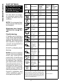
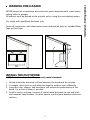
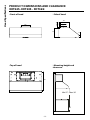
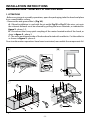
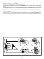
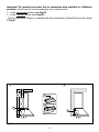
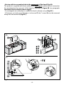
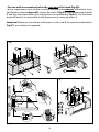
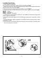
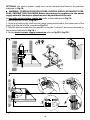
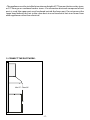
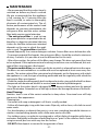
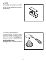
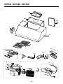
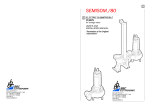
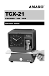
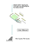
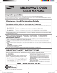
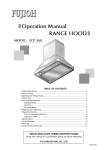
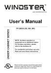
XOT24S
XOT30S
XOT36S
NEED HELP?
Call our ventilation experts toll free al 800-966-8300
AVEZ-VOUS BESOIN D’AIDE ?
Contactez nos experts au numéro gratuit 800-966-8300
¿NECESITA AYUDA?
Póngase en contacto con nuestros expertos a través del número gratis 800-966-8300
USA RANGE HOOD - User instructions
F
HOTTE DE CUISINE - Notice d’utilisation
E
CAMPANA EXTRACTORA - Manual de utilización
XO Hood Warranty
Proof of original purchase date and invoice is needed to obtain
service under warranty.
What is covered
Limited 2 Year Warranty.
For 2 years from the original date of purchase, we will provide,
free of charge, parts and service labor in your home to repair or
replace any part of the hood that fails because of a manufacturing
defect.
The warranty is extended to the original purchaser for products
purchased for ordinary home use in North America.
Should you require service for your XO product call a product
service specialist at 800.966.8300
What is not covered
Improper Installation.
Service trips to the home to teach you how to use the product.
Resetting circuit breakers.
Damage caused after delivery.
EXPECT MORE FROM XO
When buying any XO appliance
you can be confident
you have purchased a high quality,
innovative, and stylish product,
from a company who cares about you
ENGLISH
USA
IMPORTANT SAFETY INSTRUCTIONS
FOR RESIDENTIAL USE ONLY
READ AND SAVE THESE INSTRUCTIONS
PLEASE READ ENTIRE INSTRUCTIONS BEFORE PROCEEDING.
IMPORTANT: Save these Instructions for the Local Electrical Inspectors use.
INSTALLER: Please leave these Instructions with this unit for the owner.
OWNER: Please retain these instructions for future reference.
Take care when using cleaning agents or detergents.
Suitable for use in household cooking area.
WARNING - To reduce the risk of fire or electric shock, do not use this fan with any
Solid-State Speed Control Device.
CAUTION - To reduce risk of fire and to properly exhaust air, be sure to duct air outside – Do not vent exhaust air into spaces within walls or ceilings or into attics, crawl
spaces, or garages.
CAUTION - For general ventilating use only. Do not use to exhaust hazardous or explosive materials and vapors.
CAUTION - To avoid motor bearing damage and noisy and/or unbalanced impellers,
keep drywall spray, construction dust, etc. off power unit.
CAUTION - Please read specification label on product for further information and
requirements.
WARNING – TO REDUCE THE RISK OF FIRE, ELECTRIC SHOCK, OR INJURY TO PERSONS,
OBSERVE THE FOLLOWING:
A. Use this unit only in the manner intended by the manufacturer. If you have questions,
contact the manufacturer.
B. Before servicing or cleaning unit, switch power off at service panel and lock the service disconnecting means to prevent power from being switched on accidentally.
When the service disconnecting means cannot be locked, securely fasten a prominent warning device, such as a tag, to the service panel.
WARNING - TO REDUCE THE RISK OF A RANGE TOP GREASE FIRE:
A. Never leave surface units unattended at high settings. Boilovers cause smoking and
greasy spillovers that may ignite. Heat oils slowly on low or medium settings.
B. Always turn hood ON when cooking at high heat or when flambeing foods ( i.e.
-3-
Crepes Suzette, Cherries Jubilee, Peppercorn Beef Flambè ).
C. Clean ventilating fans frequently. Grease should not be allowed to accumulate on
fan or filter.
D. Use proper pan size. Always use cookware appropriate for the size of the surface
element.
E. Keep fan, filters and grease laden surface clean.
F. Use high range setting on range only when necessary.Heat oil slowly on low to medium setting.
G. Don’ t leave range unattended when cooking.
H. Always use cookware and utensils appropriate for the type and amount off food being prepared.
WARNING – TO REDUCE THE RISK OF INJURY TO PERSONS IN THE EVENT OF A RANGE
TOP GREASE FIRE, OBSERVE THE FOLLOWINGa:
A. SMOTHER FLAMES with a close-fitting lid, cookie sheet, or metal tray, then turn off
the burner. BE CAREFUL TO PREVENT BURNS. If the flames do not go out immediately,
EVACUATE AND CALL THE FIRE DEPARTMENT.
B. NEVER PICK UP A FLAMING PAN – You may be burned.
C. DO NOT USE WATER, including wet dishcloths or towels – a violent steam explosion
will result.
D. Use an extinguisher ONLY if:
1. You know you have a Class ABC extinguisher, and you already know how to operate
it.
2. The fire is small and contained in the area where it started.
3. The fire department is being called.
4. You can fight the fire with your back to an exit.
aBased on “kitchen firesafety tips” published by NFPA
Proper maintenance of the Range Hood will assure proper performance of the
unit.
INSTALLATION INSTRUCTIONS
WARNING – TO REDUCE THE RISK OF FIRE, ELECTRIC SHOCK, OR INJURY TO PERSONS,
OBSERVE THE FOLLOWING:
A. Installation work and electrical wiring must be done by qualified person(s) in accordance with all applicable codes and standards, including fire-rated construction.
B. Sufficient air is needed for proper combustion and exhausting of gases through the
flue (chimney) of fuel burning equipment to prevent back drafting. Follow the heating equipment manufacturer’s guideline and safety standards such as those published by the National Fire Protection Association (NFPA), and the American Society
for Heating, Refrigeration and Air Conditioning Engineers (ASHRAE), and the local
code authorities.
C. When cutting or drilling into wall or ceiling, do not damage electrical wiring and
other hidden utilities.
-4-
D. Ducted fans must always be vented to the outdoors.
E. This unit must be grounded.
WARNING - TO REDUCE THE RISK OF FIRE, USE ONLY METAL DUCTWORK.
WARNING - UNDER CERTAIN CIRCUMSTANCES DOMESTIC APPLIANCES MAY BE DANGEROUS.
A. Do not check filters with hood working.
B. Do not touch the lamps after a prolonged use of the appliance.
C. No food must be cooked flambè underneath the hood.
D. The use of an unprotected flame is dangerous for the filters and could cause fires.
E. Watch constantly the fried food in order to avoid the cooking oil flares up.
F. Before performing any mainteinance operation, disconnect the hood from the electrical service.
The manufacturers will not to accept any responsability for eventual damages, because of failure to observe the above instructions.
-5-
Installation Preparation
DUCT FITTINGS:
This Hood Must Use an
6" Round Duct. It Can
Transition to 3-1/4" x 10"
or 3-1/4" x 12" Duct.
Use this chart to compute maximum permissible
lengths for duct runs to
outdoors.
NOTE: Do not exceed maximum permissible equivalent lengths!
Maximum duct length:
100 feet for range hoods.
Flexible ducting:
If flexible metal ducting is
used, all the equivalent feet
values in the table should be
doubled. The flexible metal
duct should be straight and
smooth and extended as
much as possible.
DO NOT use flexible plastic
ducting.
NOTE: Any home ventilation
system, such as a ventilation
hood, may interrupt the
proper flow of combustion
air and exhaust required
by fireplaces, gas furnaces,
gas water heaters and other
naturally vented systems. To
minimize the chance of interruption of such naturally
vented systems, follow the
heating equipment manufacturer’s guidelines and
safety standards such as
those published by NFPA.
Duct
Piece:
Equivalent
Dimensions: Number
Length*:
Round, straight
1 ft. (per foot
lenhgth)
3-1/4" x 10"
straight
1 ft. (per foot
lenhgth)
90° elbow
12 ft.
45° elbow
7 ft.
3-1/4" x 10"
3-1/4" x 12"
90° elbow
14 ft.
10 ft.
3-1/4" x 10"
3-1/4" x 12"
45° elbow
8 ft.
6 ft.
3-1/4" x 10"
3-1/4" x 12"
90° elbow
33 ft.
24 ft.
6" round to
rectangular
2 ft.
Rectangular to
8" round
2 ft.
3-1/4" x 10"
3-1/4" x 12"
6" round to
rectangular
transition 90°
elbow
4 ft.
4 ft.
3-1/4" x 10"
3-1/4" x 12"
Rectangular to
6" transition
90° elbow
4 ft.
4 ft.
Round wall
cap with
dramper
24 ft.
3-1/4" x 10"
3-1/4" x 12"
Rectangular
wall cap with
dramper
24 ft.
18 ft.
Round roof
cap
33 ft.
*Actual length of straight duct plus duct
fitting equivalent. Equivalent length of duct
pieces are based on actual tests conducted
by GE Evaluation Engineering and reflect
requirements for good venting performance
with any ventilation hood.
-6-
Quantity
Used:
Total
Equivalent
Length:
Total Duct Run =
NEVER exhaust air or terminate duct work into spaces between walls, crawl spaces,
ceiling, attics or garages.
All exhaust must be ducted to the outside, unless using the recirculating option.
Use single wall rigid Metal ductwork only.
Fasten all connections with sheet metal screws and tape all joints w/ certified Silver
Tape or Duct Tape.
INSTALL THE DUCTWORK:
NOTE: To reduce the risk of fire, use only metal ductwork.
1.
2.
3.
4.
Decide where the ductwork will run between the hood and the outside.
A straight, short duct run will allow the hood to perform most efficiently.
Long duct runs, elbows, and transitions will reduce the performance of the
hood. Use as few of them as possible.
Install a roof or wall cap. Connect 6" round metal ductwork to cap and work
back towards hood location. Use duct tape to seal the joints between ductwork
sections.
-7-
Installation - Ducting Options
WARNING FIRE HAZARD
› Front of hood
› Side of hood
������
���
���
��������
������
���
› Top of hood
��
Hood Specifications
Product dimensions and clearance
XOT24S -XOT30S - XOT36S:
› Mounting height and
clearance:
���
�������������������
�����������������
���
-8-
Installation Instructions
Installation - Vented to the outside
1. Attention!
- Before carrying out assembly operations, open the packaging, take the hood and place
it on a comfortable surface.
- Remove the anti-grease filter/s (Fig.1A).
A - If hood installation is used with the air outlet Fig.1B or Fig.1C, the wires set-up in
the relevant fairleads must be released by pulling the lever outwards, as indicated in
figure 2 - phase 1-2.
B - Disconnect the 6-way quick coupling of the motor located inside of the hood, as
show in figure 2 - phase 3.
C - The wires positioned inside of the hood are fasted with a cable tie. Cut the cable tie
as shown in figure 2 - phase 4.
Once transformation operations have been terminated, reassemble the components fol-
�
�
�
�
�
�
�
�
�
�
�
�
�
�
Fig.1
-9-
lowing the steps in reverse (Fig.2).
In this way it will be easier to manoeuvre the unit.
- If the appliance id to be mounted in DUCTING version, prepare the air evacuation
hole.
- It is recommended to use an air evacuation pipe with the same diameter as the air outlet
flange. The use of a reduction could decrease product performance and increase noise.
I M P O R TA N T - T h e r a n g e h o o d m u s t b e s e c u r e d t o w a l l
studs or use drywall anchors capable of supporting 75 lbs.
�
�
�
�
���
�
Fig.2
- 10 -
�
Attention! This product envisions the air evacuation hole available in 2 different
positions, which can be used according to your requirements;
1 – in the upper part of the hood Fig.3A.
2 – in the rear part of the hood Fig.3B.
- The air evacuation flange is supplied with the rectangular shape X and circular shape
Y (Fig.3).
�
�
�
�
�
�
Fig.3
- 11 -
• Version with air evacuation hole in the upper part of the hood (Fig.4A):
This product is supplied with the air outlet in the upper part and the electric connection
box positioned in the rear part of the hood, as indicated in figure 4B (see paragraph:
connection to the electric power supply).
- If a rectangular air outlet pipe is used E, the hood is already set-up (Fig.4A.1).
- If, however, a circular air outlet pipe is to be used F, the 7 screws H must be removed
along with the bracket X (Fig.4A.2).
�
�
�
�
�
�
�
�
�
�
�
�
�
�
�
Fig.4
- 12 -
�
• Version with air evacuation hole in the rear part of the hood (Fig.5A):
- If your requirements envision the use of the air outlet in the rear part of the hood (carry
out all phases shown in figure 5B), remove the screws I (Fig.5A.1) that fix the motor bracket
Y and turn the entire motor unit and position it as indicated in Fig.5A.2. Put the motor
bracket Y back in its seat and fix it with the previously removed screws I.
Attention! Whenever a circular air outlet pipe is to be used F, the operation indicated in
Fig.5C.2 must always be repeated.
�
�
�
�
�
�
�
�
�
�
�
�
�
�
�
�
�
�
���
�
�
Fig.5
- 13 -
�
�
POWER SUPPLY:
IMPORTANT – (Please read carefully)
WARNING:
FOR PERSONAL SAFETY, THIS APPLIANCE MUST BE PROPERLY GROUNDED.
Remove house fuse or open circuit breaker before beginning installation. Do not use an
extension cord or adapter plug with this appliance. Follow National electrical codes or
prevailing local codes and ordinances.
Electrical supply:
These vent hoods must be supplied with 120V, 60Hz, and connected to an individual,
properly grounded branch circuit, and protected by a 15 or 20 amp circuit breaker or
time delay fuse.
• Wiring must be 2 wire with ground.
• If the electrical supply does not meet the above requirements, call a licensed
electrician before proceeding.
• Route house wiring as close to the installation location as possible, in the ceiling or back wall. Refer to Wiring Locations on page 15.
• Connect the hood wiring to the house wiring in accordance with local codes.
Grounding instructions:
The grounding conductor must be connected to a grounded metal, permanent wiring
system, or an equipment-grounding terminal or lead on the hood.
WARNING:
The improper connection of the equipment-grounding conductor can result in a risk of electric shock. Check with a qualified electrician or service representative if you are in doubt whether the appliance is properly grounded.
- 14 -
2. Connect Electrical:
• Power Supply Connection:
For connection to the power supply refer to the following Fig.6:
1. Break and remove the small circular metal sheet positioned in the rear part of the hood,
with the aid of a flat screw driver Fig.6.1.
2. Remove the power supply lid by loosening the 2 screws A Fig.6.2.
3. Connect the wires of the hood to those of the power supply as described Fig.6.3:
BLACK = L line
WHITE = N neutral
GREEN / YELLOW = G ground
- A double-pole switch properly rated must be installed to provide the range hood
power supply disconnection.
- Connect the electrical conduit to the Field Wiring Compartment using listed onduit
fittings.
- Carry out the power supply connection in accordance with the national electric code,
ANSI/NFPA 70-1999.
4. Insert the wires into the box, then close the box cover, securing it using the screws
that were previously removed.
�
�
�
�
�
Fig.6
- 15 -
OPTIONAL: the electric power supply box can be removed and fixed in the position
indicated in Fig.7A.
WARNING - TO REDUCE THE RISK OF FIRE, ELECTRIC SHOCK, OR INJURY TO PERSONS, OBSERVE THE FOLLOWING Before connecting the appliance to the power
supply network, the electric plant box must be positioned in the seat.
To move the electric power supply box, refer to that indicated in Fig.7A:
1. Loosen the two screws C Fig.7A.1.
2. Break and remove the small circular metal sheet positioned in the upper part of the
hood, with the aid of a flat screwdriver Fig.7A.2.
3. Take the electric connection box and fix it using the 2 screws C, previously removed, in
the position indicated in Fig.7A.3.
4. For the electric power supply connection refer to Fig.7B.2-Fig.7B.3.
�
�
�
�
�
�
�
�
�
�
�
�
���
�
Fig.7
- 16 -
�
• The appliance must be installed at a minimum height of 27" from an electric cooker stove,
or 32" from gas or combined cooker stoves. If a connection ductwork composed of two
parts is used, the upper part must be placed outside the lower part. Do not connect the
range hood exhaust duct air to the same duct air used to exhaust hot air or fumes from
other appliances other than electrical.
3. Connect the Ductwork:
�����������������
���
- 17 -
• This product can be installed in 2 different ways:
- Mounting the hood in the lower part of the shelf:
1 type installation Fig.8.
- Mounting the hood on the wall:
2 type installation Fig.8.
�
�
�
�
�
�
�
�
Fig.8
- 18 -
• Mounting the hood in the lower part of the shelf (Fig.9A):
- Check that the screws used that are not supplied with the product are suitable for the
type of object.
- Position the fixing template on the lower part of the shelf (Fig.9B), (considering the
minimum distance from the cooker top).
- Make 6 holes in the shelf respecting the measurements indicated(Fig.9C).
- Fix the 4 screws A without tightening them completely.
- Position the hood under the pensile, push towards the wall up to end run, tighten/fasten
the 4 screws A and fix it definitively using the 2 safety screws B.
�
�
�
�
�
�
�
�
�
Fig.9
- 19 -
�
��� ��� ���
��
��
��
�� ���
���
��
������
������
�
��
��
���
�
��
������ ��������
���
���
�����
�����
��
��
��
���������
�����
�������
�
�������
�
��
��
��
��
��
������
��
������
������
��
�
�
���������
������
���������
������
�����
��
���
���
��
���
�������
�������� ������
��
���
��
�
�
��
Fig.9
- 20 -
������
��
�����
��
���������
������
�����
��
���
• Mounting the hood on the wall (Fig.10A):
Position the fixing template on the wall (Fig.10B), (considering the minimum distance
from the cooker top).
- Make 4 holes respecting the measurement indicated in the figures (Fig.10C).
- Fix the 2 upper screws A without tightening them completely along with the plugs.
- Hang the hood on the wall, aligning it in a horizontal position and tighten/fasten the 2
screws A. When it has been regulated, fix it definitively using the 2 safety screws B.
For the various installations use screws and screw anchors suited to the type of wall (e.g.
reinforced concrete, plasterboard, etc.). If the screws and screw anchors are provided
with the product, check that they are suitable for the type of wall on which the hood is
to be fixed.
• Limited to installation on plasterboard walls: make sure that the screws are fixed to the
wall support elements. If this is not the case, install a support structure made up from 2
by 4 inch cross members in correspondence with the screw anchorage points.
�
�
�
�
�
�
�
�
�
Fig.10
- 21 -
�
��� ��� ���
��
��
��
�� ���
���
��
������
������
�
��
��
���
�
��
������ ��������
���
���
�����
�����
��
��
��
���������
�����
�������
�
�������
�
��
��
��
��
��
������
��
������
������
��
�
�
���������
������
���������
������
�����
��
���
���
��
���
�������
�������� ������
��
���
��
�
�
��
Fig.10
- 22 -
������
��
�����
��
���������
������
�����
��
���
Ductless Recirculating Option:
��� ��� ���
�
�
�
��
��
��
�
�
�
Carbon filter kit XORFK06 (24") - XORFK07 (30") - XORFK08 (36"): The kit includes
an air diverter A, 7 screws B and 2 round filters C.
�
�
Fig.1: Take the rectangular shape X and fasten it to the hood using the 7 screws. To convert this model from the sunction to the filtering version, it is not necessary to use the
rectangular shape X.
- 23 -
�
�
Fig.2: Remove the aluminum panels by pulling the lever 1 out and pushing downwards
2.
�
�
�
Fig.3: Take the bracket A and fasten it to the hood using the 7 screws B (provided). Take
the 2 round filters C and apply them onto the bracket as shown in the figure.
- 24 -
�
Fig.4: The filters C must be applied to the suction unit inside the hood, centering them inside
of it and turning them 90° until they snap into place.
�
�
Fig.5: Put the aluminum panels back in place (Fig.2).
- 25 -
USE
• If the apparatus is equipped with the
following controls:
A = LIGHT
B = OFF
C = SPEED I
D = SPEED II
E = SPEED III
G = MOTOR WORKING indicator.
�
- 26 -
�
�
�
�
�
MAINTENANCE
• We recommend that the cooker hood is
switched on before any food is cooked.
We also recommend that the appliance
is left running for 15 minutes after the
food is cooked, in order to thoroughly
eliminate all contaminated air. The effective performance of the cooker hood
depends on constant maintenance; the
anti-grease filter and the active carbon
filter both require special attention.
• The anti-grease filter is used to trap
any grease particles suspended in the air,
therefore is subject to saturation (the time
it takes for the filter to become saturated
depends on the way in which the appliance is used). The grease filters should be
cleaned frequently. Use a warm detergent solution. Grease filters are a dishwasher safe.
- To prevent potential fire hazards, the anti-grease filters should be washed a minimum
of every 2 months (it is possible to use the dishwasher for this task).
- After a few washes, the colour of the filters may change. This does not mean they have
to be replaced. If the replacement and washing instructions are not followed, the antigrease filters may present a fire hazard.
• The active carbon filters are used to purify the air which is released back into the room.
The filters are not washable or re-usable and must be replaced at least once every four
months. The active carbon filter saturation level depends on the frequency with which
the appliance is used, the type of cooking performed and the regularity with which the
anti-grease filters are cleaned.
• Clean the cooker hood frequently, both inside and outside, using a cloth which has been
dampened with denatured alcohol or neutral, non-abrasive liquid detergents.
• The light on the cooker hood is designed for use during cooking and not for general
room illumination. Extended use of the light reduces the average duration of the bulb.
Hood Cleaning:
Stainless steel is one of the easiest materilas to keep clean. Occasional care will help
preserve its fine appearance.
Cleaning tips:
- Hot water with soap or detergent is all that is usually needed.
- Follow all cleaningby rising with clear water. Wipe dry with a clean, soft cloth to avoid
water marks.
- For discolorations or deposit that persist, use a non-scratching household cleanser or
stainless steel polishing powder with a little water and a soft cloth.
- For stubborn cases, use a plastic scouring pad or soft bristle brush together with cleaser
and water. Rub lightly in direction of polishing lines or "grain" of the stainless finish. Avoid
using too much pressure wich may mar the surface.
- DO NOT allow deposit to remain for long periods of time.
- 27 -
- DO NOT use ordinary steel wool or steel brushes. Small bits of steel may adhere to the
surface causing rust.
- DO NOT allow salt solutions, disinfectants, bleaches, or cleaning compounds to remain
in contact with stainless steel for extended periods. Many of these compounds contain
chemicals with may be harmful. Rinse with water after exposure and wipe dry with a
clean cloth.
Painted surfaces should be cleaned with warm water and mild detergent only.
- 28 -
FUSE
• The halogen lamps circuit is controlled
by a fuse 5x20 mm, 125V 5A. In case of necessity it can be replaced only by specialized personnel.
• Replacing halogen light bulbs:
In order to replace the dichroic lamps,
carefully remove the lamp from the lamp
holder with the help of a small flat screwdriver or a similar tool. PLEASE NOTE! In
doing this operation, please take care
not to scratch the hood.
Replace the bulbs with new ones of the
same type.
- 29 -
XOT24S - XOT30S - XOT36S:
���
���
���
���
���
��
���
���
���
���
��
���
���
��
���
���
��
���
��
- 30 -
OPTIONS AND ACCESSORIES:
Model XORFK06 (24") - XORFK07 (30") - XORFK08 (36") Ductless Recirculating Filter
Kit.
��� ��� ���
�
�
��
��
��
�
- 31 -
INSTALLATION PREPARATION:
Check installation hardware:
Locate the hardware package packed with the hood and check contents.
Buffle filters
- 32 -
XOT Spec Sheet
Model: XOT24S - XOT30S - XOT36S
Sizes: 24" - 30" - 36" Depth: 22"
Features and Benefits:
- 600 CFM high velocity blower optimally removes
Smoke, Grease and Odors.
- 4 speed push button controls.
��
��
��
�
����
- Dimensions: 24" - 30" or 36" x 22" D x 11" Tall.
- Duct size: 6" or 3-1/4" x 10" Top or Rear Venting.
Duct Options and Electrical Requirements:
- 6 inch duct required.
�
�
��
���������
���������
- Ductless Option for applications where no ducting
is available.
- AC 120v-60Hz (4.35amp).
Options:
- Optional recirculating kit if outside venting is
unavailable.
Model: XORFK06 = 24"
Model: XORFK07 = 30"
Model: XORFK08 = 36"
XO is Exclusively Distributed by:
Eastern Marketing Corp 24 Eisenhower Parkway Roseland,
New Jersey 07068 800-966-8300
www.easternmarketingcorp.com
www.xoappliace.com
��
��
���
- Mounting Height from cooking surface 27"-32".
��
��
��
��
�
����
- Buffle Filters - Trap airborne smoke and
grease particles. They can be easily be removed for
dishwasher-safe cleaning.
�������
- Two 50W Halogen Lights - Provide brilliant
illumination over the cooking surface.