1
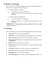
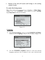
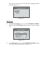
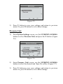
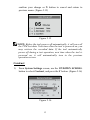
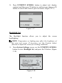
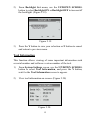
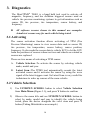
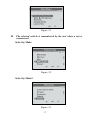
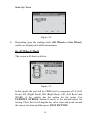
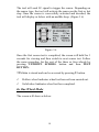
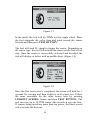
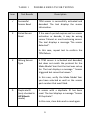
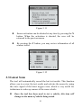
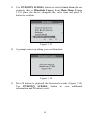
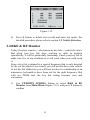
Table of Contents 1. SAFETY PRECAUTIONS AND WARNINGS .............................................. 1 2. TOOL INFORMATION .................................................................................. 2 2.1 TOOL DESCRIPTION ...................................................................................... 2 2.2 SPECIFICATIONS ............................................................................................ 3 2.3 ACCESSORIES INCLUDED............................................................................... 3 2.4 ICONS ............................................................................................................ 4 2.5 KEYBOARD .................................................................................................... 4 2.6 BATTERY CHARGING .................................................................................... 5 2.7 SETTINGS ...................................................................................................... 5 3. DIAGNOSTICS .............................................................................................. 16 3.1 ACTIVATING ................................................................................................ 16 3.2 VEHICLE SELECTION .................................................................................. 16 3.3 LATEST SCAN .............................................................................................. 23 3.4 RKE & RF MONITOR ................................................................................. 25 4. SOFTWARE UPDATE .................................................................................. 27 5. WARRANTY AND SERVICE ...................................................................... 29 5.1 LIMITED ONE YEAR WARRANTY ................................................................ 29 5.2 SERVICE PROCEDURES ................................................................................ 29 1. Safety Precautions and Warnings To prevent personal injury or damage to vehicles and/or the scan tool, read this instruction manual first and observe the following safety precautions at a minimum whenever working on a vehicle: Always perform diagnosis or service in a safe environment. Wear safety eye protection that meets ANSI standards. Keep clothing, hair, hands, tools, test equipment, etc. away from all moving or hot engine parts. Operate the vehicle in a well ventilated work area: Exhaust gases are poisonous. Put blocks in front of the drive wheels and never leave the vehicle unattended while running tests. Use extreme caution when working around the ignition coil, distributor cap, ignition wires and spark plugs. These components create hazardous voltages when the engine is running. Keep a fire extinguisher suitable for gasoline/chemical/ electrical fires nearby. Put the transmission in PARK (for automatic transmission) or NEUTRAL (for manual transmission) and make sure the parking brake is engaged. Refer to the user’s manual for the vehicle being serviced and adhere to all diagnostic procedures and precautions. Otherwise personal injury or unneeded repairs may result. Keep the scan tool dry, clean, free from oil/water or grease. Use a mild detergent on a clean cloth to clean the outside of the scan tool, when necessary. Keep the TPMS tool dry, clean, free from oil, water and grease. Use a mild detergent on a clean cloth to clean the outside of the TPMS tool when necessary. 1 2. Tool Information 2.1 Tool Description 1) ROOBER BOOT – Protects the TPMS tool from drop abrasion, and etc. 2) LCD DISPLAY – Indicates test results. Backlit, 128*64 pixel display with contrast adjustment. 3) UP SCROOL BUTTON – Moves up through menu and submenu items in menu mode. When more than one set of data are retrieved, use this button to move down to next screens for additional data. 2 4) N BUTTON – Cancels a selection (or action) from a menu or return to previous menu. 5) DOWN SCROOL BUTTON – Moves down through menu and submenu items in menu mode. When more than one set of data are retrieved, use this button to move down to next screens for additional data. 6) ? BUTTON – Provides help information. 7) POWER BUTTON – Turns on/off the tool. 8) Y BUTTON – Confirms a selection (or action) from a menu or return to previous menu. 9) TEST BUTTON – Commence a TPM test. 10) USB PORT – Connects the TPMS tool to computer with the USB cable supplied to update the device or for charging. 11) POWER PORT –Connects the TPMS tool to the mains with the charger supplied for battery charging. 2.2 Specifications 1) Display: Backlit, 128*64 pixel display with contrast adjustment 2) Power: 3.7V Li-polymer battery 3) Operating Temperature: 0 to 50°C (32 to 122 °F) 4) Storage Temperature: -20 to 70°C (-4 to 158 °F) 5) Dimensions: Length 195.5 mm (7.7") 6) Width 104 mm (4.09") Height 37.5 mm (1.48") Weight: 0.37kg (0.82lb) 2.3 Accessories Included 1) User’s Manual -- Instructions on tool operations. 3 2) USB cable -- Allows easy update via a PC and an internet connection. 3) Carry case – A nylon case to store the tool when not in use. 4) Magnet (For early model TPM sensors) 5) Charger – Charges or recharges the built-in battery. 6) CD – Includes user’s manual, MaxilinkII Kit, etc. 2.4 Icons 1) “►” -- Indicates current selection. 2) 3) 4) 5) “X/X” -- Indicates total items in a menu and their sequence. “ ” -- Indicates there is data stored in the tool. “ ” -- Indicates battery volume. “ ” -- Indicates USB communication with the computer is established. 6) “? ” -- Indicates there is tip for relevant item. Press ? button to view the details for help or explanation. 7) “…”-- Indicates the item is too long for the display. Press ? button to view the full text. 8) “ ” -- Indicates magnet is required when activating TPMS sensor. 9) “P↓”-- Indicates deflation is required when activating TPM sensor. 10) “ ” -- Indicates test mode One Wheel in the settings of Wheels to Test was selected. 11) “ ” -- Indicates test mode ALL Wheels in the settings of Wheels to Test is selected. 2.5 Keyboard No solvents such as alcohol are allowed to clean the keypad or display. Use a mild nonabrasive detergent and a soft cotton cloth. Do not soak the keypad as the keypad is not waterproof. 4 2.6 Battery Charging The tool has a 3.7v built-in lithium-ion polymer rechargeable battery. There are two means of battery charging: To charge battery by adapter. 1) 2) Locate the power port of the device. Connect the device to the mains with the charger to start charging. To charge battery by USB cable 1) Locate the USB port of the device. 2) Connect the device to computer with the charger to start charging. IMPORTANT: Charge battery in time, otherwise the test results may be incorrect. 2.7 Settings The tool allows you to make the following adjustments and settings. 1) Language: Selects the desired language. 2) ID Format: Sets the ID displaying in Hexadecimal or Decimal. 3) Pressure Unit: Sets the pressure unit in Kpa, Psi or Bar. 4) Temperature Unit: Sets the temperature unit in degree Celsius or Fahrenheit. 5) Beep Set: Turns on/off key-press beep. 6) Wheels to Test: Gives the operator the choice to test One wheel or All wheels. 7) Auto Power-off: Sets the time to power off automatically. 8) Contrast: Adjusts the contrast of the LCD display. 9) Backlight Set: Turn on/off the backlight. 10) Tool Information: Views the important information of the tool. 5 Settings of the unit will remain until change to the existing settings is made. To enter the Setup menu When the scan tool is powered on, it displays a Main Menu. (Figure 2.1) Use UP/DOWN scroll button to select Settings from Main Menu, and press Y button. Figure 2.1 Language 1) From System Settings screen, use the UP/DOWN SCROLL button to select Language, and press the Y button. (Figure 2.2) Figure 2.2 2) Use the UP/DOWN SCROLL button to select the desired language and press the Y button to save your selection and 6 return to previous screen. We provide three language options currently.(Figure 2.3) Figure 2.3 ID Format 1) From System Settings screen, use the UP/DOWN SCROLL button to select ID Format, and press the Y button. (Figure 2.4) Figure 2.4 2) From ID Format screen, use the UP/DOWN SCROLL button to select the desired format of ID. (Figure 2.5) 7 Figure 2.5 3) Press Y button to save your settings and return to previous menu. Or, press N button to exit without change. Pressure Unit 1) From System Settings screen, use the UP/DOWN SCROLL button to select Pressure Unit, and press the Y button. (Figure 2.6) Figure 2.6 2) From Pressure Unit screen, use the UP/DOWN SCROLL button to select the desired unit: Kpa, Psi or Bar. (Figure 2.7) 3) Press Y button to save your settings and return to previous menu. Or, press N button to exit without change. 8 Figure 2.7 Temperature Unit 1) From System Settings screen, use the UP/DOWN SCROLL button to select Temperature Unit, and press the Y button. (Figure 2.8) Figure 2.8 2) From Temperature Unit screen, use the UP/DOWN SCROLL button to select the desired unit of temperature.(Figure 2.9) 3) Press Y button to save your settings and return to previous menu. Or, press N button to exit without change. 9 Figure 2.9 Beep Set This function allows you to turn on/off the build-in speaker for key pressing. 1) From System Settings screen, use the UP/DOWN SCROLL button to select Beep Set, and press the Y button. (Figure 2.10) Figure 2.10 2) From Beep Set menu, use the UP/DOWN SCROLL button to select Beep ON or Beep OFF to turn on/off the beep.(Figure 2.11) 3) Press the Y button to save your selection or N button to cancel and return to previous menu. 10 Figure 2.11 Wheels to Test This function gives you choice to test TPM sensor in ALL Wheels mode or One Wheel mode. 1) From System Settings screen, use the UP/DOWN SCROLL button to select Wheels to Test, and press the Y button. (Figure 2.12) Figure 2.12 2) From Test Unit menu, use the UP/DOWN SCROLL button to select All Wheels or One Wheel to test TPM sensors. (Figure 2.13) 11 Figure 2.13 3) Press the Y button to save your selection or N button to cancel and return to previous menu. NOTE: In All Wheels mode, the tool will determine if a duplicate sensor ID has been read. In this case, the tool will display a message “Sensor ID Duplicate.” In One Wheel mode, the tool will not check the duplicate sensor ID. Auto Power-off 1) From System Settings screen, use the UP/DOWN SCROLL button to select Auto Power-off, and press the Y button. (Figure 2.14) Figure 2.14 2) Press UP/DOWN SCROLL button to increase or decrease the time to auto power-off the tool, and then press Y button to 12 confirm your change or N button to cancel and return to previous menu. (Figure 2.15) Figure 2.15 NOTE: Before the tool powers off automatically, it will save all the TPM test data. Next time when the tool is powered on, you may retrieve the recorded data. If the tool automatically power off during a test operation, next time when the tool is powered on, it will automatically turn to the previous operation screen. Contrast 1) From System Settings screen, use the UP/DOWN SCROLL button to select Contrast, and press the Y button. (Figure 2.16) Figure 2.16 13 2) Press UP/DOWN SCROLL button to adjust tool display contrast, and then press Y button to confirm your change or N button to cancel and return to previous menu. (Figure 2.17) Figure 2.17 Backlight Set The Backlight function allows you to adjust the screen backlighting. NOTE: Temperature or lighting may affect the brightness of the scan tool screen. If necessary, use the Contrast Adjust function to adjust the screen for working conditions. 1) From System Settings screen, use the UP/DOWN SCROLL button to select Backlight Set, and press the Y button. (Figure 2.18) Figure 2.18 14 2) From Backlight Set menu, use the UP/DOWN SCROLL button to select Backlight ON or Backlight OFF to turn on/off the backlight. (Figure 2.19) Figure 2.19 3) Press the Y button to save your selection or N button to cancel and return to previous menu. Tool Information This function allows viewing of some important information such as serial number and software version number of the tool. 1) From System Settings screen, use the UP/DOWN SCROLL button to select Tool Information, and press the Y button; wait for the Tool Information screen to appear. 2) View tool information on screen. (Figure 2.20) Figure 2.20 15 3. Diagnostics The MaxiTPMS® TS401 is a hand held tool used to activate all magnetic, frequency, and tire deflation triggered sensors used on vehicle tire pressure monitoring systems to get information such as sensor ID, tire pressure, tire temperature, sensor battery, and frequency. All software screens shown in this manual are examples. Actual test screens vary for each vehicle being tested. 3.1 Activating The sensor activation function allows activating of TPM (Tire Pressure Monitoring) sensor to view sensor data such as sensor ID, tire pressure, tire temperature, sensor battery, sensor position, frequency. It also sends the sensor data to vehicle ECU to let the ECU learn the positions of sensors whenever tires and wheels are rotated or sensors are replaced. There are two means of activating a TPM sensor: A. Vehicle Selection--To activate the sensor by selecting vehicle make, model and year. B. Latest Scan--The TPMS tool automatically records the latest activated sensor and it activates the sensor by using the wave signal of the latest trigger event. So Latest Scan is very useful for technicians to wake up sensors of the same vehicle. 3.2 Vehicle Selection 1) Use UP/DOWN SCROLL button to select Vehicle Selection from Main Menu (Figure 3.1), and press Y button to confirm. 2) Observe the menu title and use UP/DOWN SCROLL button to select by make, model and year to identify the vehicle being tested, place the device alongside the valve stem and press Y button.(Taking Mitsubishi as an example) 16 Figure 3.1 The selected vehicle is remembered by the tool when a test is commenced. Select by Make Figure 3.2 Select by Model Figure 3.3 17 Select by Year Figure 3.4 3) Depending upon the reading mode (All Wheels or One Wheel), results are displayed in different manners. In All Wheels Mode The screen will show as below. Figure 3.5 In this mode, the tool will do TPMS test in a sequence of LF (Left Front), RF (Right Front), RR (Right Rear), LR (Left Rear) and SPARE, if the vehicle has the option for the spare. Use UP/DOWN SCROLL button to move to the desired wheel for testing. Place the tool alongside the valve stem and point toward the sensor location and then press TEST BUTTON. 18 The tool will send LF signal to trigger the sensor. Depending on the sensor type, the tool will activate the sensor on the first or last step. Once the sensor is successfully activated and decoded, the tool will display as below with an audible beep. (Figure 3.6) Figure 3.6 Once the first sensor test is completed, the screen will hold for 3 seconds for viewing and then switch to next sensor test. Follow the same procedure for the rest of the three or four wheels by pressing UP/DOWN SCROLL button and then TEST BUTTON. TPM data is stored and can be accessed by pressing Y button. Hollow wheel indicates wheel test has not been carried out. Solid wheel indicates wheel test has completed. In One Wheel Mode The screen will show as below. 19 Figure 3.7 In the mode, the tool will do TPMS test for single wheel. Place the tool alongside the valve stem and point toward the sensor location and then press TEST BUTTON. The tool will send LF signal to trigger the sensor. Depending on the sensor type, the tool will activate the sensor on the first or last step. Once the sensor is successfully activated and decoded, the tool will display as below with an audible beep. (Figure 3.8) Figure 3.8 Once the first sensor test is completed, the screen will hold for 3 seconds for viewing and then switch to next sensor test. Follow the same procedure for the other sensor tests by pressing UP/DOWN SCROLL button and then TEST BUTTON. The tool can save up to 10 TPM sensor data records at any one time. If sensors being tested are more than ten pieces, the latest record will overwrite the first one. 20 TABLE 1 Icon POSSIBLE RESULTS FOR TESTING Test Results Description √ Successful Sensor Read TPM sensor is successfully activated and decoded. The tool displays the sensor information. X Failed Sensor Read If the search period expires and no sensor activation or decode, it may be wrong sensor fitment or non-functioning sensor. The tool displays a message “No sensor detected.”. In this case, repeat test to confirm the TPM failure. X Wrong Sensor Type A TPM sensor is activated and decoded, but does not match the protocol for the Make Model Year that the tool was set-up for. The tool displays a message “ Sensor triggered but cannot be known.”. In this case, verify the Make Model Year you have selected as well as the sensor part number that was fitted. D Duplicate ID (only checked in All Wheels mode) A sensor with a duplicate ID has been read. The tool displays a message “Sensor ID Duplicate.”. In this case, clear data and re-read again. 21 NOTE: With Ford Banded sensors, the tool should be held 180 degree away from the stem. Please refer to vehicle user’s manual. If the TPM sensor requires a magnet, place the magnet over the stem and then place the tool alongside the stem, and press TEST BUTTON. Figure 3.9 If the TPM sensor requires tire deflation (of the order of 10PSI), then deflate the tire and place the tool alongside the stem while pressing the TEST BUTTON. Figure 3.10 Anytime while doing the TPMS test, press ? BUTTON to read the sensor make, OEM part no., and relearn information for the vehicle being tested. 22 Figure 3.11 Sensor activation can be aborted at any time by pressing the N button. When the activation is aborted, the user will be returned to the previous menu. By pressing the Y button, you may review information of all sensors tested. Figure 3.12 3.3 Latest Scan The tool will automatically record the last test results. This function allows you to review the test results and activate the sensor by using the wave signal of the latest trigger event, which is very useful for technicians to wake up sensors of the same vehicle. Once the tool has been used to test a vehicle, this item will change to the name of vehicle being tested. 23 1) Use UP/DOWN SCROLL button to select Latest Scan (In our example, this is Mitsubishi Lance) from Main Menu (Figure 3.13), place the device alongside the valve stem and press Y button to confirm. Figure 3.13 2) A prompt comes up asking your confirmation. Figure 3.14 3) Press N button to playback the historical records. (Figure 3.15) Use UP/DOWN SCROLL button to view additional information and N button to exit. 24 Figure 3.15 4) Press Y button to delete test records and enter test mode. For detailed procedure, please refer to section 3.2 Vehicle Selection. 3.4 RKE & RF Monitor Today's keyless remotes -- also known as key fobs -- make life easier. But when your key fob stops working or starts to perform sporadically, it will be particularly frustrating. Check your key fob to make sure it is in top condition so it will work when you really need it. Since a key fob is attuned to a special frequency that is only detected by the car for which it was issued, you will need to have your vehicle to test the fob. Otherwise you will have to take it to a dealership or an automotive locksmith to have them test for the right frequency. But with our TPMS tool, the key fob testing becomes easy and convenient. 1) Use UP/DOWN SCROLL button to select RKE & RF Monitor from Main Menu (Figure 3.16), and press Y button to confirm. 25 Figure 3.16 2) Hold the key fob very close to the tool and press the function buttons on key fob to test. If the button works and key fob is sending a signal, the tool will beep and the screen show as below. If the button does not work, the tool will do nothing. To make sure each button is working properly, please follow the process to test each button in turn. Figure 3.17 3) The progress bar indicates the approximate power level of the key fob. The stronger the signal, the higher the beep tone. The tool only tests 315MHz and 433MHz key fobs. Press N button to return to previous menu. 26 4. Software Update The tool allows user to update software. It works on computers running Windows systems (XP/2000/Vista). To update software, you will need the followings: TS401 CD with update tool PC or laptop with USB ports USB cable CAUTION: DO NOT try to update the tool when battery low. Data will be lost if the device is out of power while updating. 1) Download the latest update files from www.auteltech.com, and save in your computer. our website: 2) Use UP/DOWN SCROLL button to select Update Mode from Main Menu (Figure 4.1), and press Y button to confirm. Figure 4.1 NOTE: When you made a wrong choice and the tool is unable to work properly, you may need to update the programs. To hold N button and power on the scan tool, you will enter the Update Mode forcedly. Then follow the update procedure to refresh the program. 3) Run the Maxi-link II Kit in your computer. (Figure 4.2) 27 Figure 4.2 4) Click Select File button to locate the latest update file you have recently downloaded. 5) Click Update to start updating. 6) Once the update is complete, disconnect the tool from computer, and power it on. The tool is now updated and ready to go. 28 5. Warranty and Service 5.1 Limited One Year Warranty Autel warrants to its customers that this product will be free from all defects in materials and workmanship for a period of one (1) year from the date of the original purchase, subject to the following terms and conditions: 1) The sole responsibility of Autel under the Warranty is limited to either the repair or, at the option of Autel, replacement of the scan tool at no charge with Proof of Purchase. The sales receipt may be used for this purpose. 2) This warranty does not apply to damages caused by improper use, accident, flood, lightning, or if the product was altered or repaired by anyone other than the Manufacturer’s Service Center. 3) Autel shall not be liable for any incidental or consequential damages arising from the use, misuse, or mounting of the scan tool. Some states do not allow limitations on how long an implied warranty lasts, so the above limitations may not apply to you. 4) All information in this manual is based on the latest information available at the time of publication and no warranty can be made for its accuracy or completeness. Autel reserves the right to make changes at any time without notice. 5.2 Service Procedures If you have any questions, please contact your local store, distributor or visit our website at www.auteltech.com. If it becomes necessary to return the tool for repair, contact your local distributor for more information. 29