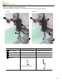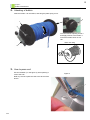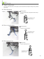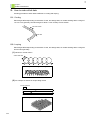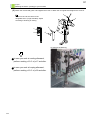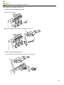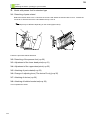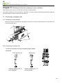
1
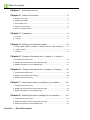
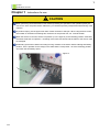
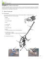
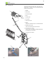
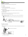
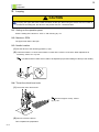
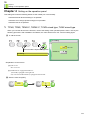
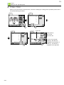
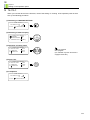
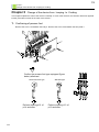
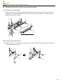
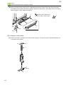
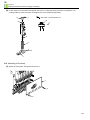
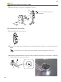
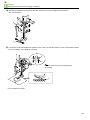
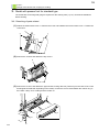
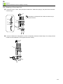
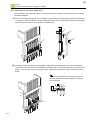
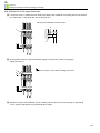
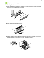
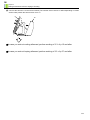
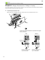
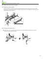
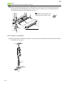
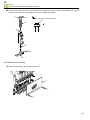
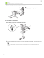
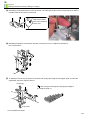
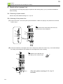
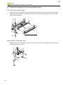
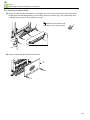
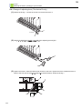
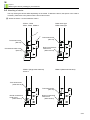
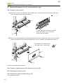
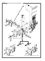
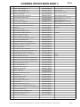
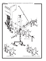
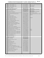
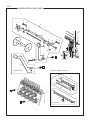
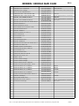
USER’S MANUAL & PARTS LIST KB-2M (L&R) (CORDING & LOOPING) Original Instructions M-KB2M13-E (2013.03) Foreword This manual is a guidebook for the optional device “KB-2M”. Please read this manual thoroughly and operate the device after you understand the contents. This manual may contain discrepancies in detailed specification as compared with the actual production. If you have any question about this manual, consult your TAJIMA distributor. Please keep this manual with care near the machine for quick reference. Tokai Industrial Sewing Machine Co., Ltd. Important safety instructions Items that require your special attention on operation are specified below. ! DANGER Indicates that there is a lot of danger of death or serious injuries[*A] if the instruction is not observed. ! WARNING Indicates that there is a likelihood of death or serious injuries[*A] if the instruction is not observed. ! CAUTION Indicates a potentially hazardous situation which, if not avoided, may result in minor or moderate injury[*B] or property damage. [*A] A condition caused by electric shock, injury, fracture of a bone, etc., that leads to aftereffects, or an injury that necessitates hospitalization or visits to a hospital over a long period. [*B] An injury that does not necessitate hospitalization or visit to a hospital over a long period. : Prohibited items : Items that may cause electric shock if not observed : Items that must be followed carefully to ensure safe operation PT02 Table of contents Chapter 1 Instructions for use Chapter 2 Outline of the device ........................................................2 1. Name of each part ..............................................................................................2 2. Attaching of bobbin .............................................................................................5 3. How to pass cord ................................................................................................5 4. Height of cord presser ........................................................................................6 5. How to make stitch data .....................................................................................7 Chapter 3 Preparation ......................................................................8 1. Cording ...............................................................................................................8 2. Looping ...............................................................................................................9 Chapter 4 Setting on the operation panel ......................................10 1. TFMX, TFMS, TEMX-C, TWMX-C, TCMX mixed type, TLMX mixed type ...... 10 2. TFGN II, TFGS ................................................................................................ 11 3. TEJTII-C ...........................................................................................................12 Chapter 5 Change of the device from Looping to Cording 13 1. Confirming of presser foot ................................................................................13 2. Model with presser foot for noise-reduction type ..............................................14 3. Model with presser foot for standard type ........................................................19 Chapter 6 Change of the device from Cording to Looping ..........25 1. Confirming of presser foot ................................................................................25 2. Model with presser foot for cording .................................................................. 26 3. Model without presser foot ...............................................................................31 Chapter 7 Attaching the device (cording) to your machine ........... 32 1. Confirming of presser foot ................................................................................32 2. Model with presser foot for noise-reduction type ..............................................33 3. Model with presser foot for standard type ........................................................39 Chapter 8 Attaching the device (looping) to your machine ........... 40 1. Confirming of presser foot ................................................................................40 2. Model with presser foot for noise-reduction type ..............................................41 3. Model with presser foot for standard type ........................................................42 Parts list....... End of the manual 1 Chapter 1 Instructions for use Chapter 1 Instructions for use ! CAUTION When performing works described in this manual (excluding the operation of the operation panel), be sure to turn OFF the power switch. Otherwise, you could be injured by unexpected malfunctioning of the machine. To perform looping, set the upper limit value of Max revolution to 600 rpm. When using the device with the number of revolutions exceeding this, the device or the presser foot, etc. could be broken. When the device is not used, set the cord presser (1 in the figure A) to the retracting position. Otherwise, the frame will hit the cord presser 1 according to the frame movement and the frame or the device could be damaged. Embroidery space will be limited according to using condition of the device. Before starting embroidery, perform Trace operation for the design in the state that the cord presser 1 is at the retracting position, and check the embroidery space. Figure A 1 PT02 2 Chapter 2 Outline of the device Chapter 2 Outline of the device The device equipped to left side is described as the device L and the device equipped to right side is described as the device R in this manual. However, even in case of the device R, some picture or illustration of the device L may be used for the explanation in this manual. 1. Name of each part 1-1. The device L Only the main parts are shown here. (Part names are abbreviated.) For details, refer to the separate parts list at the end of this manual. 1 1. Bobbin 2. Plate spring 3. Cord thread guide 2 4. Cord 5. Thread guide 3 6. Cord guide 7. Clutch lever knob 8. Spacer 4 This part is necessary only for 15-needle machine. 9. Cord presser for cording Various sizes are available, for details, please ask the distributor for information. 5 10. Cord presser for looping 7 6 8 9 10 PT02 3 Chapter 2 Outline of the device 1-2. The device R Only the main parts are shown here. (Part names are abbreviated.) For details, refer to the separate parts list at the end of this manual. 1. Bobbin 1 2. Plate spring 3. Cord thread guide 4. Cord 5. Thread guide 2 6. Cord guide 3 7. Clutch lever knob 8. Spacer This part is necessary only for 15-needle machine. 4 9. Adjusting lever B [S] This is an exclusive part for the device R. 10. Cord presser for cording Various sizes are available, for details, please ask the distributor for information. 11. Cord presser for looping 5 7 6 9 8 10 PT02 11 4 Chapter 2 Outline of the device Difference between cording and looping The following indicates the device L. In case of the device R, the direction becomes opposite. Cording Looping 1 1 2 4 2 4 3 3 Cording Looping In the state of being pulled In the state of being pushed Fixed at lower position Fixed at upper position 3 Cord presser For cording For looping 4 Presser foot Noise-reduction type : Use the presser foot for cording. To use 1 Clutch lever knob 2 Spring Standard type: not to use PT02 5 Chapter 2 Outline of the device 2. Attaching of bobbin Insert the bobbin 1 to the shaft 2, and hang the plate spring 3 on 2. 4 1 2 Turn the tension adjusting screw 4 and apply tension to the bobbin 1 so that the bobbin does not run idle. When not using 3 3. How to pass cord Use the threader (1 in the figure A), when passing a cord to the hole. Figure A Refer to p.2 how to pass the cord to the whole of the device. 1 PT02 6 Chapter 2 Outline of the device 4. Height of cord presser The height of the cord presser (1 in the figure A) can be switched to three steps according to using condition of the device. 4-1. When embroidering Stand-by position Figure A This is the position when cording starts. Start cording in this state. Pay attention to the position of a pin. 1 4-2. When not using the device Retracting position Position not to use the device Pay attention to the position of a pin. 4-3. When passing the cord Middle position Position of passing the cord Pay attention to the position of a pin PT02 7 Chapter 2 Outline of the device 5. How to make stitch data Creating procedure of stitch data is different in cording and looping. 5-1. Cording Stitch length differs depending on thickness of cord, and design data, etc. Make stitching within a range of 1.5 to 2.0 mm generally. Set stitch length to about 1.5 mm at sharp curved section. 1.5 to 2.0 mm 1.5 mm 5-2. Looping Stitch length differs depending on thickness of cord, and design data, etc. Make stitching within a range as shown below generally. (1) stitches in circular motion 2.0 to 2.5 mm An example of finishing of sewing (2) An example of stitches in reciprocating motion 2.0 to 2.5 mm An example of finishing of sewing PT02 8 Chapter 3 Preparation Chapter 3 Preparation Prepare before using the machine according to the following procedure. 1. Cording 1-1. Setting on the operation panel Check if setting of the device is YES or ON referring to p.10. 1-2. Maximum RPM Although It is based on the maximum number of revolutions of the machine, set the max revolution according to finishing of sewing. 1-3. Needle location (1) Turn the main shaft counterclockwise to set the main shaft angle to around 180°. (2) Set the device to the retracting position (=>p.6). (3) Lower the needle 1 to check if the needle 1 locates at the center 2 of the hole. When adjustment is necessary, refer to 2-5. of p.17. Lower one after another needle of the heads to be adjusted (to prevent breakage of the tip of the needle). 1 When the needle 1 does not stick in cord during embroidering, move the cord presser 3 to the right a little. 2 1 3 1-4. Height of cord presser (1) Pass a cord to the device. (2) Check if the bottom 1 of the cord presser presses the cord 2 lightly. When adjustment is required, refer to 2-5. of p.17. Use the clutch lever knob 3 (pulled out). 3 1 2 This completes the preparation. PT02 9 Chapter 3 Preparation 2. Looping ! CAUTION In looping, the upper limit value of Max revolution is 600 rpm. When using the device with the number of revolutions exceeding this, the device or the presser foot, etc. could be broken. 2-1. Setting on the operation panel Check if setting of the device is YES or ON referring to p.10. 2-2. Maximum RPM The upper limit value is 600 rpm. 2-3. Needle location (1) Set the device to the retracting position (=>p.6). (2) Lower the needle 1 to check if the needle 1 locates at the center 2 of the hole. When adjustment is necessary, refer to 2-5. of p.29. Lower one after another needle of the heads to be adjusted (to prevent breakage of the tip of the needle). 1 2 2-4. Thrust the clutch lever knob. (1) Thrust the clutch lever knob 1. 1 2 (2) Pass a cord to the device. This completes the preparation. OU11 To adjust the height 2 of loop, refer to (5) of p.30. 10 Chapter 4 Setting on the operation panel Chapter 4 Setting on the operation panel This setting will cause the following status at cord needle (1st or last needle). Automatic/manual thread trimming is not possible. Automatic color change (thread change) is not possible. Automatic start is not possible. 1. TFMX, TFMS, TEMX-C, TWMX-C, TCMX mixed type, TLMX mixed type When you use this device for the first time, check if the setting of the operation panel is set to YES by the following procedure. After installation of software, this value will be set to NO . Perform setting again. (1) To call the screen 3 Cording F3 1 NO[a] YES / NO 2 Press it until the object item appears. Needle No. 9 [b] 3 Cording <Explanation on the screen> [a] YES: to use NO: not to use [b] Needle bar No. equipped with device 1(st needle): equipped to the right side 9 (In case of 9-needle machine): equipped to the left side (2) Select a value and [SET]. [a] [b] YES 9 Example PT03 11 Chapter 4 Setting on the operation panel 2. TFGN II, TFGS When you use this device for the first time, check if the setting (67.Cording) of the operation panel is set to Yes by the following procedure. 1010 7001 1010 7001 A 1C1 TAJIMA_W 14117 st. A 1. Auto Color Change (AC) YES 2.--------------- YES 3.--------------- YES 4.--------------- NO ( Yes, No ) B 1 1 2 3 4 D 1 [1100] h E i 5.--------------- 0 6.--------------- Any 3 YES p q NO YES 7.--------------- 4.0 A 8.--------------- Yes 3J F 9.--------------- --- 10.--------------- 0 h G P1 123 7021 --- j Press twice. P3 P3 i j P2 Select 67. 7064 7021 7064 YES 22.--------------- Any +2 23.--------------- 10mm 24.--------------- 0mm 25.--------------- 0:B 65. +0kg 26.--------------- Any0.8 66. NO 27.--------------- Any0.8 67. Cording 28.--------------- YES 68. 29.--------------- 200mm/sec 69. ( Yes, No ) 61. Network p h P1 i P2 k j P3 P4 l P5 NO ( Yes, No ) YES q NO YES Yes 9 63. m P7 P7 P6 q NO YES p NO 64. nm 1 h P1 i P2 s 9 NO ( Yes, No :1,*****) P6 j P3 NO NO k P4 l P5 s 9 3 m P6 n P7 4 QS03 Cording device YES: to use NO: not to use A A 21. ATH t 1 2 In case of 9 (9-needle machine), the device is equipped to the left side. In case of 1, the device is equipped to the right side. 12 Chapter 4 Setting on the operation panel 3. TEJTII-C When you use this device for the first time, check if the setting D. Cording of the operation panel is set to ON by the following procedure. (1) Switching to MACHINE SETTING ===== EMB START ==== TAJIMA12.TBF 1 0/ 1027 0 1 / 1 5 : 12 3 4 5 6 7 8 9 A B < D > Machine Setting (2) Switching of item to display === FUNCTION MENU == 1. SCREEN ST 2. THREAD SNS 2 3. PRESET HALT [SET] Frame Position (3) Selection of setting value === FUNCTION MENU == B. SATIN ADJ OFF C. BORING OFF D. CORDING OFF Frame Position OFF: not equipped ON: equipped (It is available only when the device is equipped at left side.) (4) Press Set . === FUNCTION MENU == B. SATIN ADJ OFF C. BORING OFF D. CORDING ON Set (5) Completion ===== EMB START ==== TAJIMA12.TBF 1 0/ 1027 0 1 / 1 5 : 12 3 4 5 6 7 8 9 A B < D > PT02 13 Chapter 5 Change of the device from Looping to Cording Chapter 5 Change of the device from Looping to Cording This chapter explains the case of the device L basically. In case of the device R, the direction becomes opposite but the procedure is same as the case of the device L. 1. Confirming of presser foot Remove the screw 1 and detach the body 2. Remove the screw 3 and detach the face plate 4. 4 1 3 2 3 Confirm the presser foot type equipped (figure below) afterward. Noise-reduction type Perform working of 2. of p.14 and after. PT02 Standard type Perform working of 3. of p.19 and after. 14 Chapter 5 Change of the device from Looping to Cording 2. Model with presser foot for noise-reduction type 2-1. Detaching of parts related Remove the screw 1 and detach the upper thread locking device 2 (There may be the case of the lower thread guide 3 for KB-2M depending on model). Loosen the screw 4 and detach the cushion ring 5, the needle clamp 6 and the needle 7. 2 1 5 6 1 3 4 7 2-2. Change of the presser foot (1) Remove the screw 1 and detach the presser foot 2 for noise-reduction type. Attach the presser foot 3 for cording and tighten the screw 1. 1 1 2 3 PT02 15 Chapter 5 Change of the device from Looping to Cording (2) Attach the upper thread locking device 4 and tighten the screw 5 (There may be the case of the lower thread guide 6 for KB-2M depending on model). Attach the cushion ring 7, the needle clamp 8 for cording and the needle 9. Then, tighten the screw 10. 4 Pay attention to the direction (up and down) of the cushion ring 7. 7 5 7 8 5 6 10 9 2-3. Change of cord presser (1) Loosen the screw 1 and detach the collar 2 and the spring 3. Loosen the screw 4 (M3*8) and detach the cord presser 5 for looping. 2 1 3 4 (M3*8) 5 PT02 16 Chapter 5 Change of the device from Looping to Cording (2) Fit the collar 2 into the shaft 6 and tighten the screw 1. Lifting the spring 3 and the cord presser 7 for cording until they touch the step 8, and tighten the screw 9 (M4*8) temporarily. 2 1 Touch the screw 1 to the flat face 10. 10 6 1 8 3 9 (M4*8) 7 2-4. Attaching of the body (1) Attach the face plate1 and tighten the screw 2. 1 2 2 PT02 17 Chapter 5 Change of the device from Looping to Cording (2) Attach the body 3 to the base 4 and tighten the screw 5. 3 The spacer 7 is necessary only for 15needles machine. 7 4 5 6 2-5. Adjustment of cord presser (1) Put the guide pin 1 into the groove. 1 (2) Turn the main shaft counterclockwise to set the main shaft angle to around 180°. Lower the needle bar by hand. Lower one after another needle of the heads to be adjusted (to prevent breakage of the tip of the needle). (3) Regarding crosswise direction, loosen the screw 2 to adjust the position of the cord presser 4 so that the needle locates at the center 3 of the hole. 3 2 PT02 4 18 Chapter 5 Change of the device from Looping to Cording (4) Regarding lengthwise and up/down direction, loosen the screw 5 to adjust the position of the cord presser 4. 5 4 (5) Loosen the screw 6 and adjust the position of the collar 9 so that the bottom 7 of the cord presser presses the cord 8 lightly. Then tighten the screw 6. 9 6 10 Use the clutch lever knob 10 (pulled out) for cording. 7 8 This completes the works. PT02 19 Chapter 5 Change of the device from Looping to Cording 3. Model with presser foot for standard type The needle bar connecting stud gauge is required for the working here (=>p.21). Consult the distributor before working. 3-1. Detaching of parts related (1) Detach the tension base cover 1. Remove the screw 2 and detach the tension base cover 3. Detach the connector 4. 3 2 1 4 (2) Remove the screw 5 and detach the top cover 6. 6 5 (3) Remove the screw 7 and detach the upper thread locking device 8 (There may be the case of the lower thread guide 9 for KB-2M depending on the model). Loosen the screw 10 and detach the cushion ring 11, the needle clamp 12 for cording and the needle 13. 8 7 11 12 7 10 13 PT02 9 20 Chapter 5 Change of the device from Looping to Cording 3-2. Detaching of the presser foot (1) Loosen the screw 1 and 2, then pull up the needle bar 3. Detach the spring 4, the presser foot 5 and the cushion ring 6. 3 Keep the spring 4, the presser foot 5 and the cushion ring 6 as they are not used. 4 1 5 2 6 (2) Lower the needle bar 3 and tighten the screw 1 temporarily. Attach the needle clamp 7 for cording and the needle 8 to the needle bar 3, then tighten the screw 9 firmly. 3 1 7 8 9 PT02 21 Chapter 5 Change of the device from Looping to Cording 3-3. Adjustment of the lower dead point The needle bar connecting stud gauge (1 in the figure below) is required for the working here. For details, consult the distributor. (1) Set the connecting stud gauge 1 to the needle bar except the last needle (Figure below is an example of 1st needle). Loosen the thumbscrew 2 and adjust the size of the connecting stud gauge to make no gap between sections A and B. Then tighten the thumbscrew 2. A 1 2 1 B (2) (1)Set the needle bar connecting stud gauge 1 adjusted at above described (1) to the last needle bar. Loosen the screw 3 and push the needle bar connecting stud 4 to touch the needle bar connecting stud gauge 1, then face the screw 5 to about 30° right. Tighten the screw 3 with no gap between sections A and B. The screw 5 should face to the same direction as the next needle bar and the needle groove should face to the front. 5 3 4 A 1 B PT02 22 Chapter 5 Change of the device from Looping to Cording 3-4. Adjustment of the upper dead point (1) Loosen the screw 1. Rotate the main shaft in the state of the needle bar connecting stud 2 connected to the reciprocator 3, and adjust the main shaft angle to 7°. Viewing the needle bar case from side 2 1 3 (2) At the position where the upper dead point stopper 4 touches the cushion ring 5 lightly, tighten the screw 1. 1 Tighten the screw 1 in the state of facing to the front. 5 4 (3) Afterward, check if the needle bar moves smoothly. When it does not move smoothly or misjumping occurs, perform adjustment of (2) described above again. PT02 23 Chapter 5 Change of the device from Looping to Cording 3-5. Attaching of parts related (1) Attach the upper thread locking device 1 and tighten the screw 2 (There may be the case of the lower thread guide 3 for KB-2M depending on the model). 1 2 3 2 (2) Attach the top cover 4 and tighten the screw 5. 4 5 (3) Slide the needle bar case to the direction of the last needle, and insert the sensor arm 6 into the card bracket 7. Attach the tension base 8 to the bracket 9, then tighten the screw 10. 7 8 10 9 6 10 PT02 24 Chapter 5 Change of the device from Looping to Cording (4) Connect the harness 11 to the tension base 8 (The number of the harness 11 differs depending on model and/or head). Attach the tension base cover 12. 8 11 12 In case you work at cording afterward, perform working of 2-3. of p.15 and after. In case you work at looping afterward, perform working of 2-3. of p.27 and after. PT02 25 Chapter 6 Change of the device from Cording to Looping Chapter 6 Change of the device from Cording to Looping This chapter explains the case of the device L basically. In case of the device R, the direction becomes opposite but the procedure is same as the case of the device L. 1. Confirming of presser foot Remove the screw 1 and detach the body 2. Remove the screw 3 to detach the face cover 4. 4 1 3 2 3 Confirm the existence/absence of presser foot (figure below) afterward. With Without Presser foot (for cord) Perform working of 2. of p.26 and after. PT02 Perform working of 3. of p.31 and after. 26 Chapter 6 Change of the device from Cording to Looping 2. Model with presser foot for cording 2-1. Detaching of parts related Remove the screw 1 and detach the upper thread locking device 2 (There may be the case of the lower thread guide 3 for KB-2M depending on the model). Loosen the screw 4 and detach the cushion ring 5, the needle clamp 6 and the needle 7. 2 1 5 6 1 3 4 7 2-2. Change of the presser foot (1) Remove the screw 1 and detach the presser foot 2 for cording. Attach the presser foot 3 for noisereduction type and tighten the screw 1. 1 1 3 2 PT02 27 Chapter 6 Change of the device from Cording to Looping (2) Attach the upper thread locking device 4 and tighten the screw 5 (There may be the case of the lower thread guide 6 for KB-2M depending on the model). Attach the cushion ring 7, the needle clamp 8 for cording and the needle 9. Then, tighten the screw 10. Pay attention to the direction (up and down) of the cushion ring 7. 4 7 5 7 8 5 6 10 9 2-3. Change of cord presser (1) Loosen the screw 1 and detach the collar 2. Loosen the screw 3 (M4*8) and remove the spring 4 and the cord presser 5 for cording. 2 1 4 3 (M4*8) 5 PT02 28 Chapter 6 Change of the device from Cording to Looping (2) Fit the spring 4 and the collar 2 into the shaft 6 and tighten the screw 1. Lift the cord presser 7 for looping until it touches the step 8, and tighten the screw 9 (M3*8) temporarily. 2 1 Touch the screw 1 to the flat face 10. 10 4 1 6 8 9 (M3*8) 7 2-4. Attaching of the body (1) Attach the face plate1 and tighten the screw 2. 1 2 2 PT02 29 Chapter 6 Change of the device from Cording to Looping (2) Attach the body 3 to the base 4 and tighten the screw 5. 3 7 The spacer 7 is necessary only for 15needles machine. 4 5 6 2-5. Adjustment of cord presser (1) Put the pin 1 in the groove, and thrust the clutch knob 2. 2 1 (2) Turn the main shaft counterclockwise to set the main shaft angle to around 180°. Lower the needle bar by hand. Lower one after another needle of the heads to be adjusted (to prevent breakage of the tip of the needle). PT02 30 Chapter 6 Change of the device from Cording to Looping (3) Regarding crosswise direction, loosen the screw 4 to adjust the position of the cord presser 6 so that the needle locates at the center 5 of the hole. 5 Select the suitable hole to the thickness of the cord. 6 4 (4) Regarding lengthwise and up/down direction, loosen the screw 7 to adjust the position of the cord presser 6. 7 6 (5) To adjust the size of loop 8, loosen the screw 9 and change the height of the stopper guide 10. After the adjustment, thrust the stopper collar 11. Loop large The size of loop 8 will change by changing the height of the stopper guide 10. 10 8 9 11 Loop small This completes the works. PT02 31 Chapter 6 Change of the device from Cording to Looping 3. Model without presser foot The needle bar connecting stud gauge is required for the working here (=>p.21). Consult the distributor before working. 3-1. Detaching of parts related Remove the parts related referring to 3-1. of p.19. 3-2. Attaching of the presser foot (1) Loosen the screw 1 and 2, then pull up the needle bar 3. Attach the spring 4, the presser foot 5 and the cushion ring 6. 3 The presser foot 5 is the same part as the one attached to the next needle bar. 4 1 5 2 6 (2) Lower the needle bar 3 and tighten the screw 4 temporarily. Attach the cushion ring 7, the needle clamp 8 for cording, and needle 9 to the needle bar 3, then tighten the screw 10 firmly. Pay attention to the direction (up and down) of the cushion ring 7. 3 7 4 8 7 10 9 PT02 After that, perform working of 3-3. of p.21 and after. 32 Chapter 7 Attaching the device (cording) to your machine Chapter 7 Attaching the device (cording) to your machine When attaching the device for the first time, follow the procedure below. This chapter explains the case of the device L basically. In case of the device R, the direction becomes opposite but the procedure is same as the case of the device L. 1. Confirming of presser foot 1-1. Detaching of parts related Remove the screw 1 and detach the face plate 2. Remove the screw 3. Remove the screw 4 and detach the thread suspender disk 5. 2 3 1 4 5 1-2. Confirming of presser foot Confirm the presser foot type equipped (figure below) afterward. Noise-reduction type Perform working of 2. of p.33 and after. Standard type Perform working of 3. of p.39 and after. PT02 33 Chapter 7 Attaching the device (cording) to your machine 2. Model with presser foot for noise-reduction type 2-1. Detaching of parts related Remove the screw 1 and detach the upper thread locking device 2 (There may be the case of the lower thread guide 3 depending on the model). Loosen the screw 4 and detach the cushion ring 5, the needle clamp 6 and the needle 7. 2 1 5 6 1 3 4 7 2-2. Change of the presser foot Remove the screw 1 and detach the presser foot 2 for noise-reduction type. Attach the presser foot 3 for cording and tighten the screw 1. 1 3 2 PT02 34 Chapter 7 Attaching the device (cording) to your machine 2-3. Attaching of parts related (1) Attach the upper thread locking device 1 and tighten the screw 2 (There may be the case of the lower thread guide 3 for KB-2M depending on the model). Attach the cushion ring 4, the needle clamp 5 for cording and the needle 6. Then, tighten the screw 7. Pay attention to the direction (up and down) of the cushion ring 4. 1 4 2 4 5 2 3 7 6 (2) Attach the face plate 8 and tighten the screw 9. 8 9 9 PT02 35 Chapter 7 Attaching the device (cording) to your machine 2-4. Change of adjusting lever (The device R only) (1) Detach the E-ring 1. Loosen the screw 2 to remove the screw 3. 3 2 1 (2) Detach the adjusting lever [S] 4 and attach the adjusting lever B [S] 5. 5 4 (3) Tighten the screw 7 while the ratchet mark 6 faces to the front. Tighten the screw 8 while the screw 8 faces to the front (on the same line against the ratchet mark 6). Attach the E-ring 1. 7 8 6 PT02 1 36 Chapter 7 Attaching the device (cording) to your machine 2-5. Attaching of device The way of fixing the device differs depending on the model. To attach the device, the spacer or the collar is necessary. Refer also to the parts list at the end of this manual. (1) Attach the device 1 to the needle bar case 2. TFGN II, TFGS TLMX mixed type TFMX, TFMS, TWMX-C TCMX mixed type 2 1 Truss head screw (M4×10) Truss head screw (M4×10) Round countersunk head screw (9/64×40×9.5) Countersunk head screw (M4×10) TEMX-C (Single head machine) TEMX-C (Multi head machine) TEJTII-C Truss head screw (9/64×40×10) Truss head screw (M4×10) Round countersunk head screw (9/64×40×9.5) Round countersunk head screw (9/64×40×9.5) QS03 37 Chapter 7 Attaching the device (cording) to your machine (2) Attach the cord thread guide 3 and tighten the screw 4. Attach the cord guide 5 and tighten the screw 6. 3 Fix the screw 6 at the center of the elongated hole 7 (rough standard). Adjust according to finishing of sewing. 4 5 7 2 6 An example of attaching In case you work at cording afterward, perform working of 2-5. of p.17 and after. In case you work at looping afterward, perform working of 2-5. of p.29 and after. PT02 38 Chapter 7 Attaching the device (cording) to your machine 2-6. Attaching of bobbin bracket set In case of rotary-type tension base (1) Remove the screw 1. 1 (2) Attach the bobbin bracket set 2 and tighten the screw 3. 2 3 In case of normal tension base Fix the bobbin bracket set 2 with the tension stud 1 (two spots). 2 1 1 PT02 39 Chapter 7 Attaching the device (cording) to your machine 3. Model with presser foot for standard type 3-1. Detaching of parts related Detach the tension base cover 1. Remove the screw 2 and detach the tension base cover 3. Detach the connector 4. Remove the screw 5 and detach the top cover 6. The shape may be different depending on the model (figure below). 3 2 6 4 1 5 Follow the procedure below afterward. 3-2. Detaching of the presser foot(=>p.20) 3-3. Adjustment of the lower dead point(=>p.21) 3-4. Adjustment of the upper dead point(=>p.22) 3-5. Attaching of parts related(=>p.23) 3-6. Change of adjusting lever (The device R only)(=>p.35) 3-7. Attaching of device(=>p.36) 3-8. Attaching of bobbin bracket set(=>p.38) This completes the works. PT02 40 Chapter 8 Attaching the device (looping) to your machine Chapter 8 Attaching the device (looping) to your machine When attaching the device for the first time, follow the procedure below. This chapter explains the case of the device L basically. In case of the device R, the direction becomes opposite but the procedure is same as the case of the device L. 1. Confirming of presser foot 1-1. Detaching of parts related Remove the screw 1 and detach the face plate 2. Remove the screw 3. Remove the screw 4 and detach the thread suspender disk 5. 2 3 1 4 5 1-2. Confirming of presser foot Confirm the presser foot type equipped (figure below) afterward. Noise-reduction type Perform working of 2. of p.41 and after. Standard type Perform working of 3. of p.42 and after. PT02 41 Chapter 8 Attaching the device (looping) to your machine 2. Model with presser foot for noise-reduction type 2-1. Change of parts related (1) Remove the screw 1 and detach the lower thread guide 2. Loosen the screw 3 and detach the cushion ring 4, the needle clamp 5 and the needle 6. 1 2 4 5 1 In case of this type, loosen the screw 3 to detach the cushion ring 4, the needle clamp 5 and the needle 6. 3 6 (2) Attach the lower thread guide 7 for KB-2M and tighten the screw 1. Attach the cushion ring 4, the needle clamp 8 for cording and the needle 6 and tighten the screw 3. Attach the 9 and tighten the screw 10. Pay attention to the direction (up and down) of the cushion ring 4. 1 7 4 8 9 8 10 3 6 10 Follow the procedure below afterward. 2-2. Change of adjusting lever (The device R only)(=>p.35) 2-3. Attaching of device(=>p.36) 2-4. Attaching of bobbin bracket set(=>p.38) This completes the works. PT02 4 42 Chapter 8 Attaching the device (looping) to your machine 3. Model with presser foot for standard type 3-1. Change of parts related(=>p.41) 3-2. Change of adjusting lever (The device R only)(=>p.35) 3-3. Attaching of device(=>p.36) 3-4. Attaching of bobbin bracket set(=>p.38) This completes the works. PT02 CONTENTS ● CORDING DEVICE MAIN BODY L……………………………………………………………EK- 1L ● CORDING DEVICE MAIN BODY R……………………………………………………………EK- 1R ● BOBBIN/NEEDLE BAR CASE…………………………………………………………………EK- 2 *Regarding the part number that contains description of @, the part differs depending on model, spec. etc. *When you place an order of such a part, please also inform us of your model, embroidery space and manufacturing number of the machine. Ex. TEJTⅡ-C1501 [Model] (360 x 500)S [Emb. Space] No.01234 [Mfg. No.] (PT03) EK-1L CORDING DEVICE MAIN BODY L 32 17 18 31 38 16 33 40 34 24 30 34 25 26 27 4 39 29 28 2 18 7 6 10 11 3 9 35 37 13 1 5 36 12 19 8 14 15 [TEMX-C(Single), TEJTII-C] 20 4 21 22 23 4 2 3 2 3 5 8 [TLMX/TCMX Mix] 5 8 [TFGN/GS/MX/MS Series, TEMX-C(Multi), TWMX-C] (PT03) EK-1L CORDING DEVICE MAIN BODY L Part Name No. 1 1 1 2 3 3 4 4 5 5 6 7 8 8 9 10 11 12 13 14 15 16 17 18 19 20 21 22 23 24 25 26 27 28 29 30 31 32 33 34 35 36 37 37 38 38 39 40 41 42 BASE :CORD PRESSER :47 :L BASE :CORD PRESSER :45 :L BASE :CORD PRESSER :50B :L SPACER :4.2MM DIA. TRUSS HEAD SCREW :9/64*40*10 TRUSS HEAD SCREW :M4*10 SPACER :3.8MM DIA. COLLAR :NO.1 :4.2MM DIA. ROUND COUNTERSUNK HEAD SCREW :9/64*40*9.5 COUNTERSUNK HEAD SCREW :M4*10 SPACER GUIDE PIPE :CORD :L TRUSS HEAD SCREW :9/64*6 TRUSS HEAD SCREW :9/64*40*10 GUIDE :CORD PILOT ROD :L GUIDE :CORD PILOT ROD :R FLAT FILLISTER HEAD SCREW :1/8*44*5 THREAD SUSPENDER DISK COMPRESSION SPRING :0.3MM DIA. PRESSER :THREAD SUSPENDER SPRING STEPPED SCREW :NO.1 :9/64*9 ROD :CORD GUIDE STOPPER COLLAR :7.24MM DIA. HEXAGON SOCKET HEAD SET SCREW :M3*3 COMPRESSION SPRING :0.5MM DIA. CORD PRESSER :NO.1:L :1.1-2.5MM DIA. CORD PRESSER :NO.2 :L[S] HEXAGON SOCKET HEAD CAP SCREW :M4*8 HEXAGON SOCKET HEAD CAP SCREW :M3*8 HEXAGON SOCKET HEAD CAP SCREW :M4*5 PLAIN WASHER :M4*10*T0.8 BALL PLUNGER :BST4 HEXAGON NUT TYPE 1 :M4 KNOB :CLUTCH LEVER SHAFT :STOPPER SCREW WITH PIN :NO.5 :1/8-2.5 O-RING :S-5 THREAD GUIDE :CORD THREAD GUIDE :NO.2 TRUSS HEAD SCREW :9/64*6 CORD GUIDE :L TRUSS HEAD SCREW :9/64*4 NEEDLE CLAMP :CORDING DEVICE :L[S] NEEDLE CLAMP :CORDING DEVICE :15-NEEDLE :L[S] GUIDE :STOPPER :L[S] STOPPER GUIDE :15-NEEDLE :L[S] SCREW WITH PIN :NO.4 :M3-6 GUIDE PIPE :CORD :L[A] Part No. 0L113024L000 0L113012L010 0L113037L010 0L1130320000 SA30741001CL S130041001SD 0L1130310010 502542010010 SA53740951CL S150041002SD 0L1130180000 0L113029L000 SA30740601CL SA30741001CL 0L1130340000 0L1130350000 SA41730501CN 0B0200050000 507603020010 0B0200060000 512153060000 0L1130360020 502101020010 S170030301TN 507605140010 0L113038@010 0L113028LS20 S120040802TN S120030802TN S120040502TN S301041002SC 615400020000 S210040001SC 080310170000 0L1130200000 513550010000 612200100000 0L1130300010 516202020000 SA30740601CL 0L113001L010 SA30740401CL 0L113033LS10 0L113015LS20 0L113019LS00 0L113021LS00 0L1130390000 0L113029LA00 Remark TFGN/TFGS/TFMX/TFMS Series, TEMX-C(Multi), TWMX-C TLMX/TCMX MIX TEMX-C(Single), TEJTII-C TEMX-C(Single), TEJTII-C TFGN/TFGS/TFMX/TFMS Series, TLMX/TCMX MIX, TEMX-C(Multi), TWMX-C TEMX-C(Single), TEJTII-C TFGN/TFGS/TFMX/TFMS Series, TLMX/TCMX MIX, TEMX-C(Multi), TWMX-C TLMX/TCMX MIX, TEMX-C, TEJTII-C TFGN/TFGS/TFMX/TFMS Series, TWMX-C 15-Needle 15-Needle Cording Looping Note: As for parts with mark @, please follow our instructions on Table of Contents in your parts order. (PT03) EK-1R CORDING DEVICE MAIN BODY R (EXCLUDING TEJTII-C) 32 17 18 31 38 16 33 40 4 34 39 28 29 34 25 30 26 27 2 24 18 7 6 10 11 3 37 9 15 14 13 12 8 19 21 4 35 1 5 36 [TEMX-C(Single)] 20 23 22 4 2 3 2 3 8 [TLMX/TCMX Mix] 5 8 5 [TFGN/GS/MX/MS Series, TEMX-C(Multi), TWMX-C] (PT03) CORDING DEVICE MAIN BODY R (EXCLUDING TEJTII-C) Part Name No. 1 1 1 2 3 3 4 4 5 5 6 7 8 8 9 10 11 12 13 14 15 16 17 18 19 20 21 22 23 24 25 26 27 28 29 30 31 32 33 34 35 36 37 37 38 38 39 40 41 42 BASE :CORD PRESSER :47 :R BASE :CORD PRESSER :45 :R BASE :CORD PRESSER :50B :R SPACER :4.2MM DIA. TRUSS HEAD SCREW :9/64*40*10 TRUSS HEAD SCREW :M4*10 SPACER :3.8MM DIA. COLLAR :NO.1 :4.2MM DIA. ROUND COUNTERSUNK HEAD SCREW :9/64*40*9.5 COUNTERSUNK HEAD SCREW :M4*10 SPACER GUIDE PIPE :CORD :R TRUSS HEAD SCREW :9/64*6 TRUSS HEAD SCREW :9/64*40*10 GUIDE :CORD PILOT ROD :L GUIDE :CORD PILOT ROD :R FLAT FILLISTER HEAD SCREW :1/8*44*5 THREAD SUSPENDER DISK COMPRESSION SPRING :0.3MM DIA. PRESSER :THREAD SUSPENDER SPRING STEPPED SCREW :NO.1 :9/64*9 ROD :CORD GUIDE STOPPER COLLAR :7.24MM DIA. HEXAGON SOCKET HEAD SET SCREW :M3*3 COMPRESSION SPRING :0.5MM DIA. CORD PRESSER :NO.1 :R :1.1-2.5MM DIA.[S] CORD PRESSER :NO.2 :R[S] HEXAGON SOCKET HEAD CAP SCREW :M4*8 HEXAGON SOCKET HEAD CAP SCREW :M3*8 HEXAGON SOCKET HEAD CAP SCREW :M4*5 PLAIN WASHER :M4*10*T0.8 BALL PLUNGER :BST4 HEXAGON NUT TYPE 1 :M4 KNOB :CLUTCH LEVER SHAFT :STOPPER SCREW WITH PIN :NO.5 :1/8-2.5 O-RING :S-5 THREAD GUIDE :CORD THREAD GUIDE :NO.2 TRUSS HEAD SCREW :9/64*6 CORD GUIDE :R TRUSS HEAD SCREW :9/64*4 NEEDLE CLAMP :CORDING DEVICE :R[S] NEEDLE CLAMP :CORDING DEVICE :15-NEEDLE :R[S] GUIDE :STOPPER :R[S] STOPPER GUIDE :15-NEEDLE :R[S] SCREW WITH PIN :NO.4 :M3-6 GUIDE PIPE :CORD :R[A] Part No. 0L113024R000 0L113012R010 0L113037R010 0L1130320000 SA30741001CL S130041001SD 0L1130310010 502542010010 SA53740951CL S150041002SD 0L1130180000 0L113029R000 SA30740601CL SA30741001CL 0L1130340000 0L1130350000 SA41730501CN 0B0200050000 507603020010 0B0200060000 512153060000 0L1130360020 502101020010 S170030301TN 507605140010 0L113041@S00 0L113028RS20 S120040802TN S120030802TN S120040502TN S301041002SC 615400020000 S210040001SC 080310170000 0L1130200000 513550010000 612200100000 0L1130300010 516202020000 SA30740601CL 0L113001R010 SA30740401CL 0L113033RS10 0L113015RS20 0L113019RS00 0L113021RS00 0L1130390000 0L113029RA00 EK-1R Remark TFGN/TFGS/TFMX/TFMS Series, TEMX-C(Multi), TWMX-C TLMX/TCMX MIX TEMX-C(Single) TEMX-C(Single) TFGN/TFGS/TFMX/TFMS Series, TLMX/TCMX MIX, TEMX-C(Multi), TWMX-C TEMX-C(Single) TFGN/TFGS/TFMX/TFMS Series, TLMX/TCMX MIX, TEMX-C(Multi), TWMX-C TLMX/TCMX MIX, TEMX-C TFGN/TFGS/TFMX/TFMS Series, TWMX-C 15-Needle 15-Needle Cording Looping Note: As for parts with mark @, please follow our instructions on Table of Contents in your parts order. (PT03) EK-2 BOBBIN/NEEDLE BAR CASE 11 15 12 3 10 14 8 13 23 21 22 25 9 24 18 16 20 19 2 4 5 1 A 6 7 35 17 4 B Right-side spec. TEJTII-C, TEMX-C (Single) 27 26 31 34 30 28 A 29 32 B 15-Needle 33 (PT03) EK-2 BOBBIN / NEEDLE BAR CASE Part Name No. 1 1 2 3 3 4 4 5 6 7 8 9 10 11 12 13 14 15 16 17 18 19 20 21 22 23 24 25 26 27 28 29 30 30 30 30 31 32 33 34 35 36 37 38 39 40 41 42 43 44 PRESSER FOOT :CORDING[A] PRESSER FOOT :CORD[A] SPLIT COLLAR :PRESSER FOOT BOBBIN BRACKET L-SIDE :ROTARY :KB2 BOBBIN BRACKET R-SIDE :ROTARY :KB2 BRACKET :NO.2 :BOBBIN HOLDER :L BRACKET :NO.2 :BOBBIN HOLDER :R HEXAGON SOCKET HEAD CAP SCREW :M4*25 SPRING WASHER :M4 PLAIN WASHER :M4*10*T0.8 BASE :BOBBIN SHAFT HOLDER :LARGE PAN HEAD SCREW :M3*10 BRACKET :BOBBIN :L STEPPED SCREW :NO.1 :M4*11.4 WAVE WASHER :M6 PLATE SPRING :T0.5 PLATE SPRING PAN HEAD SCREW :M3*3 BRACKET :BOBBIN :R HEXAGON SOCKET HEAD CAP SCREW :M4*10 WASHER WITH TEETH :M4 KNOBBED SCREW :K-UN2006 M4*8 COMPRESSION SPRING :0.7MM DIA. PLATE SPRING :T0.3 PAN HEAD SCREW :M2*3 SCREW WITH PIN :NO.5 :M4-104 HEXAGON NUT TYPE 1 :M4 BOBBIN :LARGE LOWER THREAD GUIDE[A] LOWER THREAD GUIDE[S] THREAD GUIDE COLLAR :1.8MM DIA. ROUND FILLISTER HEAD SCREW :11/64*6 TENSION SPRING :NO.2 :0.6MM DIA. TENSION SPRING :NO.2 :0.6MM DIA. TENSION SPRING :NO.2 :0.6MM DIA. TENSION SPRING :NO.2 :0.6MM DIA. ROUND FILLISTER HEAD SCREW :9/64*40*12 PRESSER :SPRING[S] TRUSS HEAD SCREW :M3*3 HEXAGON NUT TYPE 3 :9/64*6*2 ADJUSTING LEVER :B[S] Part No. 0L1130080A00 0L1130230A00 090460040030 ULA1L0000100 ULA1R0000100 0L113014L000 0L113014R000 S120042501TN S402040001KC S301041002SC 0L1310060000 S160031002SD 08068010L000 512104030000 S305061051TN 507805010030 507803110010 S160030301MZ 08068010R000 S120041002TN S304040851TP S181040801SD 507607140010 507803040030 S160020301MZ 513504020010 S210040002SD 0L1310070000 0L043142@A00 0L043142@S00 516503010010 SA43750601CN 507506040020 507506010020 507506020020 507506030030 SA43741201CN 090220050S00 S130030301SD SB12740601MZ 09021014BS00 Remark TLMX/TCMX MIX TFGN/TFMX/TFMS Series, TEMX-C, TWMX-C, TEJTII-C L-side spec. R-side spec. TFGN/TFMX/TFMS Series, TLMX/TCMX MIX, TEMX-C, TWMX-C L-side spec. R-side spec. TFGN/TFMX/TFMS Series, TLMX/TCMX MIX, TEMX-C, TWMX-C 6-Needle 9-Needle 12-Needle 15-Needle 15-Needle R-side spec. TFGN/TFMX/TFMS Series, TLMX/TCMX MIX, TEMX-C, TWMX-C Note: As for parts with mark @, please follow our instructions on Table of Contents in your parts order. (PT03) 1st Edition 13th Edition April, 1999 March, 2013 Manufactured by: Tokai Industrial Sewing Machine Co., Ltd. NO.1800, Ushiyama-cho, Kasugai, Aichi-pref., 486-0901, Japan Telephone:568-33-1161 Fax:568-33-1191 Distributed by: Tajima Industries Ltd. 19-22, Shirakabe, 3-chome, Higashi-ku, Nagoya, 461-0011, Japan Telephone:52-932-3444 Fax:52-932-2457 Copy, reprint, or reform of a part or whole of this manual without permission is prohibited.