1
M
S D A M A E S E , I TI NE T
R M YN T D S M A S A YN ES O , I A E & R ~ Y SY D R M
M ~ D W MO S, TIC SY T & TE NC C D S & D S ~ IDW AM EM YN ~ D ID MO , IN TIC E T ME NC TIC SY DY S ~ MI NA ST YN S ~ I
A Y E
D M E A
Y Y Y
T .
D R .
S N
O S A Y W M C D S &
M IN
N TIC NE ST E C. DY STE YN S ~ ~ M NA STE NA DY ES M , IN MA NE ES ET . ~ YN YS DY ER ~ M DY TE AM DY WE OM MS MA DY
C
N
. ~ DY S & D TER ~ M NA MS AM DY ID MO M MA NE T & ET C. TIC S T & ER M AM TEM NA S ~ ID AM MS AT NE ST ET , IN TIC
M
Y
S
E
Y
W
W
S M NA S YN S ID O , I AT N E M , I TIC SY D R ~ M D S D S IDW O S MA D E O , I IC SY & ER C
~ ID M TE A ~ W M NC IC E S ET N
ST YN S ~ ID YN TE YN ~ D E ME , IN TI YN ST M NC DY ST DY S . ~
D
C
S
T
D
E
E
D
M
W
E
C
M
M
S
E
A
O
A M
AM Y
ES M S, AT YN ST TE . ~ DY YS & D RS . ~ YN EM M DY WE M S, AM YN T TE C. D E S & D TE . ~ NA EM NA ~ D
N
M
A
& R ~ Y
M
O
T
M
A
S, ATI E S T & ETE INC IC E S & D RS ID NA EM YN ~ MID M S, TIC NE ST M INC ATI E S D S M NA YS YN RS ID MO S, I AT YN
I
IN C D YS D R . DY YS Y ~ D W MO S A DY W OM NC D S & ET . C D YS YN ~ D ID M TE AM ~ D W ME NC IC
ET C. YN TE YN S ~ ~ M NA TE NA Y ES M , IN MA NE ES ET . ~ YN YS DY ER ~ M YN TE AM YN WE OM MS A Y ES TE . ~ D
ER ~ M A MS AM DY ID MO M MA NE T & ET C. TIC S T & ER M AM TE NA S ~ ID A MS AT E ST ET , IN TIC NE T & R M
YN S ID MO ,
AT NE WE M S, I TIC SY DY ER ~ M D YST D S IDW O MS MA D WE MO , IN IC SY & ER C. D SY DY S ~ ID
I
Y
S
N
Y ~
M ,
D S D S ~ Y S N D
S E N
T Y S M
S
A ~ W M
I
M MA DY ES ET C. C D SY T & TE C. DY TE NA ~ D IDW NA EM NA DY ES ET INC IC NE T & ET C. YN TE YN ~ M NA TE AM Y
~
T
R ~ N
M
M S M
S, T N T E ~
I M
M
D
M YN STE DY S M AM MS AT YN ES O , IN AT NE & ER . ~ YN SY DY ER M AM S AM DY DW O MS AT
R
I
E
I
&
C
N
TE C
A N E M ,
S ID A M N ~ ID
S N S ID O ,
,
I
I E T M
S
I S D S M
R . ~ DY YS DY ~ D W MO S AM DY W OM INC C D SY & ET C. ~ C D YS YN ~ D IDW AM TE AM ~ D WE ME INC TIC E S ST ET INC
O M
YN S ~ M NA T NA Y ES M , IN A NE ES E . ~ Y S DY ER M Y TE AM Y
AT YN ST TE . ~ DY YS & ER .
S
E
M
T
N
E
N
N
T
N
E
T
T
M
N
T
S ID A M A E S E , I IC E & R M N T D S
AM D ID MO M A E & T C. IC S
T T N
E Y ~
& ER M AM E A
S T
, I AT YN WE M S, I TIC SY D ER ~ M D YS D S IDW O MS MA ~ D WE MO , I IC SY & ER C. D SY DY S ~ IDW AM MS NA
E S E N
Y S
Y T Y ~
N
M ,
O
T Y S M N D S D
S Y S
ET C. IC D SY T TE C. DY TE NA ~ IDW NA EM NA DY ES ET INC IC NE T ET C. YN TE YN S ~ ~ M NA TE NA DY ES M , IN MA
N
&
&
D
T
ER ~ M Y ST D RS ~ M NA M MA Y E MO S, MA NE T & ER . ~ DY S D ER ~ M A MS AM DY ID MO M MA E & ET C.
M
S
E
Y
S
N
W
N S
I
M S ~ IDW AM EM YN ~ D ID MO , IN TIC E T ME NC TIC SY DY S ~ MI NA ST YN S ~ IDW OM , IN AT NE E ME , IN TIC SY DY RS ~
A
T .
C IC S ST T C D S N ~
O S A Y W M C D S &
D S N D D M E A
IN TIC DY ES M , IN MA NE ES ET . ~ YN YS DY ER ~ M YN TE AM YN WE OM MS MA DY ES ETE . ~ D YS & ER . ~ YN TEM AM D
C D NE T ET C TI S T E M A TE N S ID A M A E S E , TI NE T
R M YN T D S M A S A
R . ~ YN S & D ER . ~ C D YS & D RS ID MO MS AM ~ D W MO S, TIC SY T & TE INC C D S & D S ~ ID AM EM YN ~ D ID MO , IN TI
S M A Y Y S M Y T Y ~ W M , A Y E
W O S A Y W M C
Y YS Y
S M IN D S D R .
T
S
M ~ D IDW MO TE NA ~ IDW NA EM NA DY ES ET INC IC NE T ET C. YN TE YN S ~ ~ M NA TE NA DYN ES M , IN MA NE ES ET . ~
AT Y E M M M DY E M S M N T E . D S &
ER ~ M A MS AM DY ID MO M MA E T & ET C. TIC S T & ER
,
N
D
A
&
O
R
~
Y
A
E
E
Y
S
S
I
S
N
I
IN C E T T , TI E T M N TI S D S M N S YN S ID MO ,
AT NE WE M S, I TIC SY DY ER ~ M D YST D S
I
C
A
C
T
Y
C DY SY & ER IN C
N
E
Y
~
I
. ~ N S D S C D SY & D TE . ~ D YS N D DW MO EM AM ~ D WE ME C IC S ST ETE NC D ST NA S ~ ID NA EM YNA
A
.
S M A T YN ~ . ~ YN ST Y R M YN TE M YN E M S AT YN ST TE ~ DY YS & R . ~ YN EM M D WE M S
~ ID M EM A D M A E N S ID A M A E S E , I I
R M N T D S M A S A YN S O , I
E
AM DY W OM S M YN ID MO MS AM ~ D W MO S, TIC SY T & TE NC C D S & D S ~ IDW AM EM YN ~ D ID MO , IN TIC E T ME N
&
,
E
A
Y
W
AT NE ES ET IN TIC E S WE ME , IN ATI YN ST ME INC DY ST DY RS . ~ YN ST YN D E OM S, I AM YN E ME C. DY SYS D TE
Y
T
C
C E
S
C IC S
Y R
A
E
S
N A E S
.
~
E N ~ M A
.~
YS & D RS . ~ DY YST T & TER C. ~ DY S & D TE ~ M NA M AM D ID MO EM MA NE T & ET C. TIC S T & TER M NA TE NA
D
S MI YN TE YN ~ MI NA EM D S M NA YS YN RS ID MO S, I AT YN WE M S, I TIC SY D ER ~ M D YS D S IDW MO MS M
Y S
Y T Y ~
M ,
~ DW A M A DY DW M S YN ~ ID M TE A ~ W M NC IC E S ET N
C DY ST NA ~ ID NA EM NA D ES E IN
SY T
D
D
E
D
M
W
E
M
S
,
M
M
O
E
O
N
A
.
AT YN ES O , I AT E ES M IN M YN E M S AT YN ST TE ~ DY S & R . ~ N EM M DY WE M S M YN T TE C
IC E T ME NC IC SY T & ET C. AT E ST ET , IN IC E & RS MI NA TE DY S ~ MI AM S, AT N ST OM , IN AT E & D RS
C D SY & D TE . ~ D ST D ER ~ M IC SY & ER C. DY SY DY ~ DW M MS NA D DW O IN IC E S & ET C. IC SY YN
M C D Y D
. Y S Y R M Y
D S D S ~
S N D E O , M Y
~ D S
E Y S
ER ~ M NA TE NA S ID NA M NA ~ IDW YN TE YN ~ M NA TE AM YN ST ME IN AT NE EST ET . ~ YN ST YN ER M YN TE A
S IDW MO MS MA ~ D WE MO S, I MA DY ES AM MS AM DY IDW MO MS AT E & TE C. ~ IC SY & ER MI AM EM AM S ~ IDW AM MS
D
S
YN ~
ES ME , IN TIC YN ST ME NC TIC NE T & OM , IN ATI NE ES ME , IN IC YS DY RS M DY ST DY S ~ W OM S, AT DY ES OM , I
D
A Y T T C
E & T .~
S
E C C S T T C D T N ~ ID N E N D E E IN I N T E
, I MA NE & ER . ~ DY SY D ER M DY YS DY TE . ~ DY YS & ER . ~ YN EM AM DY WE AM MS AM YN ST TE C. C D E S & T
N TI S D S M N S YN S ID NA TE NA R M N T D S M A S AT N S O , I A E & R ~ Y Y D
C C
A T
Y
E Y
N T
M
N
S
TE . ~ D YS YN ~ D IDW MO EM AM ~ D WE MO MS MA S ~ IDW AM MS NA ~ D IDW O , IN IC E S T & ME C. IC SY DY ~ MID AM ST N
E
A
T
T
M C D
Y
Y
Y
O
D S N D
T
A Y S
N RS MID NA EM MA NE ES ME S, I TI NE T ME , IN IC DYN ES M , IN MA NE ES ET . ~ YN YST DY ER ~ M YN TE AM YN WE OM MS
AM ~ W M S T
& T C D E T ET C TI S T E M A E N S ID A M A E S E
T T N C
&
T T
. C Y & R
Y
M M A ~
D
O , IC S & E C D S D E .
M S T
Dyn-Loc IV
USER MANUAL
revised July 2001
www.dynesystems.com
Phone: 1-800-657-0726
DyneSystems,QF
Contact Information
Shipping Address:
W209 N17391 Industrial Drive
Jackson, WI 53037
Mailing Address:
P.O. Box 18
Jackson, WI 53037
Toll Free Phone:
(800)657-0726
Fax:
(262)677-9308
Web:
www.dynesystems.com
No part of this manual may be reproduced or transmitted in any form or by any
means, including photocopying, recording, or using information storage and
retrieval systems, for any purpose other than the purchaser's own use, without the
express written permission of Dyne Systems Co., LLC.
©
2001 by Dyne Systems Co., LLC. All Rights Reserved.
Any other product names and services identified in this manual are trademarks or
registered trademarks of their respective owners. No such uses, or the use of any
trade name, is intended to convey endorsement or other affiliation with Dyne
Systems Co., LLC.
Revision History
Item #: MAN-DL4-00001
May, 2001
Initial Version
Contents
Chapter 1 – Introduction
Audience . . . . . . . . . . . . . . . . . . . . . . . . . . . . . . . . . . . . . . . . . . . . . . . . . . . . . . . . . . . . . . . .
Features . . . . . . . . . . . . . . . . . . . . . . . . . . . . . . . . . . . . . . . . . . . . . . . . . . . . . . . . . . . . . . . . .
Location Requirements . . . . . . . . . . . . . . . . . . . . . . . . . . . . . . . . . . . . . . . . . . . . . . . . . . . . .
Safety . . . . . . . . . . . . . . . . . . . . . . . . . . . . . . . . . . . . . . . . . . . . . . . . . . . . . . . . . . . . . . . . . . .
Electrocution Hazard . . . . . . . . . . . . . . . . . . . . . . . . . . . . . . . . . . . . . . . . . . . . . . . . . . .
Electrostatic Discharge Damage . . . . . . . . . . . . . . . . . . . . . . . . . . . . . . . . . . . . . . . . . . .
Safety Signs and Symbols. . . . . . . . . . . . . . . . . . . . . . . . . . . . . . . . . . . . . . . . . . . . . . . .
System Safety Labels. . . . . . . . . . . . . . . . . . . . . . . . . . . . . . . . . . . . . . . . . . . . . . . .
Documentation Conventions . . . . . . . . . . . . . . . . . . . . . . . . . . . . . . . . . . . . . . . . . .
1-1
1-2
1-3
1-3
1-4
1-4
1-4
1-4
1-5
Chapter 2 – Specifications
Location . . . . . . . . . . . . . . . . . . . . . . . . . . . . . . . . . . . . . . . . . . . . . . . . . . . . . . . . . . . . .
Unit Specifications . . . . . . . . . . . . . . . . . . . . . . . . . . . . . . . . . . . . . . . . . . . . . . . . . . . . .
Mechanical. . . . . . . . . . . . . . . . . . . . . . . . . . . . . . . . . . . . . . . . . . . . . . . . . . . . . . . .
Power Supply Requirements . . . . . . . . . . . . . . . . . . . . . . . . . . . . . . . . . . . . . . . . . .
RPM Transducer Requirement . . . . . . . . . . . . . . . . . . . . . . . . . . . . . . . . . . . . . . . .
Load Feedback/Transducer Requirements. . . . . . . . . . . . . . . . . . . . . . . . . . . . . . . .
Connections . . . . . . . . . . . . . . . . . . . . . . . . . . . . . . . . . . . . . . . . . . . . . . . . . . . . . . .
Control Modes . . . . . . . . . . . . . . . . . . . . . . . . . . . . . . . . . . . . . . . . . . . . . . . . . . . . .
Control Origin . . . . . . . . . . . . . . . . . . . . . . . . . . . . . . . . . . . . . . . . . . . . . . . . . . . . .
Reference Setpoint Entry. . . . . . . . . . . . . . . . . . . . . . . . . . . . . . . . . . . . . . . . . . . . .
LAC Entry (Rate of Change Setpoint) . . . . . . . . . . . . . . . . . . . . . . . . . . . . . . . . . .
Control Regulation and Drift . . . . . . . . . . . . . . . . . . . . . . . . . . . . . . . . . . . . . . . . . .
Instrumentation Features . . . . . . . . . . . . . . . . . . . . . . . . . . . . . . . . . . . . . . . . . . . . .
Eddy-Current Power Amplifier . . . . . . . . . . . . . . . . . . . . . . . . . . . . . . . . . . . . . . . .
Overspeed/Underspeed Safety. . . . . . . . . . . . . . . . . . . . . . . . . . . . . . . . . . . . . . . . .
Data Acquisition . . . . . . . . . . . . . . . . . . . . . . . . . . . . . . . . . . . . . . . . . . . . . . . . . . .
Computer Control . . . . . . . . . . . . . . . . . . . . . . . . . . . . . . . . . . . . . . . . . . . . . . . . . .
Remote Control Unit . . . . . . . . . . . . . . . . . . . . . . . . . . . . . . . . . . . . . . . . . . . . . . . .
DC or AC Four Quadrant Motoring Controls . . . . . . . . . . . . . . . . . . . . . . . . . . . . .
Throttle Controller Option. . . . . . . . . . . . . . . . . . . . . . . . . . . . . . . . . . . . . . . . . . . .
MAN-DL4-00001
2-1
2-1
2-1
2-1
2-1
2-1
2-2
2-2
2-2
2-2
2-2
2-2
2-2
2-3
2-3
2-3
2-3
2-4
2-4
2-4
i
Chapter 3 – Installation
Before You Begin. . . . . . . . . . . . . . . . . . . . . . . . . . . . . . . . . . . . . . . . . . . . . . . . . . . . . . . . . .
Signal Wiring Requirements . . . . . . . . . . . . . . . . . . . . . . . . . . . . . . . . . . . . . . . . . . . . . . . . .
MS Connectors General Information . . . . . . . . . . . . . . . . . . . . . . . . . . . . . . . . . . . . . . .
Load Cell Feedback MS Connector . . . . . . . . . . . . . . . . . . . . . . . . . . . . . . . . . . . . .
RPM Feedback MS Connector . . . . . . . . . . . . . . . . . . . . . . . . . . . . . . . . . . . . . . . .
Sub-D type Connector Wiring and Part Numbers. . . . . . . . . . . . . . . . . . . . . . . . . . . . . .
General . . . . . . . . . . . . . . . . . . . . . . . . . . . . . . . . . . . . . . . . . . . . . . . . . . . . . . . . . . .
Barrier Strip Connections . . . . . . . . . . . . . . . . . . . . . . . . . . . . . . . . . . . . . . . . . . . . . . . . . . . .
Power Wiring General Information. . . . . . . . . . . . . . . . . . . . . . . . . . . . . . . . . . . . . . . . .
GND . . . . . . . . . . . . . . . . . . . . . . . . . . . . . . . . . . . . . . . . . . . . . . . . . . . . . . . . . . . . .
L1-L2 . . . . . . . . . . . . . . . . . . . . . . . . . . . . . . . . . . . . . . . . . . . . . . . . . . . . . . . . . . . .
L3-L4 . . . . . . . . . . . . . . . . . . . . . . . . . . . . . . . . . . . . . . . . . . . . . . . . . . . . . . . . . . . .
F1-F2 . . . . . . . . . . . . . . . . . . . . . . . . . . . . . . . . . . . . . . . . . . . . . . . . . . . . . . . . . . . .
OS/US . . . . . . . . . . . . . . . . . . . . . . . . . . . . . . . . . . . . . . . . . . . . . . . . . . . . . . . . . . .
Notes on the Remote Control Unit . . . . . . . . . . . . . . . . . . . . . . . . . . . . . . . . . . . . . . . . . . . . .
Wiring the Remote Unit . . . . . . . . . . . . . . . . . . . . . . . . . . . . . . . . . . . . . . . . . . . . . . . . .
3-1
3-1
3-2
3-2
3-2
3-2
3-2
3-3
3-4
3-4
3-4
3-4
3-5
3-5
3-5
3-5
Chapter 4 – Display Set-Up and Maintenance
Before You Begin. . . . . . . . . . . . . . . . . . . . . . . . . . . . . . . . . . . . . . . . . . . . . . . . . . . . . . . . . .
Overview . . . . . . . . . . . . . . . . . . . . . . . . . . . . . . . . . . . . . . . . . . . . . . . . . . . . . . . . . . . . . . . .
Speed Display Decimal Place. . . . . . . . . . . . . . . . . . . . . . . . . . . . . . . . . . . . . . . . . . . . . . . . .
Speed Display Averaging . . . . . . . . . . . . . . . . . . . . . . . . . . . . . . . . . . . . . . . . . . . . . . . . . . . .
Torque Display Decimal Place . . . . . . . . . . . . . . . . . . . . . . . . . . . . . . . . . . . . . . . . . . . . . . . .
Displaying Un-Averaged Data . . . . . . . . . . . . . . . . . . . . . . . . . . . . . . . . . . . . . . . . . . . . . . . .
Zeroing the Torque Display . . . . . . . . . . . . . . . . . . . . . . . . . . . . . . . . . . . . . . . . . . . . . . . . . .
Spanning the Torque Display . . . . . . . . . . . . . . . . . . . . . . . . . . . . . . . . . . . . . . . . . . . . . . . . .
Using the Shunt Cal Button . . . . . . . . . . . . . . . . . . . . . . . . . . . . . . . . . . . . . . . . . . . . . . . . . .
Power Display Setup . . . . . . . . . . . . . . . . . . . . . . . . . . . . . . . . . . . . . . . . . . . . . . . . . . . . . . .
Setting System Defaults . . . . . . . . . . . . . . . . . . . . . . . . . . . . . . . . . . . . . . . . . . . . . . . . . . . . .
Push Button Functions . . . . . . . . . . . . . . . . . . . . . . . . . . . . . . . . . . . . . . . . . . . . . . . . . . . . . .
4-1
4-1
4-2
4-2
4-3
4-3
4-3
4-4
4-5
4-5
4-6
4-6
Chapter 5 – Dynamometer Startup Procedure
Wiring and Conduit Checks . . . . . . . . . . . . . . . . . . . . . . . . . . . . . . . . . . . . . . . . . . . . . . . . . .
Load Cell Checks . . . . . . . . . . . . . . . . . . . . . . . . . . . . . . . . . . . . . . . . . . . . . . . . . . . . . . . . . .
Checking Load Cell Mechanics . . . . . . . . . . . . . . . . . . . . . . . . . . . . . . . . . . . . . . . . . . .
Setting the Current Limit . . . . . . . . . . . . . . . . . . . . . . . . . . . . . . . . . . . . . . . . . . . . . . . . . . . .
Setting the Emergency Stop Level . . . . . . . . . . . . . . . . . . . . . . . . . . . . . . . . . . . . . . . . . . . . .
Checking Magnetic Pickup. . . . . . . . . . . . . . . . . . . . . . . . . . . . . . . . . . . . . . . . . . . . . . . . . . .
Stability Adjustments . . . . . . . . . . . . . . . . . . . . . . . . . . . . . . . . . . . . . . . . . . . . . . . . . . . . . . .
Performance Checks. . . . . . . . . . . . . . . . . . . . . . . . . . . . . . . . . . . . . . . . . . . . . . . . . . . . . . . .
Overspeed Trip Setting. . . . . . . . . . . . . . . . . . . . . . . . . . . . . . . . . . . . . . . . . . . . . . . . . . . . . .
Other Control System DIP Switch, Jumper, and Adjustment Options. . . . . . . . . . . . . . . . . .
DS255 DIP Switch A . . . . . . . . . . . . . . . . . . . . . . . . . . . . . . . . . . . . . . . . . . . . . . . . . . .
DS105C Jumpers and DIP Switches . . . . . . . . . . . . . . . . . . . . . . . . . . . . . . . . . . . . . . . .
DS105C Analog Torque and Speed Output Adjustments . . . . . . . . . . . . . . . . . . . . . . . . . . .
ii
5-1
5-2
5-2
5-3
5-3
5-4
5-4
5-5
5-6
5-6
5-6
5-6
5-7
MAN-DL4-00001
Analog RPM . . . . . . . . . . . . . . . . . . . . . . . . . . . . . . . . . . . . . . . . . . . . . . . . . . . . . . . . . . 5-7
Analog Torque . . . . . . . . . . . . . . . . . . . . . . . . . . . . . . . . . . . . . . . . . . . . . . . . . . . . . . . . 5-7
DS500 Series Control System Boards (Replacing DS250) . . . . . . . . . . . . . . . . . . . . . . . . . . 5-8
DS500 Power Supply PCB . . . . . . . . . . . . . . . . . . . . . . . . . . . . . . . . . . . . . . . . . . . . . . . 5-8
DS501/502 Reference Generator and Control PCBs . . . . . . . . . . . . . . . . . . . . . . . . . . . 5-8
Enabling a 1/10th LAC Mode. . . . . . . . . . . . . . . . . . . . . . . . . . . . . . . . . . . . . . . . . . . . . 5-9
Setting up Speed Signal Input Source. . . . . . . . . . . . . . . . . . . . . . . . . . . . . . . . . . . . . . . 5-9
Adjusting the Fault Braking on Non-Motoring Dynamometers . . . . . . . . . . . . . . . . . . . 5-9
Method One . . . . . . . . . . . . . . . . . . . . . . . . . . . . . . . . . . . . . . . . . . . . . . . . . . . . . . . 5-9
Method Two. . . . . . . . . . . . . . . . . . . . . . . . . . . . . . . . . . . . . . . . . . . . . . . . . . . . . . 5-10
Method Three . . . . . . . . . . . . . . . . . . . . . . . . . . . . . . . . . . . . . . . . . . . . . . . . . . . . 5-10
Enhanced Torque Circuit . . . . . . . . . . . . . . . . . . . . . . . . . . . . . . . . . . . . . . . . . . . . . . . 5-11
Using Motoring Torque Mode . . . . . . . . . . . . . . . . . . . . . . . . . . . . . . . . . . . . . . . . . . . 5-11
Master Mode . . . . . . . . . . . . . . . . . . . . . . . . . . . . . . . . . . . . . . . . . . . . . . . . . . . . . 5-11
Computer Mode . . . . . . . . . . . . . . . . . . . . . . . . . . . . . . . . . . . . . . . . . . . . . . . . . . . 5-11
Instant Loading of a New Setpoint . . . . . . . . . . . . . . . . . . . . . . . . . . . . . . . . . . . . . . . . 5-11
Number of Counts DIP Switches . . . . . . . . . . . . . . . . . . . . . . . . . . . . . . . . . . . . . . . . . 5-11
Enhanced DV/DT Circuit . . . . . . . . . . . . . . . . . . . . . . . . . . . . . . . . . . . . . . . . . . . . . . . 5-11
DS501 Dip Switch Settings . . . . . . . . . . . . . . . . . . . . . . . . . . . . . . . . . . . . . . . . . . . . . 5-12
DS501 Jumper Settings. . . . . . . . . . . . . . . . . . . . . . . . . . . . . . . . . . . . . . . . . . . . . . . . . 5-13
DIP Switches and Jumpers on the DS503 CPU Board . . . . . . . . . . . . . . . . . . . . . . . . . 5-16
DS503 Jumper Settings. . . . . . . . . . . . . . . . . . . . . . . . . . . . . . . . . . . . . . . . . . . . . . . . . 5-17
Jumper setting descriptions . . . . . . . . . . . . . . . . . . . . . . . . . . . . . . . . . . . . . . . . . . 5-17
Speed Display DP Options on the DS503 . . . . . . . . . . . . . . . . . . . . . . . . . . . . . . . 5-17
Summary of DS503 CPU Board Jumper Settings . . . . . . . . . . . . . . . . . . . . . . . . . 5-18
LED Indicators on the DS503 CPU Board . . . . . . . . . . . . . . . . . . . . . . . . . . . . . . . . . . 5-18
LED1 . . . . . . . . . . . . . . . . . . . . . . . . . . . . . . . . . . . . . . . . . . . . . . . . . . . . . . . . . . . 5-18
LED2 . . . . . . . . . . . . . . . . . . . . . . . . . . . . . . . . . . . . . . . . . . . . . . . . . . . . . . . . . . . 5-18
Chapter 6 – Operating Instructions
Eddy-Current Dynamometer Operation. . . . . . . . . . . . . . . . . . . . . . . . . . . . . . . . . . . . . . . . .
Preliminary . . . . . . . . . . . . . . . . . . . . . . . . . . . . . . . . . . . . . . . . . . . . . . . . . . . . . . . . . . .
Eddy-Current Dynamometer Start-Up . . . . . . . . . . . . . . . . . . . . . . . . . . . . . . . . . . . . . . . . . .
Systems with Zero Speed Protection Enabled Start-Up . . . . . . . . . . . . . . . . . . . . . . . . .
Systems with Zero Speed Protection Disabled Start-Up . . . . . . . . . . . . . . . . . . . . . . . .
Setting the LAC (Rate of Change Setpoint). . . . . . . . . . . . . . . . . . . . . . . . . . . . . . . . . . . . . .
Entering Setpoints . . . . . . . . . . . . . . . . . . . . . . . . . . . . . . . . . . . . . . . . . . . . . . . . . . . . . . . . .
Mode Changes and Transients . . . . . . . . . . . . . . . . . . . . . . . . . . . . . . . . . . . . . . . . . . . . . . . .
Forced Engine Stop Using the Dynamometer . . . . . . . . . . . . . . . . . . . . . . . . . . . . . . . . . . . .
RPM Mode . . . . . . . . . . . . . . . . . . . . . . . . . . . . . . . . . . . . . . . . . . . . . . . . . . . . . . . . . . .
Torque Mode. . . . . . . . . . . . . . . . . . . . . . . . . . . . . . . . . . . . . . . . . . . . . . . . . . . . . . . . . .
Emergency Stop . . . . . . . . . . . . . . . . . . . . . . . . . . . . . . . . . . . . . . . . . . . . . . . . . . . . . . . . . . .
Transferring to Computer Control Mode . . . . . . . . . . . . . . . . . . . . . . . . . . . . . . . . . . . . . . . .
Motoring Dynamometer Operation . . . . . . . . . . . . . . . . . . . . . . . . . . . . . . . . . . . . . . . . . . . .
Remote Operator’s Station . . . . . . . . . . . . . . . . . . . . . . . . . . . . . . . . . . . . . . . . . . . . . . . . . . .
Using the Remote Unit . . . . . . . . . . . . . . . . . . . . . . . . . . . . . . . . . . . . . . . . . . . . . . . . . .
MAN-DL4-00001
6-1
6-1
6-2
6-2
6-2
6-3
6-4
6-4
6-4
6-4
6-5
6-5
6-5
6-5
6-6
6-6
iii
Chapter 7 – Computer Interfacing
Serial Port Hardware Format . . . . . . . . . . . . . . . . . . . . . . . . . . . . . . . . . . . . . . . . . . . . . . . . . 7-1
Data Format (Baud). . . . . . . . . . . . . . . . . . . . . . . . . . . . . . . . . . . . . . . . . . . . . . . . . . . . . 7-1
Clear to Send (CTS) Input to the Dyn-Loc . . . . . . . . . . . . . . . . . . . . . . . . . . . . . . . . . . . 7-1
Request to Send (RTS) Output . . . . . . . . . . . . . . . . . . . . . . . . . . . . . . . . . . . . . . . . . . . . 7-2
RS232 Signals . . . . . . . . . . . . . . . . . . . . . . . . . . . . . . . . . . . . . . . . . . . . . . . . . . . . . . . . . 7-2
Serial Port Software Format . . . . . . . . . . . . . . . . . . . . . . . . . . . . . . . . . . . . . . . . . . . . . . . . . . 7-2
Serial Port ASCII Commands . . . . . . . . . . . . . . . . . . . . . . . . . . . . . . . . . . . . . . . . . . . . . . . . 7-2
Why Choose ASCII. . . . . . . . . . . . . . . . . . . . . . . . . . . . . . . . . . . . . . . . . . . . . . . . . . . . . 7-2
Keywords Command Line . . . . . . . . . . . . . . . . . . . . . . . . . . . . . . . . . . . . . . . . . . . . . . . 7-3
Control Codes . . . . . . . . . . . . . . . . . . . . . . . . . . . . . . . . . . . . . . . . . . . . . . . . . . . . . . . . . 7-3
The Prompt (\) Character. . . . . . . . . . . . . . . . . . . . . . . . . . . . . . . . . . . . . . . . . . . . . . . . . 7-4
Hardware Handshaking Option . . . . . . . . . . . . . . . . . . . . . . . . . . . . . . . . . . . . . . . . . . . . 7-4
Standard Notation for Command Reference . . . . . . . . . . . . . . . . . . . . . . . . . . . . . . . . . . 7-4
Repeat Command . . . . . . . . . . . . . . . . . . . . . . . . . . . . . . . . . . . . . . . . . . . . . . . . . . . . . . 7-5
Querying the Firmware Version . . . . . . . . . . . . . . . . . . . . . . . . . . . . . . . . . . . . . . . . . . . 7-7
Configuration Commands . . . . . . . . . . . . . . . . . . . . . . . . . . . . . . . . . . . . . . . . . . . . . . . . 7-7
Setting a Non-Standard Display Units Code . . . . . . . . . . . . . . . . . . . . . . . . . . . . . . 7-7
Setting Error Que Mode. . . . . . . . . . . . . . . . . . . . . . . . . . . . . . . . . . . . . . . . . . . . . . 7-7
System Restart . . . . . . . . . . . . . . . . . . . . . . . . . . . . . . . . . . . . . . . . . . . . . . . . . . . . . 7-8
Forcing E-Squared Write . . . . . . . . . . . . . . . . . . . . . . . . . . . . . . . . . . . . . . . . . . . . . 7-8
Resetting the Crash Counter . . . . . . . . . . . . . . . . . . . . . . . . . . . . . . . . . . . . . . . . . . 7-8
Data Acquisition Commands . . . . . . . . . . . . . . . . . . . . . . . . . . . . . . . . . . . . . . . . . . . . . 7-8
Acquiring 200hz Data . . . . . . . . . . . . . . . . . . . . . . . . . . . . . . . . . . . . . . . . . . . . . . . 7-8
Acquiring 10hz Data . . . . . . . . . . . . . . . . . . . . . . . . . . . . . . . . . . . . . . . . . . . . . . . . 7-8
Acquiring 50hz Data . . . . . . . . . . . . . . . . . . . . . . . . . . . . . . . . . . . . . . . . . . . . . . . . 7-9
Acquiring Averaged (Displayed) Data. . . . . . . . . . . . . . . . . . . . . . . . . . . . . . . . . . . 7-9
Acquiring All Averaged Data in a Single Block . . . . . . . . . . . . . . . . . . . . . . . . . . . 7-9
Acquiring Dyn-Loc Status Bits . . . . . . . . . . . . . . . . . . . . . . . . . . . . . . . . . . . . . . . . 7-9
Reading the Lever Wheel switches . . . . . . . . . . . . . . . . . . . . . . . . . . . . . . . . . . . . 7-10
Control Commands . . . . . . . . . . . . . . . . . . . . . . . . . . . . . . . . . . . . . . . . . . . . . . . . . . . . 7-10
Selecting Operating Modes . . . . . . . . . . . . . . . . . . . . . . . . . . . . . . . . . . . . . . . . . . 7-10
Setting the LAC . . . . . . . . . . . . . . . . . . . . . . . . . . . . . . . . . . . . . . . . . . . . . . . . . . . 7-11
Changing the Operating Setpoint. . . . . . . . . . . . . . . . . . . . . . . . . . . . . . . . . . . . . . 7-11
Calibration Commands . . . . . . . . . . . . . . . . . . . . . . . . . . . . . . . . . . . . . . . . . . . . . . . . . 7-11
Zeroing the Torque Display . . . . . . . . . . . . . . . . . . . . . . . . . . . . . . . . . . . . . . . . . . 7-11
Spanning the Torque Display . . . . . . . . . . . . . . . . . . . . . . . . . . . . . . . . . . . . . . . . . 7-11
Activating SHUNT CAL . . . . . . . . . . . . . . . . . . . . . . . . . . . . . . . . . . . . . . . . . . . . 7-12
DTC-1 Commands . . . . . . . . . . . . . . . . . . . . . . . . . . . . . . . . . . . . . . . . . . . . . . . . . . . . 7-12
Automatically Formatted DTC-1 Commands . . . . . . . . . . . . . . . . . . . . . . . . . . . . 7-12
Sending any DTC-1 Command, No Wait for Answer . . . . . . . . . . . . . . . . . . . . . . 7-12
Sending any DTC-1 Command, Wait for Answer . . . . . . . . . . . . . . . . . . . . . . . . . 7-12
Querying the DTC-1 Firmware Version. . . . . . . . . . . . . . . . . . . . . . . . . . . . . . . . . 7-12
DTC-1 'Type Through' Mode. . . . . . . . . . . . . . . . . . . . . . . . . . . . . . . . . . . . . . . . . 7-13
RoadLoad Commands . . . . . . . . . . . . . . . . . . . . . . . . . . . . . . . . . . . . . . . . . . . . . . . . . . 7-13
Setting ROM Defaults . . . . . . . . . . . . . . . . . . . . . . . . . . . . . . . . . . . . . . . . . . . . . . 7-13
Control Word . . . . . . . . . . . . . . . . . . . . . . . . . . . . . . . . . . . . . . . . . . . . . . . . . . . . . 7-13
'CutOff' Velocity (KPH) . . . . . . . . . . . . . . . . . . . . . . . . . . . . . . . . . . . . . . . . . . . . . 7-14
Setting 'Constants' . . . . . . . . . . . . . . . . . . . . . . . . . . . . . . . . . . . . . . . . . . . . . . . . . 7-14
Querying and Resetting the Derivative . . . . . . . . . . . . . . . . . . . . . . . . . . . . . . . . . 7-14
Derivative Averaging Period . . . . . . . . . . . . . . . . . . . . . . . . . . . . . . . . . . . . . . . . . 7-14
iv
MAN-DL4-00001
Derivative Multiplier . . . . . . . . . . . . . . . . . . . . . . . . . . . . . . . . . . . . . . . . . . . . . . .
Gravitational Constant . . . . . . . . . . . . . . . . . . . . . . . . . . . . . . . . . . . . . . . . . . . . . .
Force Calculation. . . . . . . . . . . . . . . . . . . . . . . . . . . . . . . . . . . . . . . . . . . . . . . . . .
Setpoint Limit . . . . . . . . . . . . . . . . . . . . . . . . . . . . . . . . . . . . . . . . . . . . . . . . . . . .
Starting and Stopping RoadLoad. . . . . . . . . . . . . . . . . . . . . . . . . . . . . . . . . . . . . .
CoastDown Option . . . . . . . . . . . . . . . . . . . . . . . . . . . . . . . . . . . . . . . . . . . . . . . .
RoadLoad Command Summary . . . . . . . . . . . . . . . . . . . . . . . . . . . . . . . . . . . . . .
Troubleshooting Commands . . . . . . . . . . . . . . . . . . . . . . . . . . . . . . . . . . . . . . . . . . . . .
Comments (', single quote) . . . . . . . . . . . . . . . . . . . . . . . . . . . . . . . . . . . . . . . . . .
Querying d2a Settings . . . . . . . . . . . . . . . . . . . . . . . . . . . . . . . . . . . . . . . . . . . . . .
Port I/O . . . . . . . . . . . . . . . . . . . . . . . . . . . . . . . . . . . . . . . . . . . . . . . . . . . . . . . . .
Free Memory . . . . . . . . . . . . . . . . . . . . . . . . . . . . . . . . . . . . . . . . . . . . . . . . . . . . .
Simulating Power Cycling. . . . . . . . . . . . . . . . . . . . . . . . . . . . . . . . . . . . . . . . . . .
System CRASH Detection. . . . . . . . . . . . . . . . . . . . . . . . . . . . . . . . . . . . . . . . . . .
Dyn-Loc RS232 Command Summary Table . . . . . . . . . . . . . . . . . . . . . . . . . . . . . . . .
Error Message Format . . . . . . . . . . . . . . . . . . . . . . . . . . . . . . . . . . . . . . . . . . . . . . . . .
Dyn-Loc 4/186 RS232 System Error Messages by Number . . . . . . . . . . . . . . . . . . . .
New Dyn-Loc 4/186 Operating System Features . . . . . . . . . . . . . . . . . . . . . . . . . . . . .
Serial Port BINARY Commands . . . . . . . . . . . . . . . . . . . . . . . . . . . . . . . . . . . . . . . . . . . . .
Why use BINARY? . . . . . . . . . . . . . . . . . . . . . . . . . . . . . . . . . . . . . . . . . . . . . . . . . . .
The BINARY Handshake . . . . . . . . . . . . . . . . . . . . . . . . . . . . . . . . . . . . . . . . . . . . . . .
BINARY Data Acquisition Commands . . . . . . . . . . . . . . . . . . . . . . . . . . . . . . . . . . . .
Return data block for EQ 1 setup if error waiting in que. . . . . . . . . . . . . . . . . . . .
D.P. Placement Byte . . . . . . . . . . . . . . . . . . . . . . . . . . . . . . . . . . . . . . . . . . . . . . .
Data Dump WITHOUT DTC-1 Status Word . . . . . . . . . . . . . . . . . . . . . . . . . . . .
Short Form Data Dump with DTC-1 Status Word . . . . . . . . . . . . . . . . . . . . . . . .
Short Form Data Dump (Spd/Tq Only) . . . . . . . . . . . . . . . . . . . . . . . . . . . . . . . . .
Get RoadLoad DEBUG Information . . . . . . . . . . . . . . . . . . . . . . . . . . . . . . . . . . .
PAL-Based Frequency Measurement DEBUG Dump. . . . . . . . . . . . . . . . . . . . . .
BINARY Control Commands . . . . . . . . . . . . . . . . . . . . . . . . . . . . . . . . . . . . . . . . . . . .
Dyn-Loc MODE control . . . . . . . . . . . . . . . . . . . . . . . . . . . . . . . . . . . . . . . . . . . .
DTC-1 MODE Control . . . . . . . . . . . . . . . . . . . . . . . . . . . . . . . . . . . . . . . . . . . . .
Dyn-Loc LAC Control. . . . . . . . . . . . . . . . . . . . . . . . . . . . . . . . . . . . . . . . . . . . . .
Dyn-Loc SETPOINT Control . . . . . . . . . . . . . . . . . . . . . . . . . . . . . . . . . . . . . . . .
DTC-1 LAC Control . . . . . . . . . . . . . . . . . . . . . . . . . . . . . . . . . . . . . . . . . . . . . . .
DTC-1 SETPOINT Control. . . . . . . . . . . . . . . . . . . . . . . . . . . . . . . . . . . . . . . . . .
BINARY Command Summary Table . . . . . . . . . . . . . . . . . . . . . . . . . . . . . . . . . . . . . .
Parallel Computer Control . . . . . . . . . . . . . . . . . . . . . . . . . . . . . . . . . . . . . . . . . . . . . . . . . .
Bypassing the Serial Port for SP/MD/LAC . . . . . . . . . . . . . . . . . . . . . . . . . . . . . . . . .
Parallel Control Port Characteristics. . . . . . . . . . . . . . . . . . . . . . . . . . . . . . . . . . . . . . .
Parallel Control Port: Setting the LAC . . . . . . . . . . . . . . . . . . . . . . . . . . . . . . . . . . . . .
LAC Data Entry Procedure . . . . . . . . . . . . . . . . . . . . . . . . . . . . . . . . . . . . . . . . . .
Parallel Control Port: Entering Setpoints . . . . . . . . . . . . . . . . . . . . . . . . . . . . . . . . . . .
Setpoint Entry Procedure. . . . . . . . . . . . . . . . . . . . . . . . . . . . . . . . . . . . . . . . . . . .
Parallel Control Port: Changing the MODE . . . . . . . . . . . . . . . . . . . . . . . . . . . . . . . . .
Changing from RPM to Torque Control Mode . . . . . . . . . . . . . . . . . . . . . . . . . . .
Changing from Torque to RPM Control Mode . . . . . . . . . . . . . . . . . . . . . . . . . . .
Causing a Dyne Off Condition . . . . . . . . . . . . . . . . . . . . . . . . . . . . . . . . . . . . . . .
Causing an Emergency Stop Condition . . . . . . . . . . . . . . . . . . . . . . . . . . . . . . . . .
Parallel Control Port: Acquiring Status Bits. . . . . . . . . . . . . . . . . . . . . . . . . . . . . . . . .
Parallel Data Acquisition Port Characteristics. . . . . . . . . . . . . . . . . . . . . . . . . . . . . . . . . . .
MAN-DL4-00001
7-15
7-15
7-15
7-15
7-15
7-15
7-17
7-17
7-18
7-18
7-18
7-18
7-18
7-18
7-19
7-20
7-21
7-24
7-25
7-25
7-25
7-25
7-25
7-25
7-27
7-28
7-28
7-29
7-29
7-31
7-32
7-32
7-33
7-33
7-34
7-34
7-35
7-35
7-35
7-36
7-36
7-37
7-37
7-37
7-37
7-38
7-38
7-39
7-39
7-40
7-41
v
Parallel Data Acquisition Port Operation . . . . . . . . . . . . . . . . . . . . . . . . . . . . . . . . . . . 7-41
Using the Remote OCS Connector for Additional Parallel Control Capabilities . . . . . 7-42
Chapter 8 – Connector Pin-Out Listings
Barrier Strip . . . . . . . . . . . . . . . . . . . . . . . . . . . . . . . . . . . . . . . . . . . . . . . . . . . . . . . . . . . . . .
Load Feedback MS. . . . . . . . . . . . . . . . . . . . . . . . . . . . . . . . . . . . . . . . . . . . . . . . . . . . . . . . .
Speed Feedback MS . . . . . . . . . . . . . . . . . . . . . . . . . . . . . . . . . . . . . . . . . . . . . . . . . . . . . . . .
Analog Torque Output BNC. . . . . . . . . . . . . . . . . . . . . . . . . . . . . . . . . . . . . . . . . . . . . . . . . .
Analog Speed Output BNC . . . . . . . . . . . . . . . . . . . . . . . . . . . . . . . . . . . . . . . . . . . . . . . . . .
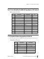
Four-Quadrant (Motoring Dyno) I/O Sub-D . . . . . . . . . . . . . . . . . . . . . . . . . . . . . . . . . . . . .
Parallel Data Acquisition Sub-D . . . . . . . . . . . . . . . . . . . . . . . . . . . . . . . . . . . . . . . . . . . . . .
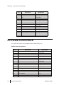
Parallel Control Sub-D . . . . . . . . . . . . . . . . . . . . . . . . . . . . . . . . . . . . . . . . . . . . . . . . . . . . . .
Remote OCS I/O Sub-D . . . . . . . . . . . . . . . . . . . . . . . . . . . . . . . . . . . . . . . . . . . . . . . . . . . . .
RS232 Cable Interconnections . . . . . . . . . . . . . . . . . . . . . . . . . . . . . . . . . . . . . . . . . . . . . . . .
Throttle Controller Interface Sub-D . . . . . . . . . . . . . . . . . . . . . . . . . . . . . . . . . . . . . . . . . . . .
8-1
8-2
8-2
8-2
8-2
8-3
8-3
8-4
8-5
8-7
8-8
Chapter 9 – HELP Message Descriptions
HELP Message Standard Format . . . . . . . . . . . . . . . . . . . . . . . . . . . . . . . . . . . . . . . . . . . . . . 9-1
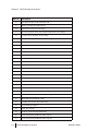
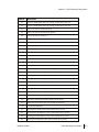
HELP Messages by Number . . . . . . . . . . . . . . . . . . . . . . . . . . . . . . . . . . . . . . . . . . . . . . . . . 9-1
HELP Messages by Category . . . . . . . . . . . . . . . . . . . . . . . . . . . . . . . . . . . . . . . . . . . . . . . . . 9-5
Normal Operation . . . . . . . . . . . . . . . . . . . . . . . . . . . . . . . . . . . . . . . . . . . . . . . . . . . . . . 9-5
Math Exceptions . . . . . . . . . . . . . . . . . . . . . . . . . . . . . . . . . . . . . . . . . . . . . . . . . . . . . . . 9-7
Firmware (ROM) Failures. . . . . . . . . . . . . . . . . . . . . . . . . . . . . . . . . . . . . . . . . . . . . . . . 9-9
Hardware Failures . . . . . . . . . . . . . . . . . . . . . . . . . . . . . . . . . . . . . . . . . . . . . . . . . . . . . 9-10
Chapter 10 – Drawings and Schematics
Index
vi
MAN-DL4-00001
1
Chapter
Introduction
The Dyn-Loc master control unit is the brains of a dynamometer control system. It provides
closed loop digital performance in controlling RPM or torque.
This Master Control Unit is designed for use as a complete eddy-current dyno control and
dyno fields up to 16 Amp rating. For higher field current ratings, a separate field amplifier
module is available for up to 100 Amp fields, up to 480V.
The Dyn-Loc IV is also used as the operators’ interface and closed loop controller for AC
Vector and DC (motoring/loading type) dynamometers. The AC Vector or DC power amplifier
is used as a current/torque function block in the control system.
1.0 Audience
Dyne Systems assumes the following regarding the users of this product.
• Personnel responsible for equipment use have knowledge of dynamometers, engines/
motors, instrumentation related to the testing required, and test procedures required.
• Personnel responsible for electrical connections are registered electricians, with an
understanding of general power and signal wiring, conduit segregation, and the related
devices.
• Personnel responsible for the PLC logic have experience in all the above, plus PLC
programming/use and interlocking concepts.
1.1
Chapter 1
Introduction
2.0 Features
There have been three revisions to this unit over the years, the Dyn-Loc IV/186 being the latest. It
provides the following new features.
•
•
•
•
•
•
•
•
•
•
Data acquisition rates up to 200 hz via special PAL frequency measurement methods.
10 hz display update rate, averaging options to eight seconds.
RS232 port baud rates up to 115,200.
Two wire RS232 operation at any baud rate with no hardware handshake needed.
Extended functions assigned to multiple front panel push-button combinations.
Additional configurability via DIP switches / jumpers.
EEPROM setup storage.
Extended functionality for four quadrant (motoring) dynamometers.
ROM resident EPA road load functions and engine/vehicle inertia simulation (optional).
Windows NT-based terminal emulation software for parameter download or user setup
(optional).
3.0 Location Requirements
For safe and reliable operation, check that:
• All electrical and mechanical connections are secure and in compliance with their respective
schematics in the Drawings and Schematics chapter of this manual.
• The system is installed away from any liquids or condensation.
• The system is safe from physical shock and jarring.
4.0 Safety
To prevent physical injury, follow basic safety precautions when installing, operating, and
maintaining this equipment.
To ensure safe and reliable operation:
•
•
•
•
Follow all instructions in this manual.
Always cancel power to this equipment before removing the cabinet lid.
Obey all safety signs on the equipment and in this manual.
Use proper point-of-operation safeguarding.
For these and other safety precautions, refer to the American National Standards Institute (ANSI)
or the Occupational Safety and Health Administration (OSHA).
1.2
Features
MAN-DL4-00001
Chapter 1
Introduction
4.1 Electrocution Hazard
This product and associated components are electrically energized. Electric shock may cause
serious injury or death. Always disconnect line voltage before servicing the unit or any associated
components.
!
DANGER: Disconnect all power before removing the cabinet lid or servicing the unit
and any associated components. Failure to do so may result in serious injury or death.
Only certified electricians can install this equipment. Unskilled or unauthorized
personnel attempting to install this equipment may cause equipment damage, serious
injury, or death.
4.2 Electrostatic Discharge Damage
Electrostatic discharge (ESD) can damage sensitive microchips and semiconductors on circuit
boards in the PAU cabinet and other internal components. Always wear some manner of ESDgrounding device, such as a wrist strap, when handling internal components.
CAUTION: Failure to observe ESD-grounding precautions may damage sensitive
components.
4.3 Safety Signs and Symbols
4.3.1 System Safety Labels
This test system displays various labels and signs highlighting and explaining caution and danger
areas. Obey these signs when operating this machinery. These signs comply with the American
National Standards Institute (ANSI Z535) and the Occupational Safety and Health Administration
(OSHA 1910.145). The signs depict one of the following conditions:
Danger
Danger signs and labels indicate imminently hazardous situations resulting in death or serious
injury if not avoided.
Warning
Warning signs indicate potentially hazardous situations resulting in death or serious injury if
not avoided.
Caution
Caution signs and labels indicate potentially hazardous situations resulting in minor or
moderate injury if not avoided.
MAN-DS507-00001
Safety
1.3
Chapter 1
Introduction
4.3.2 Documentation Conventions
Some parts of this manual describe information in the form of notes, cautions, and danger signs.
Refer to this section for descriptions of these callouts.
Note:
Notes provide supplemental information related to a procedure.
CAUTION: Cautions with no safety symbol indicate conditions that may cause
equipment damage, or data loss if instructions are not followed exactly as given.
!
CAUTION: Cautions displaying the safety symbol indicate conditions that may cause
physical injury as well as equipment damage, or data loss if instructions are not
followed exactly as given.
!
DANGER: Dangers indicate conditions that may cause death or serious injury if
instructions are not followed exactly as given.
1.4
Safety
MAN-DL4-00001
2
Chapter
Specifications
The Dyn-Loc IV is rated for 277 Vac single-phase line input, which yields a maximum of 250
VDC output with ratings of 16 Adc. This unit requires an isolation transformer(s), rated for the
appropriate voltage and current being handled, for proper operation. This chapter describes the
specification of the Dyn-Loc IV.
1.0 Unit Specifications
1.1 Location
For safe and reliable Dyn-Loc IV operation, check the following.
• All electrical connections are secure and in compliance with the appropriate schematic in
the Drawings and Schematics chapter.
• The unit is installed away from any liquids or condensation.
• The unit is safe from physical shock and jarring.
1.2 Unit Specifications
1.2.1 Mechanical
• 19" x 8.75" x 13" rack/desk/pedestal mounted basic building block.
• Common to both eddy current and four quadrant versions and remote units.
1.2.2 Power Supply Requirements
• 120/240 VAC, 1 phase for control power.
• 240 VAC, 1 phase (phase matched to control power) for field coil power.
• Use of isolation transformer recommended for field coil power.
1.2.3 RPM Transducer Requirement
• 60 (or multiples of 60) pulses per revolution.
• Standard magnetic pickup used with 60 tooth gear.
• Digital encoder.
1.2.4 Load Feedback/Transducer Requirements
• Stain gauge type load cell, 2-3 mV/V (+9VDC excitation and signal conditioner
provided).
• Analog feedback (±1 to 10 VDC).
2.1
Chapter 2
Specifications
1.2.5 Connections
• All signal level I/O via subminiature D or MS connector.
• Exception: H20 Interlock is the signal level, and it is connected via the barrier strip.
• All power I/O by 30 Amp, 300 volt barrier strip.
1.2.6 Control Modes
• All dynamometers.
– RPM or torque with digital setpoint entry.
– Inertia simulation.
• Chassis dynamometers (optional).
– Road load mode configurable via serial port command subset.
– Coast down mode related to road load mode.
1.2.7 Control Origin
• Master/remote/computer with full digital control and instrumentation.
1.2.8 Reference Setpoint Entry
•
•
•
•
•
•
Manually by digital lever wheel switches.
Computer by 16 bit parallel BCD data entry.
Computer by RS232 data entry, ASCII keywords.
Computer by RS232 data entry, BINARY.
Digital reference based on .005%, 1 Mhz crystal oscillator.
Analog reference input, 0 - 10 VDC (scalable).
1.2.9 LAC Entry (Rate of Change Setpoint)
•
•
•
•
•
Computer by binary 8-bit parallel data entry.
Computer by RS232 data entry, ASCII keywords.
Computer by RS232 data entry, BINARY.
Manually by front panel digital lever wheel switches and LAC push button.
Range of 39 - 5,000 units per seconds, standard. Dip switch selectable x1/2 and x1/10
ranges.
1.2.10 Control Regulation and Drift
• RPM – 0 RPM long term, ±RPM short term.
• Torque – 0 ft-# long term, ±LSD short term.
1.2.11 Instrumentation Features
•
•
•
•
•
•
•
•
•
2.2
Microcomputer controlled – 80C186 with 80C187 coprocessor option for road load.
10 hz display update rate.
RPM/torque/power displays to 32,767 units.
Selectable software averaging via DIP switches (8 to 1 range).
Can display averaged, 10 hz or 200 hz data.
Three selectable torque/power decimal places via DIP switches.
Three selectable RPM decimal places via CPU PCB jumpers.
Units are horsepower, RPM, and pound-feet standard. Metric units DIP switch selectable.
Auto span by front panel PB, no potentiometer adjustments.
MAN-DL4-00001
Chapter 2
•
•
•
•
•
•
Specifications
Auto zero by front panel PB, no potentiometer adjustments.
± shunt cal by front panel PB.
Torque linearity – .05% of span calibration point.
Power accuracy – 25 ppm or 1 digit.
Load cell instrumentation temperature stability of 25 ppm per deg. C.
Analog RPM and torque output via rear panel BNC connectors.
1.2.12 Eddy-Current Power Amplifier
• Integral 16 amp., 250 VDC, wide bandwidth, 4SCR regenerative amp (bidir. field
forcing).
• Optically isolated from digital control circuits.
1.2.13 Overspeed/Underspeed Safety
• Overspeed trip at overspeed set point +2 RPM.
– Set by 2 digit overspeed switch.
– 100 RPM resolution.
• Underspeed trip (defeatable) at RPM loss (at less than 2 RPM) during Dyne On.
• OS Relay driver triac.
– NO or NC operation (DIP switch).
– 120 VAC, 0.1 A maximum rating.
• Any trip causes.
– User adjustable braking (defeatable) on eddy current dynamometer.
– Power off and dynamic braking on four quadrant dyno.
– Changing of state of OS triac.
1.2.14 Data Acquisition
• Full duplex RS232 port.
– RPM, torque, and power data in ASCII or binary.
– Status work in ASCII or binary.
• Parallel port – 16 bit binary RPM or signed torque data, simple three wire handshake.
1.2.15 Computer Control
• Parallel port.
– Digital entry or RPM or torque setpoint.
– Digital LAC entry.
– RPM, torque, Dyne On/Off, and Em. Stop mode control by bit sets, filtered edge
control.
– 16 status bits for confirmation of control and monitoring of operation.
• RS232 Port – Same capabilities as parallel port.
MAN-DL4-00001
2.3
Chapter 2
Specifications
1.2.16 Remote Control Unit
• Identical to master unit in appearance.
• Duplicates most front panel control functions of MASTER.
– Speed, torque, and power displays.
– Mode selection.
– Setpoint entry.
– Emergency stop.
– Dyne ON/OFF.
– Fault trip reset.
• Requires 120 VAC @ 0.1 A.
• Interconnection by 37 conductor shielded round ribbon cable, sub D connectors.
• Rack or floor stand mounting options.
1.2.17 DC or AC Four Quadrant Motoring Controls
• Uses the master control unit above, plus an external static power amplifier.
– Wall mounted units to 120 HP @ 500 VDC or 60 HP @ 250 VDC.
– Floor mounted above these sizes.
• Requires 3 phase 240 VAC (250 V armature) or 480 VAC (500 V armature).
• Isolation transformer recommended.
• Specifications identical to the eddy current unit plus the following.
– Motoring/loading capability (in either direction).
– Power saving 3 phase power regeneration during loading.
• Automatic switching between loading/motoring occurs from error signal polarity control.
• Automatic soft transition to setpoint when dyne is turned on (engine off or running).
• Package includes a zero speed directional encoder (speed sensor).
1.2.18 Throttle Controller Option
• Master unit has a dedicated interface to Dyne Systems Company, LLC.’s DTC-1 Digital
Throttle Control, which provides simultaneous control of RPM or torque with digital
accuracy.
2.4
MAN-DL4-00001
3
Chapter
Installation
1.0 Before You Begin
Visually inspect all parts and cross reference all items with the packing slip to ensure that
all components are accounted for and undamaged.
2.0 Signal Wiring Requirements
Enclose all signal circuits in separate conduit from the AC and DC power wiring. Any
other wiring that creates high frequency noise, such as thermocouples, motor switches
etc., must also be separated in this manner.
The excellent performance possible with the Dyn-Loc IV controls are dependent on a
good signal to pulse noise ratio and physical/electrical isolation from any power sources
related to pulse noise generation (including earth grounds). All signal wiring must be
shielded and run in separate conduit from any power wiring. Good spatial separation must
be maintained from SCR wiring or sources connected to any switching type power
amplifiers.
Shield connections must be made to Dyn-Loc common and adequately isolated from any
possible earth grounds. Insure that shield connections are carried through to the device
location.
CAUTION: Do not connect shield at the device location. If the earth ground is
unavoidable, Dyn-Loc IV wiring must be connected in only one place.
2.1 MS Connectors General Information
Multi-conductor cable should be 20-22 gauge, fine stranded, foil type shielding (with
drain wire) with strong insulating jacket. Avoid nicking wires when stripping away jacket
3.1
Chapter 3
Installation
and shield. All connections must be fully inserted and show good solder flow. Avoid excessive
solder wicking. Strain relief of connections with shrink tubing is desirable. Clean soldered area
with flux cleaner and inspect for shorts, etc. Use shrink tubing to cover the area where the jacket
terminates. Use the MS strain relief boot. Follow the rear panel connection labeling.
2.1.1 Load Cell Feedback MS Connector
This requires a 4 conductor cable. It is desirable to minimize the number of series connections for
this device. An unbroken cable run from the load cell to the Dyn-Loc is ideal. Connect the shield
drain wire to the excitation common (Pin D) at the back panel connector. Do not connect the shield
at the load cell.
2.1.2 RPM Feedback MS Connector
Eddy current dynamometers should use an Electro 3030 Magnetic pickup (Mag. PU) or equivalent
transducer. This transducer requires a 2 conductor cable. The transducer air gap should be
approximately 0.010". 60-tooth gear runout should be held to less than ±0.020". Connect the shield
drain wire to the logic common (pin C) at MS connector. Four quadrant (DC or AC motoring)
dynos use a digital, directional RPM transducer supplied. The air gap should be 0.040" ±0.005. If
the transducer cable is to be extended no longer than 35 feet total length, use a low capacity type
cable. Mag PU signals should be checked at a start-up under conditions of increasing dynamometer
field current for possible demagnetization of pickup magnet due to field leakage flux. If the Mag
PU signal decreases significantly as field current increases, de-energize the control and reverse the
field conductor connections. Mark wires F1 and F2. The acceptable Mag PU signal level is 2 - 25
VRMS over operating range.
2.2 Sub-D type Connector Wiring and Part Numbers
2.2.1 General
These connectors are designed for use with a round cable, 20-22 gauge, fine stranded, foil shielded,
drain wire, and jacketed. Before inserting any pins into the connector, slip on the back shell boot
that best fits your cable. Do not put any strain on the wires. Use 3M plastic/plated back shell (or
equivalent) with retaining screws. Note cable 45 degree exit angle desired before installing the
backshell. Follow the pin-out listings and drawings. Female pins are Amp #205090-1, and male
pins are Amp #205089-1.
Remote OCS Ribbon Connector
Use 37 PIN, male, amp #205210-1 (Dyn-Loc end).
If the 37 pin crimp-on connectors are used, care must be taken to orient ribbon properly before
crimping or shorts will occur between conductors. At the end where the shield is to be connected
(to logic Common), extend the ribbon beyond connector 3" for crimping. This provides for a
connection to pin 23 (common). Cut the adjacent wires. Connect the shield to pin 23 by isolating
the ribbon wire to that pin and soldering it to shield drain wire. Fold into the backshell. Ensure no
strain on shield connection. Do not ground the shield. Use a 3M or equivalent backshell with
retaining screws.
Parallel Control Connector
3.2
Signal Wiring Requirements
MAN-DL4-00001
Chapter 3
Installation
Use 37 pin, female, amp #205209-1.
Connect the shield to the logic common at the Dyn-Loc.
Parallel Data Connector
Use 25 pin, female, amp #205207-1.
Connect the shield to the logic common at the Dyn-Loc.
Four Quad I/O Connector
Use 15 pin, male, amp #205206-1.
If the connector is being used for a static DC Dyne control, install jumper 11 to 13. Connect the
shield to the Dyn-Loc common at pin 11 by trimming part of the shield wires off for a good fit into
the crimp pin and jumper wire. Do not connect the shield at the other end.
Serial I/O Connector
Use 9 pin, female, amp #205203-1.
Use a 4 conductor shielded cable, 22 gauge. The drain wire may be used for the common
conductor. A 2-wire hookup may be used (Rx/Tx only), but in this case, CTS and RTS must be tied
together at the Dyn-Loc end. Use a logic common connection.
Throttle Control I/O Connector
Use 25 pin, male, amp #205208-1.
Connect the shield to the logic common at the Dyn-Loc.
3.0 Barrier Strip Connections
Water Interlock Connections Labelled H2O and I.L.
These connections are intended for unpowered normally closed contacts (all in series), indicating
safe to run conditions such as Water Temperature, Water Pressure, or Water Flow.
CAUTION: Do not connect a voltage source (especially 115 VAC) or ground to these
terminals.
The terminal labelled H2O has a +5 VDC open circuit voltage on it with respect to the I.L.
terminal. The short circuit current is limited to 10 to 25 mA. If this voltage/current level does not
provide for reliable operation with the existing safety contacts, ask Dyne Systems for help. One
option is adding in the Dyne Systems OS/US – EMS module where the open circuit voltage is 120
VAC and the short circuit current is 10mA. It also adds other benefits such as providing a logically
OR’ed output for the over/under speed and Emergency Stop fault circuits.
MAN-DL4-00001
Barrier Strip Connections
3.3
Chapter 3
Installation
Connecting these two terminals together through your external safety device will enable normal
eddy current operation. Opening this circuit after one second will inhibit the Dyne On condition or
cause Dyne Off if the dynamometer is on.
Note: Dress away from all power wiring. Although the connection is to the barrier
strip, this is signal wiring. If the wire is shielded, connect the shield to Terminal 1
(H2O).
3.1 Power Wiring General Information
Use an insulated barrel and locking spade lugs on all connections. The wire should fit into the
barrel snugly before crimping. Use an indent crimping tool with a circular lug retainer. The barrier
strip screws are UNC 6-32 size.
3.1.1 GND
Connect a 14-gauge stranded green wire to the GND and to a good system ground. This is a safety
ground to avoid internal power shorts to case and does not tie into any internal circuitry.
3.1.2 L1-L2
This is up to 277 VAC power input to the SCR power amplifier. Use the proper gauge and a fine
stranded wire. An isolation transformer is required. Multiple control installations must use isolation
transformers on each control (preferably tied back to a supply bus) to eliminate undesirable SCR
control interactions. Refer to F1-F2 for additional information on noise content. This power must
be in phase sync with L3-L4. L1 and L2 are not wired if you are using a four-quadrant AC or DC
drive.
3.1.3 L3-L4
This is 120/240 VAC ±10% power input for control circuit power supplies. Input voltage is switch
selectable on main PCB and factory set for 120V. The current drain is 0.2A. Use 14-16 gauge fine
stranded wires. This power must be in phase sync with L1-L2. If the supply bus is 120 or 240 VAC,
it may be connected directly to L3-L4. If not, use a 100 VA isolation transformer to step down the
supply bus to 120 VAC for L3-L4.
Note: If L1-L2 and L3-L4 are isolated from one another, this provides redundant
isolation which reduces SCR pulse noise in the control circuits. This enhances controller
and connected computer systems reliability.
3.4
Barrier Strip Connections
MAN-DL4-00001
Chapter 3
Installation
3.1.4 F1-F2
This is the eddy current field power output. Use the proper gauge fine stranded wire. These wires
carry power with a significantly high frequency content due to the switching characteristic of 4SCR
amplifiers. Keep this separated from all signal wiring. F1 and F2 are not wired if you are using a
four-quadrant AC or DC drive.
3.1.5 OS/US
This is a zero point firing triac switch (Motorola MOC3031 or equivalent. The rating is
120VAC@50 ma. maximum. The triac may be dip switch selected on OS/US PCB (DS255) to be
NO or NC for safe conditions and is meant to drive relays such as P&B KUP type. Do not use this
on solenoids or larger relays. Wire as you would a relay contact, in series with the load relay.
• 120VAC "hot" to left OS/US terminal.
• 120VAC "neutral" to one side of relay coil.
• Right OS/US terminal to other side of relay coil.
4.0 Notes on the Remote Control Unit
Dyne Systems Company, LLC can provide a slope front pedestal mounting, or a pedestal mount for
the standard enclosure. Maintain at least five feet separation from vicinity of the engine for ignition
type engines to prevent ignition noise interference in the unit.
4.1 Wiring the Remote Unit
• A 37 conductor round, shielded cable should be used for interconnection. Connection is to be
made to the same pin numbers at each end, unless special functions are being provided (see our
job specifications), shield to logic common. Avoid earth ground connections, any grounding in
the system should be at the master unit logic common.
• The shielded cable should be treated as low signal level wiring and so be isolated from all but
signal wiring. Conduit must be carried up close to the unit to provide shielding against cell
noise sources.
• The 120VAC power for the unit may be obtained from any clean source; the unit requires only
50VA of power.
• Refer to the "Remote OCS Ribbon Connector" section if you need assistance.
MAN-DL4-00001
Notes on the Remote Control Unit
3.5
Chapter 3
3.6
Installation
Notes on the Remote Control Unit
MAN-DL4-00001
4
Chapter
Display Set-Up and
Maintenance
1.0 Before You Begin
• Do not proceed with this chapter until the Dyn-Loc has been installed according to the
guidelines in the installation section of this manual.
• Do not proceed with the Torque Display Calibration portion of this chapter without
allowing a minimum of 15 minutes warm-up from the time the AC power is applied.
2.0 Overview
The Dyn-Loc IV display system is microcomputer-based. This provides flexibility in
calibration range, data averaging, and data acquisition.
• Speed data is entirely digital. There are no a/d or d/a converters in the system.
• Torque data is acquired from a high quality instrumentation amplifier providing
digitally controlled gain for the strain-gauge over a range of 18 to 750 in 16,000
discrete steps and digitally controlled zero offset over a range of ±12,000 units.
Temperature stability is typically ±25 ppm/deg C.
• Power is calculated to 32 bits, uncorrected for ambient engine conditions.
• PAL devices are used to digitally measure the speed or torque channels at up to 200
times per second, allowing for fast data acquisition and therefore fast calibration.
.1
Chapter 4 Display Set-Up and Maintenance
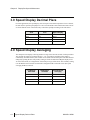
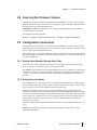
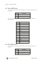
3.0 Speed Display Decimal Place
For most applications, the speed display will not require a fractional component. If one is desired,
the unit must be opened up and jumpers 13 and 14 on the DS503 CPU board located. JP13 and 14
are on the bottom center of the board. They control the speed dp according to the chart below.
JP14
JP13
Speed Display
OUT
OUT
00000
OUT
IN
0000.0
IN
OUT
000.00
IN
IN
00.000
4.0 Speed Display Averaging
The microprocessor displays a moving window average of the latest N seconds of 10hz speed data.
The user has the option of averaging the last 1, 2, or 4 seconds of speed data. This setting is
controlled by two DIP switches, one of which is accessible from the front panel. The other must be
changed by opening the unit. The primary setting is switch #8 under the TORQUE display bezel.
To access this switch, use a fingernail or soft slim object to pry off the bezel. The secondary setting
is on the DS503 CPU board, the switch block is designated SW1 on the silk-screen (the speed
averaging doubler) switch #4.
TQ Display
Switch #8
4.2
DS503 SW1/
Switch#4
Seconds Speed
Averaging
OFF
OFF
1
ON
OFF
2
OFF
ON
2
ON
ON
4
Speed Display Decimal Place
MAN-DL4-00001
Chapter 4 Display Set-Up and Maintenance
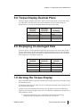
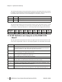
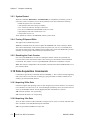
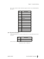
5.0 Torque Display Decimal Place
The torque display fractional component is easily set from the front panel. To access this setting,
use a fingernail or soft slim object to pry off the TORQUE bezel. Set switches #4 and 5 as
displayed below. The power decimal point matches the torque decimal point.
TQ Display
Switch #5
TQ Display
Switch #4
TQ Display
OFF
OFF
00000
OFF
ON
0000.0
ON
OFF
000.00
ON
ON
00.000
6.0 Displaying Un-Averaged Data
To observe the raw or un-averaged data being read by the microprocessor from the PAL system,
open the unit and locate the SW1 switch block on the DS503B CPU board. The 10hz and 200hz
raw data can be made to appear on the displays as indicated in the table below. Note: The 200 hz
data is displayed at a 10hz display update rate.
DS503 SW1/
Switch #2
DS503 SW1/
Switch #3
Data Display
Override
OFF
OFF
NONE
OFF
ON
200 hz
ON
OFF
10 hz
ON
ON
ILLEGAL
7.0 Zeroing the Torque Display
Refer to the HELP number descriptions for HELP xxxx messages appearing on the display during
this calibration process.
Assuming the display shows an offset of at least 1 Least Significant Digit (LSD) zeroing the offset
may be performed as follows.
Complete a Zero at the beginning of the work day. See the Shunt Cal section for another daily
suggestion. Note any large changes as they may be an indication of malfunction in the load cell or
signal conditioner circuits.
1
Ensure the dynamometer is free of external forces and the load cell mounting
configuration prevents application of any lateral forces to load cell.
MAN-DL4-00001
Torque Display Decimal Place
4.3
Chapter 4 Display Set-Up and Maintenance
2
Exert a temporary force on the dyne in the loading direction while observing the torque
display polarity. Reverse leads B and C on the load cell MS connector if the torque sign is
not positive for engine loading direction.
3
Press the Auto Zero button for ½ second using a pencil tip or small soft device. The
display flashes and steps rapidly to zero. The computer needs a 0 ±2 reading. This process
may take from 2 to 10 seconds. Perform the zero a second time if the first zero leaves a
non-zero low value. An extremely large zero offset (>20,000 counts) may prevent a
complete AZ in the allowed time period. In this case, the data will be rejected and
previous settings will retained. It may be necessary to temporarily balance out part of the
offset in order to obtain a zero, then remove the balance weights and complete the zero
process. Subsequent zero procedures should not require this manipulation.
4
Repeat the ZERO and SPAN operations at least once to check for interaction. Data from
this process is stored in non-volatile memory so calibration need not be repeated after
power ON/OFF/ON cycling. Be aware that zero data will be lost if the system defaults are
set. Allow 15 minutes for warm up in all cases then check zero and span to satisfy yourself
that it is repeatable.
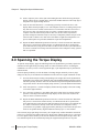
8.0 Spanning the Torque Display
To span the torque display, apply the calibrating load to the dynamometer (preferably equal to the
maximum for the application) preventing motion or contact with other surfaces. Assuming the
calibration is in error by at least ±2 least significant digit, a span adjustment may be performed as
indicated below.
Check the Span periodically or when the shunt cal reading changes drastically. Note any large
changes as they may be an indication of malfunction in the load cell or signal conditioner circuits.
1
Set in the desired torque reading corresponding to the weights used on the dynamometer
multiplied by the length of the calibrating arm using the RPM/TORQUE digital switches
which are presently ACTIVE. Take into account the torque decimal point and the desired
torque units. Refer to the Power Display Setup section if you need additional information.
2
Press Auto Span for ½ second. The display flashes and steps rapidly to the same reading
set in on the digital switches.
3
If it is necessary to Span to a value higher than can be input on the leverwheel switches,
position 1 of the dip switch under the Torque display can be used to add 10,000 to the
value set on the leverwheel switches.
4
Repeat the ZERO and SPAN operations at least once to check for interaction. Data from
this process is stored in non-volatile memory so calibration need not be repeated after
power ON/OFF/ON cycling. Be aware that span data will be lost if the system defaults are
set. Allow 15 minutes for warm up in all cases, then check zero and span to satisfy
yourself that it is repeatable. Apply approximately half the previous load to the dyne and
check for acceptable linearity. Signal conditioner linearity spec is ±.05% FS max.
If an extremely large span change is necessary, the computer may oscillate around the desired AS
point. If so, it will reject the settings and revert to the previous readings. In this case, it is necessary
to set the digital switches midway to the desired calibration for the first Span attempt, then to the
true calibration point for the second attempt using the weights based upon the true AS point.
4.4
Spanning the Torque Display
MAN-DL4-00001
Chapter 4 Display Set-Up and Maintenance
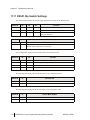
9.0 Using the Shunt Cal Button
Perform the Zero/Span process before attempting to use the Shunt Cal button.
Shunt Cal is a repeatable unbalance of the resistor bridge which makes up all load cells. It is
intended to be used as a means of checking calibration and as a means of actually calibrating
without hanging weights.
Perform the Zero/Span process before attempting to use the Shunt Cal. button.
1
Perform an accurate calibration using weights, then remove the weights.
2
Push the SHUNT CAL PB (hold it until the display stops changing).
3
Record the value on the front panel display.
4
Repeat steps 2 and 3 for the other direction.
5
If you need to check the instrumentation, check the Shunt Cal against the previously
recorded value. If the check reveals a difference as follows, span the control to the original
shunt cal reading. Set the desired shunt cal on the active leverwheel switches. Push AUTO
SPAN and SHUNT CAL simultaneously. The control will span in the direction last read to
the shunt cal value.
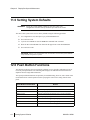
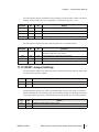
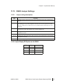
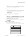
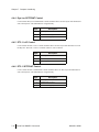
10.0 Power Display Setup
The following switch settings will be partially or completely overridden if the display unit’s
commands are used to set the system for chassis dyno/road load operation.
The power display can be set to use several different sets of units for its calculation. To access this
setting, use a fingernail or soft slim object to pry off the TORQUE bezel. Set switches 6 and 7 as
indicated below.
TQ Display
Switch #6
TQ Display
Switch #7
TQ Units
Power Units
OFF
OFF
Pound Feet
Horsepower
OFF
ON
Pound Inches
Horsepower
ON
OFF
Newton Meters
kiloWatts (kW)
ON
ON
Newton Meters
Horsepower
MAN-DL4-00001
Using the Shunt Cal Button
4.5
Chapter 4 Display Set-Up and Maintenance
11.0 Setting System Defaults
WARNING: Setting the system defaults completely resets the system. Any
configuration accessible strictly via RS232 port will also be erased.
The entire CPU system can be reset to factory defaults using the following procedure.
1
Use a fingernail or soft, slim object to pry off the POWER bezel.
2
Set switch #4 to ON.
3
Cycle the AC POWER or issue the REBOOT command from a terminal.
4
Short the JP5 on the DS503B CPU board on the upper front corner labeled RESET.
5
Set switch #4 to OFF.
CAUTION: Failure to set switch #4 back to off will cause a reset to the system defaults
every time the AC power is cycled.
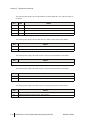
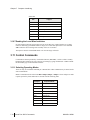
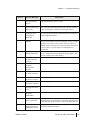
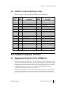
12.0 Push Button Functions
The firmware in the Dyn-Loc IV/186 assigns a function to every possible combination of one or
two front panel push buttons. The following table displays all combinations and will therefore
duplicate the basic single button functions.
The special push button functions are primarily for troubleshooting, however, some contain some
useful functions for normal operation such as querying the current LAC setting from the front
panel.
Push Button Combination
4.6
Result
LAC SET
Set MAN mode LAC from lever wheels.
AUTO ZERO
Zero the TQ display
AUTO SPAN
Span TQ display from lever wheels
SHUNT CAL
Activate FET shunt (alternating sign) of load cell bridge
AUTO SPAN + SHUNT CAL
Span TQ display using FET shunt
LAC SET + AUTO ZERO
Show AZ D2A setting on TQ display
LAC ST + AUTO SPAN
Show AS D2A setting on TQ display
LAC SET + SHUNT CAL
Show firmware revision on display
Setting System Defaults
MAN-DL4-00001
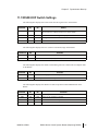
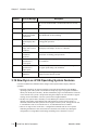
Chapter 4 Display Set-Up and Maintenance
Push Button Combination
Result
AUTO ZERO + SHUNT CAL
Memory Test (any button to stop)
AUTO ZERO + AUTO SPAN
Reboot
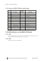
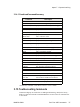
Use the following table to determine the effect of the LAC SET push button according to the lever
wheel settings.
Lever Wheel Setting
Action
0
Display current setting
1
Set to RAPID
2
Calibrate REF CLOCK (always done at bootup)
3
Exit from REF CLOCK calibration
4
Display crash recovery counter
5 - 38
Invalid LAC value (HELP 0 39-5000)
39 - 5000
Valid LAC settings in controlled variable units/second
5001 - 9999
Invalid LAC value (HELP 0 39-5000)
Note:
MAN-DL4-00001
Certain valid leverwheel settings will round to valid LAC settings.
Push Button Functions
4.7
Chapter 4 Display Set-Up and Maintenance
4.8
Push Button Functions
MAN-DL4-00001
5
Chapter
Dynamometer Startup
Procedure
Before You Begin: Do not start the dynamometer until the Dyn-Loc has been
installed and set up according to the instructions in this manual.
1.0 Wiring and Conduit Checks
Use the following tips when checking the wiring and conduit.
• For common wiring raceway/conduit for signal and power wiring, all power must
be in separate raceway from signals.
• Do not tie the Dyn-Loc L1-L2 in parallel with L3-L4! The L3-L4 must be taken
from a clean AC line in phase with L1-L2.
• Earth ground on magnetic pickup (Mag. PU) and/or load cell shields. All DynLoc circuits are floating with respect to GND. Shields tie to Dyn-Loc common at
connector in question.
• Multiple series connections and/or cold solder in load cell wires. These faults
increase the likelihood of loose connections, thermal signals, and higher noise
susceptibility in the torque transducer loop. This will show up as increased drift and
intermittent torque display problems.
• Several Dyne Controls’ SCR amplifiers tied to same power lines. Without
isolation transformers, this set up may seem to work in some instances, but it will
produce seemingly unpredictable transients in some of the controls. dV/dt notches on
the common power line from one control will sometimes trigger SCRs on another
control, therefore, separate isolation transformers are imperative in these applications.
.1
Chapter 5 Dynamometer Start-Up
2.0 Load Cell Checks
The load cell assembly mechanical connections and dynamometer assembly wiring and mechanical
connections must be such as to minimize extraneous forces on the system.
• Load cell is mounted such that no lateral forces are applied. Only forces normal to the load cell
mounting point are applied. At least one very free pivot point must be provided to minimize
vibration induced and off-normal forces on load cell. Field and interlock wiring devices must
be very flexible and formed in a loop at entry point.
• Cooling water and other connections at the dynamometer must be made with very flexible
material. The material must be long enough, with an entry parallel to the dynamometer’s axis
and in a neutral position to minimize unmeasured and non-repeatable forces on the
dynamometer’s assembly.
• The load cell rating should be reasonable for the application. Undersizing may result in failure,
but extreme oversizing will result in excessive zero/span drift. Temperature drift is related to
full scale load cell rating, so using a load cell of two times the rating required will result in two
times the drift.
• The dynamometer trunnion bearings must be properly lubricated and free or they will
introduce a non-repeatable hysteresis into the static torque calibration. Check for paint, grit,
etc. in areas between the dynamometer’s free section and the dynamometer’s static section.
• Check that torque/power decimal point placement is correct for your application. If the
placement results in a maximum display of more than 4,000 units, the torque display will
function properly, but the torque control loop may be unstable due to the high loop gain.
2.1 Checking Load Cell Mechanics
Use the following procedure to check load cell mechanics with no prime mover connected.
5.2
1
With the dynamometer in a zero torque condition, press down on the calibrating arm.
2
Slowly release the pressure.
3
Note the reading on the torque display including polarity.
4
Repeat the above steps pulling up on the calibrating arm.
5
Compare the two readings. A difference of zero indicates very good condition. If the
difference is greater than two units, recheck the dynamometer for sources of hysteresis
torque.
Load Cell Checks
MAN-DL4-00001
Chapter 5 Dynamometer Start-Up
3.0 Setting the Current Limit
Use this procedure for eddy current dynos only.
If your dyno requires over 16 amps, use an external field power amplifier (model DS507 available
from Dyne Systems Co., LLC).
The current limit adjustment is made on the DS256 PCB (left side panel), CFB potentiometer. This
adjustment allows adapting to a wide range of dyno capabilities, provides protection of the field
coil, and affects stability of the control system. You should also check that rear panel fuse sizing is
such to protect for a continuous over-voltage condition in case of power unit failure.
1
Turn the CFB potentiometer fully CW (minimum field current).
2
Connect the meter to measure either field current or voltage.
3
Turn the FAULT BRAKE potentiometer (VR8 on DS501 PC board) fully CW.
4
Determine the actual field rating. If the field has been rewound, the rating may have
changed.
5
With the dyno at a standstill and all power ON, press the DYNE ON PB button. If all
interlocks are made, the control should latch DYNE ON. If the DYNE ON lamp drops out,
check the H2O Interlock. If the underspeed trip has not been disabled, the Dyn-Loc should
trip after about one second. This will cause the OS/US RESET PBPL to light and a high
braking condition (current limit) on the field. If UNDERSPEED has been disabled, push
EM STOP.
6
Turn CFB Pot CCW until you just achieve maximum desired field current/voltage or just
reach the maximum available output from the Dyn-Loc (approximately 200 VDC with
240 VAC input). Do not set to exceed the field rating. Field voltage should be equal to the
product of rated current and coil resistance at the time of the adjustment.
7
Push DYNE OFF PB and OS/US RESET PBPL simultaneously. Leave the meter
connected for the next test.
4.0 Setting the Emergency Stop Level
Use this procedure with the meter still connected to the dyno coil.
1
Push DYNE ON PB then quickly push the EMERG STOP PB.
2
Confirm that the EM. STOP RESET PBPL extinguishes, and that full braking power is
again applied to coil.
3
Adjust VR8 on DS501 PC board (labeled FAULT BRAKE) for the desired field current
during fault condition.
4
Push EM. STOP RESET PBPL, then DYNE OFF PB and OS/US RESET PBPL
simultaneously to reset the control.
MAN-DL4-00001
Setting the Current Limit
5.3
Chapter 5 Dynamometer Start-Up
5.0 Checking Magnetic Pickup
The Mag. PU/60 tooth gear system is critical to achieving the full system potential. The Electro
3030 or equivalent and 12 pitch gear is recommended.
1
Check for conformance to installation section wiring requirements. The sensed gear
should be a 12 pitch beveled type, securely attached to the shaft. If the set screws are the
primary retaining means, 3 #10 screws at 120º spacing are best. The shaft should have a
flat for each screw and Loc-Tite should be used. Ensure any holes in the gear are not in a
path to be measured by the pickup.
2
Check the gear on the dyno for less than .001" runout and damaged teeth. Either will affect
control performance.
3
Ensure the Mag PU mounting should be stable, provide ease of air gap adjustments and a
good flux path.
4
Clean out any iron chips in the air gap.
5
Set the air gap for 0.010".
6
Rotate the dyno rotor and check for variations.
7
If the bearings have excessive play, increase the air gap to avoid damaging the Mag PU.
8
Turn the dyno with the engine.
9
If an oscilloscope is available, check the Mag PU signal for good waveform and signal
level per the control specs. A 10 percent modulation envelope indicates acceptable runout.
10 Check the displayed speed against another reliable source to confirm the proper sensing.
6.0 Stability Adjustments
Factory adjustments of the main control board(s), number of counts, gain, d SPD/DT, and SPEED
LEAD usually provide good stability, response, and settling time. Performance checks will allow
determination of any necessary changes. The CFB Pot is the only adjustment that affects torque
mode stability. All adjustments affect the RPM mode. The DS503 CPU board’s TQ_FILTER pot
should be at 50 percent.
Factory settings for the control boards are listed in the table below.
Control Board
5.4
Setting
# COUNTS (DS502 SW2)
All ON
GAIN Pot. (DS502 VR1)
20% CW
dSPD/dT Pot. (DS501 VR4)
60% CW
SPEED LEAD Pot. (DS501 VR6)
50% CW
Checking Magnetic Pickup
MAN-DL4-00001
Chapter 5 Dynamometer Start-Up
7.0 Performance Checks
1
Run the engine near peak torque speed at a wide open throttle (governor disabled). The
engine itself must turn smoothly in order to perform the following tests.
2
Observe the RPM display, lock light, and sound of the engine.
–
–
If the RPM display is steady at the set point, the lock light is steady on, and the engine
sounds as if it were running smoothly, no adjustments are necessary.
If the RPM display regularly deviates more than ±1 digit, the lock light flickers, and
the engine sound indicates no missing but variable speed, slowly turn the dSPD/DT
adjustment clockwise until the control stabilizes.
3
Repeat steps 1 and 2 at several setpoints to check overall performance.
4
Set LAC to 200.
5
Set the upper and lower digital setpoint switches for large changes in setpoint.
6
Perform several cycles of setpoint change and observe the RPM display for overshoot and
settling time to new operating point.
–
–
–
If the overshoot is 1 percent or less of the dyne/engine maximum speed rating and
settling to ±2 RPM requires 2 cycles or less, no improvement is likely with
adjustments. Continue this procedure. If a change has been made to #-of-COUNTS,
restart this procedure.
If the overshoot and/or settling exceeds these specs, turn SPEED LEAD Pot CW to 75
percent and recheck the transients. A SPEED LEAD setting above 50 percent may
cause noise induced instability if there is more than 5 percent Mag PU modulation.
If the SPEED LEAD adjustment does not achieve the desired results, throttle back to
a no load condition. Go to the #-of-COUNTS dip switch and set #1 to OFF. This
requires a brief check of worst case conditions in steps 1 through 5 where you may be
able to reduce the dSPD/DT setting if desired. Continue this procedure. There should
be a substantial decrease in overshoot and settling. Count #2 switch may be set to
OFF also, if necessary. If the result is still undesirable, contact the factory.
7
Operate the engine in RPM modes as in step 1.
8
Perform the transfer to Torque mode, pre-loading the TQ display value into the not active
leverwheel. Operate at several combinations of throttle and Torque setpoint. Set the
Torque display DIP switch for minimum averaging.
–
–
–
MAN-DL4-00001
Dyne control should regulate to ±1 digit of setpoint for all combinations. The lock
light should be On during all steady-state torque conditions if good dyno-engine
mechanical conditions exist. Otherwise, the lock light may not show a steady
indication. If the torque display shows ±1 digit maximum variation, the system is
performing properly and no further action is needed.
If the torque loop is not stable, turn the TQ_FILTER pot CCW slightly. If the
condition worsens, turn it CW slightly past 50 percent of the factory setting.
If the lock light flickers and display shows more than ±2 digits variation, check
DS503B CPU Board TQ_FILTER Pot. adjustment. If necessary, turn the CFB Pot
(DS256A PCB) very slowly CW until display stabilizes. If more than a 10 percent
change was necessary in CFB Pot adjustment, recheck the mechanical system and
torque decimal placement. If no changes in decimal placement or mechanical system
Performance Checks
5.5
Chapter 5 Dynamometer Start-Up
–
were found necessary, maintain the adjustment and restart the procedure for spot
checks on performance.
Reset the torque display averaging DIP switch to desired value.
8.0 Overspeed Trip Setting
1
On the Dyn-Loc rear panel, locate a two-section thumbwheel assembly labeled
OVERSPEED TRIP.
2
Determine your maximum safe system RPM and set these switches for that value (divided
by 100).
A trip will occur if the speed exceeds this setting for more than ½ second. Since this is a digital
circuit, no adjustments are required. An overspeed trip will cause energization of the field at rated
current, and change the state of the triac which is accessible on the rear panel barrier strip. The triac
is rated at 50 ma, 120VAC max, and is meant to drive a pilot relay controlling such items as
ignition, fuel, etc.
9.0 Other Control System DIP Switch,
Jumper, and Adjustment Options
9.1 DS255 DIP Switch A
• Section 2 controls underspeed trip protection. If the DYNE is ON and no speed signal is
received, a US Trip may occur causing dyno braking (adjustable), and change of state of the
OS/US triac.
–
–
–
Section 2 OFF will enable this protection.
Section 2 ON will disable this protection.
Overspeed Trip will always be enabled.
• Sections 3 and 4 control the OS/US triac operation for a trip condition.
–
–
–
–
Section 3 ON and 4 OFF will provide an NC triac state.
Section 3 OFF and 4 ON will provide a NO triac state.
Section 3 ON and 4 ON is not recommended or useful.
Both sections OFF will defeat triac change of state.
9.2 DS105C Jumpers and DIP Switches
DIP switches A and B control the PIN F (only) encoder input and provide divide down of this input
over a range of 1:1 to 512:1.
• 1:1 factor: SWB(3) only, closed.
• 2:1 factor: SWB(2 and 4) only, closed.
• 4:1 factor: SWB(1 and 4) only, and SWA all open.
5.6
Overspeed Trip Setting
MAN-DL4-00001
Chapter 5 Dynamometer Start-Up
• Using the remaining SWA settings you may obtain up to 512 division, in a binary sequence.
SWB(4) must be closed for all divide down situations. Contac Dyne Systems’ Service
Department if you need assistance.
Jumpers
• JP1, JP2, Ra, and Rb provide means for single ended high level input to the load cell signal
conditioner for use with a torque shaft signal conditioner.
–
–
–
Normal load cell applications require JP1 Out and JP2 In, with Ra and Rb Out.
For high level single ended inputs, connect Torque MS(C) to MS(D), and signal input
to MS(B) with MS(D) as Common.
Ra and Rb are proportioned for dividing down the max signal input to approximately
50 mv max. JP1 is In and JP2 is Out for this application. Ra and Rb must be metal
film low drift resistors. Rb must be approximately 350 ohms.
• JP3 controls the Analog Torque output polarity.
–
–
JP3(A-B) position provides positive output with positive display polarity.
JP3(A-C) provides reversed polarity of Analog output.
These DIP switches must be set to provide a 60 pulse per revolution square wave to the Dyn-Loc;
therefore, the SWB(4) section must route the signal through a flip-flop. Contact Dyne Systems’
Service Department if you need additional assistance.
10.0 DS105C Analog Torque and Speed
Output Adjustments
These circuits are factory adjusted for 1 mv/RPM and 1 mv/Torque Unit.
10.1 Analog RPM
1
With a zero RPM display condition, adjust RPM Zero Pot for 0±1 mv output at TP1 with
respect to TP2.
2
Input your application’s maximum RPM using a signal generator into the RPM MS
connector pin F with respect to PIN C (to +5V level square wave). Temporarily set the
DS501 SW3 switch 3 on and switch 4 off, if necessary. You may get an Overspeed Trip if
you exceed that setting; to avoid this, temporarily increase the OverSpeed setting.
3
Adjust RPM Cal Pot for the desired reading.
4
Repeat the above steps until no further change is required.
5
Remove MS(F) generator and return the Overspeed Trip thumbwheels to the proper
setting.
6
Reset the DS501 SW3 to its previous setting.
10.2 Analog Torque
1
With a zero torque display condition, adjust the TQ Zero pot for 0±1 mv at TP3 with
respect to TP4.
MAN-DL4-00001
DS105C Analog Torque and Speed Output Adjustments
5.7
Chapter 5 Dynamometer Start-Up
2
Apply the rated torque to the dyno.
3
Adjust the TQ SPAN pot for the desired Analog output. The AutoSpan function may be
used to vary the torque value.
4
Repeat the above steps until no further change is required.
5
Adjust the TQ Filter pot for desired filtering of the Analog output.
6
If the span was changed, recalibrate the load cell display and remove the torque load from
the dyno.
11.0 DS500 Series Control System Boards
(Replacing DS250)
These newer Dyn-Loc IV controls have three new boards installed, replacing the DS250 board.
These new boards have a number of new features.
11.1 DS500 Power Supply PCB
• The DS500 has a new, more robust switching power supply. It is designed to operate with a
wider input range of 90-140 Volts AC input on L3 and L4 (if using 120VAC control power).
• The user still has a choice of 120/240VAC control power selected via an internal switch.
11.2 DS501/502 Reference Generator and Control PCBs
Many old style chips have been replaced with newer EPLD chips. This provides much higher
component density and has allowed for many new improvements to be added.
• Significantly faster response during speed changes in RPM mode are now possible, without
DV/DT interaction.
• More accurate TQ control at light TQ loads.
• Change from standard to one-tenth LAC via internal DIP switch for a wider selection of
setpoint ramp rates.
• Instant loading of active lever wheel setpoint when the dyno is on.
• Adjustable fault braking on eddy current type dynamometers during an EM Stop, or OS/US
faults.
• Motoring TQ mode is automatically selected either via external inputs or RS232 control.
Available only on motoring type dynamometers.
• Enhanced serial communications by elimination of the hardware handshake requirement. A
software handshake is still required in most cases.
• Magnetic pickup or Encoder signal input is now selected via internal DIP switches. This must
be coordinated with the wiring.
5.8
DS500 Series Control System Boards (Replacing DS250)
MAN-DL4-00001
Chapter 5 Dynamometer Start-Up
11.3 Enabling a 1/10th LAC Mode
During normal operation the Dyn-Loc’s LAC rate is adjustable from 39 to 5000 units per second.
When the 1/10th LAC mode is enabled the LAC rates change to 3.9 to 500 units per second. To
enable this, turn off the DIP SW1-4 located on the DS502 board.
11.4 Setting up Speed Signal Input Source
Select the type of speed feedback input source you are using. The following DIP switches are
located on the DS501 board as indicated in the table below.
SW3-3
SW3-4
SW1-1
SW1-2
SW1-3
Setting
OFF
ON
OFF
OFF
OFF
Two wire magnetic pickup.
ON
OFF
OFF
OFF
OFF
Encoder pickup non-direction sensitive.
ON
OFF
ON
OFF
OFF
Encoder pickup with direction bit output.
ON
OFF
OFF
ON
OFF
Encoder pickup with direction derived from two
change encoder signal.
ON
OFF
OFF
OFF
ON
Encoder pickup with direction derived from two
channel encoder signal but inverts the direction.
11.5 Adjusting the Fault Braking on Non-Motoring
Dynamometers
When the Dyn-Loc goes into an EM Stop or Over Speed/Under Speed trip, it will normally apply
full current to the dynamometer coil. In some instances this is not desirable, so a 0 to 1 percent
brake adjustment has been added. If an EMS or OS/US fault occurs, the Dyn-Loc will apply the
brake preset current or control loop braking current, whichever is greater.
11.5.1 Method One
Use this method to set up without energizing the field winding.
1
Remove the top of the Dyn-Loc.
2
Install the negative (black) lead of a volt meter to TP11 on the DS501 board.
3
Attach the other lead (red) to TP8 to the DS501 board.
4
Confirm the Dyn-Loc is in RPM, MASTER mode and the dyno is not spinning.
5
Set in a setpoint of about 500 RPM or more on the active lever wheel switches. The
voltage at TP8 goes to about 0 volts.
6
Press EM STOP on the Dyn-Loc. The voltage at TP8 increases.
7
Find the pot labeled FAULT BRAKE on the DS501 board. The usable range on the pot is
from 0 (no fault braking) to 12 (maximum braking) volts.
8
Adjust the voltage for the desired percentage of the maximum level of braking torque.
9
Remove the volt meter.
MAN-DL4-00001
DS500 Series Control System Boards (Replacing DS250)
5.9
Chapter 5 Dynamometer Start-Up
10 Replace the Dyn-Loc lid.
11 Reset the Dyn-Loc out of its fault condition.
You must still set up the DS256A power amplifier CFB pot for desired maximum field current
without exceeding the dyno name plate rating. This setting must be in excess of what is required to
stall the engine under test.
11.5.2 Method Two
This method requires the dyno coil to be connected to the Dyn-Loc. The eddy current power
amplifier should have its current limit adjustment (CFB pot) properly set.
1
Remove the top of the Dyn-Loc.
2
Install a DC volt meter across the field on the eddy current dyno. The two field fuses on
the back of the Dyn-Loc can be temporarily removed so that you can safely install the
meter.
3
Replace the fuses.
4
Confirm the Dyn-Loc is in RPM, MASTER mode, and the dyno is not spinning.
5
Set in a setpoint of about 500 RPM or more on the active lever wheel switches.
6
Press EM STOP on the Dyn-Loc. The voltage across the field jumps up and settles down
at the voltage level.
7
Find the FAULT BRAKE pot on the DS501 board.
8
Adjust the pot to get the desired level of braking voltage across the coil you want during a
fault.
9
Confirm this is adequate to stall the engine under test.
10 Remove the volt meter.
11 Replace the Dyn-Loc lid.
12 Reset the Dyn-Loc out of fault condition.
11.5.3 Method Three
This method requires the dyno coil to be connected to the Dyn-Loc. The eddy current power
amplifier should have its current feedback properly adjusted. You must provide for sufficient
torque during a fault stop to stall your largest engine.
5.10
1
Remove the top of the Dyn-Loc.
2
Turn the FAULT BRAKE pot on the DS501 board fully CCW.
3
Start the engine.
4
Set the desired speed setpoint.
5
Turn on the dyne.
6
Open the throttle until you get the desired torque load.
7
Press EM STOP. Nothing should happen at this point.
8
Begin slowly turning the FAULT BRAKE pot CW until you get the level braking you
want. The speed decreases and the torque level increases until the engine stalls.
DS500 Series Control System Boards (Replacing DS250)
MAN-DL4-00001
Chapter 5 Dynamometer Start-Up
9
Replace the Dyn-Loc lid.
10 Reset the Dyn-Loc out of the fault condition.
11.6 Enhanced Torque Circuit
The enhanced torque circuit is now polarity sensitive. This sensitivity can be defeated by turning
off DS502 SW2-Section#4. When connecting the load cell to the Dyn-Loc, the torque display must
display a positive torque when the dyno is loading the engine. If this is not done, the torque
feedback will be wrong polarity (regenerative), and the Dyn-Loc will stall the engine in torque
mode.
11.7 Using Motoring Torque Mode
This is only available on motoring dynamometers.
11.7.1 Master Mode
When in master mode, you should be in torque mode with the dyne on and the engine running. You
will notice when you dial in a torque value on the active lever wheel switches, it only loads the
dyno producing a positive torque value. To go into motoring torque mode, apply +5 volts to pin 2
of the remote OCS connector found on the back of the Dyn-Loc. You can also jumper pins 2 and 30
together to get the same results.
11.7.2 Computer Mode
Refer to the section on RS232 port usage for method(s) of requesting a negative torque setpoint.
11.8 Instant Loading of a New Setpoint
You do not have to wait for the Dyn-Loc to LAC (ramp) to the new setpoint before you can turn the
dyne on. The Dyn-Loc now loads the Active lever wheel switch value instantly when the Dyne On
button is pressed.
11.9 Number of Counts DIP Switches
This is an RPM loop response adjustment. Set the DS502 SW2 switch positions 1 off or 1 and 2
both off to achieve a much faster speed integrator action. GAIN pot adjustment is no longer
required. Switch 3 is not used and is set aside for future use.
11.10 Enhanced DV/DT Circuit
There are two choices in dSPD/dT (previously DV/DT) methods in RPM mode.
• Move Jumper 4 to Jumper 3 position on the DS501 to enable the old DV/DT mode.
• Move Jumper 3 to Jumper 4 position to enable the new dSPD/dT mode. This new dSPD/DT
mode allows the dyno to make faster speed transitions without the dSPD/dT circuit hampering
the dyno’s response.
• This would also affect dTQ/dT, which is rarely used.
MAN-DL4-00001
DS500 Series Control System Boards (Replacing DS250)
5.11
Chapter 5 Dynamometer Start-Up
11.11 DS501 Dip Switch Settings
The following tables display the encoder input configuration settings for the DS501 board.
Switch #
#1
#2
#3
Function
SW1
ON
OFF
OFF
Enables encoder direction input on pin D.
SW1
OFF
ON
OFF
Gets direction from channels 1 and 2 of encoder.
SW1
OFF
OFF
ON
Gets direction from channels 1 and 2 of encoder but
inverts the direction.
Switch #
#4
SW1
OFF
Normal operation with 60 tooth gear (PPR input)
SW1
ON
Doubles input frequency only when encoder channels 1 and 2 are both used.
Should only be used with a 30 tooth gear.
Function
The following table displays the speed signal source on the DS501 board.
Switch #
#1
#2
Function
SW3
ON
OFF
Enables encoder input.
SW3
OFF
ON
Enables mag-pickup input.
SW3
OFF
OFF
Not valid.
SW3
ON
ON
Not valid.
The following table displays the encoder direction circuit on the DS501 board.
Switch #
#1
Direction Bit
SW3
OFF
Disabled.
SW3
ON
Enabled.
The following table displays the DV/DT in torque mode on the DS501 board.
Switch #
#1
SW3
OFF
Disabled (factory default position).
SW3
ON
Enabled (not recommended).
5.12
Torque Mode dTQ/dT
DS500 Series Control System Boards (Replacing DS250)
MAN-DL4-00001
Chapter 5 Dynamometer Start-Up
The following table displays the dSPD/dT course ranging on the DS501 board. If these switches are
changed, VR11 and VR10 may need re-adjustment. Consult Dyne Systems Co., LLC.
Switch #
#3
#4
Range
SW2
OFF
OFF
High.
SW2
OFF
ON
Medium.
SW2
ON
OFF
Medium.
SW2
ON
ON
Low (This position is for normal installations)
The following table displays the torque dTQ/dT signal source on the DS501 board.
Switch #
#1
#2
Function
SW2
ON
OFF
Frequency input on pin E of the load cell connector. JP1 has to be
installed and JP2 has to be removed.
SW2
OFF
ON
Uses the Dyn-Loc’s internal torque frequency.
SW2
OFF
OFF
Disabled.
SW2
ON
ON
Not valid.
11.12 DS501 Jumper Settings
The following table displays the enable input of the external torque DV/DT frequency input on pin
E of the load cell connector (DS501).
JP1
JP2
Status
IN
OUT
Enabled.
OUT
IN
Disabled.
The following table displays the enable external IREF input into pin E of the load cell connector
(DS501). With JP2 IN (external analog field control enabled), the Dyn-Loc RPM/TQ control loop
is opened up and the dyno field is controlled directly from an external 0 to -12V analog reference.
JP1
JP2
OUT
IN
IN
OUT
MAN-DL4-00001
Status
Enabled external analog control of field.
Disabled.
DS500 Series Control System Boards (Replacing DS250)
5.13
Chapter 5 Dynamometer Start-Up
The following table displays the transitional DV/DT (usually dSPD/dT, rarely dTQ/dT) enable on
the DS501.
JP3
JP4
IN
OUT
OUT
IN
OUT
OUT
IN
IN
Status
Normal DV/DT enabled.
Transitional DV/DT circuit enabled (recommended).
No DV/DT at all (not recommended).
Not valid.
The following table displays the Soft ON derivative during a mode change on the DS501.
JP5
Status
OUT
IN
Enabled.
Disabled (recommended).
The following table displays the enable Dyn-Loc remote stand push buttons on the DS501.
JP6
Status
Not used; for future expansion.
The following table displays the enable Dyn-Loc remote stand push buttons on the DS501.
JP7
Status
OUT
IN
Enabled only in REMOTE mode.
Enabled in all modes (master, remote, and computer).
The following table displays the enable Dyn-Loc front panel push buttons on the DS501.
JP8
Status
OUT
IN
5.14
Enabled only in MASTER mode.
Enabled in all modes (master, remote, and computer).
DS500 Series Control System Boards (Replacing DS250)
MAN-DL4-00001
Chapter 5 Dynamometer Start-Up
11.13DS502 DIP Switch Settings
The following table displays the remote mode reference signal source on the DS502.
Switch #
#1
#2
Status
SW1
ON
OFF
Enables the external reference frequency input pin 25 Remote
OCS connector (enabled for Dyn-Loc remote stand).
SW1
OFF
ON
Enables the external analog Ref. input pin F load cell connector.
SW1
OFF
OFF
No signal source selected.
SW1
ON
ON
Not valid.
The following table displays the LAC (Linear Acceleration) range on the DS502.
Switch #
#4
Function
SW1
OFF
1/10 LAC rate mode.
SW1
ON
Normal LAC rate mode (factory default).
The following table displays the enable external analog reference control while in computer mode
on the DS502.
Switch #
#3
Function
SW1
ON
Enables the analog input while in computer mode.
SW1
OFF
Normal operation while in computer mode.
The following table displays the number of counts in up/down counter in RPM mode on the
DS502.
Switch #
#1
#2
SW2
OFF
OFF
Normal operation.
SW2
ON
OFF
Twice as fast response as normal.
SW2
ON
ON
Four times the normal response.
SW2
OFF
ON
Not valid.
MAN-DL4-00001
Function
DS500 Series Control System Boards (Replacing DS250)
5.15
Chapter 5 Dynamometer Start-Up
The following table displays the TQ mode polarity sensitivity on the DS502. This can be checked
by hanging a weight on the dyno in both positive and negative directions. If the lever wheels are set
to match the torque in both cases, the lock should light if it is not polarity sensitive.
Switch #
#4
Result
SW2
OFF
Not polarity sensitive.
SW2
ON
Polarity sensitive.
The following table displays the reference generator divider circuit on the DS502. This is a normal
setup for use with a 60-tooth gear. If you are using a speed pickup that does not output 60 pulses
per revolution, contact Dyne Systems, LLC for the proper DIP switch configuration information.
Switch #
#1
#2
#3
#4
#5
#6
#7
#8
SW3
OFF
OFF
ON
OFF
OFF
ON
OFF
OFF
11.14 DIP Switches and Jumpers on the DS503 CPU
Board
The only DIP switch on the DS503 CPU board is an eight-section switch located in the left center
of the board, designated SW1. Below is a table displaying DS503 CPU board DIP switch settings.
Switch #
5.16
Function
1
ON for TQ Data Acquisition using counter frequency channels instead of PAL based
period measurement. The rate is 2hz. This affects the rate at which AZ/AS occur and
eliminates availability of 10hz and 200hz torque data (default off).
2
ON for 10hz data displayed at 10hz. The averaged data is still available via the serial
port, but the displays are updated using 10hz data.
3
ON for 200hz data displayed at 10hz. The averaged data is still available via the serial
port, but displays are updated using 200hz data.
4
ON to double the effect of SW8 right of TQ display.
5
ON to display the message when e-squared write completed. This is useful in reminding
the user. There are a finite number of times this device can be written.
6
ON to enable hardware CTS requirement for RS232 port.
7
ON if 80c187 is installed. If the switch is ON and no coprocessor is installed or it does
not work properly, a HELP message is displayed.
8
ON for echo of characters received on main port. Turn this switch off for more efficient
communications. Turn it ON to use the Dyn-Loc with a dumb terminal (default on).
DS500 Series Control System Boards (Replacing DS250)
MAN-DL4-00001
Chapter 5 Dynamometer Start-Up
11.15 DS503 Jumper Settings
11.15.1
Jumper setting descriptions
JP#
Function
1-4
Optional common connections for the analog and digital sections. They should always
be out.
5
Used to reset the CPU. Short the jumper, then open it. The system should process as it
does during power up. Some integrated circuits do not receive the system reset signal
and may require power cycling to be reset. If a problem persists following reset, cycle
the power.
6, 7
Determine the reference clock source for the PAL-based period mode frequency
measurement system. JP6 should be OUT, and JP7 should be IN.
8, 9
Configure the clock source for the math coprocessor. JP should always be OUT, and JP9
should always be IN.
10
Does not exist on version B or later rev. PCBoard.
11, 12
Configure the clock mode for the math coprocessor. JP11 should always be IN, and JP12
should always be OUT.
13, 14
Used for setting the speed display decimal point. Refer to the table below.
11.15.2 Speed Display DP Options on the DS503
MAN-DL4-00001
JP14
JP13
spd d.p.
OUT
OUT
00000
OUT
IN
0000.0
IN
OUT
000.00
IN
IN
00.000
DS500 Series Control System Boards (Replacing DS250)
5.17
Chapter 5 Dynamometer Start-Up
11.15.3 Summary of DS503 CPU Board Jumper Settings
JP#
Description
Default
Position
1
Optional Common tie points
OUT
Do not change
2
Optional Common tie points
OUT
Do not change
3
Optional Common tie points
OUT
Do not change
4
Optional Common tie points
OUT
Do not change
5
CPU RESET
OUT
Short momentarily to reset CPU
6
Ref. Clk Source
OUT
Do not change
7
Ref. Clk Source
IN
Do not change
8
’187 Clk Source
OUT
Do not change
9
’187 Clk Source
IN
Do not change
10
<non-existent>
11
’187 Clk Source
IN
Do not change
12
’187 Clk Source
OUT
Do not change
13
Speed d.p.
OUT
See previous table
14
Speed d.p.
OUT
See previous table
Comments
11.16 LED Indicators on the DS503 CPU Board
11.16.1 LED1
LED1 should flash rapidly (10hz) to indicate the CPU and interrupts are functioning correctly. This
will not start until the initialization and self-test(s) are completed.
11.16.2 LED2
LED2 is reserved for firmware debug tracing.
5.18
DS500 Series Control System Boards (Replacing DS250)
MAN-DL4-00001
6
Chapter
Operating Instructions
Operation of the Dyn-Loc controller is identical for either a motoring type dyno (i.e., DC Four
Quadrant) or a loading only type dyno (i.e., Eddy-Current) except for additional features
available on the motoring type dyno. Both use the same master control unit, but their
capabilities differ.
1.0 Eddy-Current Dynamometer Operation
1.1 Preliminary
1
Turn on the control and regulator power.
2
Allow 15 minutes warm-up for the load cell instrumentation circuits.
3
Check torque zero. Press auto zero if necessary while the engine is stopped.
4
If necessary, span and recheck the shunt cal (± values similar, magnitude shows to TQ
circuit gain).
5
Check the following items.
–
–
–
–
–
–
–
–
Overspeed set point on the rear control panel. This safety will trip if the dyno
RPM exceeds the setpoint by 1 - 2 RPM for 1 second causing a high braking
torque on the engine (set previously for field current limit).
Ignition kill wire in place (if used). This is an important part of the redundant
safety system backing up a control failure.
Coolant supply enabled up to the water solenoid.
Lubrication system level and air pressure for oil mist.
Power on if separate source is used for regulator.
Control Origin: Master or Remote as desired.
Engine coupling is OK.
Safety in place.
6
Check the existing LAC rate by setting the active leverwheel switches to zero and
pressing the LAC Set PB located just above the switches. The RPM display will read
the LAC in RPM/Sec. (or for Torque mode in TQ Units/Sec.).
7
Select either the upper or lower RPM/Torque digital switch assembly by actuating the
adjacent red push button.
.1
Chapter 6 Operating Instructions
8
Enter the setpoint desired on the active (adjacent active lamp lit) digital switches. In
Torque mode, the decimal point is automatically placed the same number of decimal
places to the left as shown on the Torque display. The RPM uses no decimal point
(excepting chassis dyno systems).
The engine must be rotating before DYNE ON is actuated or the underspeed (loss of
feedback) safety will trip, causing imposition of high braking torque on the engine (and
ignition disabled if used). This safety feature may be defeated by the appropriate Dip
Switch settings on the DS255 PCB.
2.0 Eddy-Current Dynamometer Start-Up
2.1 Systems with Zero Speed Protection Enabled StartUp
This technique results in zero engine/coupling shock.
1
Set the throttle for the desired warm-up speed range.
2
Actuate the RPM mode PB.
3
Set the active digital reference switches slightly above warm-up speed desired.
4
Start the engine.
5
As it is accelerating toward warm-up speed, actuate the DYNE ON PB. The control will
exert a small torque on the engine as it accelerates, maintaining a maximum acceleration
rate. If the engine does not reach the setpoint entered on the digital switches, there will be
no steady state torque imposed by the control. If some loading is desired, increase the
throttle setting or decrease the RPM setpoint.
6
Change further setpoints by changing the presently active switch setting or entering the
new setting on inactive switches and actuating the adjacent active PB. In either case, note
that changes take place gradually and you have sufficient time to correct a mistaken entry
with either method used. This is a result of LAC action.
2.2 Systems with Zero Speed Protection Disabled StartUp
6.2
1
Set the throttle.
2
Start the engine.
3
Trim the speed to allow warm-up.
4
Actuate the RPM mode PB.
5
Set the active digital reference switches slightly above warm-up speed desired.
6
Actuate DYNE ON PB. The control should not be imposing any torque on the engine.
Eddy-Current Dynamometer Start-Up
MAN-DL4-00001
Chapter 6 Operating Instructions
7
Change further setpoints by changing the presently active switch setting or entering the
new setting on inactive switches and actuating the adjacent active PB. In either case, note
that changes take place gradually and you have sufficient time to correct a mistaken entry
with either method used. This is a result of LAC action.
3.0 Setting the LAC (Rate of Change
Setpoint)
The Linear Acceleration (LAC) value is expressed in units per second. For example, if the LAC
value is currently 1000 units per second, and the control is in RPM mode, then it would take one
second to get from a setting of 1800 RPM to a setting of 2800 RPM.
The LAC value refers to the amount of time it takes for the internal setpoint reference generator to
reach its new value. The actual response time of the dynamometer may be slightly longer.
The actual LAC rate is generated by dividing a master frequency by an 8-bit divisor with the
transfer function being Actual LAC (units per second) = 10,000/(N+2) where N is the 8-bit divisor.
Due to internal hardware limitations, the value of N cannot be odd and must be greater than 1;
therefore, only certain integer values are obtainable for the actual LAC rate. The computer inside
the Dyn-Loc IV calculates the nearest possible value of N in accordance with the requested LAC
rate (set on the active switches on the front panel) and calculates the nearest possible units per
second obtainable. This number is then displayed momentarily on the RPM readout, flanked by
dashes.
• The LAC value may be entered either from the front panel or from the host computer via the
serial or parallel port.
• The LAC value entered via the serial port is separate from that entered via the front panel and
is only effective when the control is in COMPUTER mode.
• The LAC value entered via the front panel is only effective when in MASTER mode.
• The two different values are retained by the controller when power is lost or when switching
between COMPUTER and MASTER modes.
• To enter the LAC value for MASTER mode operation, complete the following.
1
Turn off the dynamometer.
2
Set the currently active leverwheel switches to the desired LAC rate in units per second.
3
Press the recessed push button marked LAC SET using a pencil or other soft pointed
instrument. The RPM displays the actual rate the controller was able to obtain, flanked by
dashes. If the upper (5000) or lower (39) is exceeded, a help message is displayed.
• To query the existing LAC setting, set the active leverwheel switches to all zeros and push the
LAC set push button. The existing LAC setting is displayed in the RPM display flanked by
dashes.
• The LAC of remote unit is set via DIP switches in the remote enclosure.
• Fast LAC rates are uncommon. For example, 5000 and the next lower value is 2500.
• Slow LAC rates are common and spaced close together. For example, 39 and the next higher
value is 40.
• To bypass the LAC in RPM, press TQ then RPM. Do the opposite if you are in TQ mode.
MAN-DL4-00001
Setting the LAC (Rate of Change Setpoint)
6.3
Chapter 6 Operating Instructions
4.0 Entering Setpoints
Enter the setpoints after completing the following.
• The start-up procedure is complete.
• The control is in DYNO ON in RPM or TQ mode.
• The dynamometer is stable.
Change the setpoint in one of two ways.
• Change the setting on the currently active lever wheels and the setpoint will ramp at the
existing LAC setting.
• Set the desired new setpoint on the inactive lever wheels, then press the active button to change
to that set of lever wheels. The setpoint will ramp at the existing LAC setting. The control must
be in master mode for the lever wheels to control the setpoint.
There are two disadvantages to the first method.
• Changing from 1999 to 2000 is clumsy.
• Working the leverwheel mechanism when it is active causes wearout failure over time, and it is
expensive to repair.
5.0 Mode Changes and Transients
Zero transient mode changes with controller active (DYNE ON) are accomplished automatically by
the internal hardware and firmware of the Dyn-Loc. To initiate a bumpless mode transfer, copy the
inactive mode display data into the inactive leverwheel, and press the push button for the new
mode.
6.0 Forced Engine Stop Using the
Dynamometer
Forced engine stop using the dynamometer is accomplished in either RPM or Torque mode.
6.1 RPM Mode
In RPM mode with the Dyne On, set the active digital switches to any setting other than 0 below
the possible engine operating speed. The dyno will gradually force the engine down to a stall. As
the engine stalls, activate DYNE OFF PB to avoid an underspeed trip condition. If an underspeed
trip does occur, actuate DYNE OFF PB and OS/US RESET PB simultaneously.
6.4
Entering Setpoints
MAN-DL4-00001
Chapter 6 Operating Instructions
6.2 Torque Mode
In Torque mode with the Dyne On, increase the active digital switch setting beyond the engine’s
capability, causing an engine stall. As the engine stalls, actuate the DYNE OFF PB to avoid an
underspeed trip condition.
7.0 Emergency Stop
Emergency Stop is accomplished by actuating the large red EMERG STOP PB. This results in the
extinguishing of the green EM.STOP RESET PBPL and high braking by the dyne. Reset by first
actuating the EM. STOP RESET PBPL then actuate DYNE OFF PB and OS/US RESET PB
simultaneously.
8.0 Transferring to Computer Control Mode
Computer Control Mode is enabled by actuation of the COMPUTER PB. While in this mode, the
setpoint and LAC settings are available only through the serial port unless the serial port is
bypassed internally.
• When the COMP PB is pressed and the computer control mode is entered, the latest COMP
mode LAC and SETPOINT are activated.
• The EMSTOP button is still available to the operator while in COMP mode, but the remaining
functions are disabled unless MASTER is pressed.
9.0 Motoring Dynamometer Operation
Relay IGN in the power amplifier unit may be used for ignition control by connection across the
ignition points circuit. The option jumper is found on DS102 PCB in the power amplifier cabinet. If
the IGN relay is properly connected, the DS102 PCB jumper in AB position inhibits ignition when
in DYNE OFF condition. DS102 PCB Jumper in AC position allows ignition when in DYNE OFF
condition.
Select the direction of the engine rotation by sliding the switch on the PCB DS102 in the 4 quadrant
PAU cabinet. This sets the motoring and loading directions of the dyne. Motoring torque will be in
the direction chosen and loading torque will be in the opposite direction.
Motoring dynamometer operation is identical to eddy current operation with the following
exceptions.
• The engine may be started by the dynamometer using the automatic motoring capability.
1
Select the desire warm-up speed on the digital switches.
2
Actuate the DYNE ON PB. The dyno will accelerate the engine to the selected setpoint at
a rate based on the LAC setting.
• The dyno may be started in torque mode, but this is not recommended.
MAN-DL4-00001
Emergency Stop
6.5
Chapter 6 Operating Instructions
• When in RPM control, the dynamometer will automatically switch from motoring to loading
of engine in order to hold the setpoint. This is transparent to the observer except for the change
in torque polarity as this occurs.
• Switching to Torque mode is identical to the eddy-current technique except you will see a short
period of torque display offset from setpoint immediately following the switching. A similar
momentary offset may be observed after switching from Torque to RPM mode.
• Emergency Stop is by passive dynamic braking (dyno energy is dissipated in a DB resistor).
Since this must not be allowed indefinitely, the Emergency Stop condition times out in 10
seconds. It then turns the dyno field power off. Emergency Stop from a high speed may cause
an OV shut down. If so, ask a technician to check for maximum armature voltage under these
conditions and correct the OV condition.
10.0 Remote Operator’s Station
Remote units are typically used in the test cell when frequent operator presence at the test engine is
required.
The Remote Operator’s Station’s functions are identical except for absence of Auto Zero, Auto
Span, Shunt Cal, front panel LAC setting, and OS module. EMERG STOP PB is active on both
Master and Remote stations at all times, however, the EM STOP PRESET PBs are active only for
the enabled unit.
10.1 Using the Remote Unit
The Master Unit leverwheel switches must be maintained at a setting greater than 40 or the control
circuit is locked out, preventing the remote control of setpoints.
The LAC settings for the remote unit are changed using the DIP switch located on the main PCB.
When switching control from the Master to Remote or Remote to Master, complete the following
steps.
6.6
1
Set the same reference as the value of the controlled variable on the Active leverwheel
switches of the incoming unit. The reference to LAC to the new value will be displayed in
a few seconds.
2
Actuate the appropriate PBPL to transfer control to the incoming unit. The transfer should
cause no transient since no change was made in reference signal to the controller. Setpoint
and mode changes are made identically as in the Master Unit, and all instrumentation is
echoed in the Remote unit.
Remote Operator’s Station
MAN-DL4-00001
7
Chapter
Computer Interfacing
1.0 Serial Port Hardware Format
The Dyn-Loc IV uses standard RS232 voltage level definitions (MAXIM MAX-233 interface
IC).
Switch #4 under the POWER display bezel must remain off or the system setup will be
completely reset to defaults when the unit is reset via the power cycling or any other means.
1.1 Data Format (Baud)
The data format (baud),N,8,1 has the following characteristics. If you want the changes in the
baud rate setting to take effect, the Dyn-Loc must be control power cycled.
•
•
•
•
Selectable via the DIP switch under the POWER display bezel.
No parity.
Eight data bits.
1 STOP bit.
Table 1.1: Baud Rates (DIP switch under POWER display bezel)
Switch #3
Switch #2
Switch #1
Baud Rate
OFF
OFF
OFF
256000
OFF
OFF
ON
128000
OFF
ON
OFF
115200
OFF
ON
ON
57600
ON
OFF
OFF
38400
ON
OFF
ON
19200
ON
ON
OFF
9600
ON
ON
ON
4800
1.2 Clear to Send (CTS) Input to the Dyn-Loc
The CTS input to the Dyn-Loc is configured via the DS503 CPU Board DIP switch #6.
• If switch #6 is on, the CTS is required and should be set by the host to an RS232 logic 1 if
the Dyn-Loc can transmit to the host. If this line is held at a logic one level, characters will
be transmitted continuously unless the Dyn-Loc’s print buffer is empty. When the CTS is
.1
Chapter 7 Computer Interfacing
enabled by switch #6, the following is a hardware feature of the CPU chip’s integral serial I/O
port. The characters will not be sent from the Dyn-Loc unless the CTS is true. This line may be
pulsed for transmission of a single character.
• If switch #6 is off, the Dyn-Loc will transmit to the host regardless of the state of the CTS.
1.3 Request to Send (RTS) Output
The RTS output from the Dyn-Loc to the host computer is always true. The Dyn-Loc is always
ready to receive characters; however, most host programmers will want to use the software
handshaking feature described in the next section.
1.4 RS232 Signals
The Dyn-Loc does not use any of the remaining RS232 signals (DTR, DSR, etc.).
2.0 Serial Port Software Format
The Dyn-Loc recognizes the following two command formats. Both formats require the host
computer to perform some type of "software handshake."
• ASCII commands use characters read via a terminal screen. They are the most commonly used
for low and medium applications. In ASCII mode, the Dyn-Loc presents its prompt character
(\) when it is finished processing the latest command.
• BINARY commands are faster and require fewer bytes of data to represent a number or
command. In BINARY mode, the Dyn-Loc uses ACK (value of 6) for indicating the command
was understood, and the response is forthcoming.
The Dyn-Loc does not use any software handshake such as XON/XOFF; however, it does offer its
own software handshake method.
3.0 Serial Port ASCII Commands
3.1 Why Choose ASCII
There two reasons the host computer programmer might choose to use the ASCII command set.
• Although the binary command set will suffice for most datacq and control applications, it does
not provide for configuration or calibration. This is the main reason to possibly mix the two
types of commands in your application (binary is more efficient).
• The ASCII command set is understandable when using a dumb terminal, making
experimentation much easier for learning purposes, and the program is more readable.
7.2
Serial Port Software Format
MAN-DL4-00001
Chapter 7 Computer Interfacing
3.2 Keywords Command Line
Keywords are a sequence of ASCII characters containing no spaces. The Dyn-Loc contains a lookup table which makes up the list of keywords it understands. The command line is a maximum of
80 ASCII characters. It is composed of keywords and numbers or other arguments always separated
by spaces and terminated by pressing Enter.
With few exceptions, the command line can contain as many valid keyword/argument sequences as
will fit in its max length of 80 characters. These individual commands are processed in sequence
when Enter is pressed.
Commands which return data to the host will do so by appending a carriage return by default. If the
host application requests data be returned without pressing Enter, the final keyword in the
command should be followed by a semicolon without spaces. For multiple commands on a single
command line, each command which requests return data must have its own semicolon.
3.3 Control Codes
In addition to pressing Enter, the Dyn-Loc understands many other control codes. The majority of
these are in the Binary Commands section of this chapter. The remainder, associated with the use of
the ASCII command set, are summarized below.
Keyboard
Command
Value
Ctrl+A
1
Enables "actual rate achieved" LAC message.
Ctrl+B
2
Disables "actual rate achieved" LAC message.
Ctrl+C
3
Clears the command line and resends the prompt; clears rx/tx ring
buffers.
Ctrl+H
(backspace)
8
Rubs out one character.
Ctrl+M
(Enter)
13
Initiates the processing of the command line.
ESC
27
Clears the command line and resends the prompt; clears rx/tx ring
buffers.
MAN-DL4-00001
Action
Serial Port ASCII Commands
7.3
Chapter 7 Computer Interfacing
3.4 The Prompt (\) Character
It is strongly recommended that the host application use this software handshaking feature. This
feature ensures the host does not send another command until the current command line is finished
executing. Although the Dyn-Loc will successfully buffer large amounts of incoming data and
process them as Enter is pressed, operations such as mode and setpoint changes have not actually
been completed until the prompt is returned.
Most programming languages’ communications libraries have a check flag feature which allows
the programmer to set up an automatic flag that is set when a specific character is received, and can
be reset by the programmer through a special function call. Contact Dyne Systems if you need
further assistance.
By using this strategy, the application is not tied up waiting for the prompt unless it sends multiple
commands in sequence, yet it ensures the Dyn-Loc has finished the latest command before another
is sent. To read the data returned to the host by the Dyn-Loc, create another function call that waits
for the prompt and reads the rx buffer.
3.5 Hardware Handshaking Option
The Dyn-Loc RS232 firmware does not perform hardware flow control using any of the dedicated
lines (CTS, RTS, DTR, DSR, etc.); however, the DS503 CPU board DIP switch #6 may be set to
ON to enable the built in CTS hardware feature of the 80C186EB CPU’s integral serial I/O port.
The host may use this to its advantage if there are times when the user does not want the system to
use time to honor serial rx interrupts. By setting CTS temporarily false, the data will be saved in the
Dyn-Loc send buffer and sent to the host when CTS is again held true. The host may request the
Dyn-Loc send a single character by pulsing the CTS line true for at least 1 micro-second. This will
only cause a character to be transmitted if one is already pending in the send buffer.
For most host applications, switch #6 can be set to OFF, reducing the conductor count to two wires
and a shield.
3.6 Standard Notation for Command Reference
Commands will be shown preceded by a backslash character (PROMPT, \). This is what is actually
happening and is what will be displayed if the user is learning by typing commands in a dumb
terminal.
• If a command requires no data or arguments, then nothing will follow in the formal definition.
• If a command requires argument(s) and they are not optional, they will be displayed as
<argument>.
• If a command requires argument(s) and they are optional, they will be displayed as
{argument}.
7.4
Serial Port ASCII Commands
MAN-DL4-00001
Chapter 7 Computer Interfacing
Arguments can be either data or additional keywords. Data arguments can be one of the following
notations. Commands are shown in standard notation followed by a description of any alternate
uses.
Arg
Notation
Definition
int16
16 bit unsigned integer.
Sint16
16 bit signed integer.
float
32 bit single precision floating point.
string
null terminated string.
3.7 Repeat Command
Commands are preceded by a backslash character (PROMPT, \). This is what is actually happening
and is what will be seen if the user is learning by typing commands at a dumb terminal. Do not
actually type in the backslash character.
To speed up multiple uses of the same command without intervening uses of another command,
Dyne Systems has provided the Repeat command.
• \R repeats the latest successful command.
• \R? returns the latest repeatable command.
Not all commands are "remembered" for use with R. This is so seldom used commands do not erase
the repeat memory. Below is a table displaying commands that are and are not remembered for
repeat.
Repeat Command Table
MAN-DL4-00001
Command
Repeatable?
H0
Yes
H1
Yes
I0
Yes
I1
Yes
M0
Yes
M1
Yes
SP
Yes
LAC
Yes
MD
Yes
DR
Yes
SR
Yes
THR>
Yes
THR<
Yes
IN
Yes
OUT
Yes
Serial Port ASCII Commands
7.5
Chapter 7 Computer Interfacing
Repeat Command Table
7.6
Serial Port ASCII Commands
Command
Repeatable?
AZ
No
AS
No
SC
No
LW
Yes
RLCW
No
RLCO
No
RLCOI
No
RLA
No
RLB
No
RLC
No
RLM
No
RLMD
No
RLDV
No
RLDVA
No
RLSIN
No
RLDM
No
RLDA
No
RLG
No
RLF
No
RLSS
No
RLSL
No
RLSLI
No
RLSTART
No
RLSTOP
No
RLRESET
No
VERSION?
No
DTCVER
No
CLS
Yes
TALK
No
E2P
Yes
AZ?
No
AS?
No
FREE
No
’
No
RCC
Yes
DCC
No
MAN-DL4-00001
Chapter 7 Computer Interfacing
3.8 Querying the Firmware Version
Commands are shown preceded by a backslash character (PROMPT, \) as this is what is actually
happening and is what will be seen if the user is learning by typing commands at a dumb terminal.
Do not actually type in the backslash character.
\VERSION? or \VER causes the Dyne-Loc to transmit a string depicting the current firmware
revision residing in your control.
This string has the following format.
Dyn-LocIV <> DS503+carriage return+line feed+vx.xx mm-dd-yy+carriage return+linefeed
3.9 Configuration Commands
Commands are shown preceded by a backslash character (PROMPT, \) as this is what is actually
happening and is what will be seen if the user is learning by typing commands at a dumb terminal.
Do not actually type in the backslash character.
Most of the Dyn-Loc’s standard configuration items are set via DIP switches and jumper blocks. If
RoadLoad is being used, an extensive amount of setup information is set via RS232 commands and
stored in the EEPROM.
3.9.1 Setting a Non-Standard Display Units Code
This topic mainly relates to RoadLoad operation, as it is normally only used for chassis dynos;
however, there may be instances when it is used for other reasons.
\UC <int16> This command sets a non-standard display units code. The default is 0, which causes
the Dyn-Loc to follow the settings on the DIP switch under the TQ display bezel (switches 6 and
7). Non-0 codes will be assigned per customer requirements and supplemental documentation
provided.
3.9.2 Setting Error Que Mode
This command sets the way in which system error messages are buffered prior to transmission to
the host computer. This setting affects the three methods of binary data acquisition. When writing
drivers for these, be aware of the anticipated setting for the error que.
\EQ 1 This command is the default state following a RESTART. This mode is different from
previous versions of the Dyn-Loc in that asychronous errors such as EMSTOP and OSUS are held
in a buffer to be transmitted during the next host transaction. It also causes binary datacq responses
to start with a code 7 instead of a code 6 (ACK), notifying the host of an error residing in the que.
The remainder of the binary response consists of the error number followed by null bytes for
remaining bytes expected.
\CQ This command clears any pending errors from the que. It is only meaningful while EQ 1 is in
effect.
\EQ 0 This command tells the Dyn-Loc to handle error messages as with earlier versions
(transmitted immediately).
MAN-DL4-00001
Serial Port ASCII Commands
7.7
Chapter 7 Computer Interfacing
3.9.3 System Restart
When the commands \RESTART or \SYS RESTART (for compatibility with older systems) is
issued, the system is completely reset to factory defaults. These values include the following.
•
•
•
•
•
•
RoadLoad system reset to its defaults.
Auto-Span and Auto-Zero settings to defaults.
LAC "actual rate achieved" message is turned off.
LAC rates (COMPUTER and MASTER modes) set to max.
Special display units code cancelled (set to 0).
Crash counter is reset to 0.
These defaults are written to the EEPROM, and the system reboots.
3.9.4 Forcing E-Squared Write
This applies only to RoadLoad systems.
\E2P This command causes the system to update the EEPROM from values currently in RAM.
This is done automatically for all normal system setup items (AZ, AS, etc.), but in RoadLoad is
only done at certain times. This command was provided to allow users of the RoadLoad system the
flexibility of storing setup at other than the pre-determined events.
3.9.5 Resetting the Crash Counter
One word of the EEPROM is set aside for counting the number of times the system has selfrecovered from a noise induced CPU failure. This counter gives an indication of the installation
environment. This counter is reset to 0 upon RESTART and when the command is executed.
\RCC This counter is independent of the remainder of the data stored in the EEPROM and is not a
part of the checksum.
3.10 Data Acquisition Commands
Commands are preceded by a backslash character (PROMPT, \). This is what is actually happening
and is what will be seen if the user is learning by typing commands at a dumb terminal. Do not
actually type in the backslash character.
3.10.1 Acquiring 200hz Data
If the host computer and operating system are fast enough to process three characters of tx and two
to six characters of rx data every 5 ms., then ASCII high speed datacq can be used. If this does not
work, try the BINARY method. The Hx (High Speed) data commands are as follows.
\H0 will return the latest 5 ms. speed rating.
\H1 will return the latest 5 ms. torque rating.
3.10.2 Acquiring 10hz Data
The 5 ms. data accessible via Hx commands is averaged over 20 cycles to create the 10hz data. This
data is available via the Mx (Medium Speed) commands.
\M0 is for speed data and \M1 is for torque data.
7.8
Serial Port ASCII Commands
MAN-DL4-00001
Chapter 7 Computer Interfacing
3.10.3 Acquiring 50hz Data
The high speed (200hz) data is also used to create another level of averaging at 20 ms. The apparent
confusion in terms is due to this level being created for the RoadLoad system after the other two
were in use. The Ix Commands (Intermediate Speed) are as follows.
\I0 for speed data and \I1 for torque data.
3.10.4 Acquiring Averaged (Displayed) Data
The format for this command is a holdover from previous versions of the Dyn-Loc. To acquire the
value that is actually being shown on the LED readout, use this command. The format for this
command is \DR <datatype> where <datatype> can be one of the following.
•
•
•
•
RPM returns speed data.
TQ returns torque data.
PWR returns power data.
POS returns DTC-1 position data, if attached (error otherwise).
3.10.5 Acquiring All Averaged Data in a Single Block
The command \AD returns all three displayed variables plus the status in a single string, saving
communication time. It is recommended that binary datacq be used in place of the AD command,
but it has been provided for compatibility with older systems.
The format of the string returned by the AD command is Status Word + CR + Power + CR +
Speed + CR + Torque (where CR is a carriage return (hex 0D)).
The power and torque strings will contain sign and decimal point according to dp settings on DIP
switches. This command will appear as a jumble on a dumb terminal unless CR is translated to CR/
LF by the terminal itself.
3.10.6 Acquiring Dyn-Loc Status Bits
To acquire a 16 bit word representing the status of the Dyn-Loc, type \SR.
The data returned must be interpreted bit by bit according to the following Dyn-Loc Status Word
Bit Assignments table.
Status Bits
Bit
MAN-DL4-00001
Logic 1
0
Torque sign is negative
1
Unused
2
Unused
3
Unused
4
DS503 is connected to DS502
5
Motoring dyno
6
DTC-1 attached and powered up
7
Unused
8
DYNE ON
Serial Port ASCII Commands
7.9
Chapter 7 Computer Interfacing
Status Bits
Bit
Logic 1
9
LAC ready (ramp complete)
10
COMP
11
ABSorb only
12
OS/US trip
13
LOCKed
14
RPM
15
EMStop
3.10.7 Reading the Lever Wheel switches
In some instances the host program may need to use the Dyn-Loc’s digital switches as a remote
means of indicating a procedural branch or simply as a remote data input source. The command
\LW returns the current setting of the currently active set of switches.
The Dyn-Loc must be in MASTER mode or an error message will result.
3.11 Control Commands
Commands are shown preceded by a backslash character (PROMPT, \) as this is what is actually
happening and is what will be seen if the user is learning by typing commands at a dumb terminal.
Do not actually type in the backslash character.
3.11.1 Selecting Operating Modes
There can only be one MoDe command per command line. Other commands may be mixed on the
same command line.
MoDe Commands must be in the form \MD <mdspec,mdspec,...mdspec> where mdspec are mode
request specifier keywords and must be selected from the following table.
mdspec
7.10
Request Mode
MSTR
MASTER
REM
REMOTE
COMP
COMPUTER
RPM
RPM
TQ
TORQUE
DON
DYNE ON
DOFF
DYNE OFF
ABS
ABSORB ONLY
EMS
EMERGENCY STOP
Serial Port ASCII Commands
MAN-DL4-00001
Chapter 7 Computer Interfacing
For example, to attempt a change to COMPUTER and TORQUE modes with DYNE ON, type
\MD COMP,TQ,DON. When RPM or TQ are specified, the Dyn-Loc automatically enters the
currently displayed value of Speed or Torque as the setpoint, for a 'bumpless' transfer.
3.11.2 Setting the LAC
Unlike the BINARY LAC set command (which specifies a divisor), the ASCII version requests a
certain units per second setting. The Dyn-Loc will get as close as possible to the requested rate, but
because of hardware limitations cannot always obtain the exact rate requested. Depending on the
state of the LAC 'actual rate achieved' message enable/disable setting, there may or may not be a
message string returned indicating what rate was obtained.
\LAC <int16> requests a LAC rate in units per second ignoring the decimal point. The number
must be between 39 and 5000.
\LAC RAPID will set bit 0 of the divisor causing infinite rate of change.
3.11.3 Changing the Operating Setpoint
When RPM or TQ are specified with an MD command, the Dyn-Loc automatically enters the
currently displayed value of Speed or Torque as the setpoint, for a 'bumpless' transfer.
For RPM mode, use \SP <int16>.
For TQ mode, use \SP <Sint16> (optional sign).
The Dyn-Loc will ramp to the new setpoint at the existing LAC rate.
3.12 Calibration Commands
Commands are shown preceded by a backslash character (PROMPT, \) as this is what is actually
happening and is what will be seen if the user is learning by typing commands at a dumb terminal.
Do not actually type in the backslash character.
The Torque display can be calibrated from the serial port in the exactly the same way as from the
front panel. Functionally the calibration is identical, but the leverwheel switches are not used for
the span value; the number is a part of the command line. Ignoring this difference, these serial port
functions can be considered simulations of pressing the push buttons on the front panel - they
invoke the exact same firmware sections and will produce the same help messages if there is a
problem.
3.12.1 Zeroing the Torque Display
\AZ will invoke the same procedure as pressing the AUTO ZERO push button.
3.12.2 Spanning the Torque Display
This command has two forms corresponding to spanning using weights and spanning using the
shunt cal circuit. The command \AS <int16> simulates a span using the AUTO SPAN push button
and weights. <int16> is the desired span value, which would be set on the leverwheel switches if
front panel cal was being performed.
\AS SC <int16> simulates using the AUTO SPAN and SHUNT CAL push buttons simultaneously.
MAN-DL4-00001
Serial Port ASCII Commands
7.11
Chapter 7 Computer Interfacing
3.12.3 Activating SHUNT CAL
The difference between this command and the SHUNT CAL push button is that the unbalance
cannot be 'held' indefinitely like it can by holding the push button indefinitely. When the command
\SC is issued, the load cell will be unbalanced for approximately four seconds. If the display
averaging is set too high, the host may need to use the M or I unaveraged data request commands to
acquire the shunt cal reading.
Example:
\SC<ENTER>\M1<ENTER>
3.13 DTC-1 Commands
The Dyn-Loc communicates with the DTC-1 via its dedicated serial port (25 pin D connector
dedicated to the DTC-1). The baud rate is fixed at 19200, so set the DTC-1 for 19200,N,8,1.
Consult the DTC-1 programming manual for information not supplied here.
Commands are shown preceded by a backslash character (PROMPT, \) as this is what is actually
happening and is what will be seen if the user is learning by typing commands at a dumb terminal.
Do not actually type in the backslash character.
The Dyn-Loc 4/186 will only work with DTC-1 revision 4.x or later. Older DTC-1 versions do not
have the proper serial port hardware configuration.
3.13.1 Automatically Formatted DTC-1 Commands
The MD, LAC, and SP commands can be used automatically by prefixing them with THR.
For more information on DTC-1 MoDes, LAC range and SetPoint ranges, consult the DTC-1
manual.
3.13.2 Sending any DTC-1 Command, No Wait for Answer
To send an arbitrary literal string to the DTC-1, use the command THR> <string>.
The Dyn-Loc does not check the syntax of <string> and does not wait for any data return from the
DTC-1.
3.13.3 Sending any DTC-1 Command, Wait for Answer
To send an arbitrary literal string to the DTC-1, use the command THR< <string>.
The Dyn-Loc does not check the syntax of <string>, but does wait for data return from the DTC-1.
The data return (if any) will be sent from the Dyn-Loc to the host.
\THR< VERSION? is equivalent to the 'canned' command for retrieving the DTC-1 firmware
version.
3.13.4 Querying the DTC-1 Firmware Version
To find out what the DTC-1 firmware revision is, use the command \DTCVER. This is equivalent
to \THR< VERSION?.
7.12
Serial Port ASCII Commands
MAN-DL4-00001
Chapter 7 Computer Interfacing
3.13.5 DTC-1 'Type Through' Mode
The Dyn-Loc can be placed into a mode where it is acting as a link between the host and the DTC1. In this mode, the Dyn-Loc is not checking syntax of its own command set. It is passing every
character it receives on the DTC-1, and all characters coming from the DTC-1 are sent to the host.
To enter this mode use the command \TALK or \THR TALK.
In this mode, the backslash will be preceded by an asterisk to indicate to the host the Dyn-Loc is
passing through the DTC-1. This mode is mainly for test and debug use. It is a good indication of
the functionality of the link between the Dyn-Loc and the DTC-1.
To exit this mode send the ESC (value of 27) character.
3.14 RoadLoad Commands
This group of commands is designed for configuring and controlling operation of the EPA
RoadLoad function. This function uses the '186/'187 CPU pair as a firmware-controlled closed loop
implementation of the EPA-mandated formula.
This function is designed specifically for chassis dynos and is used to simulate a sequence of
driving conditions, usually for satisfying emissions requirements.
F = A + B*v + C*v2 + (M-Md)Dv + M*g*sinH
•
•
•
•
•
•
Where F is calculated every 20 ms. and used as the TQ mode setpoint.
A, B, C, M, Md, and sinH are pre-settable constants (although they actually reside in RAM).
v is the vehicle velocity (the Speed channel).
Dv is the derivative of velocity.
All 'constants' (A,B,C,sinH, etc.) can be changed at any time during the test.
Units are Kg, Meters, Seconds, KPH and Newtons.
3.14.1 Setting ROM Defaults
Values other than v (the Speed channel) and its derivative (which are dynamic) are resident in
RAM during system operation and are remembered in the EEPROM through power cycling. To
reset these values to ROM-defined defaults, use the command \RLRESET. The actual ROM
default values are subject to change.
3.14.2 Control Word
A 16 bit control word is used to determine the state of various RoadLoad system options. The bit
assignments (flags) are described in the following table.
bit
MAN-DL4-00001
Logic 1
0
Running (ON, RLSTART in effect)
1
Keep A constant in cutoff calculation
2
Display current F calculation as power
3
Use averaged derivative
4 - 13
Reserved
14 - 15
Internal use only
Serial Port ASCII Commands
7.13
Chapter 7 Computer Interfacing
Only those bits shown in boldface are available for user modification. The others will be masked
from the data given by the user with the command \RLCW {int16(hex)}. This will modify the
control word as desired. The Dyn-Loc requires this to be in hexadecimal format. This format was
chosen for its readability in bit set/reset control.
\RLCW ? or \RLCW returns the current value of the ControlWord.
3.14.3 'CutOff' Velocity (KPH)
Below a certain velocity, the data is not timely enough for use of the velocity and velocity
derivative related terms of the equation. This velocity break is settable via the command RLCO
{float} or RLCOI {int16}.
The {float} and {int} versions of this command operate on the same memory location. Using either
command changes the same variable. CutOff Velocity can be altered at any time regardless of
START/STOP or other ControlWord status.
3.14.4 Setting 'Constants'
The following commands can set or return the value specified by the letters following RL in the
keyword. These numbers can be altered at any time, regardless of START/STOP or other
ControlWord status.
\RLA {float}
\RLB {float}
\RLC {float}
\RLM {float}
\RLMD {float}
\RLSIN {float}
3.14.5 Querying and Resetting the Derivative
This command is usually used for debug purposes as a means of seeing what the derivative is
doing. It could, however, be used to reset the derivative to 0 at a critical point. \RLDV {float} will
reset or return the current value of the derivative. \RLDVA {float} will reset or return the current
value of the averaged derivative.
The instantaneous and averaged derivative are stored separately in RAM and can be queried
independently of one another regardless of the state of the ControlWord derivative type selection.
3.14.6 Derivative Averaging Period
If the ControlWord is set for using the averaged derivative in the formula, set the averaging period
for the derivative. \RLDA {int16} sets or returns the current number of 20 ms. periods over which
a 'moving window' average is performed on the derivative.
The instantaneous and averaged derivative are stored separately in RAM and can be queried
independently of one another regardless of the state of the ControlWord derivative type selection.
7.14
Serial Port ASCII Commands
MAN-DL4-00001
Chapter 7 Computer Interfacing
3.14.7 Derivative Multiplier
This multiplier is used specifically to correct for the measurement period of 20 ms. It is used in
conjunction with the (M-Md) factor. RLDM*(M-Md)*Dv is the actual calculation.
The derivative multiplier would usually be left at its default value of 50.000, but it can be queried/
modified using the command \RLDM {float}.
3.14.8 Gravitational Constant
The constant 'g', the acceleration of gravity at the surface of the earth, cannot be altered. For debug
purposes (to check that the ROM defined value is correct), the command is \RLG. This returns the
current ROM definition of g in Meters/sec2 (9.8076 is correct).
3.14.9 Force Calculation
For debug purposes, the latest calculation of force can be queried with the command \RLF.
3.14.10 Setpoint Limit
To allow for limiting the maximum value of force to be used as a setpoint use the command \RLSL
{float} to set or return a floating point version based on the current force (Torque) display d.p.
setting. Use \RLSLI {int} to set or return an integer (ignoring d.p.) version of the setpoint limit.
The {float} and {int} versions of this command operate on the same memory location. Using either
command changes the same value.
3.14.11 Starting and Stopping RoadLoad
The RoadLoad system is not always making calculations or outputting setpoints to the control
boards. For the calculations and setpoints to be active, the command \RLSTART must be in effect.
This command operates on bit 0 of the ControlWord. RLSTART sets bit 0 indicating that
calculations and setpoints are wanted. The RLCW command does not allow modification of bit 0
because there are other conditional checks and startup operations that are performed by RLSTART.
RLCW can be used to query the START/STOP status of RoadLoad.
To STOP (disable) RoadLoad calculations and setpoints, issue the command \RLSTOP. This
resets bit 0 of the ControlWord, halting calculations and outputting of force setpoints to the
controller circuitry. It is up to the user to define the ending sequence using the MD and SP
commands. RLSTOP cannot be implemented using RLCW.
3.14.12 CoastDown Option
The firmware provides an option for automatic 'CoastDown' verification. When all settings such as
'A', B', 'C', 'M', etc. are correct, use this option to check the time it takes the chassis dyno to ramp
between an upper and lower speed setting.
To set and query the upper and lower speeds for CoastDown, use \US {float} LS {float}.
To reset the CoastDown system (the upper and lower speeds) to ROM defaults of 70.00 and 50.00,
use \CDRESET. CDRESET emulates CDSTOP, and resets the timer to 0.
After the upper and lower speeds are set, use the MD and SP commands to put the dyno into speed
mode at a setpoint above the US setting. When the speed is stable (Dyn Loc LOCKed), issue
\CDSTART to initiate the CoastDown sequence. The status of the CoastDown sequence can be
MAN-DL4-00001
Serial Port ASCII Commands
7.15
Chapter 7 Computer Interfacing
queried at any time using the command \CDSTATUS. This command returns an integer, the value
of which indicates the state the CoastDown system is in the following sequence.
0=idle,1=wait for upper speed,2=wait for lower speed, 3=complete
After issuing the CDSTART command, query using CDSTATUS until a value of 3 is returned. The
timer is reset to 0 and started at the upper speed and automatically stopped at the lower speed. To
get the time period, use \CDTIME.
The time period between upper and lower speeds is returned in floating point, to two decimal
places. This reading is accurate to +/- 20 ms.
7.16
Serial Port ASCII Commands
MAN-DL4-00001
Chapter 7 Computer Interfacing
3.14.13 RoadLoad Command Summary
Command
Description
RLRESET
Running (ON, RLSTART in effect)
RLCW {int16} (hex)
ControlWord: Configure options via bit set/reset
RLCO {float}
Query or Set CutOff velocity via floating point
RLCOI {int16}
Query or Set CutOff velocity via integer
RLA {float}
Query or Set A value
RLB {float}
Query or Set B value
RLC {float}
Query or Set C value
RLM {float}
Query or Set Mass value
RLMD {float}
Query or Set downstream Mass (roll mass)
RLSIN {float}
Query or Set sinH (sin of angle of hill)
RLDV {float}
Query or Reset derivative
RLDVA {float}
Query or Reset averaged derivative
RLDA {float}
Query or Set derivative averaging period
RLDM {float}
Query or Set derivative multiplier (should be 50)
RLG
Query gravitational constant
RLF
Query latest force calculation
RLSL {float}
Query or Set setpoint limit via floating point
RLSLI {int16}
Query or Set setpoint limit via integer
RLSTART
Start RoadLoad
RLSTOP
Stop RoadLoad
CDSTART
Start CoastDown sequence
CDSTOP
Stop (interrupt) CoastDown sequence
CDRESET
Reset CoastDown system to ROM defaults
CDTIME
Returns CoastDown timer in seconds x.xx
CDSTATUS
Returns CoastDown system status
US {float}
Sets or queries CoastDown UpperSpeed
LS {float}
Sets or Queries CoastDown LowerSpeed
Binary 23
CoastDown data group*
Binary 24
RoadLoad data group*
* Special binary commands. Contact Dyne Systems Co. LLC for details.
3.15 Troubleshooting Commands
Commands in this group are intended for use in debug/troubleshooting, mainly at the factory or
possibly in conjunction with phone consultation. With the exception of the OUT command, these
can do no harm.
MAN-DL4-00001
Serial Port ASCII Commands
7.17
Chapter 7 Computer Interfacing
3.15.1 Comments (', single quote)
This is a means of testing serial port operation. It allows for a maximum length command line
without regard for syntax. This can be used at high baud rates to test for proper protocol. Assign a
long readable comment to a function key in your dumb terminal program, watch that no characters
are lost, and watch that there are no overrun or framing errors detected at either end. This could also
provide for comments in a 'batch' command file being typed out the serial port from the DOS
command line (unusual).
A comment can appear anywhere, on the command line. All characters following the single quote
(') are considered comments, and are not processed by the command interpreter.
3.15.2 Querying d2a Settings
While troubleshooting the Torque instrumentation circuitry, the user may want to know what
number the firmware is setting into the digital to analog converters. Zero and Span each have their
own setting and can be queried with commands \AZ? and \AS?.
3.15.3 Port I/O
To know what data is present at an input port address or to modify the data outputted to a port
during troubleshooting, use the following commands.
\IN <int16(hex)> returns the data present at input port address specified in hexadecimal.
\OUT <int16(hex)>,<int16(hex)> outputs to port,data in hexadecimal format.
Do not use the OUT command indiscriminately. It does not do any checks on or limit the address
provided on the command line. Use of the wrong address could alter the CPU or peripheral setup in
which could cause partially correct system operation. To put a pre-check on the address defeats the
purpose of this command, which is to allow for manipulation of the peripheral setup during
troubleshooting without the need for firmware re-write.
3.15.4 Free Memory
This command can be used to compare free memory with what is expected by the factory
technician. FREE memory does not change with system operation. It is determined by the firmware
(ROM) usage. \FREE returns the number of bytes of the 64k static RAM currently unused.
3.15.5 Simulating Power Cycling
\REBOOT causes the control to vector to the same bootstrap as is used for power up or by shorting
the RESET jumper (JP5) on the DS503 CPU Board. This is not identical to a system reset via
power cycling or JP5 as the hardware reset line is not asserted, and some devices use this for
internal initialization. This command is intended mainly for checking the power up sequence. If
there is a real problem, use power cycling or JP5 hardware RESET. Reboot will change the baud
rate per section 1.1.
3.15.6 System CRASH Detection
The DS503 CPU Board has a hardware feature called a watchdog timer designed to detect whether
or not the CPU is running properly. If the CPU does not reset this circuit via its firmware within a
certain time period, an NMI is generated. The firmware itself provides other forms of failure
detection such as trapping unused interrupt vectors. A command is provided to simulate a CPU
'meltdown' and check that the watchdog circuit is functioning properly:
7.18
Serial Port ASCII Commands
MAN-DL4-00001
Chapter 7 Computer Interfacing
\CRASH purposely scrambles the memory and disables all interrupts, causing the NMI to occur.
An error message and HELP display should be seen and the system should recover, and the setup
(AZ, AS, etc.) should be properly restored from the EEPROM.
Whenever a crash is detected, a special location in the EEPROM is incriminated. This location can
be examined to see how many crashes have occurred:
\DCC will 'dump' the crash counter out the serial port.
\RCC will reset the crash counter to 0.
3.16 Dyn-Loc RS232 Command Summary Table
The RoadLoad functions are not included in this summary.
Command
Arguments
Description
’
<string>
Comment (ignored by system)
AD
none
Return all displayed data in ASCII, CR separated
AS
<int16>
Simulate AUTO SPAN push button
AS?
none
Acquire existing auto span d2a setting
AZ
none
Simulate AUTO ZERO push button
CLS
none
Clear dumb terminal screen
CRASH
none
Simulate CPU crash occurrence
CQ
none
Clear error que (no effect if EQ 0)
DCC
none
Query: how many crash recoveries?
DR
<data type>
Acquire averaged data
DTCVER
none
Force update of setup to EEPROM
EQ
<int16> (0 or 1)
Setup error que mode, 1=use que, 0=no que
FREE
none
Query: how must RAM is unused?
H0
none
Acquire 200hz speed
H1
none
Acquire 200hz torque
I0
none
Acquire 50hz speed, V4.1 and up only
I1
none
Acquire 50hz torque, V4.1 and up only
IN
<int16(hex)>
Input from port address
LAC
<int16>
LAC change
LW
none
Acquire leverwheel switches
M0
none
Acquire 10hz speed
M1
none
Acquire 10hz torque
MD
<mdspec,mdspec,...mdspec>
MODE change
OUT
<int16(hex)>, <int16(hex)>
Output to port address
R
none
Repeat latest command
R?
none
Query: what was the latest command?
MAN-DL4-00001
Serial Port ASCII Commands
7.19
Chapter 7 Computer Interfacing
Command
Arguments
Description
RCC
none
Reset system crash recovery counter
REBOOT
none
Simulate power cycling or JP5 RESET
RESTART
none
Revert to ROM defaults for entire system
SC
none
Simulate SHUNT CAL push button
SP
<int16> or <Sint16>
Setpoint change
SR
none
Acquire status word
TALK
none
Type through mode to DTC-1
THR
none
Prefix for canned DTC-1 commands
THR<
<string>
Send literal to DTC-1, WAIT for response
THR>
<string>
Send literal to DTC-1, NO wait for response
VER
none
Acquire firmware (ROM) version info
VERSION?
none
Acquire firmware (ROM) version info
3.17 Error Message Format
An error message string will be sent from the Dyn-Loc to the host application or dumb terminal in
response to any of the following conditions.
• An ASCII or BINARY RS232 command was in error or tried to perform an operation that
failed.
• There was a framing or overrun error on the RS232 interface(s).
• An EMSTOP or OS/US occurred.
• A calibration operation failed.
• A MATH EXCEPTION occurred.
• A CPU crash was detected and recovery was successful.
The host application can count on the same format for all error messages received from the DynLoc. It will always be a string of the form
BELL+cr/lf+"Error"+SPACE+ErrorNumber+" - "+Error Description String+cr/lf
where BELL is a value of 7 (ASCII code for terminal bell) and is the primary indicator of the start
of an error message. The host application can use this fact to scan for error returns after every
command.
There are two instances in which additional string data will be returned.
• If the error originated from the DTC-1, the error string is exactly as received from DTC-1+cr/
lf.
• If the error was due to CPU crash recovery, "Trap Code = "+trap code number+cr/lf (where the
Trap Code is equal to the HELP number indicating what type of event caused the crash).
7.20
Serial Port ASCII Commands
MAN-DL4-00001
Chapter 7 Computer Interfacing
3.18 Dyn-Loc 4/186 RS232 System Error Messages by
Number
Error #
Dyn-Loc Message
Description
4
Bad Lookup Index
Non-Critical firmware error. A keyword was added to the
lookup table, but no procedure was entered into the call table.
Contact factory.
6
Incomplete Sequence
Data or additional keywords required by the command were not
supplied on the command line.
7
Keyword too long
Too many characters in a keyword (string of characters on
command line without intervening spaces).
8
Syntax
A keyword was not found in the lookup table. If you believe you
are not in error, contact the factory.
9
DL4 Inactive
Bit indicating presence of control board not seen. Either there is
a connection problem between the DS503 CPU board and the
DS502 control board, or there is a problem with a trace on either
board.
10
DTC-1 Inactive
Two attempts at software handshake with the DTC-1 have
failed. Either the cable is bad, the DTC-1 is not powered up, the
DTC-1 has a hardware problem, or the DTC-1 is not configured
correctly.
11
Numeric Syntax
A numeric argument was required and there were characters in
that KeyWord which did not make sense as part of a number.
13
Numeric String too
long
Too many characters for the DynLoc's numeric string
conversion buffer. This should never happen because the buffer
is far larger than a sensible numeric string.
21
DTC Error
A code 7 (BELL) was detected in the data return from the DTC1. All data following the BELL character will be sent to you
following this error message. Refer to the DTC-1 manual.
23
Illegal ’i’ Code
Non-critical firmware error. The interpreter assigned an
execution code during compilation that was not entered into the
executor's call table. Contact the factory.
40
Divide by 0
Non-Critical firmware error. An integer divide was attempted
with a divisor of 0 or the quotient was too large to fit in the
destination operand. Contact the factory.
42
MODE Conflict
A MoDe command was attempted with conflicting mode types
(for example RPM and TQ in same command)Non-Critical
firmware error.
43
MODE Verify
The hardware was unable to accomplish the requested mode
change. This could be due to operator intervention (holding
down a button) or hardware failure.
50
Illegal P.B. Function
An illegal combination of front panel push buttons was pressed.
All combinations of two buttons are legal. This reduces to a
hardware failure or more than one or two buttons being pressed
at once.
MAN-DL4-00001
Serial Port ASCII Commands
7.21
Chapter 7 Computer Interfacing
Error #
7.22
Dyn-Loc Message
Description
55
AS/AZ Timeout
The calibration operation could not be completed within time
limits. This could be instability in the load cell, circuitry, or a
hardware failure.
60
Rx Framing (main
port)
The rx machine in the 186 detected a bad character. This is not
associated with a parity check, but it probably means a bad
number of start or stop bits at the host end or mismatched baud
rates.
61
Rx OverRun (main
port)
The 186 was too busy to honor two successive incoming
characters. It may indicate a hardware failure.
74
Emergency Stop
The system went into Emergency Stop mode via Dyn-Loc or
DTC-1 front panel switch or via EMS mode command.
75
Overspeed/
Underspeed
Overspeed or Underspeed trip.
77
Rx Framing/OverRun
(DTC port)
There is a baud or format problem between the Dyn-Loc and
DTC-1, or the DTC-1 is not v4.x or later hardware/firmware. It
could also be a cable problem.
78
Must be in MSTR
Mode to read
LeverWheels
The LW command will work only if the Dyn-Loc is in
MASTER mode due to hardware design holdover from previous
versions.
79
’Last’ Command is
Undefined
The R command was attempted before a repeatable command
was entered successfully.
80
Main Rx Buffer
OverFlow
The host application is not using the software handshake and has
blasted too many characters at once on the Dyn-Loc.
81
DTC Rx Buffer
OverFlow
The DTC-1 software handshake is not working due to improper
baud or other format and too many unrecognizable characters
have been received from it.
82
DTC Tx Buffer
OverFlow
Non-critical firmware error. The DynLoc's tx ring buffer
dedicated to the DTC-1 was written too many times without
actually initiating a send. Contact the factory.
84
’Crash’ Recovery
Indicates an NMI (watchdog timer) or other crash detection
scheme has caused the '186 to self recover. A message will
follow indicating what type of trap was detected. Contact the
factory for advice on solving these problems.
85
More than one MoDe
change in command
line
Due to foreground/background processing organization, the
firmware does not allow more than one MD command per
command line. Break your mode changes into separate
commands.
86
SetPoint command
attempted with
RoadLoad ON
The RoadLoad system completely takes over the outputting of
setpoints to the control boards. Do not attempt to enter setpoints
using the SP command if RoadLoad is running.
87
Mode Change
command attempted
with RoadLoad ON
RoadLoad by definition uses TQ mode. Do not attempt mode
changes while RoadLoad is running.
Serial Port ASCII Commands
MAN-DL4-00001
Chapter 7 Computer Interfacing
Error #
Dyn-Loc Message
Description
88
RoadLoad function
attempted without
80C187
RoadLoad is heavily dependent on high speed floating point
math and MUST have the '187 to run.
89
RoadLoad function
attempted while using
counted TQ
RoadLoad depends on high speed datacq and must be using the
PAL based Torque Data Acquisition system. Be sure switch # 1
is OFF and an EPLD is installed for the Torque channel.
90
Dropped out of
COMP TQ DON
mode while in
RoadLoad
If for any reason the Dyn-Loc drops out of the required mode
for proper RoadLoad operation while RoadLoad is ON this error
results and RoadLoad halts.
91
RoadLoad Soft Start
TimeOut
After RLSTART command is issued the system tries to ramp
slowly to near enough to the first calculations of force to avoid a
jolt to the rider or driver of the vehicle under test. This error
indicates a timeout trying to do so (if this operation succeeds the
system reverts to very fast ramps to all subsequent force
calculations).
92
d.p. config changed
while RoadLoad ON
The RoadLoad system must make various conversions based on
the d.p. configurations for the Speed and Torque displays. It is
not safe to change these while running.
93
CoProcessor
Exception: Invalid
Operation
Refer to Chapter 9, Section 3.2.
94
CoProcessor
Exception:
Denormalized
Operand
Refer to Chapter 9, Section 3.2.
95
CoProcessor
Exception: Divide by
0
Refer to Chapter 9, Section 3.2.
96
CoProcessor
Exception: Overflow
Refer to Chapter 9, Section 3.2.
97
CoProcessor
Exception: Underflow
Refer to Chapter 9, Section 3.2.
98
CoProcessor
Exception: Precision
Loss
Refer to Chapter 9, Section 3.2.
99
CoProcessor
Exception:
UNKNOWN
Refer to Chapter 9, Section 3.2.
100
Calibration Attempted
while in RoadLoad
A front panel push button operation was attempted while the
RoadLoad was ON. RoadLoad is a control loop and only works
with DYNE ON. Do not attempt to calibrate during RoadLoad.
101
Cannot start
RoadLoad while in a
PushButton Function
Similar to 100, but a cal function was in progress while
RLSTART command attempted.
MAN-DL4-00001
Serial Port ASCII Commands
7.23
Chapter 7 Computer Interfacing
Error #
Dyn-Loc Message
Description
102
RoadLoad is already
ON
RLSTART performs functions for entering a soft start sequence.
Do not issue the RLSTART command if RoadLoad is already
ON.
103
RoadLoad is NOT
ON
Cannot RLSTOP if not in RLSTART.
104
Cannot change
Display Setup while
in RoadLoad
You changed a DIP SWITCH setting affecting d.p. placement
while RoadLoad was ON (running).
105
Must have '187 for
special display units
code
Special display conversions require the math coprocessor for
floating point operations.
106
Must have special
display units code for
RoadLoad
The RoadLoad system depends on non-standard speed encoder
and display relationships. See the UC command.
107
Must have '187 for
CoastDown
operations
The US, LS and CoastDown timer functions require the math
coprocessor for floating point operations.
108
CoastDown Upper
speed must be >
Lower speed
The 'lower' speed setting is greater than the 'upper' speed setting
for CoastDown.
109
CoastDown start
speed must be >
Upper speed
CoastDown sequence cannot start until dyno is running above
the 'upper' speed setting (US command).
110
CoastDown
TIMEOUT
Dyno stayed between upper and lower CoastDown speed
settings for more than 60 seconds.
3.19 New Dyn-Loc 4/186 Operating System Features
Customer feedback has contributed to the changes in the DynLoc RS232 Op-Sys firmware
operation.
• Increasing complexity in customer needs has caused the discontinuation of the DLBasic
operating system. This system was intended for simple step-type test programs embedded
directly into the DynLoc's memory. We have found that trying to accommodate the real needs
of our customer test systems is not practical using this compiler. We will continue to support
existing users but the DS503 '186 CPU system will not support DLBasic.
• The Dyn-Loc operates more efficiently over the RS232 port. This has to do not only with
changes in the quality of the hardware but with how data is acquired (how frequency is
measured). Much of the datacq task has been relegated to PAL systems, leaving the CPU free
to communicate. This ties in with the new 10, 50, and 200hz data rates available.
• There is no usage of most of the SYS... configuration commands such as error response
formatting and character echo control. We have made this more reliable by reducing the
configuration to a single DIP switch setting controlling echo of characters received.
7.24
Serial Port ASCII Commands
MAN-DL4-00001
Chapter 7 Computer Interfacing
4.0 Serial Port BINARY Commands
4.1 Why use BINARY?
• The BINARY command set is more efficient because there are fewer characters required for a
given transaction. For higher throughput, these commands can be used in conjunction with a
fast baud rate.
• The BINARY command set is limited in scope; therefore, most users will need to mix ASCII
and binary commands in their host software.
4.2 The BINARY Handshake
All binary transactions take the following form.
• The host computer sends the Dyn-Loc a single byte code indicating which transaction is
desired.
• The Dyn-Loc returns an ACK byte (value of 6) indicating the start of the return data block (if
any).
• The Dyn-Loc returns a constant number of bytes specific to each type of transaction.
The host programmer should scan the receive buffer for the ACK byte then wait for exactly the
number of bytes expected from the transaction (Control Commands return ONLY an ACK byte).
4.3 BINARY Data Acquisition Commands
If the error que mode is ON (EQ 1), the data return block for Data Acquisition commands (only)
will be special if an error is waiting in the que.
4.3.1 Return data block for EQ 1 setup if error waiting in que.
Byte
Description
Value
0
BELL
7
1
error code
Error number
2
DTC error code
Error code
NULL
0
3-N
4.3.2 D.P. Placement Byte
The 'd.p. placement byte' returned by Datacq commands contains information for the format of all
three variables. The tables shown here for interpreting the d.p. placement byte apply to all datacq
commands.
D.P. placement controlled by 'DIP switches' under right hand display bezel (DL4) or by SETUP
mode 4,0,0 (DTC). SPD d.p. is controlled by DS503B JP13/JP14.
MAN-DL4-00001
Serial Port BINARY Commands
7.25
Chapter 7 Computer Interfacing
Torque D.P. Format (D.P. Placement Byte)
Bit1
Bit0
Format
0
0
±00000
0
1
±0000.0
1
0
±000.00
1
1
±00.000
Power D.P. Format (D.P. Placement Byte)
Bit3
Bit4
Format
0
0
±00000
0
1
±0000.0
1
0
±000.00
1
1
±00.000
Speed D.P. Format (D.P. Placement Byte)
7.26
Bit5
Bit4
0
0
±00000
0
1
±0000.0
1
0
±000.00
1
1
±00.000
Serial Port BINARY Commands
Format
MAN-DL4-00001
Chapter 7 Computer Interfacing
4.3.3 Data Dump WITHOUT DTC-1 Status Word
There are three nearly identical codes for this transaction. They differ in the level of averaging used
for the data returned.
• code 5 = Averaged Data (Display data)
• code 6 = 10hz Data
• code 7 = 200hz Data
There are exactly 12 bytes of data returned in response to codes 5, 6, and 7.
Byte
MAN-DL4-00001
Description
Value
0
ACK
06
1
Status low byte
Status Word
2
Status high byte
3
Position low byte
4
Position high byte
5
Speed low byte
6
Speed high byte
7
d.p. placement byte
See tables in Section
4.3.2
8
Torque low byte
9
Torque high byte
Current Torque
reading
10
Power low byte
11
Power high byte
Current DTC-1
Position
Current Speed
reading
Current Power
reading
Serial Port BINARY Commands
7.27
Chapter 7 Computer Interfacing
4.3.4 Short Form Data Dump with DTC-1 Status Word
There are three nearly identical codes for this transaction. They differ in the level of averaging used
for the data returned.
• Code 9 = Averaged Data (Display data)
• Code 10 = 10hz Data=0A
• Code 11 = 200hz Data=0B
There are exactly 14 bytes of data returned in response to codes 9, 10, and 11.
Byte
Description
Value
0
ACK
06
1
Status low byte
Status Word
2
Status high byte
3
Position low byte
4
Position high byte
5
Speed low byte
6
Speed high byte
7
d.p. placement byte
See tables in Section
4.3.2
8
Torque low byte
9
Torque high byte
Current Torque
reading
10
Power low byte
11
Power high byte
Current Power
reading
12
DTC Status low byte
DTC Status Word
13
DTC Status high byte
Current DTC-1
Position
Current Speed
reading
4.3.5 Short Form Data Dump (Spd/Tq Only)
There are three nearly identical codes for this transaction. They differ in the level of averaging used
for the data returned.
• Code 16 = Dec = 10 hex Averaged Data (Display data)
• Code 17 = 10hz Data = 11 hex
• Code 18 = 200hz Data = 12 hex
There are exactly 6 bytes returned in response to codes 16, 17, and 18.
Byte
7.28
Description
Value
0
ACK
06
1
Speed low byte
2
Speed high byte
Current Speed
reading
3
d.p. placement byte
Serial Port BINARY Commands
See tables in Section
4.3.2
MAN-DL4-00001
Chapter 7 Computer Interfacing
Byte
Description
4
Torque low byte
5
Torque high byte
Value
Current Torque
reading
4.3.6 Get RoadLoad DEBUG Information
Code 24 Dec = = 18 hex returns a large amount of information concerning the present state of the
RoadLoad system. ‘Float’ means single precision 32 bit floating point number. ‘Int' means 8 or 16
bit integer.
Byte
Description
Value
0
ACK
06
1-2
Flags
Existing ControlWord
3-6
A
Float
7-10
B
Float
11-14
C
Float
15-18
M
Float
19-22
Md
Float
23-26
sinH
Float
27-30
Dv
Float
31-34
Dv multiplier
Float
35-38
g
Float
39-42
Cutoff velocity
Float
43-46
Setpoint limit
Float
47-50
F calculation
Float
51-60
F string conversion
StringZ
61-64
v
Float of speed
65-68
f
Float of torque
69-72
Ave. derivative
Float
73-74
Cutoff vel. integer
Int
75-76
Setpoint Limit integer
Int
77
Num cycles deriv.
averaging
Int
78
d.p. placement
See tables above
4.3.7 PAL-Based Frequency Measurement DEBUG Dump
Most users will never need to access this code. It is used by the factory test and debug software and
is included here for completeness and internal use. Contact the factory if you believe you need to
use this information.
MAN-DL4-00001
Serial Port BINARY Commands
7.29
Chapter 7 Computer Interfacing
Code 26 Dec = = 1A hex returns a large amount of information regarding the state of the EPLDs
used by the Data Acquisition system for measuring frequency of Speed and Torque channels.
Byte
7.30
Description
0
ACK (6)
1
Speed samples ([extent])
2
Speed cycles [0]
3
Speed counts bits 0-7 [0]
4
Speed counts bits 8-15 [0]
5
Speed counts bits 16-31 [0]
6
Speed cycles [1]
7
Speed counts bits 0-7 [1]
8
Speed counts bits 8-15 [1]
9
Speed counts bits 16-31 [1]
10
Speed cycles [2]
11
Speed counts bits 0-7 [2]
12
Speed counts bits 8-15 [2]
13
Speed counts bits 16-31 [2]
14
Speed cycles [3]
15
Speed counts bits 0-7 [3]
16
Speed counts bits 8-15 [3]
17
Speed counts bits 16-31 [3]
18
Speed cycles [4]
19
Speed counts bits 0-7 [4]
20
Speed counts bits 8-15 [4]
21
Speed counts bits 16-31 [4]
22
Speed cycles [5]
23
Speed counts bits 0-7 [5]
24
Speed counts bits 8-15 [5]
25
Speed counts bits 16-31 [5]
26
Torque samples ([extent])
27
Torque cycles [0]
28
Torque counts bits 0-7 [0]
29
Torque counts bits 8-15 [0]
30
Torque counts bits 16-31 [0]
31
Torque cycles [1]
32
Torque counts bits 0-7 [1]
33
Torque counts bits 8-15 [1]
34
Torque counts bits 16-31 [1]
Serial Port BINARY Commands
MAN-DL4-00001
Chapter 7 Computer Interfacing
Byte
Description
35
Torque cycles [2]
36
Torque counts bits 0-7 [2]
37
Torque counts bits 8-15 [2]
38
Torque counts bits 16-31 [2]
39
Torque cycles [3]
40
Torque counts bits 0-7 [3]
41
Torque counts bits 8-15 [3]
42
Torque counts bits 16-31 [3]
43
Torque cycles [4]
44
Torque counts bits 0-7 [4]
45
Torque counts bits 8-15 [4]
46
Torque counts bits 16-31 [4]
47
Torque cycles [5]
48
Torque counts bits 0-7 [5]
49
Torque counts bits 8-15 [5]
50
Torque counts bits 16-31 [5]
51
Torque sign [0]
52
Torque sign [1]
53
Torque sign [2]
54
Torque sign [3]
55
Torque sign [4]
56
Torque sign [5]
57
RefClock bits 0-7
58
RefClock bits 8-15
59
RefClock bits 16-23
60
RefClock bits 24-31
4.4 BINARY Control Commands
Control Commands have the potential to fail due to hardware problems or invalid bit sets (in the
case of MODE commands).
• If the operation succeeds an ACK byte is returned.
• If the operation fails, a standard ASCII error message string is returned.
There is no other data return associated with Control Commands.
MAN-DL4-00001
Serial Port BINARY Commands
7.31
Chapter 7 Computer Interfacing
4.4.1 Dyn-Loc MODE control
Code 25 starts the Dyn-Loc Mode Control command. There are three bytes total that must be sent
to the Dyn-Loc.
Byte
Description
0
start sequence (25) Dec = = 19 hex
1
mode bits low byte
2
mode bits high byte (see next table)
Bytes 1 and 2 of the Dyn-Loc Mode Command are organized as follows. ALL 'unused' BITS
MUST BE LOGIC 0.
Bit
Description
0
DYNE ON
1
MASTER
2
COMPUTER
3
ABSORB ONLY
4
DYNE OFF
5
TORQUE
6
RPM
7
EMSTOP
8
REMOTE
9
unused
10
unused
11
unused
12
unused
13
unused
14
unused
15
unused
4.4.2 DTC-1 MODE Control
Code 4 starts the DTC-1 Mode Control command. There are three bytes total that must be sent to
the Dyn-Loc.
Byte
7.32
Description
0
start sequence (4)
1
mode bits low byte
2
mode bits high byte (see next table)
Serial Port BINARY Commands
MAN-DL4-00001
Chapter 7 Computer Interfacing
Bytes 1 and 2 of the DTC-1 Mode Command are organized as follows. ALL 'unused' BITS MUST
BE LOGIC 0.
Bit
Description
0
unused
1
unused
2
unused
3
unused
4
unused
5
TORQUE
6
RPM
7
EMSTOP
8
unused
9
unused
10
MANUAL
11
AUTO
12
ON
13
OFF
14
POS
15
VAC
4.4.3 Dyn-Loc LAC Control
Code 28 starts the Dyn-Loc LAC Control command. There are two bytes total that must be sent to
the Dyn-Loc.
Byte
Description
0
start sequence (28) 28 Dec = 1C hex
1
LAC divisor byte (see next table)
The LAC divisor is in binary and represents N in the formula.
LAC(units per second) = 10000/(N+2)
MAN-DL4-00001
Serial Port BINARY Commands
7.33
Chapter 7 Computer Interfacing
4.4.4 Dyn-Loc SETPOINT Control
Code 29 starts the Dyn-Loc SETPOINT Control command. There are three bytes total that must be
sent to the Dyn-Loc. The SETPOINT is in signed binary.
Byte
Description
0
start sequence (29) Dec = 1D hex
1
SETPOINT low byte
2
SETPOINT high byte
4.4.5 DTC-1 LAC Control
Code 30 starts the DTC-1 LAC Control command. There are three bytes total that must be sent to
the Dyn-Loc. The DTC-1 LAC is a number (units/sec.) NOT a divisor.
Byte
Description
0
start sequence (30) Dec = 1E hex
1
LAC low byte
2
LAC high byte
4.4.6 DTC-1 SETPOINT Control
Code 31 starts the DTC-1 SETPOINT Control command. There are three bytes total that must be
sent to the Dyn-Loc. The SETPOINT is in signed binary.
Byte
7.34
Description
0
start sequence (31) Dec = 1F hex
1
SETPOINT low byte
2
SETPOINT high byte
Serial Port BINARY Commands
MAN-DL4-00001
Chapter 7 Computer Interfacing
4.5 BINARY Command Summary Table
Below is a summary of currently available BINARY Dyn-Loc Command codes.
Decimal
Code
Hex
Code
25
19
Dyn-Loc MODE control
3
bit sets
4
4
DTC MODE control
3
bit sets
28
1C
Dyn-Loc LAC control
2
divisor
29
1D
Dyn-Loc SETPOINT control
3
signed binary
30
1E
DTC LAC control
3
direct units/sec.
31
1F
DTC SETPOINT control
3
signed binary
5
5
total data dump
12
AVE, no DTC status
6
6
total data dump
12
10hz, no DTC status
7
7
total data dump
12
200hz, no DTC status
9
9
total data dump
14
AVE, includes DTC status
10
A
total data dump
14
10hz, includes DTC status
11
B
total data dump
14
200hz, includes DTC status
16
10
spd/tq dump
6
AVE
17
11
spd/tq dump
6
10hz
18
12
spd/tq dump
6
200hz
24
18
Get RoadLoad information
80
for debug
26
1A
Get PAL information
61
for debug
Description
Total
Bytes
Comments
5.0 Parallel Computer Control
5.1 Bypassing the Serial Port for SP/MD/LAC
If the parallel SETPOINT, MODE, and LAC control are desired, the internal DS503B CPU Board
can be disconnected from the DS500 series control board's computer control port and the rear panel
"parallel control" connector plugged in instead. This leaves the internal CPU intact for performing
instrumentation tasks. The serial port will still operate, but the mode, setpoint, and LAC control
commands will return the 'DLC inactive' error message if attempted. All other serial port
commands (including Data Acquisition) remain operable.
Parallel control capability has existed in the Dyn-Loc for many years. Before serial ports became
common, parallel control was a serious option. Currently, parallel control is not a good option,
requiring significant hardware and still some software. It is seldom used, but documented below.
MAN-DL4-00001
Parallel Computer Control
7.35
Chapter 7 Computer Interfacing
5.2 Parallel Control Port Characteristics
• Control data transfer is via C-MOS circuitry, so caution should be exercised during
connection/disconnection to avoid exposure of the circuits to high voltages or static discharge.
Always disconnect power from the Dyn-Loc when working on the I/O cabling.
• Status and Data Output source and sink capability is 15 mA maximum. If the LED optical
couplers are used in conjunction with these outputs, observe these current restrictions
(transistor driver may be required).
• Parallel Control is 5 Volt C-MOS logic with 10K input pull down resistors. A true-input must
be +3.7V minimum and +5V maximum. A false input level must be +1V maximum and 0V
minimum. All control inputs to the Dyn-Loc posses an internal 25 microsecond filter necessary
to eliminate pulse noise effects which are unavoidable in the engine test environment. It is
necessary to hold all input levels for at least 50 microseconds to ensure accurate data transfer.
• If relay contacts are used for parallel inputs, these should be of bifurcated design with a wiping
action to insure low ohmic connections. Contact bounce effects can be eliminated by holding a
level at least twice the period of bounce duration.
5.3 Parallel Control Port: Setting the LAC
The rate of change of the setpoint (LAC) is controlled over a wide range by computer entry of an
eight bit, parallel, binary word. This data is entered as the least significant 8 bits of the 16 bit setpoint bus (this bus has 10K pull down resistors but no filtering). The controller interprets this entry
as LAC data by the use of the Latch Enable 2 latch bit. LAC data is latched into the control
registers on the +5V to 0V transition of Latch Enable 2. The low level must be held for at least 50
microseconds then brought high for 50 microseconds before any subsequent data changes are
made. Ensure that Latch Enable 2 is held high at all other times.
Setting bit 0 true in this word results in a very fast LAC. Use caution for regenerative dynes as this
high rate may result in overcurrent shutdown. Fast LAC may be used with discretion to perform
complex reference curve generation. Avoid situations where this use may impose drastic electrical/
mechanical transients. The LAC data should usually be entered before the next setpoint entry so it
is effective for the complete change process. Complex curve generation procedures may require
different sequences, and this is allowed. LAC data takes effect as soon as entry is complete.
The equation for Rate of change of set point is:
dR/dt=10,000/(N+2) OR N=[10,000/(dR/dt)]-2
Where
• dR/dt = Rate of change of set-point
• N = 8 bit even valued binary number entered by computer
• setting bit 0 = 1 will cause dR/dt=infinite (regardless of other bits)
For RPM mode dR/dt is in units of RPM/sec.
For Torque mode, dR/dt ignores the decimal place and is in LSD units. For example, if your
decimal point placement is 0.00, then dR/dt is in units of .01 ft.-#/sec. If 1000/sec is requested for
dR/dt, the rate of change of torque reference is 10.00 ft.-#/sec.
7.36
Parallel Computer Control
MAN-DL4-00001
Chapter 7 Computer Interfacing
5.3.1 LAC Data Entry Procedure
1
Calculate the value of N corresponding to the Rate desired.
2
Convert N to Binary form.
3
Set up this data on the least significant 8 bits of the setpoint bus.
4
Pull Latch Enable 2 bit low, hold for 50 microseconds (filter TC). LAC data is now
entered and latched into Dyn-Loc controller.
5
Pull Latch Enable 2 bit high.
6
Hold Data for 50 microseconds (filter TC). Ensure Latch Enable 2 is held high until next
LAC entry.
5.4 Parallel Control Port: Entering Setpoints
RPM or Torque setpoint entry data is in BCD form, utilizes a 16 bit data bus, and is latched by a
low value on Latch Enable 1.
ENTRY OF A ZERO VALUE FOR SET-POINT IS NOT ALLOWED. This results in a nonregulated condition. Any value from 0001 to 9999 may be entered, but all four BCD digits must be
defined at each entry. Avoid entry of a setpoint that may be out of the range of reliable control. For
example, requesting an eddy-current control to provide 00.10 ft.-# torque when rotational losses
alone exceed this value.
Torque display calibration is done with consideration of the decimal place entered on DIP switches
and shown on display. The control circuits are not aware of this situation. They are considering
only the Ref/FB frequency relationships. Feedback frequency is the same for 10.00, 100.0, & 1000
Ft.-# conditions (the decimal place is immaterial). When entering a torque setpoint, ignore the
decimal place (a request for 10.00 Ft.-# is sent as "1000").
5.4.1 Setpoint Entry Procedure
1
Convert desired RPM to packed BCD format (9999 max, 0001 min value).
2
Output BCD data to setpoint bus.
3
Pull Latch Enable 1 low for 50 microseconds (filter TC). Setpoint data is now entered and
latched in Dyn-Loc controller.
4
Pull Latch Enable 1 high.
5
Hold data for 50 microseconds (filter TC).
6
Insure Latch Enable 1 is held high until next set-point entry.
5.5 Parallel Control Port: Changing the MODE
All Mode Control inputs are ACTIVE LOW logic with internal 15K pull-up resistors (but no
filters). Computer control mode may be entered only by actuation of the Dyn-Loc COMPUTER PB
while the computer I/O port online bit is held low. If online is not pulled low, the Computer PB will
not latch this mode. ON-LINE MUST REMAIN LOW CONTINUOUSLY DURING COMPUTER
CONTROL. It is not latched. If the controller is in Computer mode (online bit low) and the online
bit goes high, control modes will shift to Emergency Stop (high braking) and Master Control.
MAN-DL4-00001
Parallel Computer Control
7.37
Chapter 7 Computer Interfacing
Computer Control has command over the following modes (Active Low logic).
•
•
•
•
F1 – Emergency Stop bit
F2 – Torque Control bit
F3 – RPM Control bit
F4 – Dyne Off bit
These computer I/O bits must be fully defined whenever a computer control-led mode change is
made (any time Function Bus Enable bit is brought low). RPM and Torque logic levels should
never be held low simultaneously. RPM-to-Torque or Torque-to-RPM mode changes are
accompanied by an automatic insertion of whatever reference data has been set up on the 16 bit
setpoint bus. This is a built-in hardware function that enables you to make a bumpless mode
transfer by simultaneously changing the set point.
5.5.1 Changing from RPM to Torque Control Mode
1
Request the torque data: present torque operating point.
2
If necessary, convert the torque data to 4-digit BCD form.
3
Output the BCD torque data to setpoint bus. Do not latch the data.
4
Set up the function bus data. Assume Normal Operation, leave Dyne ON.
–
–
–
–
F1 =+5V
F2 = 0V
F3 =+5V
F4 =+5V
Emergency Stop Command (0V = TRUE)
Torque Control Mode (0V = TRUE)
RPM Control Mode (0V = TRUE)
Dyne Off Command (0V = TRUE)
5
Bring the Function Bus Enable bit low.
6
Wait 50 microseconds. The control is now in Torque mode, controlling at the setpoint
entered in step 3.
7
Bring Function Bus Enable bit high.
8
Hold all data for 50 microseconds (filter TC).
9
Leave the Function Bus Enable bit high until next mode change.
5.5.2 Changing from Torque to RPM Control Mode
This is the same as Changing from RPM to Torque Control Mode, except the present RPM
operating point data is substituted for torque data and F1 - F4 are as follows.
•
•
•
•
F1 =+5VEmergency Stop Command (0V = TRUE)
F2 =+5VTorque Control Mode (0V = TRUE)
F3 = 0VRPM Control Mode (0V = TRUE)
F4 =+5VDyne Off Command (0V = TRUE)
All other steps are identical to Changing From RPM to Torque Control Mode.
7.38
Parallel Computer Control
MAN-DL4-00001
Chapter 7 Computer Interfacing
5.5.3 Causing a Dyne Off Condition
This is an irreversible mode change by the computer. There is no Dyne On mode command unless
it is accessed through the remote port.
1
Set up Function Bus data.
–
–
–
–
F1 =+5V
F2 =
F3 =
F4 = 0V
Emergency Stop Command (0V = TRUE)
No Change in Status
No Change in Status
Dyne Off Command (0V = TRUE)
2
Bring the Function Bus Enable bit low.
3
Wait 50 microseconds. The control is now in RPM or Torque mode, controlling at the
setpoint entered.
4
Bring Function Bus Enable bit high.
5
Hold all data for 50 microseconds (filter TC).
6
Leave the Function Bus Enable bit high until next mode change. The Dyne Control is now
off, and no further engine control is possible
7
Inform the operator the computer is no longer in control of the dyne.
5.5.4 Causing an Emergency Stop Condition
This is an irreversible mode change by the computer. There is no Computer EM-Stop Reset
Command.
1
Set up Function Bus data.
–
–
–
–
F1 = 0V
F2 =
F3 =
F4 =+5V
Emergency Stop Command (0V = TRUE)
No Change in Status
No Change in Status
Dyne Off Command Logic (0V = TRUE)
Without Dyne On, there will be no stopping torque possible. On-Line may be set to either
high or low level since the computer is essentially out of control at this point.
2
Bring the Function Bus Enable bit low.
3
Wait 50 microseconds. The control is now in RPM or Torque mode, controlling at the
setpoint entered.
4
Bring Function Bus Enable bit high.
5
Hold all data for 50 microseconds (filter TC).
6
Leave the Function Bus Enable bit high until next mode change.
7
Dyne control is now in Em-Stop mode and applying high braking Torque to the engine.
MAN-DL4-00001
Parallel Computer Control
7.39
Chapter 7 Computer Interfacing
5.6 Parallel Control Port: Acquiring Status Bits
Dyne Control Status bits display current conditions in the Dyn-Loc controller. This data will be
typically used to check on results of commands as a handshake device or for decision making
information. There are 9 bits of dyne control status information. They are continuously available on
the Computer I/O pins.
RPM /Torque status: Informs of present control mode.
• +5V = RPM mode
• 0V = Torque mode
Dyne On/Off status: Informs of present status.
• +5V = Control On (Dynamometer Control active)
• 0V = Control Off (Dynamometer Control inactive)
'Active' refers to a condition where the dyne control has its field (in case of Eddy-Current) or
armature (in case of static DC) excitation enabled and possesses the possibility to control the dyne.
Load Only status: Informs of present condition on a Motoring Dyne as to whether it has its
motoring capability enabled or disabled. This function is performed in Dyn-Loc hardware and is set
by the operator after a motoring dyne is in its active state. For unattended operation, it provides
assurance that a failed engine will not be forced by the dyne to rotate.
• +5V = Load Only: Dyne Motoring capability disabled
• 0V = Load or Motor: Dyne Motoring capability enabled
Emergency Stop status.
• +5V=control is presently in Em-Stop condition
• 0V=control is NOT in Em-Stop condition
Lock Bit status: Informs of the present status of the control loop. If the lock bit is True, the control
is frequency LOCKed. The setpoint is exactly matched by the feedback in either RPM or Torque
modes. This bit will be briefly untrue if an engine transient requires a sudden torque change or if a
noise pulse causes a false control point shift; therefore, critical decisions should not be based on the
value of this bit.
• +5V = Lock condition
• 0V = Not in Lock condition
Overspeed/Underspeed status: Informs of the OS/US safety module's present condition. The OS/
US module continuously tests the RPM signal to determine if either of 2 conditions exist.
• Dyne On condition but no RPM signal (this is interpreted as a loss of feedback condition)
• RPM signal frequency exceeds OS module set point
Either of these conditions sets and latches the OS/US bit.
• +5V = Overspeed or Underspeed fault has been sensed
• 0V = No Trip, safe condition
LAC Complete: Informs whether the new setpoint has been reached by the LAC circuit. The LAC
circuit changes the reference frequency in a linear fashion at the requested rate until it reaches the
setpoint last requested. At that time, the reference frequency becomes stable at the requested value.
Whenever this last condition exists, the LAC Complete bit is true.
• +5V = LAC Complete, Reference Frequency is stable
• 0V = LAC in progress, Reference Frequency not yet stable
7.40
Parallel Computer Control
MAN-DL4-00001
Chapter 7 Computer Interfacing
Computer mode status: Informs whether the operator has actuated the Computer mode, and the
mode has been enabled to latch by the Computer On Line bit.
• +5V = Computer mode enabled - computer has control
• 0V = Computer mode NOT enabled - control in manual mode
Control Type: Informs of the type of control connected (motoring dyne control such as DC or a
loading only type such as eddy current).
• +5V = Motoring/Loading Dyne connected (4 quadrant)
• 0V = Loading Only type connected (eddy-current)
6.0 Parallel Data Acquisition Port
Characteristics
Parallel Data Acquisition can be accomplished via 25 pin D connector if the Dyn-Loc is internally
configured to do so. This is unusual. Most Dyn-Locs have the connector used instead as an
expansion port. Contact Dyne Systems if you need further assistance.
The Parallel data port is an Intel P8255 using CMOS level definitions. Only RPM and Torque (with
sign) data are available via the parallel port.
The data pins are purely outputs. Some filtering may be required on computer inputs to avoid noise
effects. Data output is 16 bit Binary format. There is no indication of decimal place in parallel
Torque data. This must be provided for in the host application software.
6.1 Parallel Data Acquisition Port Operation
Parallel data is acquired on an interrupt basis. Use a complete handshake for this port. Maximum
answer delay will be less than 5 msec.
The parallel Data Acquisition process is as follows.
1
Host sets bit indicating type of data wanted (Speed or Torque.)
2
Host issues DataRequest (actually an edge triggered interrupt to the DS503 CPU Board).
3
Host waits for DataValid TRUE (DS503 CPU has honored the interrupt and outputted the
requested type of data).
The following 'pseudo code' summarizes the handshake required by the parallel data port if both
sets of data are wanted in sequence.
1
Type bit low.
2
Data Request bit high.
3
1 Test Data Valid bit.
–
–
If True, take RPM data.
If False, return to 1 Test.
4
Data Request bit low.
5
Type bit high.
MAN-DL4-00001
Parallel Data Acquisition Port Characteristics
7.41
Chapter 7 Computer Interfacing
6
Data Request bit high.
7
2 Test Data Valid bit.
–
–
8
If high, take Torque data and sign.
If low, return to 2 Test.
Data Request bit low.
6.2 Using the Remote OCS Connector for Additional
Parallel Control Capabilities
Command inputs normally used for the remote control may instead be used for the input of
computer commands.
• Any of the listed inputs may be used but use of either OS/US Reset or Em. Stop Reset inputs is
not recommended.
• Use of the Dyne On function should be protected in hardware and software especially in the
case of motoring dynos.
• The Remote inputs have 25ms TC input filters so these inputs must be held for at least 25ms to
cause latching of data.
CAUTION: Do not issue a latch enable bit (as with dedicated control commands
above).
7.42
Parallel Data Acquisition Port Characteristics
MAN-DL4-00001
8
Chapter
Connector Pin-Out Listings
1.0 Barrier Strip
Pin Name
Description
Input/Output
H2O, I.L.
Water control interlock, N.C.
Logic Input
NU
Unused connection
OS,US
Triac switch, AC Control
Control Output
F1,F2
Eddy-Current field driver
0-16 A DC output
L1,L2
Up to 277VAC field power
0-20 A AC input
L3,L4*
120VAC/240VAC control power
0.1 A AC input
GND
Earth Ground
Safety Ground
*The Control power input is isolated from the SCR power (computer noise Protection), but
these sources must be from the same power line phase pair. If they are not phase matched, the
field control is unpredictable.
.1
Chapter 8 Connector Pin-Out Listings
2.0 Load Feedback MS
Pin Letter
Description
Input/Output
A
+12VDC Strain Gauge excitation
Output
B
-Strain Gauge signal
Input
C
+Strain Gauge signal
Input
D
Gauge Excitation Common/shld.
Output
E
External Feedback
Pulse Input 0-40 Khz
F
External Analog FB/Reference
Input 0-10VDC
3.0 Speed Feedback MS
Pin Letter
Description
Input/Output
A
Mag PU differential signal #1
Input 1-30 VAC
B
Mag PU differential signal #2
Input 1-30 VAC
C
Logic Common/Shield
Input
D
Encoder Direction signal
Logic Input 5VDC
E
Encoder 2, 90 deg. advance
Logic Input Speed/Dir.
F
Encoder 1, Ref. angle
Logic Input Speed/Ref.
G
+12VDC, Encoder Excitation
Output
4.0 Analog Torque Output BNC
Analog output representing torque reading is scalable by opening the unit and making adjustments
to the DS105 Board. The factory setting is 1mv/unit.
5.0 Analog Speed Output BNC
Analog output representing speed reading is scalable by opening the unit and making adjustments
to DS105 Board. The factory setting is 1mv/unit.
8.2
Load Feedback MS
MAN-DL4-00001
Chapter 8 Connector Pin-Out Listings
6.0 Four-Quadrant (Motoring Dyno) I/O Sub-D
Motoring Dyno Connections
Pin #
Description
Input/Output
ILV
1
Logic Common
I/O
2
Wrong Direction logic
Logic Output: +5V true
n/a
3
Clockwise Reference logic
Logic Input: +5V true
n/a
4
+5VDC logic power
Output
5
Dyne On logic
Logic Output: +5V true
Dyne On
6
Emergency Stop logic
Logic Output: +5V true
not used
7
+15VDC analog power
Output
8
-15VDC analog power
Output
9
Composite Error, from loop
Output
10
Analog Common
I/O
11
Logic Common
I/O
12
Em. Stop Command logic
Logic Input: +5V true
n/a
13
Four Quad connection logic
Logic Input: 0V true
n/a
14
Overspeed logic
Logic Output: 0V true
E STOP
15
Start OK logic
Logic Input: 0V true
Enable Inspect
Dyno Error
7.0 Parallel Data Acquisition Sub-D
Use of this feature requires a Non-Standard Connection inside the Dyn-Loc. Contact the factory.
Parallel Datacq Connections
Pin #
MAN-DL4-00001
Description
Input/Output
1
Data Request
Logic Input: +5V true
14
Data Valid
Output: +5V true
8
Data Type
Input: +5V=SPEED
2
b15 (most significant bit)
Logic Output
19
b14
Logic Output
15
b13
Logic Output
6
b12
Logic Output
16
b11
Logic Output
Four-Quadrant (Motoring Dyno) I/O Sub-D
8.3
Chapter 8 Connector Pin-Out Listings
Pin #
Description
Input/Output
17
b10
Logic Output
3
b9
Logic Output
4
b8
Logic Output
10
b7
Logic Output
18
b6
Logic Output
9
b5
Logic Output
5
b4
Logic Output
23
b3
Logic Output
20
b2
Logic Output
24
b1
Logic Output
7
b0 (least significant bit)
Logic Output
21
Torque sign
Logic Output: +5V=Neg.
13
Logic Common
I/O
8.0 Parallel Control Sub-D
Use of this feature requires a non-standard connection inside the Dyn-Loc.
Parallel Control Connections
Pin #
8.4
Description
Input/Output
1
b1
Logic Input
2
b0
Logic Input
3
b0
Logic Input
4
b3, MSD BCD Setpoint data
Logic Input: +5V=true
5
b1/b1
Logic Input
6
b0/b0 Bin. LAC data
Logic Input
7
b2
Logic Input
8
b2/b6
Logic Input
9
b3, LSD BCD Setpoint/b3
Logic Input
10
F4: Dyne Off Command
Logic Input: 0V=true
11
F1: Emergency Stop Command
Logic Input: 0V=true
12
LAC Ready status
Output:+5V=True
13
Logic Common
I/O
14
Logic Common
I/O
15
Latch Enable 1 logic
Logic Input: 0V true
Parallel Control Sub-D
MAN-DL4-00001
Chapter 8 Connector Pin-Out Listings
Pin #
Description
Input/Output
16
Function Bus Enable logic
Logic Input: 0V true
17
On Line Input (Computer Ready)
Logic Input: 0V=Ready
18
Load Only status bit
Logic Output:+5V=True
19
RPM/TQ status bit
Logic Output: +5=RPM
20
b2
Logic Output
21
Torque sign
Logic Output: +5V=Neg.
22
b2/b2
Logic Input
23
b1/b5
Logic Input
24
b4/b0
Logic Input
25
b3, second BCD Setpoint/b7 Bin. LAC data
Logic Input
26
b2
Logic Input
27
b3, third BCD Setpoint data
Logic Input
28
F3: RPM Mode Command
Logic Input: 0V=true
29
F2: Torque Mode Command
Logic Input: 0V=true
31
Overspeed/Underspeed status
Logic Output:+5V=True
32
+5VDC logic power
Output,20ma max.
33
Latch Enable 2 logic
Logic Input: 0V true
34
Control Type: eddy current/4 quadrant
Logic Output: +5V=4Quad
35
Control loop Locked status bit
Logic Output:+5V=True
36
Emergency Stop status
Output:+5V=True
37
Dyne On/Off status bit
Logic Output: +5V=ON
9.0 Remote OCS I/O Sub-D
Remote OCS Connections
Pin #
Description
Input/Output
1
Torque Logic Command
Logic Input: 0V=Torque
2
Power Freq., LDII only
Output
3
Speed Display Frequency
Output
3
Torque Display signal
Output
4
Remote Enable
Logic Output: 0V true
5
-15VDC
Output
6
Not Used
7
Master Iamp
Output pull down
8
Computer lamp
Output pull down
MAN-DL4-00001
Remote OCS I/O Sub-D
8.5
Chapter 8 Connector Pin-Out Listings
Pin #
8.6
Description
Input/Output
9
Lamp Common
I/O
10
Lamp common
I/O
11
RPM lamp
Output pull down
12
Torque lamp
Output pull down
13
Absorb Only lamp
Output pull down
14
Em. Stop Reset lamp
Output pull down
15
Remote lamp
Output pull down
16
Computer Command logic
Logic Input: 0V true
17
Dyne Off logic
Logic Input: 0V true
18
Remote Command logic
Logic Input: 0V true
19
Master Command logic
Logic Input: 0V true
20
OS/US Reset logic
Logic Input:+0V true
21
Absorb Only logic
Logic Input: 0V true
22
Em. Stop Reset logic
Logic Input: 0V true
23
Analog Common
I/O
24
+15VDC
Output
25
Remote Reference Frequency
Input
26
Dyne On lamp
Output pull down
27
OS/US Reset lamp
Output pull down
28
Lock lamp
Output pull down
29
+5VDC logic power
Output
30
+5VDC
Output
31
Logic common
I/O
32
Logic common
I/O
34
Torque polarity bit
Output: +12V=+TQ
35
Emergency Stop Command logic
Logic Input: +5V true
36
RPM Command logic
Logic Input: 0V true
37
Dyne On Command logic
Logic Input: 0V true
Remote OCS I/O Sub-D
MAN-DL4-00001
Chapter 8 Connector Pin-Out Listings
10.0 RS232 Cable Interconnections
The Dyn-Loc RS232 connector has a non-standard pinout. The following table shows how to
connect to a standard 9 or 25 pin host computer's serial port connector.
RS232 Connections
9 Pin Female
9 Pin Female
25 Pin Female
Dyn-Loc End
Signal Name
Computer End
Signal Name
Computer End
1
COM(Shield)
5
COM
7
2
RX (Red)
3
TX
2
3
TX (Green)
2
RX
3
4
CTS (Black)
7
RTS
4
5
RTS (White)
8
CTS
5
6-9
COM
N.C.
MAN-DL4-00001
RS232 Cable Interconnections
8.7
Chapter 8 Connector Pin-Out Listings
11.0 Throttle Controller Interface Sub-D
DTC-1 Connections
Pin #
Description
Input/Output
1
X1 torque frequency
Output
2
Torque sign (1=minus)
Logic Output
3
EM stop = 1
Logic Output
4
Dyne on = 1
Logic Output
5
RPM mode = 1
Logic Output
6
OS/US trip = 1
Logic Output
7
Transmit data
Logic Output
8
Request to send
RS232 Output
9
LOCKed = 1
Logic Output
10
Powered up = 1
Logic Output
11
Logic common
I/O
12
Logic common
I/O
13
Unused
14
X1 rpm frequency
Output
15
DTC1 EMSTOP = 1
Logic Input
16
DTC1 powered up = 1
Logic Input
17
Unused
18
Unused
19
Clear to send
RS232 Input
20
Serial receive data
RS232 Input
21
Unused
22
Unused
23
Unused
24
Unused
25
Unused
Note: Unused connections may be used by the DTC-1 when it is connected as a
stand-alone unit (not connected to a Dyn-Loc).
8.8
Throttle Controller Interface Sub-D
MAN-DL4-00001
9
Chapter
HELP Message Descriptions
1.0 HELP Message Standard Format
The system displays HELP messages in a variety of situations.
•
•
•
•
A user operation is attempted incorrectly.
A user operation fails.
There is a firmware failure.
There is a hardware failure.
All help messages are presented in the same manner.
• The POWER displays HELP.
• The Speed displays the HELP NUMBER.
• The remainder of the Speed display and the TORQUE display are used to display any
possible additional information.
2.0 HELP Messages by Number
HELP #
Description
0
Requested LAC out of range
1
Speed exceeds max counts limit
2,3
TORQUE exceeds max counts limit
4
Auto Zero not accomplished within time limit.
5
Auto Zero attempted with DYNE ON
6
Auto Span attempted with DYNE ON
7
Auto Zero not possible - offset too large
8
LAC change attempted with DYNE ON
9
Auto Span not accomplished within time limit (under range)
10
Auto Span not accomplished within time limit (over range)
11
Requested Auto Span point too low
.1
Chapter 9 HELP Message Descriptions
HELP #
9.2
Description
12
Auto Span attempted with insufficient load
13
Shunt Cal attempted with DYNE ON
14
Requested Auto span point too high
15
TQ CAL operation (AZ or AS) attempted while PAL in Over-Range
16
AS failed due to instability in TQ reading
17
Shunt-CAL attempted while PAL in Over-Range
18
Attempted to use LeverWheels while in COMP mode (typically AS or LAC)
75
Spd interm. ave. buffer overflow
76
Tq interm. ave. buffer overflow
77
E-Squared CheckSum error (normal first time power up new systems)
78
DTC serial port TX Buffer overflow
79
DTC serial port RX Buffer overflow
80
Main serial port TX Buffer overflow
81
Main serial port RX Buffer overflow
82
TQ PAL Buffer OverFlow
83
SPD PAL Buffer OverFlow
84
Unable to Calibrate PAL Ref. Clock
85
80c187 instruction encountered without 80c187
86
E-Squared READY TimeOut
87
E-Squared BUSY Timeout
88
E-Squared READ ADDRESS out of range
89
E-Squared WRITE ADDRESS out of range
90
BreakPoint instruction encountered (executing unused area in ROM)
91
WATCHDOG INTERRUPT (NMI)
92
OVERFLOW (80c186 math instructions)
93
Unused Interrupt trapped
94
Single-Step trapped
95
Divide by 0 (80c186 math instructions)
96
Unused front panel pushbutton combo (trap #1)
97
Unused front panel pushbutton combo (trap #2)
HELP Messages by Number
MAN-DL4-00001
Chapter 9 HELP Message Descriptions
HELP #
Description
98
CALL or JUMP Table index out of range of table entries (trap #1)
99
CALL or JUMP Table index out of range of table entries (trap #2)
100
80c187 Exception: Invalid Operation
101
80c187 Exception: Denormalized Operand
102
80c187 Exception: Divide by 0
103
80c187 Exception: Overflow
104
80c187 Exception: Underflow
105
80c187 Exception: Precision Loss
106
80c187 Exception: UNKNOWN
187
80c187 initialization error
190
CORRUPTED STACK
191
CORRUPTED SEGMENT REGISTER
192
SYSTEM TIMER RECURSION
193
FOREGROUND SEMAPHORE FAILURE
200
Main serial port RX call index out of range
300
Road Load function attempted without 80C187 co-processor
301
Road Load function attempted while using counter channel tq acq
302
Dropped out of COMP,TQ,DON mode while in RoadLoad
303
SoftStart timeout in RoadLoad startup sequence
304
d.p. configuration changed while in RoadLoad
305
Calibration function attempted while in RoadLoad
306
Cannot start RoadLoad while in a PushButton function
307
RLSTART command issued while RoadLoad already started
308
RLSTOP command issued while RoadLoad not started
309
Must have special units code set for RoadLoad operation
310
CoastDown TIMEOUT
500
Floating Point ADD routine called without 80187 present
501
Floating Point SUBTRACT routine called without 80187 present
502
Floating Point MULTIPLY routine called without 80187 present
503
Floating Point DIVIDE routine called without 80187 present
MAN-DL4-00001
HELP Messages by Number
9.3
Chapter 9 HELP Message Descriptions
HELP #
9.4
Description
504
Floating Point FLOAT routine called without 80187 present
505
Floating Point FIX routine called without 80187 present
506
Floating Point COMPARE routine called without 80187 present
1000
Memory Test failure (address will be displayed)
HELP Messages by Number
MAN-DL4-00001
Chapter 9 HELP Message Descriptions
3.0 HELP Messages by Category
3.1 Normal Operation
HELP 0
Requested LAC units per second out of range (must be from 39 to 5000, inclusive) Set the
leverwheels to a valid number and try again.
HELP 1
Speed exceeds max counts limit (the frequency seen at the speed pickup input is greater than 32767
Hertz). Message will disappear when Speed drops to an allowable number.
HELP 2 & 3
TORQUE exceeds max counts limit (the voltage to frequency converter is outputting a frequency
greater than 32767 Hertz). Message will disappear when Torque frequency drops to an allowable
number.
HELP 4
Auto Zero not accomplished within time limit. The Auto Zero must be successful within
approximately 10 seconds or this message is displayed and the old zero setting is retained.
HELP 5
Auto Zero attempted with DYNE ON. Auto Zero is not allowed if the dynamometer is on (able to
load or motor) because the active switches are being used for controlling the setpoint and, since the
dyne is not in a static condition, it would Zero at an unstable value.
HELP 6
Auto Span attempted with DYNE ON. Auto Span is not allowed if the dynamometer is on (able to
load or motor) because the active switches are being used for controlling the setpoint and, since the
dyne is not in a static condition, it would Span to an unstable value.
HELP 7
Auto Zero not possible because the offset of the dyne/load cell combination is too great. The
instrumentation amplifier cannot be electronically offset enough to compensate for the mechanical
offset(s).
HELP 8
LAC (units per second) change attempted with DYNE ON. LAC entry is not allowed while the
dyne is on (able to load or motor) because the active switches are being used for controlling the
setpoint. LAC change is allowed through the serial port during dyne on.
MAN-DL4-00001
HELP Messages by Category
9.5
Chapter 9 HELP Message Descriptions
HELP 9
Auto Span not accomplished within time limit (under range). If the Auto Span cannot be
accomplished within approximately 10 seconds and the gain has been set to the lowest possible
value, this message is displayed.
HELP 10
Auto Span not accomplished within time limit (over range). If the Auto Span cannot be
accomplished within approximately 10 seconds and the gain has been set to the greatest possible
value, this message is displayed. If this message is displayed for no apparent reason it may be
because the DIP switch under the Torque display (position 1) was left on and the control is trying to
Span to 10,000 plus the value entered on the leverwheel switches (see Dyn-Loc Set-Up and
Maintenance section of this manual).
HELP 11
Requested Auto Span point too low. The active switches must be set to at least 150 or this message
is displayed and the Auto Span request is ignored. Set the leverwheels to a valid number and try
again.
HELP 12
Auto Span attempted with insufficient load on load cell (reading below 150 ignoring decimal
place).
HELP 13
Shunt Cal attempted with DYNE ON. Shunt Cal is not allowed if the dyne is on (able to load or
motor) because the active switches are being used for controlling the setpoint and, since the dyne is
not in a static condition, it would Span to an unstable value.
HELP 14
Requested Auto span point too high. This occurs when the value entered for an Auto Span is
greater than allowed (32767 ignoring decimal place). This applies to Auto Spans attempted from the
front panel or serial port.
HELP 15
TQ CAL operation (AZ or AS) attempted while PAL in Over-Range. The Torque reading is beyond
32767 ignoring decimal place. Correct this situation.
HELP 16
AS failed due to instability in TQ reading. The system did not detect insufficient range in d2a
settings but still was not able span.
HELP 17
Shunt-CAL attempted while PAL in Over-Range. The Torque reading is beyond 32767 ignoring
decimal place. Correct this situation.
9.6
HELP Messages by Category
MAN-DL4-00001
Chapter 9 HELP Message Descriptions
HELP 18
Attempted to use LeverWheels while in COMP mode (typically AS or LAC). The system cannot
read the leverwheel switches unless the Dyn-Loc is in MASTER mode.
HELP 77
E-Squared CheckSum error. This help number also appears in the hardware related section (9.3.4).
It is normal for a new system to show this error as the EEPROM is new and has not been written for
the first time, and no checksum has been generated.
HELP 78
DTC serial port TX Buffer overflow. This should not occur as the buffer size has been allocated to
accommodate the max possible DTC command string length. However, if the system is used
without software handshake and multiple DTC commands are issued sequentially this error could
occur.
HELP 79
DTC serial port RX Buffer overflow. This should never occur but could if there is a problem with
the DTC or the baud rates do not match and too many characters are received in too short a time.
HELP 81
Main serial port RX Buffer overflow. This will not happen unless the software handshake is not
used and massive amounts of data are transmitted rapidly.
HELP 96
Unused front panel pushbutton combo (trap #1). Unless you have pressed more than two buttons at
once, this should not occur.
HELP 97
Unused front panel pushbutton combo (trap #2). Unless you have pressed more than two buttons at
once, this should not occur.
3.2 Math Exceptions
None of these errors should occur. If one of them is seen, it should be noted and reported to the
factory for a firmware evaluation/update.
HELP 92
OVERFLOW (80c186 math instructions) The CPU core (NOT the coprocessor) computation
resulted in an overflow from the high order bit of the operand.
HELP 95
Divide by 0 (80c186 math instructions) The CPU core (NOT the coprocessor) tried to perform a
division by 0 or the quotient was larger than the destination operand type.
MAN-DL4-00001
HELP Messages by Category
9.7
Chapter 9 HELP Message Descriptions
HELP 100
80c187 Exception: Invalid Operation. The coprocessor encountered an opcode and data
combination that doesn’t make sense.
HELP 101
80c187 Exception: Denormalized Operand. The coprocessor encountered an invalid data format.
HELP 102
80c187 Exception: Divide by 0. The coprocessor tried to perform division by 0.
HELP 103
80c187 Exception: Overflow. The result of a computation exceed the capacity of the size of the
data in memory.
HELP 104
80c187 Exception: Underflow. With the precision being used, the result of a computation was not
too minuscule.
HELP 105
80c187 Exception: Precision Loss. A computation resulted in loss of precision for the data type in
use.
HELP 106
80c187 Exception: UNKNOWN
HELP 187
80c187 initialization error
HELP 500
Floating Point ADD routine called without 80187 present
HELP 501
Floating Point SUBTRACT routine called without 80187 present
HELP 502
Floating Point MULTIPLY routine called without 80187 present
HELP 503
Floating Point DIVIDE routine called without 80187 present
HELP 504
Floating Point FLOAT routine called without 80187 present
9.8
HELP Messages by Category
MAN-DL4-00001
Chapter 9 HELP Message Descriptions
HELP 505
Floating Point FIX routine called without 80187 present
HELP 506
Floating Point COMPARE routine called without 80187 present
3.3 Firmware (ROM) Failures
These HELP messages should never occur. In most cases these errors indicate the system is
experiencing a problem with noise sensitivity, causing the CPU to ‘lose its brains’. Another
possible cause is a firmware error that only shows up under rare circumstances. Please report
occurrences of these HELP numbers to the factory for assistance.
The technician should ensure the ROM chips are rated for access time of 70ns or better.
HELP 75
Spd interm. ave. buffer overflow
HELP 76
Tq interm. ave. buffer overflow
HELP 80
Main serial port TX Buffer overflow. This should never happen, as the buffer size has been
allocated to accommodate the longest possible return string for all possible commands.
HELP 82
TQ PAL Buffer OverFlow
HELP 83
SPD PAL Buffer OverFlow
HELP 88
E-Squared READ ADDRESS out of range
HELP 89
E-Squared WRITE ADDRESS out of range
HELP 90
BreakPoint instruction encountered (executing unused area in ROM)
HELP 91
WATCHDOG INTERRUPT (NMI)
HELP 93
Unused Interrupt trapped
MAN-DL4-00001
HELP Messages by Category
9.9
Chapter 9 HELP Message Descriptions
HELP 94
Single-Step trapped
HELP 96
Unused front panel pushbutton combo (trap #1). Unless you have pressed more than two buttons at
once, this should not occur. DID YOU?
HELP 97
Unused front panel pushbutton combo (trap #2). Unless you have pressed more than two buttons at
once, this should not occur. DID YOU?
HELP 98
CALL or JUMP Table index out of range of table entries (trap #1)
HELP 99
CALL or JUMP Table index out of range of table entries (trap #2)
HELP 190
CORRUPTED STACK
HELP 191
CORRUPTED SEGMENT REGISTER
HELP 192
SYSTEM TIMER RECURSION
HELP 193
FOREGROUND SEMAPHORE FAILURE
HELP 200
Main serial port RX call index out of range
3.4 Hardware Failures
Below are suggestions for chip replacements that will usually fix the problem. If this does not
work, additional troubleshooting is needed, most likely in the area of bad traces on the DS503B
CPU board or components associated with the one(s) indicated.
HELP 77
E-Squared CheckSum error (normal first time power up new systems). If this error occurs after the
system has been configured for the first time (any operation such as span or zero) then the 93c46
chip is bad, or has been blasted by a CPU crash (highly unlikely). If restarting and re-configuring
the system does not solve the problem, replace the chip.
9.10
HELP Messages by Category
MAN-DL4-00001
Chapter 9 HELP Message Descriptions
HELP 84
Unable to Calibrate PAL Ref. Clock. Indicates that either the crystal oscillator used as cal reference
(IC 20) is bad, or the EPLD used for measuring Speed is bad.
HELP 85
80c187 instruction encountered without 80c187. Either the DIP switch indicating presence of the
coprocessor is on and none is present, or the coprocessor is bad.
HELP 86
E-Squared READY TimeOut. Replace the 93c46. If problem persists, replace the CPU.
HELP 87
E-Squared BUSY Timeout. Replace the 93c46. If problem persists, replace the CPU.
HELP 18
80c187 initialization error. Either the DIP switch indicating presence of the coprocessor is on and
none is present, or the coprocessor is bad.
HELP 1000
Memory Test failure (address will be displayed). The address displayed is even or odd (of course).
IC17 is the even addresses, IC16 is odds. Try replacing the associated RAM chip. Try the CPU. Are
the RAM chips rated at access time of 50ns or better ?
MAN-DL4-00001
HELP Messages by Category
9.11
Chapter 9 HELP Message Descriptions
9.12
HELP Messages by Category
MAN-DL4-00001
Chapter
10
Drawings and Schematics
The drawings and schematics in this chapter are listed in the table below.
Description
Drawing#
#Pages
Revision Date
Block Diagram:EC dyno
2 02 025 00
1
06-03-1991
Interconnection Drawing
2 02 002 04
1
07-10-1997
Load Cell Mounting
1 08 006 00
1
03-14-1993
LED Displays/Push Buttons
DS104D
1
05-15-1987
4SCR Reg. Pwr. Amp
DS256A
1
10-10-1988
LeverWheel Switches
CE251A
1
07-24-1984
Overspeed/Underspeed
DS255A
1
07-21-1989
Feedback and 4-quad I/O
DS105D
1
09-07-1994
Push Button - Pilot Light
CE252A/B
1
09-27-1987
Power Supplies
2 10 032 02
1
05-18-2001
Logic & Feedback Rx; VF converters
2 10 018 13
1
05-14-2001
Mode Logic and Lamp Drivers
2 10 018 23
1
05-14-2001
Ref./Fbk Steering Logic and Integrator
2 10 019 13
1
08-31-1998
Ref. Generator/Computer Interface
2 10 019 23
1
05-16-2001
‘186/’187, memory, I/O
2 10 020 14
1
05-18-2001
Control Board Interface, DTC-1 I/O
2 10 020 24
1
05-18-2001
Datacq Pals
2 10 020 34
1
05-18-2001
Load Cell interface, a2d conversion
2 10 020 44
1
05-18-2001
Four Quadrant Crossover Regulator
PCB
2 10 012 10
1
08-28-1998
2 10 012 20
1
08-28-1998
.1
Chapter 10 Drawings and Schematics
10.2
MAN-DL4-00001
Chapter 10 Drawings and Schematics
10.2
MAN-DL4-00001
Index
A
adjustments
DS105C analog and speed output 5-7
American National Standards Institute 1-3, 1-4
amplifier 9-5
ANSI 1-3, 1-4
arguments
standard notation for command reference 7-5
ASCII
serial port commands 7-2
serial port software format 7-2
Audience 1-1
Auto Span 9-1, 9-2, 9-5, 9-6
Auto Zero 9-1, 9-5
B
barrier strip connections 8-1
baud 9-7
binary
command summary table 7-35
control commands 7-31
serial port software format 7-2
buttons
push button combinations 4-6
push button functions 4-6
shunt cal 4-5
C
caution label 1-4
coastdown option 7-15
codes control 7-3
commands
binary control 7-31
binary data acquisition 7-25
binary summary table 7-35
calibration 7-11
configuration 7-7
control 7-10
data acquisition 7-8
DTC-1 7-12
dyn-loc RS232 summary table 7-19
keywords command line 7-3
repeat 7-5
roadload 7-13
serial port ASCII 7-2
serial port binary 7-25
standard notation for reference 7-4
troubleshooting 7-17
computer 10-1
conduit checks 5-1
connections
barrier strip 8-1
DTC-1 8-8
load feedback 8-2
constants
gravitational 7-15
setting 7-14
control 9-6,10-1
CPU 9-7, 9-9, 9-10, 9-11
crash counter
resetting 7-8
crash detection 7-18
CTS
hardware handshaking option 7-4
input to the dyn-loc 7-1
D
d.p. 9-3
danger label 1-4
data 9-7, 9-8
displaying unaveraged 4-3
decimal place 9-6
speed display 4-2
torque display 4-3
derivative
averaging period 7-14
multiplier 7-15
querying and resetting 7-14
dimensions, mechanical 2-1
DIP switch 5-6, 9-6, 9-11
and jumpers on the DS503 CPU board 5-16
configuration commands 7-7
DS501 settings 5-12
number of counts 5-11
selecting data format using 7-1
setting a non-standard display units code 7-7
display 9-6
DS102 motoring dyno operation 6-5
DS250 5-8
DS500 5-8
DS501
dip switch settings 5-12
jumpter settings 5-13
DS501/502 5-8
DS503 9-10
DIP switches and jumpers 5-16
jumper settings 5-17
LED indicators 5-18
DS-507
mounting enclosure 3-2
specifications 2-1
Index.1
DS-507 wiring 3-1
DTC-1 10-1
DV/DT enhanced circuit 5-11
dynamometer 9-5
dyne off condition
causing 7-39
DYNE ON 9-1, 9-2, 9-5, 9-6
E
eddy-current
dyno operation 6-1
dyno start-up 6-2
EEPROM 9-7
electrocution hazard 1-4
electrostatic discharge 1-4
enclosure 3-2
error messages
dyn-loc 4/186 RS232 7-21
formats 7-20
error que mode
setting 7-7
E-squared write
forcing 7-8
E-STOP
setting the level 5-3
E-stop
causing 7-39
performing 6-5
remote operator’s station 6-6
F
F1-F2 3-5
features 1-2
feedback 10-1
firmware version
querying 7-7
formats
data (baud) 7-1
serial port hardware 7-1
serial port software 7-2
front panel 9-2, 9-6, 9-7, 9-10
G
GND 3-4
H
H2O
water interlock connections 3-3
handshaking
binary 7-25
hardware option 7-4
help
math exceptions 9-7
message by number 9-1
message standard format 9-1
messages by category 9-5
I
inspection 3-1
instrumentation 9-5
Index.2
J
jumper settings 5-13
jumpers
and DIP switches on the DS503 CPU board 5-16
DS503 settings 5-17
K
KPH
cutoff velocity 7-14
L
L1-L4 3-4, 5-1
barrier strip connections 8-1
LAC 9-1, 9-2, 9-5, 9-7
data entry procedure 7-37
DTC-1 control 7-34
enabling a 1/10th mode 5-9
performance checks 5-5
setting 6-3, 7-11
setting in the parallel control port 7-36
LED indicators
on the DS503 CPU board 5-18
lever wheel 9-6, 9-7
settings 4-7
switches
reading 7-10
load cell 9-5, 9-6
checking mechanics 5-2
checks 5-2
load cell shields 5-1
M
mag. PU 5-1, 5-4
magnetic pickup 5-1
checking 5-4
mechanical dimensions 2-1
mechanics
checking load cell 5-2
memory
freeing 7-18
mode 10-1
mode 9-2, 9-3, 9-7
mode changes
and transients 6-4
MS connector
general information 3-2
load cell feedback 3-2
RPM feedback 3-2
N
noise 9-9
non-motoring dynos
adjusting the fault braking 5-9
O
Occupational Safety and Health Administration 1-3, 1-4
operating modes
selecting 7-10
OS/US 3-5
OSHA 1-3, 1-4
overspeed 10-1
MAN-DL4-00001
P
power 9-2, 9-10,10-1
cycling
simulating 7-18
power supply 2-1
R
reference 9-11
remote control unit 3-5
wiring 3-5
using 6-6
requirements
load feedback 2-1
power supply 2-1
RPM transducer 2-1
signal wiring 3-1
transducer 2-1
restart
system 7-8
roadload 9-3
command summary 7-17
commands 7-13
debug information 7-29
starting and stopping 7-15
ROM 9-2, 9-9
setting defaults 7-13
RPM
analog 5-7
changing from RPM to torque control mode 7-38
changing from torque to RPM control mode 7-38
forced engine stop 6-4
performance checks 5-5
RS232
cable interconnections 8-7
RTS output 7-2
S
safety precautions 1-3–1-4
safety symbols
in documentation 1-5
on equipment 1-4
SCR amplifiers 5-1
setpoint
changing the operating 7-11
DTC-1 control 7-34
dyn-loc control 7-33
entering 6-4
entering in the parallel control port 7-37
entry procedure 7-37
instant loading 5-11
limit 7-15
settings
DS501 DIP switch 5-12
DS501 jumper 5-13
DS503 jumper 5-17
LAC 6-3
overspeed trip 5-6
shipping damage 3-1
shunt cal 9-2, 9-6
activating 7-12
button 4-5
signal wiring 3-1
MAN-DL4-00001
software handshake 9-7
span 9-2, 9-6, 9-10
specifications 2-1
speed 9-1, 9-5, 9-11
analog output BNC 8-2
speed display
averaging 4-2
decimal place 4-2
static 1-4
status bits
acquiring dyn-loc 7-9
system defaults
setting 4-6
T
torque 9-1,9-5, 9-6
analog 5-7
analog output BNC 8-2
changing from RPM to torque control mode 7-38
changing from torque to RPM control mode 7-38
d.p. format 7-26
display
decimal place 4-3
spanning 4-4
zeroing 4-3
enhanced torque circuit 5-11
forced engine stop 6-5
spanning the display 7-11
using motoring torque mode 5-11
zeroing the display 7-11
transients
and mode changes 6-4
troubleshooting 9-10
U
un-averaged data
displaying 4-3
underspeed 10-1
units 9-5
W
warning label 1-4
wiring
and conduit checks 5-1
power 3-4
Index.3
Index.4
MAN-DL4-00001