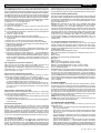
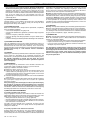
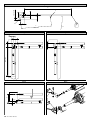
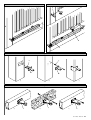
1
D811223 ver. 03 07-11-00
I
AUTOMAZIONI A PISTONE PER CANCELLI A BATTENTE
GB PISTON AUTOMATION FOR SWING GATES
F AUTOMATIONS A PISTON POUR PORTAILS BATTANTS
8 0 2 7 9 0 8 1 1 42 7 3
D KOLBEN AUTOMATIONEN FÜR FLÜGELGITTERTORE
E AUTOMATIZACIONES A PISTON PARA PORTONES CON BATIENTE
P AUTOMATIZAÇÃO A PISTÃO PARA PORTÕRS COM BATENTE
P7 - P 4.5
ISTRUZIONI D'USO E DI INSTALLAZIONE
INSTALLATION AND USER'S MANUAL
INSTRUCTIONS D'UTILISATION ET D'INSTALLATION
INSTALLATIONS-UND GEBRAUCHSANLEITUNG
INSTRUCCIONES DE USO Y DE INSTALACION
INSTRUÇÕES DE USO E DE INSTALAÇÃO
Via Lago di Vico, 44
36015 Schio (VI)
Tel.naz. 0445 696511
Tel.int. +39 0445 696533
Fax 0445 696522
Internet: www.bft.it
E-mail: [email protected]
P7 - P4.5 Ver. 03 - 1
ENGLISH
INSTALLATION MANUAL
Thank you for buying this product, our company is sure that you will be more
than satisfied with the product’s performance. The product is supplied with
a “Warnings” leaflet and an “Instruction booklet”. These should both be
read carefully as they provide important information about safety, installation,
operation and maintenance. This product complies with the recognised
technical standards and safety regulations. We declare that this product is
in conformity with the following European Directives: 89/336/EEC and 73/
23/EEC and 98/37/EEC and following amendments.
1) GENERAL SAFETY
WARNING! An incorrect installation or improper use of the product can
cause damage to persons, animals or property.
• The “Warnings” leaflet and the “Instruction booklet” supplied with this
product should be read carefully as they provide important information
about safety, installation, operation and maintenance.
• Scrap packing materials (plastic, cardboard, polystyrene etc) according
to the provisions set out by current standards. Keep nylon or polystyrene
bags out of children’s reach.
• Keep the instructions with the technical brochure for future reference.
• This product was exclusively designed and manufactured for the use
specified in the present documentation. Uses not specified in this
documentation could cause damage to the product and be dangerous.
• The Company declines all responsibility for any consequences resulting
from the product being used improperly or differently from whatever is
specified in the present documentation.
• Do not install the product in an explosive environment.
• The construction components of this product must comply with the
following European Directives: 89/336/CEE, 73/23/EEC, 98/37 and
following amendments. As for all non-EEC countries, the above
mentioned standards as well as the current national standards should
be respected in order to have a good safety level.
• The Company declines all responsibility for any consequences resulting
from failure to observe Good Technical Practice when constructing
closing structures (door, gates etc.), as well as from any deformation
which might occur during use.
• The installation must comply with the provisions set out by the following
European Directives: 89/336/CEE, 73/23/EEC, 98/37/EEC and following
amendments.
• Disconnect the electrical power supply before carrying out any operations
on the plant. Also disconnect any buffer batteries, if fitted.
• Fit an omnipolar circuit breaker or thermal magnetic circuit breaker on
the mains power supply, having a contact opening distance equal to or
greater than 3 mm.
• Check that a differential switch with a 0.03A threshold is fitted just before
the power supply mains.
• Check that earthing is carried out correctly: connect all metal parts for
closure (doors, gates etc.) and all system components provided, with an
earth terminal.
• Fit all the safety devices (photocells, electric edges etc.) which are
needed to protect the area from any danger caused by squashing,
conveying and shearing.
• Position at least one light signal device (blinker) where it can be easily
seen, and fix a Warning sign to the structure.
• The Company declines all responsibility with respect to the automation safety
and good operation when other manufacturers’ components are used.
• Only use original parts for any maintenance or repair operation.
• Do not modify the automation components, unless explicitly authorised
by the Company.
• Instruct the product user about the control systems provided and the
manual opening operation in case of emergency.
• Do not allow persons or children to remain in the automation operation area.
• Keep radio control or other control devices out of children’s reach, in
order to avoid unintentional automation activation.
• The user must avoid any attempt to carry out work or repair on the
automation system, but only request assistance from qualified personnel.
• Anything which is not expressly provided for in the present instructions,
is not allowed.
2) GENERAL OUTLINE
A compact sturdy hydraulic piston, available in various versions according
to the user’s requirements and type of operation. All models are supplied
without locks (reversible), and an electric lock is required to keep them
blocked. To make the manual manoeuvre easier, the lock can be released
by means of a knob which can be reached using the appropriate key.
The pushing force is adjusted with extreme precision by means of two bypass valves which provide antisquash safety. The end-of-stroke operation
is electronically set in the control panel by means of a timer.
All models are available with slow-down function during the closing phase.
12 - P7 - P4.5
Ver. 03
3) MAIN AUTOMATION PARTS (Fig.1)
M) 2-pole single-phase motor, protected by thermal circuit-breaker.
N) Hydraulic lobe pump.
O) Distributor with adjustment valves.
P) Cylinder with piston.
CS) Rod cover.
S) Tank.
SB) Release.
T) Head with slow-down adjustment valve.
U) Base with articulated joint.
Components supplied: Attachments for pillars and gate - personalised
release key - drive capacitor - instruction manual.
4) TECHNICAL SPECIFICATIONS
Mod. P7 - Mod. P4.5
Power supply ...................................................... 230Vac±10% - 50 Hz (*)
Motor ........................................................................................... 2800min-1
Absorbed power ............................................................................... 250W
Capacitor .............................................................................................. 8µF
Absorbed current ................................................................................. 1.1A
Max. pressure ............................................ 5MPa (50bar) - 4MPa (40bar)
Pump capacity ............................................................... 0.6l/min - 0.9l/min
Pushing force ..................................................................... 8000N - 6500N
Towing force ...................................................................... 6500N - 5200N
Opening time (working stroke) ................................................... 45s - 30s
Closing time (working stroke) ............ 42s+slow-down - s 28s+slow-down
Type of lock ............................................................................ Electric lock
Max leaf length ......................................................................... 7m - 4.5m
Max. leaf weight ................................................................ 5000N (~500kg)
Working stroke ................................................................................ 390mm
Slow-down stroke ............................................................................. 20mm
Mechanical slow-down .............................................................. On closing
Manoeuvres in 24 hours ...................................................................... 500
Impact reaction ................................................................. Hydraulic clutch
Manual manoeuvre ................................................................. Release key
Thermal protection ........................................................................... 160°C
Environmental conditions ................................................ -10°C ÷ / +60°C
Degree of protection ............................................................................ IP55
Controller weight .......................................................... 122.5N (~12.25kg)
Dimensions ................................................................................... See fig.2
Oil ....................................................................................... Idrolux (3 litres)
(*) (Special voltage on request).
5) ACTUATOR INSTALLATION
5.1) Preliminary checks
Check that:
• The gate structure is sufficiently sturdy. Also make sure that the actuator
pushes against the leaf reinforced section.
• The leaves move manually and without effort all along their stroke.
• The door stop plates are fitted at the end of both closing and
opening strokes.
• If the gate has not been recently installed, check the wear condition of
all components. Repair or replace faulty or worn parts.
The automation reliability and safety are directly influenced by the state
of the gate structure.
5.2) Installation dimensions
The installation dimensions can be worked out from the table concerning
the respective model (fig. 3) and with reference to the diagram in fig.4.
The diagram in fig. 4 uses the following conventional references:
P Rear bracket fixed to pillar.
F Leaf fixing front fork.
a-b Dimensions used to determine the fixing point for bracket “P”.
C Value of fixing distance between centres.
D Leaf length.
x Distance from the leaf axis to the pillar edge.
Z Value always greater than 50 mm (b - x).
kg Max leaf weight (see Technical specifications).
a° Leaf opening angle.
5.3) How to interpret the installation measurements (Fig.3)
The “a” and “b” values can be chosen from the table (fig. 3) depending on
the a° opening degrees which are to be obtained. The table highlights the
optimum “a” and “b” values for an opening of a°=90° at constant speed; in
this condition, the sum of the “a” and “b” values is equal to the value of the
working stroke “Cu” (fig.2).
If the “a” and “b” values used are too different, the leaf movement is not
constant, and the towing-pushing force and movement speed may vary
INSTALLATION MANUAL
during manoeuvring. Maximum “a” and “b” values develop maximum piston
force. Warning! All versions are provided with a ball joint which allows the
rod to be lengthened or shortened by approximately 5 mm, but only if it was
fixed using the dimensions shown in fig. 8 before installation; after installation,
this adjustment allows the rod stroke to be corrected. Fig.9 illustrates the
oscillation that the controllers may show with respect to their horizontal
axis. During installation, scrupulously follow all the phases described below,
taking care to protect the actuator’s chromium-plated rod at all times, in order
to prevent it from being damaged by impact or any welding slag.
1) Identify “a - b - a° ” in the table in fig.3.
2) Fix bracket “P” (fig.10) to the pillar.
3) Fit the piston in bracket “P”.
4) Slacken the slow-down screw (fig.21) using the 3mm Allen wrench
provided.
5) Pull the rod out completely after activating the emergency release (fig.18).
6) Push the rod back in manually by a maximum of 10 mm and tighten the
emergency release (fig.18).
7) Fit fork “F” (fig.8) to the rod.
8) Fully close the gate leaf against the centre stop plate.
9) Keeping the piston level, mark the position for attaching fork (fig.10 ref.
“F”) to the leaf.
10) Remove fork “F” from the rod and move the piston sideways.
11) Fix fork (fig.10 ref. “F”) to the leaf by means of screws or welding.
12) Reconnect the rod to fork “F” and supply the actuator with power to
adjust the slow-down function.
13) Activate the gate to open.
14) Completely close the slow-down screw by turning it towards the “+”sign
(fig.21) and activate the leaf closing operation. The leaf should stop
before arriving at the closing position.
15) Slacken the adjustment screw towards the “-” sign until obtaining a
slow-down speed which avoids unpleasant slamming noise. Keep in
mind that slowing down can only be obtained during closing, precisely
for the last 30mm of rod stroke, 10mm of which account for safety extrastroke; therefore, slowing down takes place during the last 20mm of
working stroke.
5.4) Suggestions for particular installations
Fig.5 A recess must be made to house the controller when the leaf is
completely open; the recess measurements are shown in fig. 5.
Fig.7 When the ”b” dimension is greater than the values shown in the
installation tables, it is necessary to move the leaf hinge-pivot or make a
recess in the pillar, as in fig.6.
5.5) Anchoring of attachments to the pillar
Weld or fix the bracket base supplied to the pillar, check the “a” and “b”
measurements and then weld plate “P” to the said base. (fig.10).
• If the pillar is made of masonry, plate “P” must be welded to the metal
base “PF” and deeply anchored by means of suitable hooks “Z” which
are to be welded on the back of the said base (fig. 11a).
• If the pillar is made of stone, plate “P” is welded to the metal base “PF”
and can be fixed by means of four metal screw anchors “T” (fig.11b);
if the gate is large, it is advisable to weld plate “P” to an angle-shaped
base (fig.11c).
5.6) Anchoring of attachments to the leaf
Weld or fix fork “F” to the leaf at distance between centres “C” shown in fig.
4, making sure that the actuator is perfectly level (level “L”, fig.10) with
respect to the gate movement plane.
• If the gate is made of metal, the fork can be welded (fig.12a) or fixed
using appropriate screws (fig.12c).
• If the gate is made of wood, the fork can be fixed using appropriate
screws (fig.12b).
6) Ground leaf stop plates
For the actuator to operate correctly, stop plates “FA” must be used during
both opening and closing manoeuvres, as shown in fig.13. The leaf stop
plates must prevent the actuator rod from going to the end-of- stroke
position. Fig. 14 specifies the dimensions needed to check the correct
actuator installation both for pushing and towing. The plates must be
positioned in such a way as to maintain a rod stroke margin of approximately
10mm; this is to avoid possible operation anomalies (suchas a lock-up).
7) ELECTRIC LOCK FITTING
This is needed on all models, as no hydraulic lock is provided either for
opening or closing manoeuvres. The EBP model electric lock (fig.15)
consists of a continuous service electromagnet being anchored to the
ground. This device remains energised throughout the actuator operation
time, and allows the catch to stay lifted when it reaches the closing position,
ENGLISH
without opposing any resistance; the catch will drop into position when the
gate has completed the closing cycle. The electric lock can also be used to
keep the block of the gate in case of actuator malfunction or current failure.
8) ELECTRICAL INSTALLATION SET-UP
Lay out the electrical installation (fig.16) with reference to the CEI 64-8 and
IEC 364 provisions, complying with the HD 384 and other national standards
in force for electrical installation. The mains power supply connections must
be kept totally separate from the service connections (photocells, electric
edges, control devices etc.).
Warning! For connection to the mains, use a multipolar cable having
minimum 3x1.5mm2 cross section and complying with the previously
mentioned regulations (e.g.: a H07 RN-F cable with 3x1.5mm2 section).
Connect the control and safety devices in compliance with the previously
mentioned electrical installation standards. Fig.16 shows the number of
connections and the cross section for power supply cables having a length
of approximately 100 metres; in case of longer cables, calculate the cross
section for the true automation load. When the auxiliary connections
exceed 50-metre lengths or go through critical disturbance areas, it is
recommended to decouple the control and safety devices by means of
suitable relays.
8.1) The main automation components are (Fig.16):
I Type-approved omnipolar circuit breaker with at least 3mm contact
opening, provided with protection against overloads and short circuits,
suitable for cutting out automation from the mains. Place, if not al ready
installed, a type-approved differential switch with a 0.03A threshold just before
the automation system.
Qr Control panel and incorporated receiver.
SPL Preheating board for operation with temperature lower than 5°C
(optional).
S Key selector.
AL Blinker with tuned antenna and RG58 cable.
M Actuator.
E Electric lock.
Fte Pair of external photocells (emitter section).
Fre Pair of external photocells (receiver section).
Fti Pair of internal photocells with CF posts (emitter section).
Fri Pair of internal photocells with CF posts (receiver section).
T 1-2-4 channel transmitter.
Important: Before electrically activating the actuator, remove bleed screw
“S” (fig. 17) which is positioned under the articulated joint block and keep
it for any later reuse. Only remove bleed screw “S” when the actuator is
installed. Fit the release cover block provided, as illustrated in the drawing
(fig.18). “Warning! For the connection of the accessories, please refer to
the relevant instruction manuals. The type of control boards and accessories
must be suitable for the intended use and in compliance with the current
safety standards”
9) MANUAL OPENING
In case of emergency, for example when the electrical power is disconnected, open the electric lock by means of the appropriate key to release
the gate, and open the leaf manually; you may also reach the release knob
to facilitate the manoeuvre. In order to get access to the release knob, move
the small cap in the direction indicated by the arrow (fig.18) to reveal the
lock, insert the key, turn it clockwise by 90° and lift the entire release cover
by pulling with the key. The knob must be allowed to turn as far as possible
in the direction indicated by the arrows.
OPEN to release: the gate can be opened manually with ease.
CLOSE to lock: turn the knob clockwise until it is completely locked, and
so restore the actuator electrical operation.
10) PUSHING FORCE ADJUSTMENT
For safety reasons, proceed as follows in order to get access to the
adjustment valves:
• Move the release cover block cap in the direction indicated by the arrow
(fig.19) to reveal the lock.
• Insert the key, turn it clockwise by 90° and lift the entire block by pulling
with the key. Unscrew the two fixing screws and remove the entire
release system.
• The pushing force is adjusted by two valves marked with the writing
“Close” and “Open” respectively, which are used to adjust the closing
and opening pushing force (fig.19).
Turn the valves towards the “+” sign to increase the force transmitted;
turn the valves towards the “-” sign to reduce the force. To achieve
proper antisquash safety, the pushing force must be slightly higher than
that needed to move the leaf during both closing and opening manoeuvres;
the strength, which is measured on the leaf edge, must never exceed the
P7 - P4.5 Ver. 03 - 13
ENGLISH
INSTALLATION MANUAL
limits set out by the current national standards. Under no circumstances
whatsoever must the by-pass valves be fully closed. Complete the
adjustments and restore the release system, taking care to refit the
packing rings and washers. The actuator is not provided with electrical
limit switches. Therefore the motors switch off at the end of the operation
time set by the control unit. The said operation time must last
approximately 2-3 seconds after the moment when the leaves meet the
ground stop plates.
11) COVERING ELEMENT POSITIONING
Covering element “C” for all models can become left or right-handed by
reversing the position of cap “T” (fig.22), taking care to keep the water
drainage channel always at the bottom.
12) AUTOMATION CHECK
Before the automation device finally becomes operational, scrupulously
check the following conditions:
• Check that all components are tightly fixed.
• Check that all control devices (photocells, pneumatic edge etc) operate
correctly.
• Check the emergency manoeuvre command.
• Check the opening and closing operations using the control devices
provided.
• Check the normal (or personalised) function control logic in the control unit.
13) AUTOMATION OPERATION
Since the automation system can be remotely controlled by means of a
radio control device or a Start button, all safety devices must be frequently
checked in order to ensure their perfect efficiency. In the event of any
irregular operation, request immediate assistance from qualified personnel.
Children must be kept at a safe distance from the automation
operation area.
14) CONTROL
Various types of control are provided (manual, radio control, magnetic card
access control etc.) depending on the installation requirements and
characteristics. (See the specific instructions for the various control systems).
The installer undertakes to instruct the user about the correct
automation operation, and also point out the operations required in
case of emergency.
15) MAINTENANCE
Before carrying out any maintenance to the controller, disconnect the
system power supply. Periodically check the system for oil leaks.
Topping up should be carried out as follows:
a) Remove the release system (see fig.19).
b) Keeping the gate closed, top up using the prescribed oil until its level
reaches above the piston pipe (fig.20 ref. ”P”). To check this, insert a
screwdriver through the release cover block fixing hole, so as to reach
the piston pipe and make sure it is oiled.
c) Refit all the component paying attention to the seals. Check all automation
safety devices.
When any operational malfunction if found, and not resolved, disconnect
the system power supply and request the assistance of a qualified
technician (installer).
If the power supply cable is damaged, it must be replaced directly by
our company or our technical service department or by a technician
having similar qualification so as to avoid any risks. When automation
is out of order, activate the manual release knob to allow the manual opening
and closing operations to be carried out by means of the electric lock.
16) MALFUNCTIONS AND REMEDIES
16.1) Faulty operation of the actuator
Using an appropriate instrument, check that the ends of the actuator are
supplied with voltage after the opening or closing command is given. If the
motor vibrates but does not turn, the causes could be as follows:
• Wrong connection of common wire C (always light blue).
• No connection between the drive capacitor and the two drive terminals.
• If the leaf movement is opposite to what it should be, reverse the motor
drive connections in the control unit.
Leaf stops: when the operation time is insufficient, the leaves may not
complete their strokes. In that case, slightly increase the operation time
setting in the control unit.
16.2) Faulty operation of the electrical accessories
All faulty control and safety devices can cause abnormal operation or
automation block. If the control unit is provided with a self-diagnosing
system, identify the fault. In case of malfunction, it is advisable to disconnect
14 - P7 - P4.5
Ver. 03
and bridge all the automation devices one by one, if necessary, until the
faulty device is identified. After replacing or repairing it, restore all the
devices which were previously disconnected or bridged. For all devices
installed, refer to their respective instruction manual.
Warning: the above operation must be carried out by qualified personnel.
During maintenance, the gate operational area must be appropriately
indicated and closed off, in order to avoid any danger to persons, animals
and property. Warnings: Correct controller operation is only guaranteed
when the data specified in this manual are respected. The company cannot
be held responsible for any damage caused by failure to observe the
standards on safety, installation and good technical practice, as well as the
directives specified in the present manual.
17) SCRAPPING
Warning: This operation should only be carried out by qualified personnel.
Materials must be disposed of in conformity with the current regulations.
In case of scrapping, the automation devices do not entail any particular
risks or danger. In case of recovered materials, these should be sorted out
by type (electrical components, copper, aluminium, plastic etc.).
18) DISMANTLING
Warning: This operation should only be carried out by qualified personnel.
When the automation system is disassembled to be reassembled on
another site, proceed as follows:
• Disconnect the power supply and the entire external electrical instal lation.
• Replace the bleed screw (fig.17) under the articulated joint block.
• In the case where some of the components cannot be removed or are
damaged, they must be replaced.
The descriptions and illustrations contained in the present manual
are not binding. The Company reserves the right to make any alterations
deemed appropriate for the technical, manufacturing and commercial
improvement of the product, while leaving the essential product
features unchanged, at any time and without undertaking to update
the present publication.
Fig. 1
F
S
CS
SB
M
P
D
C
T
90
119
Fig. 2
1418
1335
410 (Ct)
925
390 (Cu)
10
90
100
10
Ct = Corsa totale
Total stroke
Course totale
Totalhub
Carrera total
Curso total
Cu = Corsa utile
Working stroke
Course utile
Nutzhub
Carrera útil
Curso útil
20 (Cr)
Cr = Corsa rallentamento
Slow-down stroke
Course de ralentissement
Verlangsamungsstrecke
Carrera de deceleraciûn
Curso desaceleração
Fig. 3
a (mm)
120
135
150
165
180
195
210
225
240
255
270
117
109
103
99
95
92
92
285
b (mm)
120
135
123
111
104
99
95
150
114
105
99
95
92
123
107
100
95
91
91
165
109
100
95
118
101
95
90
90
180
195
103
95
106
95
89
95
89
210
225
240
255
95
270
88
285
88
α
P7 - P4.5 Ver. 03 - 27
Fig. 4
Z=b-x >50mm
D
b
x
F
P
a
kg
αϒ
C
Max. 1325
Fig. 5
Fig. 6
55
b
Min. 1400
b
a
Fig. 7
Fig. 8
-5
+5
b
b
F
28 - P7 - P4.5
Ver. 03
Fig. 9
Fig. 10
P
7ϒ
F
L
Fig. 11
T
Z
PF
PF
a)
b)
c)
Fig. 12
a)
F
F
b)
c)
F
P7 - P4.5 Ver. 03 - 29
Fig. 13
FA
FA
FA
Sx
Dx
Fig. 14
Close
x.
400
ma
10
400
Open
Fig. 15
Fig. 16
AL
S
Fre
M
2
3x1
m
1m
4x
mm 2
E
2
58
1
2x
Qr
SPL
RG
mm
2x1
Fti
.5m
2x1
Fte
CF
m2
mm 2
2x1
.5m
m2
2
1
m
.5m
4x
Fri
EBP
T
CF
30 - P7 - P4.5
Ver. 03
2
m
1m
4x
I
3x1
.5m
m2
Fig. 17
Fig. 18
OPE
N
C L O SE
S
Fig. 19
a)
CLOSE
b)
OPEN
c)
P7 - P4.5 Ver. 03 - 31
Fig. 20
P
Fig. 21
Fig. 22
C
T
BFT
FRANCE
Parc Club des Aygalades
35 bd capitaine GEZE
13333 MARSEILLE Cedex 14
Tel.
Fax
0491101860
0491101866
BFT
DEUTSCHLAND
Vertretung und Lager
Johannisstr. 14,D-90763 Fürth
Tel.
Fax
32 - P7 - P4.5
Ver. 03
0049 911 773323
0049 911 773324
BFT S.p.a.
ITALIA
Via Lago di Vico, 44
36015 Schio (VI)
Tel.naz. 0445 696511
Tel.int. +39 0445 696533
Fax 0445 696522
Internet: www.bft.it
E-mail: [email protected]