1
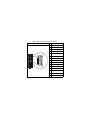
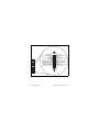
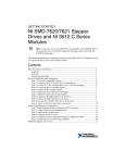
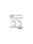
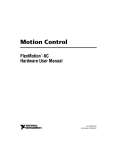
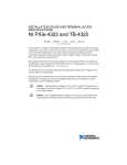
OPERATING INSTRUCTIONS AND SPECIFICATIONS NI 9514 Servo Drive Interface Module with Encoder Feedback Français Deutsch ni.com/manuals This document describes how to use the National Instruments 9514 module and includes specifications and pin assignments for the NI 9514. Visit ni.com/info and enter the Info Code rdsoftwareversion to determine which software you need for the modules you are using. For information about installing, configuring, and programming the system, refer to the system documentation. Visit ni.com/info and enter cseriesdoc for information about C Series documentation. Note The safety guidelines and specifications in this document are specific to the NI 9514. The other components in the system may not meet the same safety ratings and specifications. Refer to the documentation for each component in the system to determine the safety ratings and specifications for the entire system. NI 9514 Operating Instructions and Specifications 2 ni.com Safety Guidelines Operate the NI 9514 only as described in these operating instructions. This icon denotes that the component may be hot. Touching this component may result in bodily injury. Hot Surface Special Conditions for Marine Applications Some modules are Lloyd’s Register (LR) Type Approved for marine applications. To verify Lloyd’s Register certification, go to ni.com/certification and search for the LR certificate, or look for the Lloyd’s Register mark on the module. To meet radio frequency emission requirements for marine applications, use shielded cables and install the system in a metal enclosure. Suppression ferrites must be installed on power supply inputs near power entries to modules and controllers. Power supply and module cables must be separated on opposite sides of the enclosure and must enter and exit through opposing enclosure walls. Caution © National Instruments Corp. 3 NI 9514 Operating Instructions and Specifications Connecting the NI 9514 The NI 9514 servo drive interface module is part of a family of C Series motion modules. The module provides servo drive interface signals for a single axis, a full set of motion I/O including inputs for a home switch and limit switches, incremental encoder inputs for position feedback, and 0 to 30 V digital input lines. The NI 9514 also includes a processor to run the spline interpolation engine and PID control loop. Working together they produce smoother motion resulting in precise servo motion control. System Connection The NI 9514 has two connectors, a 15-pin DSUB drive interface connector and a 20-pin MDR feedback connector. The 15-pin DSUB includes command signals for interfacing with servo amplifiers or drives, a 0 to 30 V general-purpose digital input line, and a 19 to 30 V input for power connection. Refer to Table 1 for the DSUB connector pin assignments. The remainder of this document does not distinguish between drives and amplifiers. All references to drives also apply to amplifiers. Note NI 9514 Operating Instructions and Specifications 4 ni.com The 20-pin MDR connector includes incremental encoder feedback inputs, a +5 V output for encoder power, home, limit, and position compare inputs, an output for position compare, an additional 19 to 30 V input for power connection, and an additional 0 to 30 V general-purpose digital input line. Refer to Figure 2 for the MDR connector pin assignments. Note The NI 9514 requires an external power supply. You can connect the external power supply to the Vsup input provided on the DSUB or MDR connector. Do not connect more than one external power supply to the module. National Instruments offers several options for connecting the NI 9514 to servo drives. You can use the NI 951x Cable and Terminal Block Bundle to connect to third-party servo drives. Refer to Figure 3 for the 37-pin terminal block pin assignments. Refer to the NI 951x User Manual, which you can download from ni.com/manuals, for information about additional connection accessories and cabling recommendations. © National Instruments Corp. 5 NI 9514 Operating Instructions and Specifications Complete the following steps to connect the NI 9514 servo drive interface module to drives and other I/O: 1. Install the module in the chassis as specified in the chassis documentation. Note Refer to the NI SoftMotion Module book of the LabVIEW Help for information about chassis, slot, or software restrictions. 2. Connect the module to a 37-pin terminal block using the NI 951x Cable and Terminal Block Bundle, or use a custom cable for direct connectivity. 3. Connect the NI 9514 module to an external power supply. Caution Do not connect anything to pins marked Reserved. The 37-pin terminal block has separate Vsup and COM terminals for each connector. Make sure you are using the correct Vsup and COM terminals for the connector you are using. All signals associated with the DSUB connector in Figure 3 are marked with a dagger (†). Caution Figure 1 shows a simplified system connection diagram. NI 9514 Operating Instructions and Specifications 6 ni.com DSUB Connector Drive Command MDR Connector Encoder 0 Phase A, B, Index +5 V OUT Drive Enable Forward, Reverse Limit, Home Drive Fault Vsup NI 9514 Limit and Home Sensors NI Connection Accessory/ Custom Cable Power Supply Drive Command Drive Enable Drive Drive Fault Motor Servo Motor Encoder Figure 1. NI 9514 Connection Example © National Instruments Corp. 7 NI 9514 Operating Instructions and Specifications Table 1. NI 9514 DSUB Connector Pin Assignments Connector 15 11 10 6 NI 9514 Operating Instructions and Specifications 5 1 8 Pin Signal 1 Drive Command COM 2 Drive Enable 3 Reserved 4 Reserved 5 Reserved 6 Drive Command 7 COM 8 Digital Input 1 9 Reserved 10 Reserved 11 Reserved 12 Vsup 13 Reserved 14 COM 15 Reserved ni.com Reverse Limit Reserved Vsup Reserved COM Encoder 0 Phase A+ Encoder 0 Phase A– Encoder 0 Phase B+ Position Capture Encoder 0 Phase B– 11 12 13 14 15 16 17 18 19 20 1 2 3 4 5 6 7 8 9 10 Forward Limit Home COM Digital Input 0 COM Encoder 0 Index+ Encoder 0 Index– COM +5 V OUT Position Compare Figure 2. NI 9514 MDR Connector Pin Assignments © National Instruments Corp. 9 NI 9514 Operating Instructions and Specifications Position Capture 29 Encoder 0 Phase B– 30 Reserved 31 Drive Command COM† 32 COM† 33 Drive Enable† 34 Reserved 35 Reserved 36 Reserved 37 18 GND Encoder 0 Phase B+ 28 17 Shield Encoder 0 Phase A– 27 16 Reserved Encoder 0 Phase A+ 26 15 COM† COM 25 14 Reserved Reserved 24 13 Digital Input 1† Vsup 23 12 Vsup† Reserved 22 11 Drive Command† Reverse Limit 21 10 Reserved Reserved 20 9 Position Compare 19 +5V OUT Reserved † 8 COM 7 Encoder 0 Index– 6 Encoder 0 Index+ 5 COM 4 Digital Input 0 3 COM 2 Home 1 Forward Limit Reserved Indicates DSUB connector signals. Figure 3. NI 9514 37-Pin Terminal Block Pin Assignments NI 9514 Operating Instructions and Specifications 10 ni.com Signal Connections Figure 4 shows the NI 9514 block diagram. Phase A± (0) Receiver Circuitry Phase B± (0) Index± (0) Position Capture Buffer DAC Drive Command Buffer Position Compare Microprocessor (PID Loop) Drive Enable Home Output Circuitry Forward Reverse Vsup Input Circuitry COM Digital Input (0-1) +5V Reg +5V OUT Figure 4. NI 9514 Block Diagram © National Instruments Corp. 11 NI 9514 Operating Instructions and Specifications Note This document provides a brief overview of the module signal connections. Refer to the NI 951x User Manual, which you can download from ni.com/ manuals, for more information about signal connections. The NI 9514 module provides a ±10 V analog Drive Command output. Use the Drive Command COM signal instead of COM as a reference for the Drive Command Output. This reference signal helps keep digital noise separate from the analog output. The encoder channel consists of a Phase A, a Phase B, and an Index input. The NI 9514 supports RS-422 differential and single-ended inputs for Phase A, Phase B, and Index signals, and provides a +5 V output for encoder power. National Instruments strongly recommends you use encoders with differential line driver outputs for optimized noise immunity and improved accuracy in all applications. Figures 5 and 6 show simplified schematic diagrams of the encoder input circuit connected to differential and single-ended encoder outputs. NI 9514 Operating Instructions and Specifications 12 ni.com Encoder NI 9514 Phase + +5 V Receiver Phase – COM Figure 5. Differential Encoder Input Circuit Encoder +5 V NI 9514 Phase+ +5 V Receiver No Phase– Connection Com COM Figure 6. Single-Ended Encoder Input Circuit © National Instruments Corp. 13 NI 9514 Operating Instructions and Specifications You can configure the Forward Limit, Reverse Limit, and Digital Input <1..2> signals in software for sinking or sourcing output devices and set the active state of the inputs in software to on or off. To use the Drive Fault signal referenced in Figure 1, you can map an available digital input in software. Figure 7 shows an example of wiring the input signals to a sourcing output device. PNP (Sourcing) Output Device NI 9514 V+ Out Limit, Home, or Digital Input Limit, Home, Configured or Digital Input For Sinking V– (Reference) COM Figure 7. Limit or Digital Input Circuit Configured for Sinking NI 9514 Operating Instructions and Specifications 14 ni.com Figure 8 shows an example of wiring the input signals to a sinking output device. NPN (Sinking) Output Device NI 9514 NI 9514 Vsup V+ Limit, Home, Configured or Digital Input For Sourcing Out Limit, Home, or Digital Input V– (Reference) COM Figure 8. Limit or Digital Input Circuit Configured for Sourcing The NI 9514 Drive Enable signal is software configurable for sinking or sourcing output type and the active state is software configurable for on or off. © National Instruments Corp. 15 NI 9514 Operating Instructions and Specifications Only connect the Drive Enable output to +5 V input circuitry when the output is configured for sinking. Caution Figure 9 shows an example of wiring the output signals to a sinking input device. NPN (Sinking) Input Device NI 9514 V+ NI 9514 Vsup Drive Enable Drive Enable Configured For Sourcing In Sinking Circuit COM V– (Reference) Figure 9. Drive Enable Output Circuit Configured for Sourcing NI 9514 Operating Instructions and Specifications 16 ni.com Figure 10 shows an example of wiring the output signals to a sourcing input device. PNP (Sourcing) Input Device NI 9514 V+ NI 9514 Vsup Drive Enable Sourcing Circuit In Drive Enable Configured For Sinking V– COM (Reference) Figure 10. Drive Enable Output Circuit Configured for Sinking © National Instruments Corp. 17 NI 9514 Operating Instructions and Specifications LED Indicators The NI 9514 has four LEDs to display status information. 1 1 Axis Status (Green) 2 Encoder Active (Green) 2 3 4 3 Limit Active (Yellow) 4 Axis Fault (Red) Axis Status The Axis Status LED (green) has three states to display axis status. • Off—The module is in sleep mode or failed to boot correctly. Refer to the NI SoftMotion Module book of the LabVIEW Help for troubleshooting information. • Flashing—The module booted up correctly and is functional. • Lit—The module is functional and the drive enable output is active. NI 9514 Operating Instructions and Specifications 18 ni.com Encoder Active The Encoder Active LED (green) has three states for encoder and Vsup status. • Off—The required power supply (Vsup) is not connected. You must connect a power supply to receive encoder pulses. • Flashing—The power supply (Vsup) is connected and the module is receiving encoder pulses. Note The LED flash rate does not correspond to the rate at which the NI 9514 receives encoder pulses. • Lit—The power supply (Vsup) is connected but the module is not receiving encoder pulses. Limit Active The Limit Active LED (yellow) has two states to display the status of the limits and home input. • Off—The power supply (Vsup) is not connected, or both the limits and home input are not active. • Lit—The power supply (Vsup) is connected and the forward limit, reverse limit, or home input is active. © National Instruments Corp. 19 NI 9514 Operating Instructions and Specifications Axis Fault The Axis Fault LED (red) has two states to indicate the presence of a fault in the system. Refer to the NI SoftMotion Module book of the LabVIEW Help for a list of module faults and troubleshooting information. • Off—No module faults. • Lit—One or more module faults. Sleep Mode This module supports a low-power sleep mode. Support for sleep mode at the system level depends on the chassis that the module is plugged into. Refer to the chassis manual for information about support for sleep mode. If the chassis supports sleep mode, refer to the software help for information about enabling sleep mode. Visit ni.com/info and enter cseriesdoc for information about C Series documentation. Typically, when a system is in sleep mode, you cannot communicate with the modules. In sleep mode, the system consumes minimal power and may dissipate less heat than it does in normal mode. Refer to the Specifications section for more information about power consumption and thermal dissipation. NI 9514 Operating Instructions and Specifications 20 ni.com Specifications The following specifications are typical for the range –40 to 70 °C unless otherwise noted. All voltages are relative to COM unless otherwise noted. Servo Performance Module modes of operation .............. Position loop and torque loop Control loop rate1.............................. 20 kHz max (position loop) Servo control loop modes ................. PID, PIVff, and Dual-Loop Motion Command Signals Servo command analog outputs Voltage range.............................. ±10 V, relative to Drive Command COM Resolution................................... 16 bits (0.000305 V/LSB), monotonic Max output current ..................... ±2 mA 1 When using a torque loop, the control loop rate depends on the processor speed and communication bus bandwidth. Refer to the NI SoftMotion Module book of the LabVIEW Help for more information. © National Instruments Corp. 21 NI 9514 Operating Instructions and Specifications Drive enable output Output type................................. Programmable: sinking or sourcing Voltage range.............................. 0 to 30 V Vsup input.................................... 19 to 30 V Continuous output current (I0) on each channel .......................... ±100 mA max Output impedance (R0) ............... 0.3 Ω max Output voltage (V0) sourcing...... Vsup – (I0R0) Output voltage (V0) sinking........ I0R0 Min output pulse width .............. 100 µs Active state ................................. Programmable: on or off Motion I/O Encoder 0 Phase A/B and Index inputs Type ............................................ RS-422 differential or single-ended inputs Digital logic levels, single-ended Voltage ................................. –0.25 to 5.25 V High, VIH.............................. 2.0 V min Low, VIL ............................... 0.8 V max NI 9514 Operating Instructions and Specifications 22 ni.com Digital logic levels, differential (Phase(+) – Phase(–)) Input high range ................... 300 mV to 5 V Input low range .................... –300 mV to –5 V Common-mode voltage1 ...... –7 to 12 V Input current at 5 V .................... ±1 mA Min pulse width2 Differential ........................... 100 ns Single-ended ........................ 400 ns Max count rate Differential ........................... 20 × 106 counts/sec Single-ended ........................ 5 × 10⁶ counts/sec Forward, reverse, and home inputs Input type.................................... Programmable: sinking or sourcing Digital logic levels, OFF state Input voltage ........................ ≤ 5 V Input current......................... ≤ 250 µA 1 Common-mode voltage is the average of Phase+ and Phase–. 2 Assumes the minimum filter setting. Refer to the NI SoftMotion Module book of the LabVIEW Help for more information about filter options. © National Instruments Corp. 23 NI 9514 Operating Instructions and Specifications Digital logic levels, ON state Input voltage ........................ 11 to 30 V Input current......................... ≥ 2 mA Input impedance ......................... 30 kΩ ± 5% Min pulse width1 ........................ 100 µs Position capture input Digital logic levels Voltage ................................. –0.25 to 5.25 V High, VIH.............................. 2.0 V min Low, VIL ............................... 0.8 V max Input current (0 V ≤ Vin ≤ 4.5 V) ..................... ±2 mA max Min pulse width1 ........................ 100 ns Max capture latency ................... 200 ns Capture accuracy ........................ ±1 count Active edge................................. Programmable: rising edge or falling edge 1 Assumes the minimum filter setting. Refer to the NI SoftMotion Module book of the LabVIEW Help for more information about filter options. NI 9514 Operating Instructions and Specifications 24 ni.com Position compare outputs High, VOH ................................... 5.25 V max Sourcing 12 mA ................... 3.7 V min Sourcing 4 mA ..................... 3.9 V min Low, VOL Sinking 12 mA ..................... 0.7 V max Sinking 4 mA ....................... 0.5 V max Compare mode ........................... Programmable: single or periodic Compare action .......................... Programmable: set, toggle, or pulse Max compare rate (periodic) ...... 5 MHz Pulse width (programmable) Min....................................... 100 ns Max ...................................... 1.6 ms Active state ................................. Programmable: high or low © National Instruments Corp. 25 NI 9514 Operating Instructions and Specifications Digital Inputs Number of inputs .............................. 2 Input type .......................................... Programmable: sinking or sourcing Digital logic levels, OFF state Input voltage............................... ≤ 5 V Input current ............................... ≤ 250 µA Digital logic levels, ON state Input voltage............................... 11 to 30 V Input current ............................... ≥ 2 mA Input impedance................................ 30 kΩ ± 5% Min pulse width1 ............................... 50 µs MTBF ............................................... Contact NI for Bellcore MTBF or MIL-HDBK-217F specifications. 1 Assumes the minimum filter setting. Refer to the NI SoftMotion Module book of the LabVIEW Help for more information about filter options. NI 9514 Operating Instructions and Specifications 26 ni.com Power Requirements Power consumption from chassis Active mode ............................... 900 mW max Sleep mode ................................. 0.4 mW max Thermal dissipation (at 70 °C) Active mode ............................... 1.5 W max Sleep mode ................................. 0.4 mW max Vsup input .......................................... 19 to 30 V, 150 mA max +5 V regulated output ....................... 5 V ±5%, 150 mA max Physical Characteristics If you need to clean the module, wipe it with a dry towel. Note For two-dimensional drawings and three-dimensional models of the C Series module and connectors, visit ni.com/dimensions and search by module number. Weight............................................... 155 g (5.5 oz) © National Instruments Corp. 27 NI 9514 Operating Instructions and Specifications Safety Safety Voltages Connect only voltages that are within the following limits. Channel-to-COM .............................. 0 to +30 VDC max, Measurement Category I Isolation Channel-to-channel .................... None Channel-to-earth ground Continuous ........................... 60 VDC, Measurement Category I Withstand ............................. 500 Vrms, verified by a 5 s dielectric withstand test Measurement Category I is for measurements performed on circuits not directly connected to the electrical distribution system referred to as MAINS voltage. MAINS is a hazardous live electrical supply system that powers equipment. This category is for measurements of voltages from specially protected secondary circuits. Such voltage measurements include signal levels, special equipment, limited-energy parts of equipment, circuits powered by regulated low-voltage sources, and electronics. NI 9514 Operating Instructions and Specifications 28 ni.com Do not connect the NI 9514 to signals or use for measurements within Measurement Categories II, III, or IV. Caution Safety Standards This product meets the requirements of the following standards of safety for electrical equipment for measurement, control, and laboratory use: • IEC 61010-1, EN 61010-1 • UL 61010-1, CSA 61010-1 Note For UL and other safety certifications, refer to the product label or the Online Product Certification section. Electromagnetic Compatibility This product meets the requirements of the following EMC standards for electrical equipment for measurement, control, and laboratory use: • EN 61326 (IEC 61326): Class A emissions; Industrial immunity • EN 55011 (CISPR 11): Group 1, Class A emissions • AS/NZS CISPR 11: Group 1, Class A emissions © National Instruments Corp. 29 NI 9514 Operating Instructions and Specifications • FCC 47 CFR Part 15B: Class A emissions • ICES-001: Class A emissions Note For the standards applied to assess the EMC of this product, refer to the Online Product Certification section. Note For EMC compliance, operate this device with double-shielded cables. CE Compliance This product meets the essential requirements of applicable European Directives as follows: • 2006/95/EC; Low-Voltage Directive (safety) • 2004/108/EC; Electromagnetic Compatibility Directive (EMC) Online Product Certification Refer to the product Declaration of Conformity (DoC) for additional regulatory compliance information. To obtain product certifications and the DoC for this product, visit ni.com/ certification, search by module number or product line, and click the appropriate link in the Certification column. NI 9514 Operating Instructions and Specifications 30 ni.com Shock and Vibration To meet these specifications, you must panel mount the system. Operating vibration Random (IEC 60068-2-64)......... 5 grms, 10 to 500 Hz Sinusoidal (IEC 60068-2-6) ....... 5 g, 10 to 500 Hz Operating shock (IEC 60068-2-27).............................. 30 g, 11 ms half sine, 50 g, 3 ms half sine, 18 shocks at 6 orientations Environmental National Instruments C Series modules are intended for indoor use only, but may be used outdoors if installed in a suitable enclosure. Refer to the manual for the chassis you are using for more information about meeting these specifications. Operating temperature (IEC 60068-2-1, IEC 60068-2-2) ..... –40 to 70 °C Storage temperature (IEC 60068-2-1, IEC 60068-2-2) ..... –40 to 85 °C Ingress protection.............................. IP 40 © National Instruments Corp. 31 NI 9514 Operating Instructions and Specifications Operating humidity (IEC 60068-2-56).............................. 10 to 90% RH, noncondensing Storage humidity (IEC 60068-2-56).............................. 5 to 95% RH, noncondensing Max altitude ...................................... 2,000 m Pollution Degree (IEC 60664) .......... 2 Environmental Management National Instruments is committed to designing and manufacturing products in an environmentally responsible manner. NI recognizes that eliminating certain hazardous substances from our products is beneficial to the environment and to NI customers. For additional environmental information, refer to the NI and the Environment Web page at ni.com/environment. This page contains the environmental regulations and directives with which NI complies, as well as other environmental information not included in this document. NI 9514 Operating Instructions and Specifications 32 ni.com Waste Electrical and Electronic Equipment (WEEE) EU Customers At the end of their life cycle, all products must be sent to a WEEE recycling center. For more information about WEEE recycling centers and National Instruments WEEE initiatives, visit ni.com/ environment/weee.htm. ⬉ᄤֵᙃѻક∵ᶧࠊㅵ⧚ࡲ⊩ ˄Ё RoHS˅ Ёᅶ᠋ National Instruments ヺড়Ё⬉ᄤֵᙃ ѻકЁ䰤ࠊՓ⫼ᶤѯ᳝ᆇ⠽䋼ᣛҸ (RoHS)DŽ݇Ѣ National Instruments Ё RoHS ড়㾘ᗻֵᙃˈ䇋ⱏᔩ ni.com/environment/rohs_chinaDŽ (For information about China RoHS compliance, go to ni.com/ environment/rohs_china.) © National Instruments Corp. 33 NI 9514 Operating Instructions and Specifications Where to Go for Support The National Instruments Web site is your complete resource for technical support. At ni.com/support you have access to everything from troubleshooting and application development self-help resources to email and phone assistance from NI Application Engineers. National Instruments corporate headquarters is located at 11500 North Mopac Expressway, Austin, Texas, 78759-3504. National Instruments also has offices located around the world to help address your support needs. For telephone support in the United States, create your service request at ni.com/support and follow the calling instructions or dial 512 795 8248. For telephone support outside the United States, contact your local branch office: Australia 1800 300 800, Austria 43 662 457990-0, Belgium 32 (0) 2 757 0020, Brazil 55 11 3262 3599, Canada 800 433 3488, China 86 21 5050 9800, Czech Republic 420 224 235 774, Denmark 45 45 76 26 00, Finland 358 (0) 9 725 72511, France 01 57 66 24 24, Germany 49 89 7413130, India 91 80 41190000, Israel 972 3 6393737, Italy 39 02 41309277, Japan 0120-527196, NI 9514 Operating Instructions and Specifications 34 ni.com Korea 82 02 3451 3400, Lebanon 961 (0) 1 33 28 28, Malaysia 1800 887710, Mexico 01 800 010 0793, Netherlands 31 (0) 348 433 466, New Zealand 0800 553 322, Norway 47 (0) 66 90 76 60, Poland 48 22 328 90 10, Portugal 351 210 311 210, Russia 7 495 783 6851, Singapore 1800 226 5886, Slovenia 386 3 425 42 00, South Africa 27 0 11 805 8197, Spain 34 91 640 0085, Sweden 46 (0) 8 587 895 00, Switzerland 41 56 2005151, Taiwan 886 02 2377 2222, Thailand 662 278 6777, Turkey 90 212 279 3031, United Kingdom 44 (0) 1635 523545 © National Instruments Corp. 35 NI 9514 Operating Instructions and Specifications National Instruments, NI, ni.com, and LabVIEW are trademarks of National Instruments Corporation. Refer to the Terms of Use section on ni.com/legal for more information about National Instruments trademarks. Other product and company names mentioned herein are trademarks or trade names of their respective companies. For patents covering National Instruments products/technology, refer to the appropriate location: Help»Patents in your software, the patents.txt file on your media, or the National Instruments Patent Notice at ni.com/patents. © 2009 National Instruments Corp. All rights reserved. 374988B-01 Jul09