1
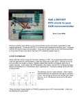
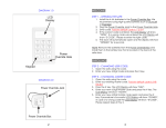
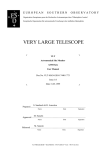
All Mikroelektronika’s development systems feature a large number of peripheral
modules expanding microcontroller’s range of application and making the
process of program testing easier. In addition to these modules, it is also
possible to use numerous additional modules linked to the development system
through the I/O port connectors. Some of these additional modules can operate
as stand-alone devices without being connected to the microcontroller.
Manual
Additional Board
RTC2
™
MikroElektronika
RTC2
RTC2 (Real time clock)
The real time clock enables the microcontroller to keep the real time and date including corrections for a leap year and months that
have less than 31 days. It has an alarm function, featuring automatic power-fail detection. It is used to generate an interrupt and square
wave output signal. Due to baterry cell the real time clock enables the microcontroller to keep the real time when the power supply
is off. The real time clock is linked to the development system by connecting 2x5 female connector provided on the additional board
to the 2x5 male connector provided on the development system’s I/O port. The RTC2 communicates to the microcontroller by using
the serial I2C interface. The RTC2 is placed on the development system’s port that is connected to the built-in I2C microcontroller
module.
Figure 1: RTC2
Figure 2: RTC2 placed on the development system
SMD jumpers are used for selecting the development system to place the
additional board on. When setting SMD jumpers to PIC position (default
position), the additional board can be connected to the development
system supporting PIC microcontrollers. When setting SMD jumpers to
AVR position, the additional board can be connected to the development
system supporting AVR microcontrollers. In order to set SMD jumpers to
AVR position, they should be resoldered, thus connecting middle contacts
and AVR contacts.
2x5 female connector is used for connecting the
additional board to the development system
Figure 3: RTC2’s back side
The DS1307 circuit pins are used for connecting to
the microcontroller. Their functions are as follows:
SQW
SCL
SDA
- Pin used to generate an interrupt or square wave output signal
- Serial clock line
- Serial data line
2x5 CN1 female connector pins’ funtions:
RC3
- SCL pin (jumpers are set to PIC position)
RC4
- SDA pin (jumpers are set to PIC position)
PC0
- SCL pin (jumpers are set to AVR position)
PC1
- SDA pin (jumpers are set to AVR position)
SQW/OUT - Pin used to generate an interrupt or square wave output signal
Figure 4: RTC2 connection schematic
MikroElektronika