1
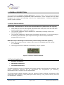
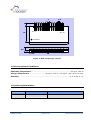
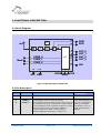
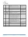
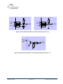
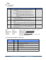
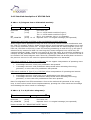
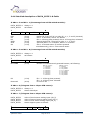
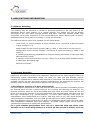
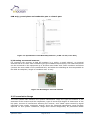
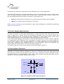
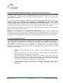
RF Receiver Module
RCM 130 step code DB
User Manual V1.32
May 2007
Revision History
The following major modifications and improvements have been made to the initial version of
the document (RCM 130 User Manual V1.0):
Version Subject (major changes since last version)
V1.0
V1.1
V1.2
V1.21
V1.22
V1.30
V1.31
V1.32
First version for RCM 130
Current consumption and voltage range modified
Titel of fig. 7 corrected; header information in 2.4.3 clarified
Updated declaration of conformity
Power supply application note updated
Firmware modification on serial interface
Antenna drawing corrected
Editorial corrections
Published by EnOcean GmbH, Kolpingring 18a, 82041 Oberhaching, Germany
www.enocean.com, [email protected], phone ++49 (89) 6734 6890
© EnOcean GmbH, All Rights Reserved
Important!
This information describes the type of component and shall not be considered as assured characteristics. No
responsibility is assumed for possible omissions or inaccuracies. Circuitry and specifications are subject to change
without notice. For the latest product specifications, refer to the EnOcean website: http://www.enocean.com.
As far as patents or other rights of third parties are concerned, liability is only assumed for modules, not for the
described applications, processes and circuits.
EnOcean does not assume responsibility for use of modules described and limits its liability to the replacement of
modules determined to be defective due to workmanship. Devices or systems containing RF components must meet
the essential requirements of the local legal authorities.
The modules must not be used in any relation with equipment that supports, directly or indirectly, human health or life
or with applications that can result in danger for people, animals or real value.
Components of the modules are considered and should be disposed of as hazardous waste. Local government
regulations are to be observed.
Packing: Please use the recycling operators known to you. By agreement we will take packing material back if it is
sorted. You must bear the costs of transport. For packing material that is returned to us unsorted or that we are not
obliged to accept, we shall have to invoice you for any costs incurred.
©EnOcean GmbH
Page 2 of 27
RCM 130 User Manual V1.32
Table of Contents
1. GENERAL DESCRIPTION________________________________________________________________ 4
1.1 Basic Functionalities ________________________________________________________________ 4
1.2 Typical Applications _________________________________________________________________ 4
1.3 Features Overview __________________________________________________________________ 5
1.4 Physical Dimensions ________________________________________________________________ 5
1.5 Environmental Conditions __________________________________________________________ 6
1.6 Ordering Information _______________________________________________________________ 6
2. FUNCTIONAL DESCRIPTION ___________________________________________________________ 7
2.1 Block Diagram _______________________________________________________________________ 7
2.2 Pin Description ______________________________________________________________________ 7
2.3 RCM 130 Operating Modes_________________________________________________________ 10
2.4 RCM 130 Serial Interface (Operating Mode 0 and 3)_____________________________ 12
2.5 Learning Modes ____________________________________________________________________ 17
2.6 Learning of Radio Transmitters ___________________________________________________ 18
2.7 Deleting Radio Transmitters_______________________________________________________ 20
2.8 Received Signal Strength Indicator (RSSI) _______________________________________ 21
2.9 Demodulated Direct Signal Output (RxD) ________________________________________ 21
3. APPLICATIONS INFORMATION _______________________________________________________ 22
3.1 Module Mounting ___________________________________________________________________ 22
3.2 Antenna Mounting__________________________________________________________________ 22
3.3 Transmission Range _______________________________________________________________ 23
3.4 Power Supply Requirements ______________________________________________________ 24
3.5 LMI Output Connection ____________________________________________________________ 24
3.6 Notes to RCM 130 Mode 0 and 3 (Serial Data Communication) _________________ 25
3.7 Approval Requirements ____________________________________________________________ 25
4. DEVELOPMENT TOOLS _________________________________________________________________ 26
4.1 Evaluation Kit EVA 100 ____________________________________________________________ 26
4.2 On-Board Overview EVA-PCB ______________________________________________________ 26
4.3 EVA 100 Scope of Supply and Ordering Information _____________________________ 26
5. DECLARATION OF CONFORMITY ______________________________________________________ 27
©EnOcean GmbH
Page 3 of 27
RCM 130 User Manual V1.32
1. GENERAL DESCRIPTION
The multifunctional receiver module RCM 130 is used to receive and to process telegrams
generated and transmitted by EnOcean radio transmitters. These modules can be easily
integrated into control and switching units for the implementation of different applicationspecific system solutions.
1.1 Basic Functionalities
Serial Data Communication via Receiver Module RCM 130 (all EnOcean RF signals):
•
Serial data link from all radio signals transmitted from PTM, STM, TCM and CTM radio
modules (9600 bps, 1 start bit, 1 stop bit)
•
This interface enables a simple realization of a Gateway to existing control and
monitoring systems
•
This interface enables any desired actor functionality by the user, e.g. by connecting to
a following microcontroller (the output control logic can be easily and flexible
programmed by the user)
RCM 130 output switching functionalities (controlled by PTM radio signals):
•
Basic signal output function “tubular motor control” (UP/DOWN with slat acting):
1 or 2 channel
•
Learning procedure for EnOcean transmitters, easy to operate
Figure 1: Receiver modules RCM 130
1.2 Typical Applications
•
Building installation
•
Industrial automation
•
Consumer Electronics
The RCM modules are part of a powerful RF system solution from EnOcean for operation and
control applications. Because the RF transmitters are self-powered (no batteries),
maintenance-free RF systems can be implemented.
The RCM modules operate together with the following further EnOcean components: PTM
(batteryless radio switches), STM (batteryless radio sensors), CTM (remote control) and TCM
(bi-directional IT interface)
©EnOcean GmbH
Page 4 of 27
RCM 130 User Manual V1.32
1.3 Features Overview
Power Supply: ........................................................................................ 5 V DC ± 5 %
Current Input: ............................................................ 29 mA max. (without output load)
Receive Frequency: ................................................ 868.3 MHz (stabilized by crystal PLL)
Sensitivity / Channel Bandwidth: ..................................................... -95 dBm / 280 kHz
Control Inputs: ................................... 6 inputs for set up of operating and learning modes
Functional Outputs: ......... 4 outputs, their function depends on the selected operation mode
Learning Mode Output: ................................................ indicates learning of transmitters
Number of RF transmitters learnable: ............................. up to 30 EnOcean transmitters
RSSI Output:.........................................................indicates received peak signal strength
Direct Signal Output: .................................................. physical layer 1 output (120 kbps)
1.4 Physical Dimensions
Antenna:............................................................................. 9 cm whip antenna mounted
Dimensions of PCB: ........................................18.0 x 42.0 x 5.5 mm (without wiring pins)
Connector: ........................................16 pins, grid 2.0 mm (4.0 mm in length,
©EnOcean GmbH
Page 5 of 27
0.5 mm)
RCM 130 User Manual V1.32
2
0.5
4
Pin 1
18
Pin 16
Antenna
42
Pin 1
5.5
2.45
Pin 16
30
1.225
Figure 2: RCM 130 package outlines
1.5 Environmental Conditions
Operating Temperature:..................................................................... -25 up to +65 °C
Storage Temperature: ........................... -40 up to +85 °C, +85 up to +100 °C for 1h max.
Humidity:............................................................................................ 0 % to 95 % r.h.
1.6 Ordering Information
Type
EnOcean Ordering Code
Remarks
RCM 130
S3002-B130
Serial Interface or Tubular Motor
©EnOcean GmbH
Page 6 of 27
RCM 130 User Manual V1.32
2. FUNCTIONAL DESCRIPTION
2.1 Block Diagram
14
RSSI
RXD
13
Ant
8
OUT_0
OUT_1
OUT_2
OUT_3
9
CODE_0
CODE_1
CODE_2
2
3
Mode
4
15
10
µC
11
12
1, 16
5
LRN
VCC GND
6
SSLM
LMI
7
CLR
Figure 3: Block diagram of RCM 130
2.2 Pin Description
Pin No.
Symbol
Function
1
GND_0
Ground connection
2
3
4
CODE_0
CODE_1
CODE_2
©EnOcean GmbH
Operational
characteristics
Encoding input for operation mode selection
(configuration of the receiver firmware).
The operation mode is defined at the first power-up
in accordance to the pin connecting. A later change
of the operation mode is possible at power-up, but
only if the ID memory is cleared in addition
(connect CLR-pin to GND -> power-down ->
change CODE-pin connecting -> power-up).
Page 7 of 27
Resistor network input.
Code pins should be left
open or connected to
GND (for encoding
schematics, see 2.3
RCM 130 Operating
Modes).
RCM 130 User Manual V1.32
5
LRN
6
SSLM
7
CLR
Control input to clear the receiver ID and scene
memory (all learned switch rockers, sensors and
scene switches)
Resistor network input:
Connect the open CLR
pin to GND for longer
than 2 seconds.
8
9
10
11
OUT_0
OUT_1
OUT_2
OUT_3
Functional control outputs (see 2.3 RCM 130
Operating Modes). Also indicate current learning
mode status (see 2.6 Learning of Radio
Transmitters).
Open collector outputs.
35 V max., 100 mA
max., 100 mW max.
each.
12
LMI
Learning Mode Indication output: LMI is Active High
in the learning mode phase. For optical indication,
LEDs can be connected with one lead directly to the
functional control outputs. The other lead of the
LEDs can be connected to the LMI pin in common,
so Learning Mode LEDs are switched off in
operation mode. If desired, the LMI pin can also be
used to switch off loads within learning mode (in
addition see Application Note chapter 3.5).
5 V TTL output, 20 mA
max.
13
RXD
Digital direct output of all received radio bit
streams (physical layer 1, 120 kbps).
Note: RCM 130 in Operating Mode 0 and 3 offers a
9.6 kbps standardized serial data output at OUT_0
(see chapter 2.4) which is very good suited for a
further data processing by the user.
5 V TTL output,
source impedance
11 KΩ
14
RSSI
Indication output of received signal strength (peak
detection)
Source impedance app.
20 KΩ
15
VCC
Power supply
5 V DC ± 5%, 29 mA
max. (without LMI
output current)
16
GND_1
©EnOcean GmbH
Control input to enter and to stop transmitter
learning mode: see 2.6 Learning of Radio
Transmitters.
During transmitter learning mode, the sensitivity of
the receiver is reduced to in-room operation.
Resistor network input:
Connect the open LRN
pin to GND for longer
than 0.5 sec.
not used in RCM130
Ground connection
Page 8 of 27
RCM 130 User Manual V1.32
VCC
VCC
10K
10K
CODE_2
8K2
CODE_1
10K
CODE_0
22K
ADC
(internal
(Mode)
CLR
8K2
SSLM
10K
LRN
22K
100n
ADC
(internal)
(Mode)
100n
Figure 4: Equivalent schematics of Control Inputs (pins 2 to 7)
OUT_x
external
OC
(external
(OC) )
4K7
OUT_x
internal
TTL
(TTL) )
(internal
22K
Figure 5: Equivalent schematics of Functional Outputs (pins 8 to 11)
©EnOcean GmbH
Page 9 of 27
RCM 130 User Manual V1.32
2.3 RCM 130 Operating Modes
The following operating modes can be configured by the encoding inputs CODE_2..0 of the
RCM 130 module:
Mode
Function
Output signal description
0
Serial
Interface
OUT_0: Asynchronous Interface,
supplies standard data blocks of
information from all received EnOcean
radio telegrams (9600 bps; 8 data
bits, no parity bit, one start bit, one
stop bit). For further information see
chapter 2.4
OUT_1: Learning mode status
indicator
1
2
None
Tubular Motor
Control
- 2 channel
3
Serial
Interface
4
5
None
None
6
Tubular Motor
Control
- 1 channel
7
Test
Same as Mode 6 but operation of 2
receiver channels:
channel 1 at OUT_0 and OUT_1
channel 2 at OUT_2 and OUT_3
Same as Mode 0 but:
learning of 1BS and 4BS
transmitters without learn bit
deletion of IDs only via CLR
Control signals
- “Open/Up” at OUT_0 and
- “Close/Dn” at OUT_1
with slat acting function (rocker
pushed not longer than Ts ~ 0.75
sec.).
Continuous shutter running for 2
min is started when the rocker is
pushed longer than Ts sec.
Switchover time at changing
the driving direction is Ts ~ 0.75 sec.
Reserved (module test mode)
-
No. of
channels
1
(OUT_0..1)
2
(OUT 0-1,
OUT 2-3)
1
(OUT 0-1)
CODE
_2
CODE
_1
CODE
_0
NC
NC
NC
NC
NC
NC
GND
GND
NC
NC
GND
GND
GND
GND
NC
NC
NC
GND
GND
GND
NC
GND
GND
GND
The operation mode is defined with pin status at power-up; a change of operation mode is
possible with cleared ID memory only.
Note: Since RCM 130 operating modes 2 and 6 are switching functions, transmitter
modules with switching functionality can be learned in these modes only (RPS and
HRC radio telegrams from PTM, CTM or TCM modules).
Note: Mode 0 and 3 (Serial Interface) provides an optional to use, simple teach-in
functionality for PTM, STM, CTM and TCM modules:
©EnOcean GmbH
Page 10 of 27
RCM 130 User Manual V1.32
While the receiver is in learn phase the IDs of all arriving transmitter telegrams are stored.
Only EnOcean telegrams from previously learned transmitters are output at the serial
interface. An additional bit (see H_SEQ at chapter 2.4) marks them as known, new (just
learned) or just deleted.
If no IDs have been stored the RCM 130 outputs all received EnOcean telegrams at the serial
interface. In H_SEC they are marked as unknown.
Tubular Motor Control
(MODE 6):
Ts
OUT_1
(Close/Dn,
Ts ~ 0.75s)
Start of continuous
running for ~ 2 min
Slat action
Premature stop of
continuous running
OUT_0
(Open/Up,
Ts ~ 0.75s)
Switchover time at changing
the driving direction (Ts ~0.75s)
Figure 6: Timing of RCM 130 functional outputs
RCM 130
MODE 6
O-button
pressed
< Ts sec.
I-button
pressed
< Ts sec.
O-button
pressed
≥ Ts sec.
I-button
pressed
≥ Ts sec.
OUT_0 active for 2 min.
(cont. running)
OUT_1 active for 2 min.
(cont. running)
OUT_0 and
OUT_1 are
inactive
(standstill)
OUT_0 active for OUT_1 active for
pressed time
pressed time
(slat acting)
(slat acting)
OUT_0
is active
(open/up)
At O-button
releasing time
OUT_0 changes
to inactive (stop
at button
release)
At I-button
pressing time
OUT_0 changes
to inactive (stop
immediately)
OUT_0 remains active
(driving on)
At pressing time OUT_0
changes to inactive immediately. After Ts sec
OUT_1 changes to
active for 2 min. (cont.
running after switchover
time)
OUT_1
is active
(close/dn)
At O-button
pressing time
OUT_1 changes
to inactive (stop
immediately)
At I-button
releasing time
OUT_1 changes
to inactive (stop
at button
release)
At pressing time OUT_1
changes to inactive immediately. After Ts sec
OUT_0 changes to
active for 2 min. (cont.
running after switchover
time)
OUT_1 remains active
(driving on)
©EnOcean GmbH
Page 11 of 27
RCM 130 User Manual V1.32
2.4 RCM 130 Serial Interface (Operating Mode 0 and 3)
When the receiver is in “Serial Interface” mode, it transfers out data blocks of information
from the received RF telegrams. As long as no transmitter has been learned, all received
EnOcean telegrams are transferred. As soon as at least one transmitter has been learned only
telegrams of transmitters learned by the receiver are transmitted via the serial interface. The
data block format is explained later in this document; it depends on the type of sensor from
which the telegram has been received.
The serial telegram is sent within 0.1 to 6 ms after the reception of the first of typically three
radio sub-telegrams. While transmitting data through the serial interface (about 15ms) the
module is not able to receive radio telegrams. Sub-telegrams received from one transmitter
with same content within 40 ms are treated as one telegram (only one serial transmission).
There is a buffer for 4 telegrams. A buffer is blocked for 40 ms after reception of the first subtelegram. If more than 4 different telegrams (repeated telegrams are also treated as different
telegrams in RCM130) are received within 40 ms further telegrams will be ignored until a free
buffer is available.
Timing Diagram – no ID learned
Radio subtransmission
A
BCAB
A
Serial
transmission
AC C B
B
D
C
0 ms
D
D
E
D
E
E
E
50ms
100ms
Buffer 2 blocked
Buffer 1 blocked
Buffer 2 blocked
Buffer 3 blocked
Buffer 1 blocked
Timing Diagram – A and C learned
Radio subtransmission
A
Serial
transmission
BCAB
AC C B
A
D
D
D
E
E
E
C
0 ms
50ms
100ms
Buffer 2 blocked
Buffer 1 blocked
Buffer 2 blocked
Buffer 3 blocked
Buffer 1 blocked
Figure 7: Timing diagram for serial mode
©EnOcean GmbH
Page 12 of 27
RCM 130 User Manual V1.32
2.4.1 Message format
The following figure shows the message format. A data block of length n is composed of 2
synchronization bytes, 1 octet for the header and n-1 octets for the message data.
TxD
Sync
Sync
Header
...
Byte0
ByteN-1
Figure 8: Message format for asynchronous serial communication
2.4.2 Octet signals and bit order
•
•
•
9600 bps; 8 data bits, no parity bit, one start bit, one stop bit
Line idle is binary 1 (standard)
Each character has one start bit (binary 0), 8 information bits (least significant bit first)
and one stop bit (binary 1)
Byte
Ti
5V
TxD
0V
STA D0
Bit
Time
D1
D2
D3
D4
D5
D6
D7 STOP
Bit
Time
Bit
Time
Figure 9: Signals and bit order sending a byte
2.4.3 Description of serial data structure
Bit 7
Bit 0
H_SEQ
SYNC_BYTE1 (A5 Hex)
SYNC_BYTE0 (5A Hex)
LENGTH
ORG
DATA_BYTE3
DATA_BYTE2
DATA_BYTE1
DATA_BYTE0
ID_BYTE3
ID_BYTE2
ID_BYTE1
ID_BYTE0
STATUS
CHECKSUM
SYNC_BYTE 0..1 (8 bit each)
H_SEQ
(3 bit)
©EnOcean GmbH
Synchronization Bytes
Header identification:
Page 13 of 27
RCM 130 User Manual V1.32
H_SEQ
0b000
•
•
•
0b001
•
•
•
•
0b010
•
0b110
•
LENGTH
ORG
DATA_BYTE 0..3
ID_BYTE 0..3
STATUS
CHECKSUM
(5
(8
(8
(8
(8
(8
Meaning
Unknown transmitter ID received
(serial telegram only if no ID has been learned so far!)
For RPS also:
o Known transmitter ID and unknown rocker
o U-message from known transmitter ID received
For HRC also:
o Known transmitter ID and unknown rocker
o Scene switch command (last three bits of ID 0b111)
from known transmitter ID (only first 29 bits are
compared!)
For 1BS and 4BS: Known transmitter ID received
For RPS: Known transmitter ID and at least 1 known rocker
(1 or 2 rockers operated)
For HRC: Known transmitter ID and known rocker
New transmitter learned (If a switch telegram is received
(RPS or HRC), the rocker code (RID) is stored together with
the ID.)
Mode 3: a telegram with this header information will be sent
also when in LRN mode a transmitter which is already learned
is operated again
Mode 0: Transmitter just deleted (If a switch telegram is
received (RPS or HRC), the rocker code (RID) and module ID
are checked. The entry is only deleted if module ID and
rocker are known.)
bit)
bit)
bit each)
bit each)
bit)
bit)
Mode
Operating Mode
Operating Mode
Learn Mode
Learn Mode
Number of octets following the header octet (11 dec)
Type of telegram (see detail description)
Data bytes 0..3 (see detail description)
32-bit transmitter ID
Status field (see detail description)
Checksum (Last LSB from addition of all octets except
sync bytes and checksum)
2.4.4 Detailed description of ORG field
ORG field
value
(decimal)
5
Acronym
6
1BS
7
4BS
8
HRC
0-4, 9-255
-
©EnOcean GmbH
RPS
Description
Telegram from a PTM switch module received
(e.g. PTM 100 or PTM 200)
1 byte data telegram from a STM sensor module
(e.g. STM 250)
4 byte data telegram from a STM sensor module
(e.g. STM 100)
Telegram from a CTM module received
Reserved
Page 14 of 27
RCM 130 User Manual V1.32
2.4.5 Detailed description of STATUS field
If ORG = 5 (Telegram from a PTM switch module):
7
Reserved
0
T21
NU
RP_COUNTER
Reserved
T21
(2 bit)
(1 bit)
NU
RP_COUNTER
(1 bit)
(4 bit) =0..15
For future use
T21=0 Æ PTM switch module of type 1,
T21=1 Æ PTM switch module of type 2
NU=1 Æ N-message, NU=0 Æ U-message.
Repeater level: 0 is original message (not repeated)
IMPORTANT NOTE FOR SYSTEMS USING AN ENOCEAN RADIO REPEATER:
Within toggle switch applications using the RCM 130 serial receiver mode in combination with
the TCM 110 repeater module, please ensure that no serial command interpretation error may
occur at the connected control unit. A toggle signal means that the same telegram (from e.g.
PTM 100, PTM 200 or STM 100) is sent for switching something on and off. If e.g. the light is
switched on by means of a RCM 130 receiving the I-button telegram from a PTM 100, the
repeated telegram (delay <100ms) may switch off the light again. It is therefore mandatory to
interpret the RP_COUNTER field. If a repeated telegram (RP_COUNTER>0) is received it has to
be verified if the same telegram with a lower RP_COUNTER state has already been received in
the previous 100 ms. In this case the repeated message has to be discarded.
PTM switch modules of Type 1 (e.g. PTM 100) do not support interpretation of operating more
than one rocker at the same time:
• N-message received Æ Only one pushbutton was pressed.
• U-message received Æ No pushbutton was pressed when activating the energy
generator, or more than one pushbutton was pressed.
PTM switch modules of Type 2 (e.g. PTM 200) allow interpretation of operating two buttons
simultaneously:
• N-message received Æ Only one or two pushbuttons have been pressed.
• U-message received Æ No pushbutton was pressed when activating the energy
generator, or more than two pushbuttons have been pressed.
Note for telegrams from PTM transmitters: Due to the mechanical hysteresis of the energy
bow, in most rocker switch device implementations, pressing the rocker sends an N-message
and releasing the rocker sends a U-message!
If ORG = 6, 7 or 8 (all other telegrams):
7
0
Reserved
Reserved
RP_COUNTER
RP_COUNTER
(4 bit)
(4 bit)
For future use
Repeater level: 0 is original message (not repeated)
Please consider the “IMPORTANT NOTE” above!
©EnOcean GmbH
Page 15 of 27
RCM 130 User Manual V1.32
2.4.6 Detailed description of DATA_BYTE 3..0 fields
If ORG = 5 and NU = 1 (N-message from a PTM switch module):
DATA_BYTE2..0
DATA_BYTE3
always = 0
as follows:
7
RID
UD
RID
UD
PR
SRID
SUD
SA
PR
(2
(1
(1
(2
(1
(1
SRID
bit)
bit)
bit)
bit)
bit)
bit)
SUD
0
SA
Rocker ID, from left (A) to right (D): 0, 1, 2 and 3 (decimal)
UD=1 Æ O-button, UD=0 Æ I-button
PR=1 Æ Energy bow pressed, PR=0 Æ Energy bow released
Second Rocker ID, from left to right: 0, 1, 2 and 3
(Second) SUD=1 Æ O-button, SUD=0 Æ I-button
SA=1 Æ Second action (2 buttons pressed
simultaneously), SA=0 Æ No second action
If ORG = 5 and NU = 0 (U-message from a PTM switch module):
DATA_BYTE2..0
DATA_BYTE3
always = 0
as follows:
7
0
BUTTONS
PR
Reserved
BUTTONS
(3 bit)
Number of simultaneously pressed buttons, as following:
PR
(1 bit)
Reserved
(4 bit)
PR = 1 Æ Energy bow pressed,
PR = 0 Æ Energy bow released
for future use
PTM 100 (Type1):
0 = 0 Buttons
1 = 2 Buttons
2 = 3 Buttons
3 = 4 Buttons
4 = 5 Buttons
5 = 6 Buttons
6 = 7 Buttons
7 = 8 Buttons
PTM200 (Type2):
0 = 0 Button
1 = not possible
2 = not possible
3 = 3 or 4 buttons
4 = not possible
5 = not possible
6 = not possible
7 = not possible
If ORG = 6 (Telegram from a 1 Byte STM sensor):
DATA_BYTE2..0
DATA_BYTE3
always = 0
Sensor data byte.
If ORG = 7 (Telegram from a 4 Byte STM sensor):
DATA_BYTE3
DATA_BYTE2
DATA_BYTE1
DATA_BYTE0
7
Reserved
©EnOcean GmbH
Value of third sensor analog input (AD_2)
Value of second sensor analog input (AD_1)
Value of first sensor analog input (AD_0)
Sensor digital inputs as follows:
0
DI_3 DI_2 DI_1 DI_0
Page 16 of 27
RCM 130 User Manual V1.32
If ORG = 8 (Telegram from a CTM module set into HRC operation):
DATA_BYTE2..0 always = 0
DATA_BYTE3
as follows:
7
RID
UD
PR
SR
RID
UD
PR
SR
Reserved
(2
(1
(1
(1
(3
bit)
bit)
bit)
bit)
bit)
0
Reserved
Rocker ID, from left (A) to right (D): 0, 1, 2 and 3
UD=1 Æ O-button, UD=0 Æ I-button
PR=1 Æ Button pushed, PR=0 Æ Button released
SR=1 Æ Store, SR=0 Æ Recall (see note)
for future use
Note: The bit SR is used only when the lower 3 Bits from ID_BYTE0 = 0b111 (scene switch),
and RID ≠ 0 (indicates that the memory buttons M0-M5 are operated in the handheld remote
control).
2.5 Learning Modes
Three different learning modes are implemented within the RCM 130 modules:
1.) Learning Mode CLR: ID Memory Reset. All learned transmitter IDs are deleted.
Learning mode B is entered subsequently. CLR mode has to be entered also for
changing the receiver operating mode (changed connections pattern at pins CODE_2..0
is taken over).
2.) Learning Mode LRN: Transmitter Learning Mode entered via LRN pin: The receiver
sensitivity is limited to in-room operation, learning of repeater-powered signals is
disabled. The telegram of the associated radio transmitter has to be triggered one time
at least (pressing the desired switch rocker or triggering a sensor).
3.) Learning Mode RLM: Transmitter Learning Mode entered via Configuration Remote
Control (CTM module in CRC operating mode): The receiver sensitivity is not limited.
Learning of repeater-powered signals is enabled. The transmitters telegrams have to be
triggered 3 times within 2 seconds to avoid inadvertent learning. RLM can only be
entered within a time of approx. 30 minutes after receiver power up to make a running
system safe against sabotage.
Indistinct signal or pin configurations are ignored at all times. Within the learning procedure,
the learning mode cannot be changed.
©EnOcean GmbH
Page 17 of 27
RCM 130 User Manual V1.32
2.6 Learning of Radio Transmitters
Please also draw attention to the notes about learnable transmitters in chapter 2.3 “Operating
Modes”. LMI pin is active high during all learning modes.
1.) Setting the receiver to learning mode
-
Via CLR Pin: Contact to GND longer than t = 2 sec. Learning Mode LRN is entered
after clearing transmitter-ID memory.
-
Via LRN Pin: Contact to GND longer than t = 0.5 sec. In multi-channel receiver
modes, the pin has to be contacted several times until the desired channel number is
selected (the number of channels is given by the selected operating mode =
Code_2..0 pin configuration).
-
Via Configuration Remote Control: The remote control must be operated within a
distance of max. 0.5 m to the receiver. A specific selection method can be used
(multiple pressing of the control pushbutton) when two receivers are very close
together and have been set into learning mode at the same time.
2.) The receiver will confirm Learning Mode (i.e. via LEDs in parallel to the output
pins)
Operating Mode
Learning Mode Confirmation
RCM 130 – Mode 0 and 3
(IT Interface)
The OUT_1 output signal is flashing
(1 sec. on / 1 sec. off)
RCM 130 – Mode 2 and 6
(Tubular Motor, 1 or 2 ch.)
The outputs of the selected channel are switching alternately
(cyclic slat moving: 1 sec. pause / 1 sec. CLOSE active / 1
sec. pause / 1 sec. OPEN active)
3.) By fresh contacting of the LRN pin to GND (or again operating the Configuration
Remote Control) the next remaining channel is selected. In one-channel receiver
modes or after the last channel, the operating mode is entered again.
The next remaining channel is selected for learning until the last channel is selected;
otherwise, Operation Mode is entered again at the next contact (no output is flashing
any more and LMI output changes to inactive). The number of channels is given by
the selected operating mode = Code_2..0 pin configuration.
4.) Ensure that the associated radio transmitter will be in a distance less than 5 m to
the receiver (not necessary within RLM Learn Mode)
In learning mode LRN, the sensitivity of the RCM module is limited to in-room
operations and learning of repeater powered signals is disabled (to avoid unintentional
learning).
5.) Trigger the telegram of the associated radio transmitter within 30 sec. at the
latest
-
Operate the switch radio transmitter (RPS or HRC) at least once (press I-button or Obutton of the rocker that is to be assigned to the selected receiver channel). If the
same rocker is operated again within 4s it will still be learned. If the same rocker is
©EnOcean GmbH
Page 18 of 27
RCM 130 User Manual V1.32
operated again after more than 4 s it will be deleted again. Please note that scene
switches (HRC and last 3 ID bits 0B111) cannot be teached-in!
If Learning Mode was entered via Config Remote Control, operate the button 3 times
within 2 sec.
Note: In Mode 3 deletion only via CLR!
-
Or activate the sensor radio transmitter (1BS, 4BS) least once with active LRN bit
(DI3=0). If the same transmitter is operated again after more than 4s with active LRN
bit it will be deleted again.
Note: In Mode 3 deletion only via CLR and LRN bit is ignored!
-
A fresh contacting of the LRN pin to GND or a fresh operation of the Config Remote
Control: In multi-channel operation modes, the next remaining channel is selected for
learning until the last channel is selected; otherwise, Operation Mode is entered again
at the next contact (no output is flashing any more and LMI output changes to
inactive).
-
After approx. 30 seconds of inactivity (no transmitter has been triggered), the
receiver switches back from Learning Mode to Operating Mode automatically.
6.) The receiver will confirm the correct learning of transmitter ID code
Operating Mode
Confirmation of transmitter learned
RCM 130 – Mode 0 and 3
(IT Interface)
The OUT_1 learning indication output remains in active state
for 4 sec., on the OUT_0 serial interface line a dedicated
learning message including ID and type of the learned
transmitter is sent.
RCM 130 – Mode 2 and 6
(Tubular Motor, 1 or 2 ch.)
The outputs of the selected channel remain in active state
alternately (4 sec. CLOSE / 1 sec. Pause / 4 sec. OPEN)
7.) Learning of further transmitters
After confirmation, the receiver changes again to readiness for learning. Further transmitters
can be learned immediately. If available the next receiver channel can be entered by
connecting the LRN pin to GND longer than t = 0.5 sec. A maximum of 30 radio transmitters
can be learned (further attempts will be ignored; instead of learning confirmation, operating
mode is entered).
8.) Leave learning mode
LRN mode is leaved by entering the operating mode with LRN pin contacting after the last
available receiver channel has been called or automatically after 30 seconds of no activity.
©EnOcean GmbH
Page 19 of 27
RCM 130 User Manual V1.32
2.7 Deleting Radio Transmitters
a) Deletion of one specific transmitter: Use the same procedure as learning the
associated transmitter
As transmitter delete confirmation, the corresponding function outputs remain in
inactive state for 4 sec. while LMI keeps active. After that, a wrongly deleted
transmitter can be learned again immediately. In Mode 0 a dedicated telegram is sent
to inform about the deletion of the ID.
Note: In order to delete a PTM transmitter the same rocker as during learn has to be
operated. If several rockers of a PTM transmitter have been learned, all have to be
deleted separately.
Note: In Mode 3 deletion of single IDs is not possible !
b) Deletion of all learned transmitters: Connect the CLR pin longer than 2 sec. to
GND
All learned transmitters on all channels are deleted at the same time. After this, the
receiver enters Learning Mode LRN. In Mode 0 and 3 there is no information sent via
the serial interface.
©EnOcean GmbH
Page 20 of 27
RCM 130 User Manual V1.32
2.8 Received Signal Strength Indicator (RSSI)
The RSSI output of the RCM module is useful for transmission range tests. By indicating the
strength of an incoming RF signal, this output allows the assessment of RF link quality and
transmission range. The RSSI pin output voltage is typically 0.9 V with no RF signal, rising to
typically 2.6 V at maximum signal. The external loading should be kept to a minimum since
the RSSI output source impedance is around 20 kΩ. The following shows a typical RSSI
characteristic:
RSSI output (mV)
3000
2500
2000
1500
1000
500
-120
-110
-100
-90
-80
-70
-60
-50
-40
-30
-20
-10
0
RF input (dBm)
Figure 10: RSSI output characteristics
2.9 Demodulated Direct Signal Output (RxD)
TTL output of all received radio signals (120 KHz, physical layer 1). This
recommended for user’s further data processing, because a very
structure has to be processed at high speed. Please note that RCM 130 in
0 and 3 offers a 9.6 kbps standardized serial output of all received EnOcean
(see chapter 2.4).
©EnOcean GmbH
Page 21 of 27
output is not
complex data
Operating Mode
radio telegrams
RCM 130 User Manual V1.32
3. APPLICATIONS INFORMATION
3.1 Module Mounting
The modules may be mounted in vertical or horizontal position to the user board of the
application device (load module). In a vertical position, the module pins can be directly
connected to the user board through suitable PCB holes. Optionally suitable female strip
connectors can be used, available e.g. from Conrad Electronic GmbH (Ordering No. 73 92 43).
Additional module fixing may be necessary in rough environments.
The following features have to be available on the motherboard:
-
Load circuit, i.e. power switches or serial interface driver (connected to RCM functional
output pins OUT_0..3)
-
Power supply for the receiver module (GND_0, GND_1, VCC) and for the load circuit
-
Configuration of the receiver firmware (connecting of input pins CODE_0, CODE_1 and
CODE_2)
-
If needed, programming pushbuttons for channel storing (connecting of input pins LRN,
SSLM and CLR if used)
-
If needed, Learn Mode indication circuitry: LED(s) for providing optical feedback and/or
a load output decoupling logic
-
External connectors
3.2 Antenna Mounting
Positioning and choice of receiver and transmitter antennas are the most important factors in
determining system transmission range. The RCM 110, RCM 120 and RCM130 receiver
modules are supplied with a soldered whip antenna as a standard. This antenna enables a very
compact receiver unit with good radio reception characteristics. For mounting the antenna, the
following notes should be considered to optimize the system performance:
a) Mounting the soldered 1/4-wave whip antenna:
For good receiver performance, great care must be taken about the space immediately around
the antenna since this has a strong influence on screening and detuning the antenna. The
antenna should be drawn out as far as possible and must never be cut off. Mainly the far end
of the wire should be mounted as far away as possible from all metal parts, PCB strip lines and
fast logic components (e.g. microprocessors). To avoid radio frequency hash from the
motherboard, which desensitizes the receiver, PCB strip lines on the user board should be
designed as short as possible, and using PCB ground plane layer is also recommended.
Note that 868 MHz whip antennas do not show any directional effects under free-field radiowave propagation conditions (spot-wise radiator). The RSSI voltage output can be used for
evaluating the influence of intuitive RF optimizations.
For a good antenna performance don’t roll up or twist the whip and please draw
attention to an overall whip distance of at least 10 mm (20 mm is better) from any
©EnOcean GmbH
Page 22 of 27
RCM 130 User Manual V1.32
PCB strip, ground plane and conductive part or electric part.
Figure 11: Specification of the RCM whip antenna ( L=86 ± 2 mm, color blue)
b) Mounting an external antenna:
For mounting the receiver at bad RF locations (e.g. within a metal cabinet), an external
antenna has to be used. After resoldering the pre-installed whip antenna, the external antenna
can be connected to the equipment by a 50-Ohm coax feeder with Teflon insulation as follows
(connect the inner cable to the resoldered hole, and solder the shielding as short as possible to
the RCM Groundplane, length of insulation max. 4 mm):
Figure 12: Mounting an external antenna
3.3 Transmission Range
The main factors that influence the system transmission range are type and location of the
antennas of the receiver and the transmitter, type of terrain and degree of obstruction of the
link path, sources of interference affecting the receiver, and “Dead” spots caused by signal
reflections from nearby conductive objects. Since the expected transmission range strongly
depends on this system conditions, range tests should categorically be performed before
©EnOcean GmbH
Page 23 of 27
RCM 130 User Manual V1.32
notification of a particular range that will be attainable by a certain application.
The following figures for expected transmission range are considered by using the PTM 100 or
STM 100 radio transmitter module and the RCM 110 or RCM 120 radio receiver module with
the preinstalled antennas and may be used as a rough guide only:
•
30 m for obstructed environment (e.g. through two brick walls inside a building)
•
300 m for unobstructed environment (”free field”)
Further notes to determine the transmission range within buildings are available as download
from www.enocean.com
3.4 Power Supply Requirements
In order to provide a good radio performance, a great attention must also be paid to the
power supply and a correct layout and shielding, especially when this power supply also
supplies possible sources of interference like oscillators or other digital circuits at the same
time. Digital switching is very fast and creates high frequency interferences.
A star-connected topology and at least a 10uF low-ESR tantalum or similar ceramic capacitor
is recommended to be added as close as possible to module, between the module supply pin
Vcc and GND, together with a low DC-resistance (<1 Ω) EMI-suppressor, like a ferrit bead e.g.
multi layer suppressor type MLS0805-4S7-102 from Ferroxcube, series feed between the
board supply pin input and the output of the power supply rail.
The ripple on the 5V (±5%) power supply rail should be below 10mVp-p.
3.5 LMI Output Connection
Example of a learning status indication by LEDs at 2 channels mode with decoupled loads
during learning mode (the decoupling of the load is only necessary if status indication through
connected actors is not appropriate). Note: LMI is Active High during learning mode; OUT_0
and OUT_1 are open collector outputs (Active Low).
OUT_1
OUT_0
LMI
Figure 13: Example of LMI output connection
©EnOcean GmbH
Page 24 of 27
RCM 130 User Manual V1.32
3.6 Notes to RCM 130 Mode 0 and 3 (Serial Data Communication)
The Mode 0 and 3 serial port enables standard asynchronous communication between the RCM
130 module and a microcontroller or personal computer (9600 bps, 1 start bit, 8 bit data byte
with LSB first, 1 stop bit).
For a complete sensor message, a telegram of 14 data bytes is transferred. Since there is no
minimum delay time between two messages, a verification of the two initial
synchronization bytes and the final checksum byte is recommended for synchronizing
the first message. It can happen that the data bytes have sync byte format. In this case, a
checksum error will occur and the next correct sync byte sequence has to be awaited.
Note that sensor RF telegrams arriving during the serial transmission time are ignored by the
Mode 0 and 3 standard serial output.
Notes for the realization of a physical RS 232 interface: Only a suited voltage level
converter has to be connected to the module output. The integrated component MAX 232 as
an example generates the specified serial interface voltage levels from the 5 V power supply of
the RCM 130. Further details can be found in the circuit diagram of the EVA 100 user manual.
3.7 Approval Requirements
The modules bear the EC conformity marking CE and conforms to the R&TTE EU-directive on
radio equipment. The assembly conforms to the European and national requirements of
electromagnetic compatibility. The conformity has been proven and the according
documentation has been deposited at EnOcean. The modules can be operated without
notification and free of charge in the area of the European Union, and in Switzerland. The
following provisos apply:
•
EnOcean RF modules must not be modified or used outside their specification
limits.
•
EnOcean RF modules may only be used to transfer digital or digitized data.
Analog speech and/or music are not permitted.
•
The final product incorporating EnOcean RF modules must itself meet the
essential requirement of the R&TTE Directive and a CE marking must be affixed
on the final product and on the sales packaging each. Operating instructions
containing a Declaration of Conformity has to be attached.
•
If transmitters are used according to the regulations of the 868.3 MHz band, a
so-called “Duty Cycle” of 1% per hour for each transmitter must not be
exceeded.
©EnOcean GmbH
Page 25 of 27
RCM 130 User Manual V1.32
4. DEVELOPMENT TOOLS
4.1 Evaluation Kit EVA 100
EVA 100 is an evaluation kit to support the development of
applications based on the EnOcean receiver modules RCM 110
and RCM 120. EVA 100 supports a quick evaluation of all
receiver operation modes as well as a quite easy setting-up
operation of the receiver side when EnOcean transmitter
modules (e.g. PTM 100 or STM 100) are evaluated.
4.2 On-Board Overview EVA-PCB
Symbol
Adaptor
RCM 100
Test
Connector
Vcc
GND
GND
R0
R1
R2
R3
GND
EVG
GND
PWM
RS232
Function
Female jack for power supply
Female header for plug-in RCM 110 or RCM
120 module
Female header connected directly to RCM
leads
Jack to disconnect RCM power supply
Ground connector for control outputs
Functional control outputs. Also indicate
current learning mode status.
R0..3 are directly connected to the OUT_0..3
output pins of RCM 110/120 module.
Analog output to drive an Electronic Control
Gear (with RCM 110)
50 kHz PWM output (with RCM 110)
DB9 female connector (with RCM 120)
4.3 EVA 100 Scope of Supply and Ordering Information
Type
EVA 100
©EnOcean GmbH
EnOcean Ordering Code
H3004-G100
Scope of supply
• Evaluation board EVA-PCB
• EnOcean radio modules STM 100, PTM
100, RCM 110 and RCM 120
• CD with PC-link monitor software and
detailed kit documentation
• Wall power supply for EVA-PCB
• Convenient equipment case
Page 26 of 27
RCM 130 User Manual V1.32
5. DECLARATION OF CONFORMITY
©EnOcean GmbH
Page 27 of 27
RCM 130 User Manual V1.32