1
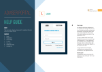
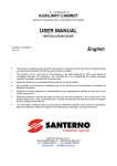
English
Light Series
User manual
LILBNAG0-01
1 Introduction to the user manual ...............................................................................................
1.1 General instructions...........................................................................................................
1.2 Conventions.......................................................................................................................
1.3 Documentation...................................................................................................................
2
2
2
2
2 Light series radio remote controls...........................................................................................
2.1 General description............................................................................................................
2.2 Safety functions .................................................................................................................
2.3 Conformity .........................................................................................................................
2.4 Risk analysis......................................................................................................................
2.5 Working conditions ............................................................................................................
2.6 General technical data.......................................................................................................
2.7 Identification plates and technical data plates ...................................................................
2.8 Storage ..............................................................................................................................
3
3
3
4
4
5
5
5
6
3 Transmitting unit........................................................................................................................
3.1 Signals ...............................................................................................................................
3.2 Technical data ...................................................................................................................
3.3 Climatic conditions.............................................................................................................
6
6
6
7
4 Receiving unit ............................................................................................................................ 7
4.1 Technical data ................................................................................................................... 8
4.2 Climatic conditions............................................................................................................. 8
5 Warnings for use........................................................................................................................ 8
6 How the radio remote control works........................................................................................ 9
6.1 Commands ........................................................................................................................ 9
6.2 Recharging the battery .................................................................................................... 10
7 Warnings for installation......................................................................................................... 10
8 Programming............................................................................................................................ 12
8.1 Transmitting module E16STXEU_................................................................................... 12
8.2 Receiving module E16SRXEU_ ...................................................................................... 13
9 Frequencies..............................................................................................................................
9.1 Manual selection mode....................................................................................................
9.2 Automatic scan mode ......................................................................................................
9.3 Manual selection of the working frequency......................................................................
13
13
14
14
10 Maintenance ............................................................................................................................. 14
10.1 Routine maintenance....................................................................................................... 15
10.2 Special maintenance (AUTEC SERVICE) ....................................................................... 16
11 Diagnostics............................................................................................................................... 16
11.1 Transmitting unit diagnostics ........................................................................................... 17
11.2 Receiving unit diagnostics ............................................................................................... 17
12 Disposal .................................................................................................................................... 18
LILBNAG0-01.fm
Page 1
English
INDEX
1
INTRODUCTION TO THE USER MANUAL
English
1.1 GENERAL INSTRUCTIONS
This manual is an integral part of the radio remote control and of its safety functions.
This manual shall complete the instructions provided by the producer of the remote controlled machine and/or by those who install the radio remote control on the machine.
All radio remote control installation, usage and maintenance operations can only be carried
out by qualified technicians who are suitably trained with respect to the relevant norms and
laws.
The radio remote control owner, installer, user, the person in charge of its maintenance and the responsible for the safety on the workplace where the radio remote control is used must therefore read
and understand each part of this manual.
As for instructions and warnings regarding the machine where the radio remote control is installed, follow the instructions given in the machine's manual.
No part of this manual may be reproduced, in any form or by any means, without written permission
of Autec (including recording and photocopying).
Always remember that:
1. the documentation must be kept for the whole life of the radio remote control: after reading, keep
it on hand for future reference
2. photos in this manual are useful examples that help understand the instructions and warnings of
each radio remote control configuration
3. if necessary, contact Autec if any of the instructions and/or warnings given in this manual are not
clear
4. if this manual is lost or damaged, ask Autec for a copy. Please specify the serial number of the
related radio remote control.
1.2 CONVENTIONS
In this manual, all important information is highlighted through the following symbols and conventions:
abcd…
abcd…
: WARNINGS
: IMPORTANT TEXTS
1.3 DOCUMENTATION
The documentation enclosed with each radio remote control is inside a plastic envelope and consists
of:
- manual of the radio remote control (one for each language)
- EC Declaration of Conformity
- guarantee booklet
- technical data sheet
- guarantee activation code (see label on the plastic envelope).
The battery charger package also includes the manual of the battery charger.
When purchasing a radio remote control, always make sure that such documents have been
supplied: if they are not, please ask for them to Autec specifying the radio remote control serial number.
Guarantee booklet
The guarantee can be activated in the specific area at www.autecsafety.com. Type the serial number
and the radio remote control activation code to register (see label on the plastic envelope containing
the documentation).
Page 2
LILBNAG0-01.fm
Technical data sheet
The technical data sheet shows the wiring diagram between the receiving unit and the machine. The
technical data sheet must be filled in, checked and kept updated by the installer, who is responsible
for correct wiring. Once all necessary checks have been carried out, the installer must undersign the
technical data sheet, which must be kept with the radio remote control documentation (always keep
a copy of this data sheet for administrative purposes).
2
LIGHT SERIES RADIO REMOTE CONTROLS
Autec industrial radio remote controls are used to control machines from a distance, without physical connection between
the user and the machine (i.e. wires or connecting cables).
Each industrial radio remote control consists of a portable
transmitting unit, from which the user can remotely control
the machine, and a receiving unit installed on board the machine itself.
The transmitting unit, through a radio transmission, sends
coded messages that contain commands that will be carried
out by the machine. Each message contains an address that
is: unique (Autec produces it only once), univocal (specific
for each radio remote control) and not reproducible. The receiving unit can only decode the messages coming from its
own transmitting unit with the same address.
If the radio transmission is disturbed, incorrect or interrupted,
the receiving unit autonomously stops the whole system thanks to the passive stop feature.
These features of the radio remote control avoid the possibility of an interference from another radio
equipment (e.g. a radio remote control) activating any system function.
2.2 SAFETY FUNCTIONS
Autec radio remote controls are equipped with some functions that provide high safety levels, in order
to safeguard the safety of people and things.
Active stop
“Active stop” is a command that is activated by the STOP pushbutton (see paragraph 6.1) and is sent
by the transmitting unit to the receiving unit in order to immediately stop the machine if the machine
needs to be stopped to avoid possible hazards of damage to people and/or properties.
This function boosts the machine safety, so that the machine stops in less time than the time needed
for stopping with the “passive stop” (see paragraph 2.6).
Passive stop
The “passive stop” is a function that will cut in should a fault occur during operation. Should the radio
link be disturbed, incorrect or interrupted, the receiving unit autonomously and automatically stops
the radio remote control features.
The cut in time (see paragraph 2.6) of such function can be set (see paragraph 8.2).
Protection against unintended movements from the standstill position (UMFS)
This safety function protects the system “machine+radio remote control” from unintended movements, namely machine movements not activated intentionally by the user, but resulting from possible electrical and mechanical failure of the radio remote control.
Such safety function constantly checks the neutral (rest) position of those actuators that drive the machine's movements. Each time one of those actuators is operated, the transmitting unit sends not only
the movement command but also the “SAFETY” movement command. This command activates the
SAFETY relay in the receiving unit; such relay must be wired as explained in the wiring instructions
LILBNAG0-01.fm
Page 3
English
2.1 GENERAL DESCRIPTION
provided on the technical data sheet (see paragraph 1.3) and the instructions for correct installation
and maintenance (see chapters 7 and 10).
2.3 CONFORMITY
Each radio remote control is in conformity with the R&TTE Directive 99/05/CE and its essential
safety requirements.
Each radio remote control is also in conformity with the standards given in the EC Declaration
of Conformity that is enclosed with this manual.
The radio remote control shall be used in compliance with the laws and regulations in
force in the Country where it is used. In particular, when installing and using the radio
remote control, national laws that regulate the following aspects must be respected:
- the use and/or possession of a radio remote control
- the use of working frequencies that are not yet harmonised in the European countries,
that is, frequencies that are not used uniformly within the European Union.
Light series radio remote controls can work in the frequency bands 433.05 - 434.79 MHz, 434.04 434.79 MHz and 869.70 - 870.00 MHz in the countries shown in the following table.
Austria
Belgium
Bulgaria
Cyprus
Czech Republic
Denmark
Estonia
Finland
France
Germany
Greece
Hungary
Iceland
Ireland
Italy
Latvia
Liechtenstein
Lithuania
Luxembourg
Malta
Netherlands
Norway
Poland
Portugal
Romania
Slovakia
Slovenia
Spain
Sweden
Switzerland
United Kingdom
English
Limitations & Authorisations
433.05 - 434.79 (MHz)
434.04 - 434.79 (MHz)
869.70 - 870.00 (MHz)
•
•
• • • • • • • • • • • • • • • • • • • • • • • • • • • • •
• • • • • • • • • • • • • • • • • • • • • • • • • • • • • • •
2.4 RISK ANALYSIS
Autec industrial radio remote controls are intended to be used on hoisting and material handling machines (i.e. cranes, overhead cranes).
As provided by the Machinery Directive and its subsequent amendments and additions, when installing the radio remote control the machine producer or those who install the radio remote control on
the machine must carry out a specific risk analysis. Such analysis aims at deciding if the machine, for
its structural and/or functional features, can be operated by means of a radio remote control system.
In particular, the developer and/or the machine producer that plans to equip it with a radio remote
control, or the installer of the radio remote control on the machine, are responsible for evaluating if
installing a radio remote control may generate risks for the safety of people and/or properties, and
shall evaluate in advance whether the machine may be remote controlled.
All instructions and warnings provided in this manual must be taken into account when carrying out the risk analysis and when setting out protection measures and safety systems for
the controlled machine.
The machine producer and/or the person who decides upon radio remote control use and installation
is responsible for this analysis.
Autec shall not be held liable if this risk analysis is not carried out correctly.
Page 4
LILBNAG0-01.fm
Forbidden uses
Forbidden applications are:
- machines installed in areas where equipment with explosion-proof characteristics is
required and/or
- machines for moving, raising and transporting people.
Autec shall not be held liable if the radio remote control is installed on forbidden applications.
To guarantee correct radio remote control operation, all current regulations regarding safety at work
and accident prevention should be respected. All applicable standards and regulations valid in the
user country regarding the use of both the machine and the radio remote control must always be respected.
In particular, users of the remote controlled machine must be preventively and properly trained about
the use of the machine, the radio remote control and the implemented safety and emergency features.
Autec shall not be held liable if the radio remote control is used in working conditions that do
not meet the legislative provisions in force in the country where the device is used.
2.6 GENERAL TECHNICAL DATA
Frequency band with radio module E16SRXEU1 a....................................... 434.04 - 434.79 MHz
.................................................................................................................. or 433.05 - 434.79 MHz
Frequency band with radio module E16SRXEU2 ......................................... 869.70 - 870.00 MHz
Available radio channels ........................................................................ 16 (434.04 - 434.79 MHz)
............................................................................................................... 32 (433.05 - 434.79 MHz)
............................................................................................................... 12 (869.70 - 870.00 MHz)
Channel spacing ................................................................................................................. 25 kHz
Hamming distance ..................................................................................................................... ≥ 8
Probability of undetected error ...................................................................................... <10 exp-11
Typical working range ............................................................................................................. 50 m
Command response time ................................................................................................. ~ 100 ms
Active stop timeb .............................................................................................................. ~ 100 ms
Passive stop timec ............................................................................................................. 0.35/1 s
STOP protection (according to the EN 954-1) ...................................................................... Cat. 3
a. See paragraph 2.3 to select the permitted working band and chapter 8 if setting is necessary.
b. Valid when the radio link between transmitting and receiving unit is not disturbed.
c. Refer to paragraph 8.2, DIP No. 1 settings.
Due to the characteristics of radio propagation (i.e.: EM interferences, near out-of-range
condition), a delay up to one second may occasionally occur from the moment a command in the transmitting unit is released to the moment its corresponding output in the
receiving unit is deactivated. Those who decide upon the installation of the radio remote
control must make sure that this delay never leads to a dangerous situation in the specific uses.
2.7 IDENTIFICATION PLATES AND TECHNICAL DATA PLATES
Autec radio remote controls' identification and approval data are given on plates that are on both the
transmitting unit and the receiving unit.
These plates must not be:
- removed from their position (removal will invalidate the guarantee)
- altered or damaged (contact Autec for replacement).
LILBNAG0-01.fm
Page 5
English
2.5 WORKING CONDITIONS
2.8 STORAGE
Radio remote controls must be stored inside their original packing until they are installed on the machine.
Environmental storage conditions are given in the relevant table (see paragraphs 3.3 and 4.2).
3
TRANSMITTING UNIT
The number of pushbuttons in the LK transmitting unit varies depending on its configuration.
English
D
C
E
F
G
B
A
starting keyswitch
E
technical data plate
B
Signalling LED
F
START pushbutton
C
pushbuttons
G
identification plate
(in the battery housing)
D
STOP pushbutton
H
battery
H
A
3.1 SIGNALS
LED (B)
switched off
a single blinking
MEANING
transmitting unit switched off or not started
actuator inserted during start up
slow blinking
transmitting unit is started
fast blinking
low battery: the transmitting unit switches off 3.5 minutes after the LED
starts blinking fast
3.2 TECHNICAL DATA
Power supply (battery pack MBM06MH)a................................................................. NiMH 2.4 Vdc
Antenna .............................................................................................................................. internal
Transmitting power (frequency band 433.05 - 434.79 MHz) ................................... ≤ 10 mW ERP
Transmitting power (frequency band 869.70 - 870.00 MHz) ..................................... ≤ 5 mW ERP
Housing....................................................................................................................PA 66 (50% fg)
Protection degree .....................................................................................................................IP65
Dimensions ......................................................................................................... 80 x 185 x 43 mm
Weight .................................................................................................................................... 420 g
Battery capacity with fully charged battery (at 20°C) ............................................................ > 12 h
"Low battery" warningb ....................................................................................................... 3.5 min
a. Refer to battery technical data in the battery charger manual.
b. Refer to paragraph 8.1, DIP No. 2 setting.
Page 6
LILBNAG0-01.fm
4
TEMPERATURE
RELATIVE
HUMIDITY
AIR PRESSURE
WORKING
Class 4K4H
-20°C to +55°C
Class 4K4H
4% to 100%
Class 4K4H
86 kPa to 106 kPa
STORAGE
Class 1K5
-40°C to +70°C
Class 1K3
5% to 95%
Class 1K4
86 kPa to 106 kPa
TRANSPORTATION
Class 2K3
-25°C to +70°C
Class 2K3
95%
Class 2K3
70 kPa to 106 kPa
RECEIVING UNIT
L
N
O
DRILLING
TEMPLATE
I cable gland
M
J POWER light
N=106 mm
K ENABLE light
L technical data plate
O=82 mm
Q
P
P=213.5 mm
Q=222 mm
M identification plate
K
J
I
The receiving unit is equipped with some status indicating lights:
POWER light (J)
receiving unit is powered
ENABLE light (K)
radio link between the units is present
The mother board in this receiving unit is the E16B11AC.
F1 POWER SUPPLY protection fuse
F2 SAFETY circuit protection fuse
F3
STOP circuit protection fuses
F4
LILBNAG0-01.fm
Page 7
English
3.3 CLIMATIC CONDITIONS
English
4.1 TECHNICAL DATA
Receiving unit power supply ............................................................. Nom. 24 - 48 Vac/dc (~ 10W)
........................................................................................................................ Max. 20 - 60 Vac/dc
Antenna .............................................................................................................................. internal
STOP contact rated current ....................................................................................... 4 A (250 Vac)
SAFETY contact rated current................................................................................... 4 A (250 Vac)
Command contact rated current ................................................................................ 6 A (250 Vac)
Fuse F1 (POWER SUPPLY) .................................................................. 0.8 A T 250 V (5x20 mm)
Fuse F2 (SAFETY circuit)............................................................................4 A T 250V (5x20 mm)
Fuse F3 and F4 (STOP circuit)...................................................................4 A T 250 V (5x20 mm)
Housing......................................................................................................................PA 6 (20% fg)
Protection degree .....................................................................................................................IP65
Dimensions ....................................................................................................... 123 x 202 x 83 mm
Weight.................................................................................................................................... 1.2 kg
4.2 CLIMATIC CONDITIONS
TEMPERATURE
RELATIVE
HUMIDITY
AIR PRESSURE
WORKING
Class 4K4H
-20°C to +70°C
Class 4K4H
4% to 100%
Class 4K4H
86 kPa to 106 kPa
STORAGE
Class 1K5
-40°C to +70°C
Class 1K3
5% to 95%
Class 1K4
86 kPa to 106 kPa
TRANSPORTATION
Class 2K3
-25°C to +70°C
Class 2K3
95%
Class 2K3
70 kPa to 106 kPa
5
WARNINGS FOR USE
The user must always respect the following warnings:
Stand in a position that allows the direct supervision of the remote controlled machine
and its load, and stay in a place ensuring safety conditions in respect of other operations and/or activities and/or processes that are carried out in the working environment.
Visually follow all movements of the machine and its load and remain inside the typical
working range of the radio remote control.
When using the radio remote control pay particular attention to warnings and visual and
acoustic signals and take all measurements and steps to avoid that movements of the remote controlled machine may lead to hazardous situations for people and/or properties.
Before using the radio remote control always make sure that the STOP pushbutton can
be pressed and released: if it does not work, do not use the radio remote control.
Switch off the transmitting unit when work is stopped or temporarily interrupted. Do not
leave the load hanging (even when changing the battery).
Never leave the transmitting unit unguarded when the starting keyswitch is inserted.
Switch on or use the transmitting unit only when starting work: improper use could be
hazardous.
Page 8
LILBNAG0-01.fm
Never switch on or use the transmitting unit in closed spaces, with the machine not in
sight, or outside the radio remote control typical working range.
Immediately press the STOP pushbutton in case of hazard.
Pay attention to the entire work area. Press the STOP pushbutton in case of hazard.
6
HOW THE RADIO REMOTE CONTROL WORKS
6.1 COMMANDS
Power on
Power on the receiving unit (POWER light on) and insert the starting keyswitch to switch on the transmitting unit.
Start up
With the radio remote control on, keep the START pushbutton pressed, until the signalling LED and
the ENABLE light start blinking.
Command activation
With the radio remote control on, act
on the pushbutton corresponding to
the command to be carried out.
The activation of each relay on the receiving unit mother board is signalled
by an LED (R) near the relay.
STOP
R
The STOP pushbutton should
be pressed when it is necessary to stop the machine immediately when a dangerous
condition should occur.
To stop the machine immediately in case of hazard, press the STOP pushbutton.
To start working again, after checking that the working and usage conditions are safe, turn the
STOP pushbutton in the direction indicated to deactivate it and repeat the starting procedure.
The STOP circuit complies with category 3 according to the EN 954 - 1.
Switching off
The transmitting unit shall be switched off each time work is stopped or even only temporarily
interrupted, by extracting the starting keyswitch (always put the key in a safe place).
The transmitting unit can also switch off automatically when the battery is flat and when the transmitting unit is not being used.
If the battery is not sufficiently charged, this condition is reported on the transmitting unit (see
paragraph 3.1). After the “low battery” warning time is passed (see paragraph 3.2), the transmitting
unit automatically switches off. The battery shall be replaced with a charged one.
The transmitting unit will also automatically switch off when it stays switched on and started for approx. 3.5 minutes without any movement command activated. This feature can be disabled (see
paragraph 8.1).
LILBNAG0-01.fm
Page 9
English
In case of malfunction, disable the system “machine+radio remote control” until the
problem has been completely solved.
6.2 RECHARGING THE BATTERY
English
The transmitting unit is powered by a rechargeable battery.
To recharge a low battery, proceed as follows:
1. insert the battery into its proper battery charger, which should be positioned in an area with a temperature between 5°C and +45°C: the battery now starts charging, a state signalled by the lighting
up of the “CHARGE” pilot light.
2. after a maximum of four hours the "CHARGE" light switches off: the battery is fully charged and
can be removed. If it is not removed from the battery charger, the charger switches to trickle charging.
For any warnings and instructions regarding the batteries and the battery charger, please refer
to the battery charger manual.
7
WARNINGS FOR INSTALLATION
The radio remote control can only be installed and tested by competent staff, that masters the technical knowledge required to carry out such procedure and are qualified according to the regulation of the country where the radio remote control is mounted.
The installer must always respect the following warnings:
Place the receiving unit vertically, with the cable gland facing down.
Install the receiving units so that shields, structures or materials do not obstruct the radio link; in particular:
- the receiving unit must be directed towards the work area
- the receiving unit must not be shielded by metal objects.
- the receiving unit must be installed at least 50 cm far from metal objects or structures.
If this warning is disregarded, the typical working range of the radio remote control may be reduced.
Place the receiving unit so that it can be easily reached in case of need.
Fix the receiving unit in four points, using the specific holes in the housing.
When installing on machines that vibrate, it is recommended to fix the receiving unit to the machine with the appropriate vibration dampers.
Do not modify or tamper with the radio remote control, the machine or its electrical panel. Do not perforate the receiving unit in any case.
Page 10
LILBNAG0-01.fm
Make sure that the receiving unit is powered by:
- a 24 Vdc battery or
- a power supply unit with a safety isolating transformer supplying at least 10 VA, or
- a safety isolating transformer supplying at least 10VA.
The receiving unit power supply must be protected from short circuit.
Check that the receiving unit power supply is within the voltage limits given in the technical data, and that voltages and currents being used when working with the radio remote control do not exceed the maximum permitted values (see paragraph 4.1).
Respect and enforce the provisions of the EN60204-32 (for hoisting machines) and/or
EN60204-1 regulations (for machines).
The power supply of the receiving unit must have a switch that allows power supply disconnection during installation, wiring and/or maintenance operations. Connect the receiving unit immediately downstream of the machine main switch or of the electrical
panel main switch.
Remember to carefully wire the contact of the SAFETY relay in series with the common
of all movement commands inside the receiving unit.
Receiving unit
common
wire input
fuse
movement
command
common wire
Group the wiring away from the radio module, in order to avoid interferences and hazards related to electrical safety.
After having installed and wired the receiving unit, always check that the manoeuvres
carried out are exactly the same as the commands given (in particular check the STOP
command).
Do not remove the jumper between terminals 2 and 3 in the receiving unit: such wiring
is needed to connect in series the two contacts of the STOP circuit and is essential to
obtain category 3 to EN 954-1.
It is however possible that the machine to be remote controlled provides for a STOP circuit with 4 wires and the separate use of the two contacts. In this case the jumper can
only be removed under the responsibility of the installer, who shall carry out wiring in
a way that assures the required safety category (up to cat. 3 to EN 954-1).
After installation and wiring, test the system “machine+radio remote control”, and
check that the operations carried out correspond exactly to the commands sent (in particular check the STOP command).
In case of malfunction, disable the system “machine+radio remote control” until the
problem has been completely solved.
At the end of installation, correctly close the receiving unit so that the protection degree
from dust and water is not jeopardised: check that the gasket is intact, correctly put the
housing parts one over the other so that they overlap, and screw up the screws.
The installer must check and fill in the "Technical Data Sheet" in all its parts, adding the date the system has been put into service, his stamp and signature.
LILBNAG0-01.fm
Page 11
English
Make sure that during installation the safety mechanisms on the radio remote control
and/or in the machine have not been made ineffective by possible procedures carried out.
8
PROGRAMMING
DIP switches can only be programmed by authorised personnel; programming is only
possible when the receiving unit is not powered and the battery has been removed from
the transmitting unit.
English
For the correct functioning, the group of 8 DIP switches (excluding DIP 1) for the radio
module E16STXEU_ in the transmitting unit and E16SRXEU_ in the receiving unit must
be set in the same way.
At the end of programming, correctly close the receiving and the transmitting unit so
that the protection degree from dust and water is not jeopardised: check that the gasket
is intact, correctly put the housing parts one over the other so that they overlap, and
screw up the screws.
8.1 TRANSMITTING MODULE E16STXEU_
The group of eight dip switches located on the radio module are used to program some functions and
set the working frequency.
Group of 8 DIP
switches
Group of 4
DIP switches
DIP
MODULE
1
E16STXEU_
2
E16STXEU_
STATE
ON
The transmitting unit never switches off automatically
OFF
If the transmitting unit stays switched on without any commands activated, it switches off after approx. 3.5 minutes.
ON
Deactivation of low battery warning from horn on machine
OFF
Activation of low battery warning from horn on machine
ON
If DIP 8 is OFF, automatic scan of the frequencies in the band
433.05 - 434.04 MHz
OFF
If DIP 8 is OFF, automatic scan of the frequencies in the band
434.04 - 434.79 MHz
ON
DO NOT USE
OFF
If DIP 8 is OFF, automatic scan of the frequencies in the band
869.70 - 870.00 MHz
E16STXEU1
3
E16STXEU2
FUNCTION
3-7 E16STXEU_ ON/OFF If DIP 8 is ON, see paragraph 9.3
8
ON
Manual selection mode of the frequencies using DIP 3 - DIP 7 (see
paragraph 9.3)
OFF
Automatic scan mode of the frequencies in the band selected by DIP
3 (DIP 4 - DIP 7 indifferent)
E16STXEU_
All DIP switches in the group of four shall always be set at OFF.
Page 12
LILBNAG0-01.fm
8.2 RECEIVING MODULE E16SRXEU_
The group of eight DIP switches located on the radio module are used to program some functions
and set the working frequency.
Group of 8
DIP switches
Group of 4
DIP switches
MODULE
1
E16SRXEU_
2
E16SRXEU_
STATE
ON
E16SRXEU2
Stop after 0.35 seconds with invalid radio signal
OFF
Stop after 1 second with invalid radio signal
ON
Deactivation of low battery warning from horn on machine
OFF
Activation of low battery warning from horn on machine
ON
If DIP 8 is OFF, automatic scan of the frequencies in the band
433.05 - 434.04 MHz
OFF
If DIP 8 is OFF, automatic scan of the frequencies in the band
434.04 - 434.79 MHz
ON
DO NOT USE
OFF
If DIP 8 is OFF, automatic scan of the frequencies in the band
869.70 - 870.00 MHz
E16SRXEU1
3
FUNCTION
3-7 E16SRXEU_ ON/OFF If DIP 8 is ON, see paragraph 9.3
8
ON
Manual selection mode of the frequencies using DIP 3 - DIP 7 (see
paragraph 9.3)
OFF
Automatic scan mode of the frequencies in the band selected by
DIP 3 (DIP 4 - DIP 7 indifferent)
E16SRXEU_
All DIP switches in the group of four shall always be set at OFF.
9
FREQUENCIES
Radio frequency transmission of Autec radio remote controls operates inside frequency
bands permitted by European regulations that are valid when the radio remote control is
placed on the market.
The use of the 869.70 - 870.00 MHz frequency band has been harmonised in Europe,
whereas the use of 433.05 - 434.79 MHz frequencies band has not been harmonised in
Europe yet. Check which frequency band can be used in each of the European countries
(see paragraph 2.3).
Each radio remote control is programmed by the producer in the automatic scan mode (producer's
standard programming) or manual selection mode.
9.1 MANUAL SELECTION MODE
When operating in the manual selection mode it is possible to work at a specific frequency that must
be set manually by programming the dip switches in the radio modules (see paragraph 9.3).
To set or modify this operation mode contact authorised Autec personnel.
LILBNAG0-01.fm
Page 13
English
DIP
9.2 AUTOMATIC SCAN MODE
When operating in the automatic scan mode it is possible to operate at a specific frequency, which
can be changed in case of interference or conflict with other radio systems, using the “Changing the
working frequency” procedure.
This mode allows to change the working frequency without internal interventions on the transmitting
unit or the receiving unit.
English
Changing the working frequency (see chapter 6)
1. With the transmitting unit started (LED blinks):
- press the START pushbutton and keep it pressed
- press the STOP pushbutton
- release the START pushbutton.
2. Unlock the STOP pushbutton by turning it as shown in the photo and repeat the starting procedure.
N.B.: During the working frequency changing process, the receiving unit loses radio link with the
transmitting unit. After starting, some seconds may be necessary to reset connection, therefore keep
the START pushbutton pressed for about 8-10 seconds.
9.3 MANUAL SELECTION OF THE WORKING FREQUENCY
433.05-434.04 MHZ
MHZ
433.125
433.200
433.250
433.325
433.400
433.425
433.475
433.500
433.575
433.625
433.700
433.775
433.825
433.900
433.950
434.025
3
ON
ON
ON
ON
ON
ON
ON
ON
ON
ON
ON
ON
ON
ON
ON
ON
DIP SWITCHES
4
5
6
7
OFF OFF OFF OFF
OFF OFF ON OFF
OFF OFF OFF ON
ON ON OFF ON
ON OFF OFF OFF
ON OFF ON OFF
ON OFF OFF ON
ON ON ON ON
OFF OFF ON ON
OFF ON OFF OFF
OFF ON ON OFF
ON OFF ON ON
OFF ON OFF ON
ON ON OFF OFF
OFF ON ON ON
ON ON ON OFF
434.04-434.79 MHZ
8
ON
ON
ON
ON
ON
ON
ON
ON
ON
ON
ON
ON
ON
ON
ON
ON
MHZ
434.100
434.125
434.150
434.225
434.300
434.325
434.350
434.375
434.400
434.475
434.500
434.525
434.600
434.675
434.700
434.725
3
OFF
OFF
OFF
OFF
OFF
OFF
OFF
OFF
OFF
OFF
OFF
OFF
OFF
OFF
OFF
OFF
DIP SWITCHES
4
5
6
7
OFF OFF OFF OFF
OFF OFF ON OFF
ON ON ON OFF
OFF ON OFF ON
ON OFF ON ON
ON OFF OFF OFF
ON OFF ON OFF
OFF OFF OFF ON
ON ON OFF ON
OFF ON ON ON
OFF ON OFF OFF
OFF ON ON OFF
ON OFF OFF ON
OFF OFF ON ON
ON ON OFF OFF
ON ON ON ON
869.70 - 870.00 MHZ
8
ON
ON
ON
ON
ON
ON
ON
ON
ON
ON
ON
ON
ON
ON
ON
ON
MHZ
869.7125
869.7375
869.7375
869.7625
869.7875
869.8125
869.8125
869.8375
869.8625
869.8875
869.8875
869.9125
869.9375
869.9625
869.9625
869.9875
3
OFF
OFF
OFF
OFF
OFF
OFF
OFF
OFF
OFF
OFF
OFF
OFF
OFF
OFF
OFF
OFF
DIP SWITCHES
4
5
6
7
OFF OFF OFF OFF
OFF OFF ON OFF
OFF OFF ON ON
OFF OFF OFF ON
ON OFF OFF OFF
ON OFF ON ON
ON OFF ON OFF
ON OFF OFF ON
OFF ON OFF OFF
OFF ON ON ON
OFF ON ON OFF
OFF ON OFF ON
ON ON OFF OFF
ON ON ON ON
ON ON ON OFF
ON ON OFF ON
8
ON
ON
ON
ON
ON
ON
ON
ON
ON
ON
ON
ON
ON
ON
ON
ON
10 MAINTENANCE
The following instructions provide information to safely carry out routine and special maintenance operations for the radio remote control.
They shall be completed by:
- instructions provided by the machine producer;
- instructions provided by the installer;
- regulations regarding safety at work and accident prevention in force in the country where
the radio remote control is used.
All fine-tuning, checking and maintenance actions carried out on the radio remote control shall be verified and recorded by the person in charge of carrying out maintenance on the machine.
In case of failure, emergencies or damaged parts, disable the system “radio remote control+machine” until the problem has been completely solved.
Page 14
LILBNAG0-01.fm
At the end of maintenance, correctly close the receiving and the transmitting unit so
that the protection degree from dust and water is not jeopardised: check that the gasket
is intact, correctly put the housing parts one over the other so that they overlap, and
screw up the screws.
When maintenance is carried out on the machine (i.e. when soldering), remove power
supply by disconnecting all electric connections (both during installation and during
normal operation).
Routine maintenance consists of operations needed to preserve the radio remote control normal usage conditions, thus implementing fine-tuning, checks, planned replacement actions that necessarily
arise from the normal use of the product.
All given instructions must be followed correctly at each commissioning, that is:
- whenever the radio remote control and/or the machine is installed or assembled,
- whenever the machine location/position changes
- after special maintenance.
Routine maintenance carried out as described in this manual is fundamental for using
the radio remote control safely.
Before carrying out routine maintenance, it is recommended to replace the battery with
a charged one and to ensure the efficiency of the starting keyswitch.
Special applications may need more specific routine maintenance actions to be carried out at different periods (i.e. if the working environment is particularly dirt, or in case of heavy application or if it is
used very frequently, some maintenance actions may be required more frequently, depending on the
decision of the person in charge for safety).
Daily maintenance
1. Make sure that materials that could endanger the transmitting unit usage and safety (such as concrete, sand, lime, dust) do not deposit on it.
2. Never use solvents or flammable/corrosive materials to clean the transmitting unit, and do not use
high-pressure water cleaners or steam cleaners.
3. Store the transmitting unit in clean and dry areas.
4. Make sure that the gaskets, bellows and caps of the actuators of the transmitting unit are intact,
soft and elastic.
5. Make sure that the battery housing and the battery contacts are always clean.
6. Check structural integrity of the transmitting unit.
7. Make sure that the transmitting unit panel symbols can be easily recognised and replace the panel
if necessary.
8. Check that the identification plate and the technical data plate on the transmitting unit are readable
and not damaged.
9. Make sure that the STOP pushbutton works properly before using the radio remote control.
Three-month maintenance
1. Remove dust or accumulations of other material from the receiving unit: never use solvents or flammable/corrosive materials to clean, and do not use high-pressure water cleaners or steam cleaners
2. Check structural integrity of the receiving unit.
3. Check that the wiring of the receiving unit is intact and connected.
4. Make sure that the receiving unit panel symbols can be easily recognised and replace the panel if
necessary.
5. Check that the identification plate and the technical data plate on the receiving unit are readable
and not damaged.
LILBNAG0-01.fm
Page 15
English
10.1 ROUTINE MAINTENANCE
Half yearly maintenance
1. Make sure that all the relay contacts of the receiving unit operate correctly, and check that the contact closes when the corresponding manoeuvre is enabled and opens when the manoeuvre is disabled
2. Check the correct correspondence between the commands that are sent and the manoeuvres that
are carried out by the machine.
3. Check that the contact for the SAFETY relay is open when no command has been sent. This is
safety critical maintenance: it is necessary to keep a record (date, signature, comments) showing
that this check has been regularly carried out. Keep the record together with other installation documents.
English
10.2 SPECIAL MAINTENANCE (AUTEC SERVICE)
Special maintenance consists of repairs needed due to radio remote control failure, damage
or malfunction, carried out with the aim of restoring the original usage and working conditions.
Always ensure that the receiving unit has been disconnected from the power source before carrying out any special maintenance work.
Any fault should be repaired by authorised personnel (contact Autec Service), using
original Autec spare parts only.
After each special maintenance action, always make sure that commands sent by the
transmitting unit only activate the corresponding expected operations.
It is recommended to read and understand all parts of this manual, and make sure that all the
instructions it contains have been followed correctly before contacting the Autec Service.
The following radio remote control data must be communicated in order to make interventions faster
and more reliable:
- serial number
- purchase date
- description of the problem found
- address and telephone number of the place where the device is being used (with the name of the
person to contact)
- local supplier.
11 DIAGNOSTICS
Diagnostics aims at checking that the radio remote control works properly.
If the system “machine+radio remote control” does not start, check if the problem is caused by the
radio remote control or the machine. Therefore, before carrying out any verification connect the cable
control unit: if the machine does not start, the problem lies with the machine.
If, on the other hand, the machine only starts using the cable control unit, the problem lies with the
radio remote control. In this case, proceed as explained in the following paragraphs.
Page 16
LILBNAG0-01.fm
11.1 TRANSMITTING UNIT DIAGNOSTICS
YES
STOP pushbutton
or one of the
actuators is
activated:
disconnect it/them.
Does the LED blink
once during the radio YES
remote control startup stage?
NO
Does the
LED (B) blink
fast?
NO
YES
The battery is discharged: replace it
with a fully charged
one. Does it continue to blink fast?
NO
Does the LED (B)
blink slowly?
YES
YES
NO
NO
YES
Clean contacts in
the battery
housing. Does it
still blink fast?
If the problem
persists, carry out
diagnostics checks
on the receiving
unit
CALL THE
AUTEC SERVICE
NO
11.2 RECEIVING UNIT DIAGNOSTICS
Is the POWER
light on?
YES
YES
Is the ENABLE
light on?
NO
Correctly insert
the connecting
plug and start
the radio remote
control
YES
YES
NO
Carry out the
frequency change
NO
procedure (see
chapter 9). Does
the machine start?
LILBNAG0-01.fm
Is the connecting
plug between the
radio remote control
and the machine
connected
correctly?
Remove power from
the receiving unit.
Check fuses. Are
they intact?
NO
Check the
power supply
connections.
NO
Replace blown fuses. Connect to power source and switch
on radio remote
control. Does the
machine start?
YES
CALL THE
AUTEC SERVICE
Page 17
English
Does the LED blink
once during the
radio remote control
start-up stage?
12 DISPOSAL
English
When disposing of a radio remote control, give it to the waste separate collecting services in the user's country.
Please pay particular attention when recycling the batteries, applying local rules. Do not throw them
away with domestic trash.
Page 18
LILBNAG0-01.fm
www.autecsafety.com
Autec s.r.l.
Via Pomaroli, 65 - 36030 Caldogno (VI) Italy
tel +39.0444.901000 - fax +39.0444.901011