1
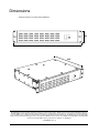
P3 PowerPort 1500™
User Manual
Dimensions
All measurements are expressed in millimeters
88
482
335
© 2012 Martin Professional A/S. Information subject to change without notice. Martin Professional A/S and all affiliated companies
disclaim liability for any injury, damage, direct or indirect loss, consequential or economic loss or any other loss occasioned by the
use of, inability to use or reliance on the information contained in this document. The Martin logo, the Martin name and all other trademarks in this document pertaining to services or products by Martin Professional A/S or its affiliates and subsidiaries are trademarks
owned or licensed by Martin Professional A/S or its affiliates or subsidiaries.
P/N 35000261, Rev. A
Contents
Safety Information . . . . . . . . . . . . . . . . . . . . . . . . . . . . . . . . . . . . . . . . . . . . . . . . . . . . . . . . . . . . . . . . . . 4
Introduction . . . . . . . . . . . . . . . . . . . . . . . . . . . . . . . . . . . . . . . . . . . . . . . . . . . . . . . . . . . . . . . . . . . . . . . . 6
Unpacking . . . . . . . . . . . . . . . . . . . . . . . . . . . . . . . . . . . . . . . . . . . . . . . . . . . . . . . . . . . . . . . . . . . . . . . . 6
Overview . . . . . . . . . . . . . . . . . . . . . . . . . . . . . . . . . . . . . . . . . . . . . . . . . . . . . . . . . . . . . . . . . . . . . . . . . . 7
Front panel. . . . . . . . . . . . . . . . . . . . . . . . . . . . . . . . . . . . . . . . . . . . . . . . . . . . . . . . . . . . . . . . . . . . . . . . 7
Rear panel . . . . . . . . . . . . . . . . . . . . . . . . . . . . . . . . . . . . . . . . . . . . . . . . . . . . . . . . . . . . . . . . . . . . . . . . 7
Physical installation . . . . . . . . . . . . . . . . . . . . . . . . . . . . . . . . . . . . . . . . . . . . . . . . . . . . . . . . . . . . . . . . 8
AC power . . . . . . . . . . . . . . . . . . . . . . . . . . . . . . . . . . . . . . . . . . . . . . . . . . . . . . . . . . . . . . . . . . . . . . . . . . 9
AC mains power input . . . . . . . . . . . . . . . . . . . . . . . . . . . . . . . . . . . . . . . . . . . . . . . . . . . . . . . . . . . . . . . 9
DC power output . . . . . . . . . . . . . . . . . . . . . . . . . . . . . . . . . . . . . . . . . . . . . . . . . . . . . . . . . . . . . . . . . . 10
P3 video data . . . . . . . . . . . . . . . . . . . . . . . . . . . . . . . . . . . . . . . . . . . . . . . . . . . . . . . . . . . . . . . . . . . . . 11
P3 video data input . . . . . . . . . . . . . . . . . . . . . . . . . . . . . . . . . . . . . . . . . . . . . . . . . . . . . . . . . . . . . . . . 11
P3 video data output . . . . . . . . . . . . . . . . . . . . . . . . . . . . . . . . . . . . . . . . . . . . . . . . . . . . . . . . . . . . . . . 11
Using the product . . . . . . . . . . . . . . . . . . . . . . . . . . . . . . . . . . . . . . . . . . . . . . . . . . . . . . . . . . . . . . . . . 12
Applying power . . . . . . . . . . . . . . . . . . . . . . . . . . . . . . . . . . . . . . . . . . . . . . . . . . . . . . . . . . . . . . . . . . . 12
Status LEDs and control button . . . . . . . . . . . . . . . . . . . . . . . . . . . . . . . . . . . . . . . . . . . . . . . . . . . . . . . 12
Service and maintenance . . . . . . . . . . . . . . . . . . . . . . . . . . . . . . . . . . . . . . . . . . . . . . . . . . . . . . . . . . 14
Fuse replacement . . . . . . . . . . . . . . . . . . . . . . . . . . . . . . . . . . . . . . . . . . . . . . . . . . . . . . . . . . . . . . . . . 14
Cleaning. . . . . . . . . . . . . . . . . . . . . . . . . . . . . . . . . . . . . . . . . . . . . . . . . . . . . . . . . . . . . . . . . . . . . . . . . 14
Installing new software . . . . . . . . . . . . . . . . . . . . . . . . . . . . . . . . . . . . . . . . . . . . . . . . . . . . . . . . . . . . . 15
Troubleshooting . . . . . . . . . . . . . . . . . . . . . . . . . . . . . . . . . . . . . . . . . . . . . . . . . . . . . . . . . . . . . . . . . . 16
Specifications . . . . . . . . . . . . . . . . . . . . . . . . . . . . . . . . . . . . . . . . . . . . . . . . . . . . . . . . . . . . . . . . . . . . . 17
Safety Information
WARNING!
Read the safety precautions in this section before
installing, powering, operating or servicing this
product.
The following symbols are used to identify important safety information on the product and in this document:
Warning!
Warning!
Safety hazard.
Hazardous
Risk of severe voltage. Risk
injury or
of severe or
death.
lethal electric
shock.
Warning!
Fire hazard.
Warning!
Refer to
manual before
installing,
powering or
servicing.
Warning! Read this user manual before installing and operating the P3 PowerPort 1500.
Warning! The P3 PowerPort 1500 is designed to integrate with other devices in a video display
installation. Follow the safety precautions given not only in this user manual but also in the manuals
of all the devices you connect to it. Observe all warnings given in the manuals and printed on
devices. Install and operate devices only as described in the manuals and only in accordance with
local laws and regulations. Keep this manual for future reference. Manuals are supplied with devices
and also available for download from www.martin.com.
Warning! The Martin™ P3 PowerPort 1500 is not for household use. It presents risks of severe injury
or death due to fire and burn hazards, electric shock and falls. It must be installed by qualified
technicians only.
Warning! There are no user-serviceable parts inside the P3 PowerPort 1500. Refer any operation not
described in this manual to Martin™ or its authorized service agents.
If you have any questions about how to operate the P3 PowerPort 1500 safely, please contact your Martin™
supplier or call the Martin™ 24-hour service hotline on +45 8740 0000, or in the USA on 1-888-tech-180.
PROTECTION FROM ELECTRIC SHOCK
• The P3 PowerPort 1500 can supply a safe maximum current of 7.5 A on each of its four power + data
outputs. Do not connect devices that draw a combined total current of more than 7.5 A to a power + data
output.
• Check and respect the directions given in the user manuals of all the devices that you intend to connect to
the P3 PowerPort 1500, particularly the instructions, warnings and limits that apply to:
- system layout,
- connections to other devices,
- specified cables,
- maximum cable lengths, and
- maximum number of devices that can be connected.
• Provide a means of locking out AC mains power that allows power to the installation to be shut down and
made impossible to reapply, even accidentally, during work on the installation.
• Shut down power to the installation during service and when it is not in use.
4
P3 PowerPort 1500 Safety and Installation Guide
• Ensure that the P3 PowerPort 1500 is electrically connected to ground (earth).
• Connect the P3 PowerPort 1500 to AC mains power at 100-240 V (nominal), 50/60 Hz only.
• Use only a source of AC mains power that complies with local building and electrical codes and has both
overload and ground-fault (earth-fault) protection.
• Use only a power input cable that has 12 AWG or 4 mm² minimum conductor size and an outer cable
diameter of 10 - 15 mm (0.4 - 0.6 in.). Power cable must be hard usage type (SJT or equivalent) and
heat-resistant to 90° C (194° F) minimum. In the EU the cable must be HAR type.
• Use only the cables specified by Martin™ for the devices concerned to interconnect them. If the specified
cables are not long enough for an intended cable run, consult Martin™ for assistance in finding or
creating a safe alternative cable
• Before applying power to the installation, check that all power distribution equipment and cables are in
perfect condition and rated for the current requirements of all connected devices.
• Isolate the installation from power immediately if the product, power cable or power plug are in any way
damaged, defective or wet, or if they show signs of overheating.
• Do not expose the P3 PowerPort 1500 to rain or moisture.
PROTECTION FROM BURNS AND FIRE
•
•
•
•
Do not attempt to bypass fuses. Replace defective fuses with fuses of the same type and rating only.
Provide free airflow and a minimum clearance of 100 mm (4 in.) around fans and air vents.
Do not operate the P3 PowerPort 1500 if the ambient temperature (Ta) exceeds 45° C (113° F).
Do not modify the P3 PowerPort 1500 in any way not described in this manual or install other than
genuine Martin™ parts. Use only accessories approved by Martin™.
PROTECTION FROM INJURY
• When installing the P3 PowerPort 1500 above ground level, ensure that the primary installation hardware
and supporting structure can hold at least 10 times the weight of all the devices they support.
• When suspending the P3 PowerPort 1500 from a rigging structure, use two rigging clamps that are
approved by an official notified body for the weight they support and installed as described in this manual.
• In an overhead installation or where the P3 PowerPort 1500 may cause injury if it falls:
- block access below the work area and work from a stable platform whenever installing, servicing or
moving the P3 PowerPort 1500,
- install as described in this manual a secondary attachment (such as a safety wire) that is approved in
accordance with UL1573 Section 9.2 and EN 60598-2-17 Section 17.6.6 as a safety attachment for the
weight it must secure if the primary attachment fails, and
- as soon as work is completed, check that all hardware and components are securely in place and that
all installation and rigging hardware used is securely fastened.
Safety Information
5
Introduction
Thank you for selecting the Martin P3 PowerPort 1500™. This compact PSU (power supply unit) and data
driver is designed for connection to AC mains power and a Martin P3™ control device. It supplies
low-voltage DC power and relays P3 video display data to products in Martin™ LED-based video systems
such as the VC family. The P3 PowerPort 1500 can be rack-mounted, installed on a flat surface or flown
from a truss using two standard rigging clamps.
For possible system layouts when using the P3 PowerPort 1500™ with Martin™ video products, please see
the user documentation for those products. Martin™ user documentation is supplied with products and
available for download from the Martin™ website at http://www.martin.com, where you can also find the
latest specifications, firmware updates and support information for all Martin™ products.
Martin™ welcomes input from users. Comments or suggestions regarding this manual can be e-mailed to
[email protected] or posted to: Technical Documentation, Martin Professional A/S, Olof Palmes Allé 18,
DK-8200 Aarhus N, Denmark.
Unpacking
The following items are included with the P3 PowerPort 1500:
• Two rack or surface mounting brackets with screws
• Safety wire attachment bracket with screws
• This manual.
Either a mains power cable complete with Neutrik PowerCon power input connector or a separate Neutrik
PowerCon power input connector should be ordered separately from Martin™ (see ”Accessories” on page
18).
6
P3 PowerPort 1500 Safety and Installation Guide
Overview
Front panel
The front panel of the P3 PowerPort 1500 features status LEDs and a multi-function control button.
Status LEDs
Multi-function
control button
Figure 1: Front panel overview
Rear panel
The rear panel of the P3 PowerPort 1500 is used for connections, power on/off and fuses.
P3 video data
in/throughputs
Power on/off switch
Fuseholders
Fan grills
Hybrid (48 VDC power +
P3 video data) outputs
AC mains power
input connector
Figure 2: Rear panel overview
Overview
7
Physical installation
Warning! If suspending the product above ground level, secure it against failure of primary
attachments by attaching a safety wire that is approved as a safety attachment for the weight of the
product to the attachment bracket supplied with the product.
Warning! If suspending the product from a truss, use 2 clamps to rig the product. Do not use only
one rigging clamp.
The P3 PowerPort 1500 can be installed in any orientation. Allow free airflow and at least 100 mm (4 in.) of
clearance around the front and rear panels.
Rackmount
Reverse rackmount
Surface mount
Truss mount
Figure 3: Mounting options
Using the supplied mounting brackets, the P3 PowerPort 1500 can be rack-mounted, fastened to a surface
or clamped to a truss using rigging clamps that are approved for the supported weight. Figure 3 shows the
possible mounting options. The mounting brackets can be fastened to the front, center or rear of the sides of
the housing with the mounting ears oriented as shown in Figure 3.
Clamping the product on a truss
1. Obtain two rigging clamps and check that they are undamaged and
approved for the weight they will support. Check that the structure that
will be used for suspension can bear at least 10 times the weight of all
installed products, clamps, cables, auxiliary equipment, etc.
2. Install the supplied clamp mounting brackets in the center of each side of
the P3 PowerPort 1500 by fastening four screws per bracket securely
into four holes on each side of the housing as shown in Figure 3.
3. Bolt each clamp securely through the center holes provided in the ears
of the supplied mounting brackets with an M12 bolt (minimum grade 8.8)
Figure 4: Martin™
and lock nut.
half-coupler rigging
4. Install the supplied safety wire attachment bracket on one corner of the
clamp
P3 PowerPort 1500 by fastening two of the supplied screws securely
through the bracket and into two holes in the side of the housing as
shown in Figure 3 (arrowed).
5. Block access under the work area. Working from a stable platform, fasten the product to the truss with
the rigging clamps.
6. Install a safety wire that is approved as a safety attachment for the weight of the P3 PowerPort 1500 by
looping it through the attachment bracket and around a secure anchoring point so that the safety
attachment will catch the P3 PowerPort 1500 in the event of clamp failure.
8
P3 PowerPort 1500 Safety and Installation Guide
AC power
Warning! For protection from electric shock, the P3 PowerPort 1500 must be electrically connected
to ground (earth). The AC mains supply must be fitted with a fuse or overload circuit breaker and
ground-fault (earth-fault) protection.
Warning! The power input cable must meet the specifications listed under ”Protection from electric
shock” on page 4.
Warning! The current draw at each of the P3 PowerPort 1500’s four DC power/video data outputs
must not exceed 7.5 A per output. Before connecting devices to the outputs, check carefully the
information about system layouts and maximum safe limits in all the user manuals of the devices in
the system.
AC mains power input
The P3 PowerPort 1500 must be connected directly to AC mains power. It features an auto-sensing
switch-mode power supply that automatically adapts to power at 100-240 V (nominal), 50/60 Hz.
The P3 PowerPort 1500 is connected to power via the Neutrik PowerCon input socket on the rear panel (see
Figure 2 on page 7).
A suitable power cable with a PowerCon cable connector can be ordered from Martin™. Alternatively, you
can order the PowerCon cable connector as a separate item from Martin™ and install it on your own power
cable as described below. If you use your own power cable, it must meet the cable specifications listed
under ”Protection from electric shock” on page 4. See ”Accessories” on page 18 for Martin™ cable and
connector ordering details.
Installing an input connector on a power cable
Housing
Insert
Chuck
Cable preparation
Bushing
Terminal pinout
Illustrations by kind permission of Neutrik AG
Figure 5: Neutrik PowerCon connector installation
To install a Neutrik PowerCon NAC3FCA input connector on a power cable, see Figure 5:
1. Slide the bushing over the cable.
2. Slide the chuck that is suitable for cable diameter 10 - 15 mm (0.4 - 0.6 in.) over the cable (this is
normally the black chuck).
3. Prepare the end of the cable by stripping 20 mm (0.8 in.) of the cable’s outer jacket.
AC power
9
4. Strip 8 mm (1/3 in.) from the end of each of the wires.
5. Insert each of the wire ends into the appropriate terminal (see terminal markings and Figure 5) and
fasten the clamping device using a small flathead screw driver.
6. Push and insert the chuck into the housing (note that there is a raised key on the chuck to ensure that it
is oriented correctly).
7. Fasten the bushing using a wrench to a torque of 2.5 Nm (1.8 lb.-ft).
Connecting to an AC mains power source
The power cable can be hard-wired to a building installation circuit or fitted with a cord cap (mains cable) for
connection to local power outlets.
If you install a cord cap (mains plug) on the power cable, install a grounding-type (earthed) plug, following
the plug manufacturer’s instructions. Table 1 shows some possible mains power pin identification schemes;
if the pins are not clearly identified, or if you have any doubts about proper installation, consult a qualified
electrician.
Wire Color
(US system)
Wire Color
(EU system)
Pin
Symbol
Screw (US)
black
brown
live
L
yellow or brass
white
blue
neutral
N
silver
green
yellow/green
ground (earth)
or
green
Table 1: Cord cap connections
See Figure 2. Check that the P3 PowerPort 1500’s power on/off switch is set to O (Off) before inserting or
removing the power input connector at the input socket. Connecting or disconnecting the power cable while
the on/off switch is set to I (On) may cause arcing across connector terminals and damage connectors.
DC power output
Warning! Before you connect devices to the P3 PowerPort 1500’s power + data outputs, read all the
devices’ user manuals carefully and respect the system layout guidelines and limits given in the
manuals. User manuals are supplied with products and available for download from
www.martin.com.
The P3 PowerPort 1500 supplies DC power at 48 V to Martin™ video display devices over hybrid power +
data cables connected to the four power + data outputs on the rear panel. Each output can supply a safe
maximum current of 7.5 amps (giving a maximum combined total of 30 amps).
Each output is protected by an automatic circuit breaker. If an output is overloaded or short-circuited, it is
immediately shut down. Outputs can be re-enabled either by pushing the multi-function button on the front
panel or remotely via the P3 System Controller. The circuit breaker attempts to reactivate the output
automatically after several minutes. If the problem is still there or happens again, the circuit breaker
immediately shuts down the output again.
Connecting DC power output
To link the P3 PowerPort 1500 to devices, connect Martin™ hybrid cables with 4-pin male locking XLR
connectors to the P3 PowerPort 1500’s four power + data output sockets on the rear panel (see Figure 2 on
page 7). Use only the cables supplied by Martin™ for this purpose. Hybrid power + data extension cables
with 4-pin male XLR to 4-pin female XLR connectors are available from Martin™ (see ”Accessories” on
page 18). Do not exceed the maximum lengths for cable runs specified in user manuals.
10
P3 PowerPort 1500 Safety and Installation Guide
P3 video data
The P3 PowerPort 1500™ is designed to relay video data from a Martin P3™ system controller to a
Martin™ LED-based video display system.
See Figure 2 on page 7. The P3 PowerPort 1500 has two RJ-45 Ethernet sockets on the rear panel. Either
socket can be used for P3 video data input or throughput. The P3 PowerPort 1500 has four 4-pin locking
XLR sockets for combined DC power and P3 video data output to Martin™ video display devices.
Handling RDM and/or DMX data
The P3 PowerPort 1500 is intended for use with video data and does not support DMX or RDM (Remote
Device Management), although it will relay DMX-controlled video data from a P3 system controller that is
connected to a DMX control source. To connect a DMX or RDM controller to Martin™ video display devices,
you must connect directly to devices using cables available from Martin™. See device user manuals for
details.
P3 video data input
The P3 PowerPort 1500’s Ethernet video sockets on the rear cover are designed to accept Neutrik RJ-45
Ethercon connectors in protective shells as installed on most Martin™ P3 Ethernet video data cables, but
standard RJ-45 connectors can be used.
Connecting video data input
To send P3 video data to the P3 PowerPort 1500, connect an Ethernet cable carrying the P3 video data
output from a Martin P3™ system controller to one of the P3 PowerPort 1500’s RJ-45 P3 data
input/throughput Ethernet sockets.
If required, connect an Ethernet cable from the P3 PowerPort 1500’s unused RJ-45 data in/throughput
socket to continue the P3 video data link and relay data to another P3-compatible device.
P3 video data output
Warning! Before you connect devices to the P3 PowerPort 1500’s power + data outputs, read all the
devices’ user manuals carefully and respect the system layout guidelines and limits given in the
manuals. User manuals are supplied with products and available for download from
www.martin.com.
The P3 PowerPort 1500™ relays P3 video data to Martin™ video display devices over the hybrid DC power
+ video data cable available in various lengths from Martin™.
Connecting video data output
To link the P3 PowerPort 1500 to devices, connect Martin™ hybrid cables with 4-pin male locking XLR
connectors to the P3 PowerPort 1500’s four power + data output sockets on the rear panel (see Figure 2 on
page 7). Use only the cables supplied by Martin™ for this purpose. Hybrid power + data extension cables
with 4-pin male XLR to 4-pin female XLR connectors are available from Martin™ (see ”Accessories” on
page 18). Do not exceed the maximum lengths for cable runs specified in user manuals.
P3 video data
11
Using the product
Warning! Before applying power to the P3 PowerPort 1500:
• Carefully review the safety information starting on page 4
• Check that the installation is safe and secure.
Do not use the P3 PowerPort 1500 if the ambient temperature exceeds 45° C (113° F) or falls below -20° C
(-4° F).
Applying power
To apply power, set the power on/off switch on the rear panel (see Figure 2 on page 7) to the “I” position.
Do not remove or insert a live power input connector as a means of applying or shutting down power, as this
may damage the input connector.
Status LEDs and control button
The P3 PowerPort 1500 gives status information via LEDs on the front panel (see Figure 1 on page 7).
There is also a multi-function control button on the panel.
Status information
A key to the status information given by the LEDs on the P3 PowerPort 1500 front panel is printed on the
panel.
For each of the four outputs:
• The LED in the Data column lights when data is being transmitted at that output.
• The LED in the Power column lights when 48 VDC power is present at that output.
The LED marked Status gives the information in Table 2 below:
Color
Output
Indication
Action required
Blue
Constant
Busy (e.g. booting up or writing to
flash memory).
Wait a moment for normal operation
to be resumed.
Red
Constant
Error. The P3 PowerPort 1500 has
encountered a fatal error and can
not run.
Perform a factory reboot, followed by
a firmware upload.
Red
Flashing
Disconnected. A system controller
could not be found.
Connect a system controller to the
network.
Green
Flashing
Ready. A system controller is
present on the network.
Configure the system controller to
use any or all products connected to
the P3 PowerPort 1500.
Green
Constant
Running. A system controller is
sending video data.
None.
Table 2: Key to status LED information
12
P3 PowerPort 1500 Safety and Installation Guide
Control button functions
A key to the functions of the single control button on the P3 PowerPort 1500’s front panel is printed on the
panel and given in Table 3 below:
Button action
Function
Repeated short
press
Display the following test patterns on all the video display products that are
correctly connected (one short press scrolls to next pattern):
- Calibrated white
- Full red
- Full green
- Full blue
- Vertical scrolling gradient
Press and hold until
status LED lights
blue
Reboot the P3 PowerPort 1500.
Press and hold until
status LED lights
white
Return the P3 PowerPort 1500 to its default factory firmware.
Table 3: Key to control button functions
The test patterns that are stored in internal memory let you check that the video display products in an
installation are correctly connected without the need for a P3 system controller.
Note that test patterns can also be called up on P3 system controllers and on individual system components
that have a test/control button.
If any of the outputs of the P3 PowerPort 1500 have been disabled because of an overload or short circuit,
pressing the control button will re-enable the output(s) at the same time as it applies a function as shown in
Table 3.
Using the product
13
Service and maintenance
Warning! Read “Safety Information” on page 4 before servicing the P3 PowerPort 1500.
Warning! Disconnect the P3 PowerPort 1500 from AC mains power before servicing.
Warning! Refer any service operation not described in this manual to a qualified service
technician.
Important! Excessive dirt buildup causes overheating and will damage the product. Damage caused
by inadequate cleaning is not covered by the product warranty.
The user will need to clean the P3 PowerPort 1500 periodically, and may replace fuses in the fuseholders on
the rear panel if necessary. All other service operations on the P3 PowerPort 1500 must be carried out by
Martin Professional™ or its approved service agents.
Installation, on-site service and maintenance can be provided worldwide by the Martin Professional Global
Service organization and its approved agents, giving owners access to Martin’s expertise and product
knowledge in a partnership that will ensure the highest level of performance throughout the product’s
lifetime. Please contact your Martin supplier for details.
Fuse replacement
Warning! Replace fuses with fuses of the same type and rating only.
The P3 PowerPort 1500 is protected by four 10 amp slow-blow fuses located in fuseholders on the rear
panel (see Figure 2 on page 7). If one of the outputs – or the entire device – stops working, a fuse may have
blown. Fuses in group 1 protect outputs 1 and 2. Fuses in group 2 protect outputs 3 and 4.
To replace a fuse:
1. Disconnect the P3 PowerPort 1500 from power.
2. Using a flat-head screwdriver, turn each fuseholder cap counter-clockwise to release it, then remove
each fuse.
3. Replace defective fuses with fuses of the same type and rating. Replacement fuses are available from
Martin™ suppliers (see ”Spare Parts” on page 18).
4. Reinstall all fuseholders before reapplying power.
Cleaning
Cleaning schedules vary greatly depending on the operating environment. It is therefore impossible to
specify precise cleaning intervals for the P3 PowerPort 1500. Cooling fans suck in airborne dust and smoke
particles, and in extreme cases, the product and its air filters may require cleaning after surprisingly few
hours of operation. Environmental factors that may result in a need for frequent cleaning include:
• Use of smoke or fog machines.
• High airflow rates (near air conditioning vents, for example).
• Presence of cigarette smoke.
• Airborne dust (from stage effects, building structures and fittings or the natural environment in outdoor
locations, for example).
If one or more of these factors is present, inspect products within their first 25 hours of operation to see
whether cleaning is necessary. Check again at frequent intervals. This procedure will allow you to assess
cleaning requirements in your particular situation. If in doubt, consult your Martin™ dealer about a suitable
maintenance schedule.
14
P3 PowerPort 1500 Safety and Installation Guide
Warning! Disconnect from power before cleaning.
Warning! Do not allow the product to become wet. Wipe with a damp cloth only.
To clean the product:
1. Disconnect the product from power.
2. Unclip both the fan grill covers on the rear panel from their holders and remove and clean the fan air
filters (see Figure 6).
3. Use a vacuum cleaner or low-pressure compressed air to gently remove dust and loose particles from
the outside of the product, paying special attention to the fan grills and air vents in the front of the
housing.
4. Reinstall the air filters and fan grill covers.
5. Wipe the outside of the product with a cloth lightly moistened in a mild detergent solution. Do not splash
with water. Do not use any product that contains abrasives or solvents.
6. Check that the product is dry before reapplying power.
Figure 6: Fan grills and air filters
Installing new software
It may be necessary to upload new software (i.e. device firmware) to the P3 PowerPort 1500 if it appears to
have a software-related fault or if you want to update to a newer software version.
Software for Martin™ products is available from the Martin website. The P3 PowerPort 1500 software can
be installed from the P3 System Controller over the P3 data link. See the P3 System Controller user manual
for software installation instructions.
Service and maintenance
15
Troubleshooting
Problem
Status LED on front panel lights
red.
Product is completely dead.
Devices connected to one of the
power + data outputs are
completely dead.
Video display products do not
behave as intended.
Probable cause(s)
Remedy
Error has occurred.
Check that system is correctly connected, set up
and running.
Hold control button pressed in until it turns blue,
then release, to reboot P3 PowerPort 1500.
Restart P3 system controller.
No power to product.
Check that power is switched on and cables are
plugged in.
Fuse blown.
Disconnect from power. Check, and if necessary
replace, fuses in fuseholders on rear cover.
If a fuse blows repeatedly, disconnect from power
and contact Martin™ Service or an authorized
Martin™ service partner for assistance.
Internal fault.
Disconnect from power. Do not attempt repairs
yourself. Contact Martin™ Service or an authorized
Martin™ service partner for assistance.
Controller incorrectly setup.
Check controller settings and rectify any problems.
Poor connections.
Check connections and rectify any faults.
Circuit breaker has tripped (if this happens,
the Power status LED for that output on front
panel will not light).
Reset circuit breaker by sending command from P3
controller or pressing multi-function button on front
panel.
If circuit breaker trips again:
• Output may be overloaded. See user manuals of
all connected devices. Check that devices are
connected as specified and that the number of
connected devices does not exceed the
maximum permitted limit.
• Output may be short-circuited. Check wiring and
rectify any faults.
If a circuit breaker trips repeatedly and you cannot
find the cause, disconnect from power and contact
Martin™ Service or an authorized Martin™ service
partner for assistance.
Internal fault.
Disconnect from power. Do not attempt repairs
yourself. Contact Martin™ Service or an authorized
Martin™ service partner for assistance.
Bad low-voltage DC power transmission.
Inspect connections and cables. Correct poor
connections. Repair or replace damaged cables.
Bad video data transmission.
Inspect connections and cables. Correct poor
connections. Repair or replace damaged cables.
Incorrect addressing of products.
Check product address and P3 system controller
settings.
Product in installation is defective and is
disturbing data transmission.
Substitute known good products one at a time until
normal operation is regained. Have faulty product
serviced by qualified technician.
Table 4: Troubleshooting
16
P3 PowerPort 1500 Safety and Installation Guide
Specifications
Physical
Depth . . . . . . . . . . . . . . . . . . . . . . . . . . . . . . . . . . . . . . . . . . . . . . . . . . . . . . . . . . . . . . . . .335 mm (13.2 in.)
Width . . . . . . . . . . . . . . . . . . . . . . . . . . . . . . . . . . . . . . . . . . . . . . . . . . . . . . . . . . . . . . . . .482 mm (19.0 in.)
Height (rackmount 2U). . . . . . . . . . . . . . . . . . . . . . . . . . . . . . . . . . . . . . . . . . . . . . . . . . . . . .88 mm (3.5 in.)
Weight . . . . . . . . . . . . . . . . . . . . . . . . . . . . . . . . . . . . . . . . . . . . . . . . . . . . . . . . . . . . . . . . . . 10 kg (22 lbs.)
Control and Programming
Addressing and status . . . . . . . . . . . . . . . . . . . . . . . . . . . . . . . . . . . . . . . . . . . . . .Via P3 System Controller
Mapping . . . . . . . . . . . . . . . . . . . . . . . . . . . . . . . . . . . . . . . . . . . . . . . . . . . . . . . . .Via P3 System Controller
Firmware update . . . . . . . . . . . . . . . . . . . . . . . . . . . . . . . . . . . . . . . . . . . . . . . . . .Via P3 System Controller
Control/User Interface
Device status . . . . . . . . . . . . . . . . . . . . . . . . . . . . . . . . . . . . . . . . . . . . . . . . . . . . . . . . . . . . . Multicolor LED
Data output status . . . . . . . . . . . . . . . . . . . . . . . . . . . . . . . . . . . . . . . . . . . . . . . . . . . . . . . . . . . . Four LEDs
Power output status . . . . . . . . . . . . . . . . . . . . . . . . . . . . . . . . . . . . . . . . . . . . . . . . . . . . . . . . . . . Four LEDs
Video display device testing. . . . . . . . . . Test patterns in internal memory, sent using multi-function button
Device reset . . . . . . . . . . . . . . . . . . . . . . . . . . . . . . . . . . . . . . . . . . . . . . . . . . . . . . . . . .Multi-function button
Video Signal Protocol
Video signal type . . . . . . . . . . . . . . . . . . . . . . . . . . . . . . . . . . . . . . . . . . . . . . . . . . . . . . . . . Gigabit Ethernet
Video signal compliance . . . . . . . . . . . . . . . . . . . . . . . . . . . . . . . . . . . . . . Martin P3™ proprietary protocol
Hot-pluggable. . . . . . . . . . . . . . . . . . . . . . . . . . . . . . . . . . . . . . . Yes, electrically isolated at all connections
P3 data cable type . . . . . . . . . . . . . . . . . . . . . . . . . . . . . . . . . . . . . . . . . . . . . . . . Ethernet, CAT 5e or better
P3 data cable length . . . .Up to 100 m (328 ft.) between any two devices, extendable with Ethernet switch
System Integration
VC-Dot™ Series via VC-Feeder™
VC-Grid™ Series
See www.martin.com for latest information.
Construction
Color . . . . . . . . . . . . . . . . . . . . . . . . . . . . . . . . . . . . . . . . . . . . . . . . . . . . . . . . . . . . . . . . . . . . . . .Matt black
Housing . . . . . . . . . . . . . . . . . . . . . . . . . . . . . . . . . . . . . . . . . . . . . . . . . . . . . . . . . . . . . Steel and aluminum
Protection rating. . . . . . . . . . . . . . . . . . . . . . . . . . . . . . . . . . . . . . . . . . . . . . . . . . . . . . . . . . . . . . . . . . . IP20
Installation
Mounting options . . . . . . . . . . . . . . . . . . . . . . . . . . . . . . . . . . 19-inch rack, surface or rigging truss options
Orientation . . . . . . . . . . . . . . . . . . . . . . . . . . . . . . . . . . . . . . . . . . . . . . . . . . . . . . . . . . . . . . . . . . . . . . . Any
Minimum clearance around air and fan vents . . . . . . . . . . . . . . . . . . . . . . . . . . . . . . . . . . . . 100 mm (4 in.)
Connections
AC mains power input . . . . . . . . . . . . . . . . . . . . . . . . . . . . . . . . . . . . . . . . . . . . . .Neutrik PowerCon socket
P3 video data in/thru . . . . . . . . . . . . . . . . . . . . . . . Two Neutrik RJ-45 sockets (accept ruggedized Neutrik
. . . . . . . . . . . . . . . . . . . . . . . . . . . . . . . . . . .EtherCon connectors in housings)
DC power + P3 video data out. . . . . . . . . . . . . . . . . . . . . . . . . . . . . . . . . . . Four 4-pin locking XLR sockets
Electrical
AC mains power input . . . . . . . . . . . . . . . . . . . . . . . . . . . . . . . . . . . . . . . . . 100-240 V (nominal), 50/60 Hz
Power supply units . . . . . . . . . . . . . . . . . . . . . . . . . . . . . . . . . . . . . . . . Auto-ranging electronic switch-mode
Power input cable type. . . . . . . . . . . . . . . . . . . . . . . . . . . . . AWG 12 or 4 mm2, SJT, UL-listed or HAR type
DC power output . . . . . . . . . . . . . . . . . . . . . . . . . . . . . . . . . . . . . . . . . . . . . . . . . . . . . . . . . . . . . . . . . . 48 V
Maximum permitted current draw per output . . . . . . . . . . . . . . . . . . . . . . . . . . . . . . . . . . . . . . . . . . . . .7.5 A
Maximum permitted total current draw from all outputs combined . . . . . . . . . . . . . . . . . . . . . . . . . . . . 30 A
Main fuses . . . . . . . . . . . . . . . . . . . . . . . . . . . . . . . . . . . . . . . . . . . . . . . . . . . . . . . . .Four 10 AT (slow blow)
Typical total power consumption . . . . . . . . . . . . . . . . . . . . . . . . . . . . . . . . .1540 W, full load at full intensity
Specifications
17
Thermal
Maximum ambient temperature (Ta max.) . . . . . . . . . . . . . . . . . . . . . . . . . . . . . . . . . . . . . . . 45° C (113° F)
Minimum ambient temperature (Ta min.) . . . . . . . . . . . . . . . . . . . . . . . . . . . . . . . . . . . . . . . . . -20° C (-4° F)
Cooling. . . . . . . . . . . . . . . . . . . . . . . . . . . . . . . . . . . . Filtered forced air (temperature-regulated, low noise)
Approvals
EU safety . . . . . . . . . . . . . . . . . . . . . . . . . . . . . . . . . . . . . . . EN 60950-1
EU EMC . . . . . . . . . . . . . . . . . . . . EN 55103-1, EN 55103-2, EN 55022,
. . . . . . . . . . . . . . . . . . . . . . . . EN 55024, EN 61000-3-2, EN 61000-3-3
US safety . . . . . . . . . . . . . . . . . . . . . . . . . . . . . . . . . . . . . . . UL 60950-1
US EMC . . . . . . . . . . . . . . . . . . . . . . . . . . . . . . . . . FCC Part 15 Class A
Canadian safety . . . . . . . . . . . . . . . . . . . . . . . . CSA C22.2 No. 60950-1
Canadian EMC. . . . . . . . . . . . . . . . . . . . . . . . . . . . . . ICES-003 Class A
Australia/NZ . . . . . . . . . . . . . . . . . . . . . . . . . . . . . . . . . . . . C-Tick N4241
Included Items
Mounting brackets incl. screws
Safety wire attachment bracket incl. screws
User manual
Accessories
3 m (9.8 ft.) 12 AWG, SJT power cable with Neutrik
PowerCon NAC3FCA input connector . . . . . . . . . . . . . . . . . . . .
Neutrik PowerCon NAC3FCA power input cable connector, cable mount, blue . . . . . . . . . .
2 m (6.6 ft.) shielded CAT 5e EtherCon cable, ferrite cores,
RJ45 connectors in Neutrik shells . . . . . . . . . . . . . . . . . . . . . . .
Power + data output extension cables
Hybrid 4-pin XLR extension cable, 1 m (3.3 ft.) . . . . . . . . . . . . . . . . . . . . . . . . . . . . . . . . . . .
Hybrid 4-pin XLR extension cable, 2.5 m (8.2 ft.) . . . . . . . . . . . . . . . . . . . . . . . . . . . . . . . . .
Hybrid 4-pin XLR extension cable, 5 m (16.4 ft.) . . . . . . . . . . . . . . . . . . . . . . . . . . . . . . . . . .
Hybrid 4-pin XLR extension cable, 10 m (32.8 ft.) . . . . . . . . . . . . . . . . . . . . . . . . . . . . . . . . .
Hybrid 4-pin XLR extension cable, 25 m (82.0 ft.) . . . . . . . . . . . . . . . . . . . . . . . . . . . . . . . . .
Installation hardware
Half-coupler clamp for rigging truss attachment . . . . . . . . . . . . . . . . . . . . . . . . . . . . . . . . . .
G-clamp for rigging truss attachment. . . . . . . . . . . . . . . . . . . . . . . . . . . . . . . . . . . . . . . . . . .
Quick-trigger clamp for rigging truss attachment . . . . . . . . . . . . . . . . . . . . . . . . . . . . . . . . . .
Safety wire, safe working load 50 kg (110 lbs.), EN and UL approved . . . . . . . . . . . . . . . . .
P/N 11541503
P/N 05342804
P/N 11840144
P/N 11821016
P/N 11821017
P/N 11821018
P/N 11821019
P/N 11821015
P/N 91602005
P/N 91602003
P/N 91602007
P/N 91604003
Hybrid cables carry both DC power and data over separate conductors.
Spare Parts
10 AT main fuse . . . . . . . . . . . . . . . . . . . . . . . . . . . . . . . . . . . . . . . . . . . . . . . . . . . . . . . . . . . P/N 05021029
Related Items
Martin P3-100™ System Controller . . . . . . . . . . . . . . . . . . . . . . . . . . . . . . . . . . . . . . . . . . . . P/N 90721010
Martin P3-200™ System Controller . . . . . . . . . . . . . . . . . . . . . . . . . . . . . . . . . . . . . . . . . . . . P/N 90721020
Martin P3-PC™ System Controller . . . . . . . . . . . . . . . . . . . . . . . . . . . . . . . . . . . . . . . . . . . . P/N 90721030
See www.martin.com for latest information.
Ordering Information
P3 PowerPort 1500™ . . . . . . . . . . . . . . . . . . . . . . . . . . . . . . . . . . . . . . . . . . . . . . . . . . . . . . P/N 90721040
Specifications subject to change without notice. For the latest product specifications, see www.martin.com
18
P3 PowerPort 1500 Safety and Installation Guide
FCC Compliance
This device complies with Part 15 of the FCC Rules. Operation is subject to the following two conditions: (1) This device may not
cause harmful interference, and (2) this device must accept any interference received, including interference that may cause
undesired operation.
Canadian Interference-Causing Equipment Regulations - Règlement sur le Matériel Brouilleur du Canada
This Class A digital apparatus meets all requirements of the Canadian Interference-Causing Equipment Regulations.
Cet appareil numérique de la classe A respecte toutes les exigences du Règlement sur le Matériel Brouilleur du Canada.
Disposing of this product
Martin™ products are supplied in compliance with Directive 2002/96/EC of the European Parliament and of the
Council of the European Union on WEEE (Waste Electrical and Electronic Equipment), as amended by Directive
2003/108/EC, where applicable.
Help preserve the environment! Ensure that this product is recycled at the end of its life. Your supplier can give
details of local arrangements for the disposal of Martin products.
www.martin.com • Olof Palmes Allé 18 • 8200 Aarhus N • Denmark
Tel: +45 8740 0000 • Fax +45 8740 0010