1
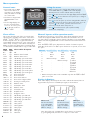
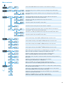
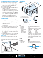
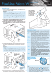
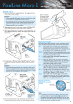
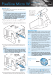
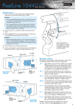
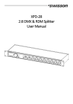
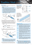
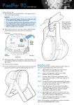
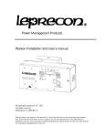
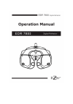
PixelLine Micro W Version 1.01 firmware User Manual General set up 1 Mount the fixture in the required position. The integral yoke can act as a floor stand or hanger. Important • When suspended off ground, always use a safety wire rated to a minimum of 11kg (25lbs) around the yoke. • Do not position the fixture close to fog machines. The fog oil mist will be drawn in by the cooling fan and will short out important components. The warranty will be void for all fixtures returned in such a condition. When suspended off ground, always use a safety wire rated to a minimum of 11kg (25lbs) around the yoke 2 Where external control is to be used, connect a DMX lead (XLR 5-pin female) to the input socket at the rear of the fixture. 3 Where other fixtures are to be used in a control daisy-chain, connect a DMX lead (XLR 5-pin male) to the output socket at the rear of the fixture. DMX out (XLR 5pin female) socket Operation modes UP N W DO R TE EN U N ME om ruct e.c inst ng ting lra opera ixe roper w.p al for p ww *R efe r to pro du ct ma s ion The PixelLine Micro Wash fixture provides a range of operation modes. These are selected using the MODE section of the control menu: nu DMX Allows RGBA control via DMX input. Using the RES (resolution) option you can determine the number of DMX channels required: either 3 or 4 channels. In 3 channel mode, the red and amber channels are combined, whereas in 4 channel mode, the red and amber channels are controlled separately. Internal chase effects are not available within this mode. MANU Provides RGBA colour mixing independently of any external control. Use the internal control menu (MAN section) to select the required colour values. EF M Allows the display of the dual internal chase effects, independently of any external control. Use the internal control menu (PROG section) to select the required chase effects, speeds and cross fades. 4+E Provides control of RGBA mixing and selection of the dual internal chase effects via DMX input. Requires 11 DMX channels. DMX in (XLR 5pin male) socket 4 Connect power to the fixture using a Neutrik® PowerCon® connector. Insert the connector and twist it clockwise until it clicks into place. Important • When daisy-chaining fixtures, do not exceed a total load of 3kW in a single daisy chain (subject to supply and cabling restrictions). Maximum power requirements per fixture: Micro Wash units - 66 watts. See also the ‘Start up (peak)’ note on page 4. PixelLine Micro fixture personalities are available for a variety of controllers. Please see www.pixelrange.com for details. Power out socket (Neutrik® PowerCon® NAC3FCB connector required) UP Neutrik® PowerCon® (NAC3FCA) connector wiring N W Neutral DO R TE EN NU ME ix rop w.p al for p ww e *R fer ns om ructio e.c ting inst ng a elr to pro du ct ma er e op Live N L ra nu Earth Fuse holder (on underside, see page 4 for details) Power in socket Note Neutrik® PowerCon® (NAC3FCA) connector 5 Use the control panel to access the internal menu and choose the appropriate operation mode and related settings (see over). • To optionally clear all previous settings: At the rear panel, press the middle two buttons ( and ) while the DMX address is displayed (e.g. A001, A002, etc). The four digit display will show FACT then SET to indicate that the fixture has been returned to its default condition. Menu operation General notes Using the menu • Ensure that only one DMX • When not in the menu, the four digit display shows the device in the chain is set as master (e.g. the lighting desk). This fixture is usually set to slave mode. • This fixture is shipped with the DMX address set to 001. • The four digit display can be set to switch off when not in use. To restore, press . To alter this mode use: PERS > DISP. ENTER DOWN UP www.pixelrange.com *Refer to product manual for proper operating instructions to enter the menu. The four digit display will show ADDR. • Press and to move between menu options (or to change a • Use value within an option). to enter an option (or to fix a changed value within an • Press option and return to the previous option level). Note: If you do not press to fix a value, operation will revert to the previously set mode at the next power on. to exit from a menu option (and eventually • Press exit the menu completely). Chase effects Channel layouts within operation modes This section describes each of the 31 internal chase effects that are selectable either via the control menu (prog > c1/c2 > EFEC) or using DMX values sent from an external source. To use the internal effects, set the mode option either to ef m (to control effects via the menu) or 4+E (to control effects externally via DMX). See page 4 for details about controlling effects on other fixtures via DMX without using a control desk. The table below shows how colour mixing, chase effects and master intensity controls are mapped to DMX channels for each mode. Mode dmx does not use chase effects. In all modes, the first channel of the fixture occurs at the DMX address selected using addr and successive channels for the fixture follow from there. DMX value MENU current DMX address e.g. A001. Some of the display’s decimal points are used to indicate status (see below). EFEC value Chase effect description 0-7 00 Off 8-15 01 Rainbow chase forward 16-23 02 Rainbow chase reverse 24-31 03 10/90 duty cycle strobe white 32-39 04 10/90 duty cycle strobe white 40-47 05 10/90 duty cycle strobe white 48-55 06 50/50 duty cycle strobe white 56-63 07 50/50 duty cycle strobe red 64-71 08 50/50 duty cycle strobe blue 72-79 09 50/50 duty cycle strobe yellow 80-87 10 50/50 duty cycle strobe green 88-95 11 Pulse strobe white 96-103 12 Pulse strobe blue 104-111 13 Pulse strobe rainbow 112-119 14 Pulse strobe red/green/blue 120-127 15 Primary/secondary chase 128-135 16 Rainbow chase 136-143 17 Yellow/blue chase 144-151 18 Rainbow chase 152-159 19 Yellow/blue chase 160-167 20 Red/blue chase 168-175 21 Red/green chase 176-183 22 50/50 duty cycle fade red 184-191 23 50/50 duty cycle fade green 192-199 24 50/50 duty cycle fade blue 200-207 25 Static orange 208-215 26 Static yellow 216-223 27 Static light blue 224-231 28 Static purple 232-239 29 Static red 240-247 30 Static green 248-255 31 Static blue Note: The PERS > RES option determines the number of channels required within DMX mode. There is a 16BT option which does not operate, do not select this option. Channel dmX (RES=3CH)) dmX (RES=4CH) 4+E (Wash) 1 Red Red Red 2 Green Green Green 3 Blue Blue Blue 4 Master intensity* Amber Amber 5 - Master intensity* c1 Effect 6 - - c1 Speed 7 - - c1 Xfade 8 - - c2 Effect 9 - - c2 Speed 10 - - c2 Xfade 11 - - Master int. * Master intensity for dmx mode is available only when the pers > mint option is set to on. Display indications Three of the display’s decimal points are used to indicate the master/slave settings and also the presence of a DMX input signal, as shown below: Master mode Slave mode DMX input On when the fixture is set within master mode. Use PERS > data to change. On when the fixture is set within slave mode. Use PERS > data to change. Flashes when a valid DMX input signal is detected. Note: Ensure that only one DMX device in the chain is set as master (e.g. the lighting desk). This fixture is usually set to slave mode. Menu contents Sets the base DMX address from which the control channels will begin. Shows the main processor software revision. No changes are possible within this option. Shows the display controller software revision. No changes are possible within this option. Selects the primary internal chase effect. See Chase effects for descriptions. Select mode > ef m to show the selected chase. Selects the cross fade speed between the steps of the selected c1 chase effect. Selects the speed of the selected c1 chase effect. Selects the secondary internal chase effect. See Chase effects for descriptions. Select mode > ef m to show the selected chase. Selects the cross fade speed between the steps of the selected c2 chase effect. Selects the speed of the selected c2 chase effect. Sets the red intensity. Select mode > manu (manual) to show the result. Sets the amber intensity. Select mode > manu (manual) to show the result. Sets the blue intensity. Select mode > manu (manual) to show the result. Sets the green intensity. Select mode > manu (manual) to show the result. (Affects DMX mode only) Determines how DMX channels are assigned to colours. Options are 3CH (red & amber combined), 4CH &16bT (do not use). Determines whether this fixture will act as a master controlling others. When controlled by DMX input, this fixture must be set to slav. Affects dmx mode only. When set on this enables the master intensity channel for dmx mode. Selects the master intensity level of chase effects c1 and c2. Determines the intensity of the four digit control panel display. Values range from 0 (dimmest) to 15 (brightest). When set to Aoff, the control panel display will blank out shortly after the menu is exited. The DMX signal indications will remain active. RGB control using three DMX channels. mint set to on provides a master intensity. No chase effects are selectable. Displays the resulting RGB levels that are set via the man section of the internal menu. External DMX control is not possible in this mode. Displays the chase effect(s) determined within the prog section. External DMX control is not possible in this mode. DMX Ch1 to 4: RGBA, Ch5 to 7: c1 Effect, Speed & Xfade, Ch8 to 10: c2 Effect, Speed & Xfade, Ch11: Master intensity. Using master mode to drive other units This unit can control any number of other Pixel Range fixtures via DMX links, without the need for a control desk. Specifications Dimensions 1 Set this unit as master (PERS > DATA > MAST) and ensure all others are set to slave (PERS > DATA > SLAV). Connect all fixtures via DMX daisy-chain. 16 7m (6 1/ m 2” ) m 3m 20 ”) (8 2 Set each slave to Mode > DMX. 3 Set each slave DMX address (using ADDR > DMX) according to the following: mm 863 ”) /8 (3 18 cells are output in groups of 3 DMX channels to give RGB values per cell (54 channels in total). Set the address of each slave fixture according to which of the 18 cells you want them to appear within, or to begin with (for multi-cell fixtures): (A001 for cell 1, A004 for cell 2, ... A052 for cell 18). Set RGBA slave fixtures to 3 channel mode (using PERS > RES > 3ch). 4 Set the master to Mode > EF m (the master unit’s DMX address is ignored). On the master, choose the required effects to display and send to the slave fixtures using PROG > C1 and C2. Note: The dimensions shown above relate to the main fixture body. The yoke knob extends 10mm (3/8”) beyond the stated width of the fixture. Troubleshooting 150mm (5 7/8 ”) Fixture remains at blackout when illumination expected • The display panel (or at least one of its decimal points) should be lit - if not, check the input power and fuse. 110mm (4 1/3 ") • If live DMX is connected, the right hand decimal point on the display should flash - if not, check the DMX cable and the desk output. Weight Fixture and yoke: • Check that the selected MODE matches the desk personality being used. 2.1Kg (4.6lbs) Power • The master intensity channel for the current mode may be set at zero. For DMX mode, check the setting of PERS > MINT. • Ensure that only one DMX device is set as master. • Standalone chase effects: Effects programmed using PROG > C1 and C2 but the fixture is not in MODE > EF M mode. Check also that MODE > PROG > LEVL is not set at zero. Input voltage: 90 to 264V AC, 47 to 63Hz autosensing Earth leakage 0.12mA Connectors: Neutrik® PowerCon® (see first page for details) Power requirements: @ 230V/50Hz 2 watts 2 watts Maximum (const.) 66 watts 66 watts Start up (peak*) <40 amps <20 amps • Standalone RGB mixing: Colour values set within MAN section but the fixture is not in MODE > MANU mode. * The peak value occurs only at first power up and lasts only for a period measured in microseconds. Adjustments may need to be made to supply circuit breakers when multiple fixtures are daisy-chained, causing them all to draw the peak simultaneously. Fuse access The single fuse is located on the underside panel of the fixture. To remove the fuse Using a flatblade screwdriver, push down the fuse cap and then twist it anti-clockwise until it disengages from the holder. @ 115V/60Hz Standby Approvals Miscellaneous Fuse type: 20mm 2A (T2AH) anti-surge, ceramic body Enclosure rating: IP20 (not protected against moisture ingress) Control input: USITT DMX512 (input connector pin out below) PIN 1 PIN 5 Ground Not used PIN 2 PIN 4 Data – Not used PIN 3 Data + Documentation by Corporate Text & Design (www.ctxd.com) Release 1.01e UK +44 (0)1905 363600 [email protected] www.pixelrange.com USA +1 865 675 3955 [email protected]