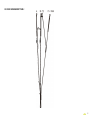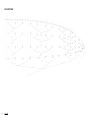
1
USER’S
MANUAL
Graceful in flight
PEAK 2
WELCOME
We wish to welcome you to our team and thank you for the confidence, which
you have placed in a NIVIUK Glider.
The ALL NEW PEAK 2 is not simply an update of the original PEAK, it is a
totally new glider designed and created using the unique Niviuk philosophy
and from a clean drawing board. With a new highly efficient line plan, a new
profile and a new AR of 6.7 it brings with it a higher range of speed, a more
efficient climb rate and an improved glide ratio. The PEAK was a very hard
act to follow but with each new detail the PEAK 2 has done just that.
We are sure that you will enjoy flying this wing and that you will soon find out
the true meaning of our slogan:
“Give importance to the small details to make big things happen”
This is the user manual, which we recommend you take time to read in
detail.
The NIVIUK Gliders Team.
NIVIUK Gliders C/ Doctor Codina, 29 bajos 17165 La Cellera de Ter Girona - SPAIN
Tel. +34 972 42 28 78 Fax +34 972 42 00 86
[email protected] www.niviuk.com
2
USER’S MANUAL
NIVIUK Gliders PEAK 2
This manual offers all the necessary information that will familiarize you with
the main characteristics of your new paraglider. Although this manual informs
you about your glider, it does not offer the instruction requirements necessary
for you to be able to pilot this type of wing. Flying instruction can only be
taught at a paragliding school recognised by the Flying Federation of your
country.
Nevertheless we remind you that it is important that you carefully read all the
contents of the manual for your new PEAK 2 glider.
Severe injuries to the pilot can be the consequence of the misuse of this
equipment.
SUMMARY
WELCOME
2
5.1 BIG EARS
10
USER’S MANUAL
2
5.2 B-LINE STALL
11
1. CHARACTERISTICS
4
5.3 SPIRAL DIVE
11
1.1 WHO IS IT DESIGNED FOR?
4
6. SPECIAL METHODS
11
1.2 CERTIFICATION
4
6.1 TOWING
11
1.3 IN-FLIGHT BEHAVIOUR
4
6.2 ACROBATIC FLIGHT
11
1.4 ASSEMBLY, MATERIALS
4
7. FOLDING INSTRUCTIONS
12
1.5 ELEMENTS, COMPONENTS
5
8. CARE AND MAINTENANCE
12
2. UNPACKING AND ASSEMBLY
5
8.1 MAINTENANCE
12
2.1 CHOOSE THE RIGHT PLACE
5
8.2 STORAGE
12
2.2 PROCEDURE
6
8.3 CHECKS AND CONTROLS
12
2.3 ASSEMBLY OF THE HARNESS
6
8.4 REPAIRS
12
2.4 TYPE OF HARNESS
6
9. SAFETY AND RESPONSIBILITY
13
2.5 ASSEMBLY OF THE ACCELERATOR
6
10. GUARANTEE
13
11. TECHNICAL DATA
14
2.6 INSPECTION AND WING INFLATION ON
THE GROUND
6
10.1 TECHNICAL DATA
14
2.7 ADJUSTING THE BRAKES
6
10.2 MATERIALS DESCRIPTION
14
3. THE FIRST FLIGHT
7
10.3 RISER ARRANGEMENT
15
3.1 CHOOSE THE RIGHT PLACE
7
10.4 LINE PLAN
16
3.2 PREPARATION
7
10.5 DIMENSIONS PEAK 2 22
17
3.3 FLIGHT PLAN
7
10.6 DIMENSIONS PEAK 2 24
17
3.4 PRE-FLIGHT CHECK LIST
7
10.7 DIMENSIONS PEAK 2 26
18
10.8 DIMENSIONS PEAK 2 28
18
10.9 CERTIFICATION SPECIMEN
19
3.5 WING INFLATION, CONTROL, AND
TAKE-OFF
7
3.6 LANDING
7
4. IN FLIGHT
7
4.1 FLYING IN TURBULENCE
7
4.2 POSSIBLE CONFIGURATIONS
8
4.3 USING THE ACCELERATOR
9
4.4 FLYING WITHOUT BRAKE LINES
9
4.5 KNOTS IN FLIGHT
10
5. LOSING HEIGHT
10
3
1. CHARACTERISTICS
1.1 WHO IS IT DESIGNED FOR?
The PEAK 2 has been designed for current and experienced pilots and those
wishing to compete in high performance competitions but without renouncing
the security of a certified glider. The PEAK 2 has been particularly designed
for the serious Cross Country enthusiast who seeks the performance,
confidence and comfort, to be able to maximise and fully enjoy his/her flights.
1.2 CERTIFICATION
The PEAK 2 has successfully achieved the European EN certification. All the
commercially available sizes passed every required test with excellent results
and the PEAK 2 received the D certification for all the sizes.
The PEAK 2 passed the essential load test of 8 g without experiencing any
problems. This test was carried out in the Swiss Air-Turquoise laboratories in
Switzerland.
Check the homologation results and figures on the last pages of this manual.
1.3 IN-FLIGHT BEHAVIOUR
The PEAK 2 carries the very unique Niviuk design DNA and has been
created to achieve optimum performance, maximum safety and maximum
pilot potential. Niviuk understands the sport of paragliding and the reasons
why every pilot feels the need to fly the PEAK 2 is a glider for both. Our
objective was to give the pilot a glider which not only offers a pure flying
sensation but above all, a glider which is in complete harmony with the pilot,
passing clear precise information and by doing so offering a perfect analysis
of the air mass. Experience the perfect fusion of performance and grace,
maximise your potential, fly the PEAK 2.
In thermals, the PEAK 2 displays its superior efficiency, one way above
other gliders in the same class. For those who are not used to flying with
an aspect ratio of 6.7 and three rows of lines, turning may require a little
adaptation time but once you know how, you will enjoy precise piloting with
an active response to your demands. The PEAK 2 will very quickly inspire
you with confidence and place you on top of the thermal stack, enjoying the
performance, efficiency and speed.
The glide ratio and the speed range of the PEAK 2 can only be described
as outstanding. The PEAK 2 allows the pilot to accurately feel and asses the
information given by the glider and to anticipate every movement, even at high
speed where the glider remains solid and communicative. The speed system
is both smooth and progressive and when the application of the first half of
the accelerator is applied you will feel a real sense of acceleration without
experiencing huge sink. The second half provides pure and increasing speed
to the maximum level, depending on the air mass at the time.
1.4 ASSEMBLY, MATERIALS
The PEAK 2 has all the technological innovations as used on other NIVIUK
gliders. Furthermore attention to small details such as the use Harken pulleys
and very small pulleys on the risers have been used to improve the comfort
and efficiency of the speed system. No more tired and aching legs.
The use of the SLE (Structured Leading Edge) allows reinforcement of the
leading edge preventing any deformation during turbulence. The airflow is
also vastly improved over the entire front span of the glider.
The new generation profile has been conceived to efficiently distribute the
total load across the three rows of lines. The chosen materials and line
dimensions have minimum air resistance while respecting the security and
maximum load efficiency.
Also, a new technology developed from the competition prototypes has been
adapted to the Peak 2, the new STE (Structured Trailing Edge).
4
STE is based on the leading technology we use for the Icepeak 4 NS. It
optimises the profile without deforming it. We can thus obtain less resistance
and better performance. With the STE, the circulation of the air is more fluid,
maintaining a consistent airflow at the trailing edge, and obtaining a cleaner
airflow at high speeds. The pitch control is notably improved as well. STE
works on more surface of the wing without distorting the profile.
We use on the Peak 2 lines of great performance so it is necessary that
ALL lines are thoroughly checked every 100 hours or every 6 months. The
fabrics used for the glider have been very carefully selected for its lightweight,
resilience under normal conditions and UV standards.
Not a single millimetre of error is possible in the manufacturing process from
Olivier’s computer to the cutting of the fabric. The cutting is done section by
section in an extremely meticulous manner. The numbering and marking
of the guideline marks is also done in the same meticulous way so avoiding
errors in this critical process.
Information about construction materials is given on the last pages of this
manual.
1.5ELEMENTS, COMPONENTS
The PEAK 2 is delivered to its owner together with a series of components
that, although not fundamental, do take an important part in the use,
transport and storage of the paraglider. The glider is delivered together with a
rucksack, large enough for all of the equipment to fit inside (195 liters), once
appropriately packed. The rucksack is designed to make transport on foot as
pleasant as possible. The internal bag, intended to protect the PEAK 2 from
possible damage, during storage is also supplied.
The compression strap allows you to keep the glider as good as possible in
the rucksack. Furthermore you will find the accelerator bar that completes
the acceleration gear of the wing, a small fabric repair kit made of autoadhesive ripstop and a user’s manual with the answers all our questions
about our new PEAK 2.
The lines are semi-automatically manufactured and all the sewing is finished
under the supervision of our specialists.
2.UNPACKING AND ASSEMBLY
The jigsaw puzzle of the assembly process is made easier using this method.
We economize on resources while making the quality control more efficient.
All the different parts of the canopy are cut and assembled under the strict
conditions induced by the automation of the whole process.
All NIVIUK Gliders go through an extremely thorough and efficient final
inspection. Every single line of each glider is measured individually once the
final assembly has concluded.
Each wing is thoroughly inspected at the end of it assembly. Each glider
is packaged following the maintenance and conservation instructions
recommended for the advanced materials. NIVIUK Gliders are made of
first class materials as demanded by the performance, durability, and
homologation requirements of the present-day market.
2.1 CHOOSE THE RIGHT PLACE
We recommend that you unpack and assemble your wing on a schooling
slope or a flat clear area without to much wind and free of obstacles. These
conditions will allow you to carry out all the steps required for you to check
and inflate the NIVIUK PEAK 2.
We recommend that an instructor or a retailer supervise the entire procedure,
as only they are competent to resolve any doubt in a safe and professional way.
5
2.2 PROCEDURE
2.5 ASSEMBLY OF THE ACCELERATOR
Take the paraglider out of the rucksack, open it and spread it open with the
lines on top of the underside, position the wing as if you were to inflate it.
Check the condition of the fabric and the lines, making sure there are no
abnormalities. Check the maillons, which attach the lines to the risers, are
properly closed. Identify and if necessary disentangle the lines from A, B, and
C risers, the brake lines and the corresponding risers. Make sure that there
are no ties or knots.
The acceleration mechanism of the PEAK 2 works when you push with your
feet on the accelerator bar, this is supplied with the equipment. On delivery
the accelerator bar has not yet been installed and it is recommended that it
is fit by your self before flight. Most harnesses are equipped with a preinstalled acceleration system. When fitting any accelerator system ensure
that all preinstalled items within the harness, such as roller pulleys are used
correctly. After fitting, take into account that you will have to adjust the length
of the accelerator lines for correct use. This will vary according to the length
of the pilot’s legs!
We recommend that you try the correct fitting of the acceleration system on
equipment designed to do this, most paragliding schools have this sort of
equipment.
2.3 ASSEMBLY OF THE HARNESS
Correctly place the risers on the harness karabiners. The risers and lines
should not have any twists and they should be in the right order. Check that
the harness buckles are correctly locked.
2.6 INSPECTION AND WING INFLATION ON THE GROUND
2.4 TYPE OF HARNESS
The PEAK 2 has passed the EN D certification using an ABS type harness.
This certification allows it to be flown with most of the harnesses on the
market. We strongly recommend that you adjust the distance of the chest
strap according the values used during certification. This varies according to
the size of the chosen harness.
Small = 44 cm
Medium = 45 cm
Large = 46 cm
Once you have checked all the equipment and made sure that the wind
conditions are favourable, inflate your PEAK 2 as many times as necessary in
order to become acquainted with the wing’s behaviour. The PEAK 2 inflates
easily and smoothly. An excess of energy is not necessary and the wing will
inflate with minimum pressure on the harness when you move forward. This
may be assisted by using the A lines. Do not pull on them; just accompany
the natural rising movement of the wing. Once the wing is in the 12 o’clock
position, simply apply correct pressure on the brake lines and the PEAK will
sit over your head.
2.7 ADJUSTING THE BRAKES
Any changes made to these specifications may affect the wing’s performance
and reactions. This would therefore effect the glider’s configuration and
would not conform to the certification.
6
The length of the main brake lines is adjusted at the factory to the length
established during certification. However, the length can be changed to
adapt to the pilot’s flying style. Nevertheless, we recommend that you fly for
a while with these, set at the original length. This will allow you to become
accustomed to the PEAK 2 and it’s unique flying behaviour. If you then
decide to change the length of the brake lines, untie the knot, slide the line
through the brake link to the desired length, and strongly re-tie the knot.
Qualified personnel should carry out this adjustment. You must ensure that
this adjustment does not slow down the glider without any pilot input. Both
brake lines should be symmetrical and measure the same length. The most
recommended knots are the clove hitch knot or bowline knot.
3. THE FIRST FLIGHT
inflation phase is carried out without anguish. These take off characteristics
provide a perfect control phase and enough time for the pilot to decide
whether to accelerate and take off.
Whenever the wind speed allows it, we recommend a reverse launch
technique, this type of launch allows you to carry out a better visual check of
the wing. The PEAK 2 is especially easy to control in this position in strong
winds. However, wind speeds up to 25 to 30 km/h are considered strong and
extra consideration should be given to any thought of flight.
3.1 CHOOSE THE RIGHT PLACE
We recommend that the first flight with your PEAK 2 is made on a smooth
slope (a school slope) or in your usual flying area.
Preparation and positioning of the wing on the take off is especially important.
Choose a location, which is appropriate for the direction of the wind. Position
the paraglider as if it were part of a large circle, taking into account the shape
of the canopy in flight. All this will assist in a trouble free take-off.
3.2 PREPARATION
3.6 LANDING
Repeat the procedures detailed in chapter 2 (UNPACKING AND ASSEMBLY)
in order to prepare your PEAK 2.
3.3 FLIGHT PLAN
The PEAK 2 lands excellently, it transforms the wing speed into lift on the
pilot’s demand, allowing an enormous margin of error. You will not have to
wrap the brake lines around your hand to get greater braking efficiency.
Draw out a flight plan before take-off in order to avoid possible flight errors.
4. IN FLIGHT
3.4 PRE-FLIGHT CHECK LIST
4.1 FLYING IN TURBULENCE
Once you are ready, but before you take-off, carry out another equipment
inspection. Ensure correct installation of all equipment and that all lines are
free of hindrances or knots. Check that the weather conditions are suited for
your flying skills.
3.5 WING INFLATION, CONTROL, AND TAKE-OFF
The PEAK 2 has an excellent profile to withstand the very different aerological conditions so allowing the best possible piloting and stability. It reacts
admirably in passive flight, thus offering a high level of safety in turbulent
conditions. Nonetheless, the pilot always has to pilot according to the
prevailing weather conditions, the pilot is the ultimate safety factor.
Smoothly and progressively inflate the wing (chapter 2.6 INSPECTION AND
WING INFLATION ON THE GROUND). The PEAK 2 inflates easily and does
not require excessive energy. It does not tend to over-take you, so the wing
We recommend active piloting, making the necessary fine adjustments to
keep the wing in control. He/she should stop braking to allow it to fly at
the required wing speed after a correction is made. Do not maintain any
7
correction for longer than necessary (braked) this would cause the wing to
enter into critical flying situation. Whenever necessary, control a situation,
react to it and then re-establish the required speed.
4.2 POSSIBLE CONFIGURATIONS
We recommend that training to master these manoeuvres be carried out
under the supervision of a competent school.
Asymmetric collapse
In spite of the great stability of the profile of the PEAK 2, heavy turbulent
conditions may cause part of the wing to collapse asymmetrically. This
usually happens when the pilot has not foreseen this possible reaction of
the wing. When the wing is about to experience an asymmetric collapse the
brake lines and the harness will transmit a loss of pressure to the pilot. To
prevent the collapse from happening, pull the brake line corresponding to the
compromised side of the wing, this will increase the angle of incidence. If the
collapse does happen the PEAK 2 will not react violently, the turn tendency is
very gradual and it is easily controlled. Lean your body towards the side that
is still flying in order to counteract the turn and to maintain a straight course,
if necessary slightly slow down the same side. The collapse will normally open
by itself but if that does not happen, pull completely on the brake line on the
side, which has collapsed (100%). Do this with a firm movement. You may
have to repeat this operation to provoke the re-opening. Take care not to overbrake on the side that is still flying (turn control) and when the collapse has
been solved; remember to let the wing recover its flying speed.
Symmetric collapse
In normal flying conditions the design of the PEAK 2 ensures that a
symmetric collapse is quite improbable. The profile of the wing has been
designed to widely tolerate extreme changes in the angle of incidence. A
symmetric collapse may occur in heavy turbulent conditions, on entry or
exit of strong thermals or lack of adapting the use of the accelerator to the
prevailing air conditions. Symmetrical collapses usually re-inflate without the
glider turning but you can symmetrically apply the brake lines with a quick
8
deep pump to quicken the re-inflation. Release the brake lines immediately
to recover optimum flight speed.
Negative spin
This configuration is out of the normal flight behaviour of the PEAK 2. Certain
circumstances however, may provoke this configuration such as trying to turn
when the wing is flying at very low speed (while heavily braking). It is not easy
to give any recommendations about this situation since it varies depending
on the circumstances. Remember that you should restore the relative air
speed over the wing. To achieve this, progressively reduce the pressure on
the brake lines and let the wing gain speed. The normal reaction would be
a lateral surge with a turn tendency no greater than 360º before restoring to
normal flight conditions.
Parachutal stall
If it does happen, the feeling would be that the wing would not be advancing;
you would feel a kind of instability and a lack of pressure on the brake lines,
although the canopy would appear to be correctly inflated. The correct
reaction would be to release the pressure on the brake lines and push the A
lines forward or rather lean your body to any side WITHOUT PULLING ON
THE BRAKE LINES.
Deep stall
The possibility of the PEAK 2 falling into this configuration during normal flight is
very unlikely. This could happen if you are flying at a very low speed, whilst over
steering in a number of manoeuvres and in turbulent conditions. To provoke a
deep stall you have to take the wing to minimum flight speed by symmetrically
pulling the brake lines, when you reach this point, continue pulling until you
reach 100% and then hold. The glider will first fall behind you and then situate
itself above you, rocking slightly, depending on how the manoeuvre was carried
out. When you start to provoke a stall, be positive and do not doubt an instant.
Do not release the brake lines when half way through the manoeuvre. This
would cause the glider to surge violently forward with great energy and may
result in the wing below the pilot. It is very important that the pressure on the
brake lines is maintained until the wing is well established vertical above.
To regain normal flight conditions, progressively and symmetrically release
the brake lines, letting the speed be re-established. When the wing reaches
the maximum advanced position ensure that the brakes are fully released.
The wing will now surge forward, this is necessary so that air speed is
completely restored over the wing. Do not over brake at this point because
the wing needs to recover speed to quit the stall configuration. If you have to
control a possible symmetrical front stall, briefly and symmetrically pull on the
brake lines and let go even when the wing is still ahead of you.
Wing tangle
A wing tangle may happen after an asymmetric collapse, the end of the wing
is trapped between the lines (Cravat). This situation could rapidly cause the
wing to turn, although it depends on the nature of the tangle. The correction
manoeuvres are the same as those applied in the case of an asymmetrical
collapse, control the turn tendency by applying the opposite brake and lean
your body against the turn. Then locate the line that reaches the stabiliser
that is trapped between the other lines. This line has a different colour and
belongs to the external lines of the C riser.
Pull on this line until it is tense, this should help to undo the wing tangle. If
you cannot undo the tangle, fly to the nearest possible landing spot, control
the flying course with your body movements and a little pressure on the
opposite brake. Be careful when attempting to undo a tangle if you are flying
near a mountainside or near to other paragliders, you may lose control of the
flying course and a collision may occur.
Over handling
Most flying incidents are caused by incorrect actions of the pilot, which
chained one after another creates abnormal flying configurations (a cascade
of incidents). You must to remember that over handling the wing will lead to
critical levels of functioning. The PEAK 2 is designed always to try to recover
normal flight by itself, do not try to over handle it.
continues to over handle. You have to allow the profile to re-establish normal
flight speed after any type of handling.
4.3 USING THE ACCELERATOR
The profile of the PEAK 2 has been designed to fly stable through its
entire speed range. It is useful to accelerate when flying in strong winds
or in extreme descending air. When you accelerate the wing, the profile
becomes more sensitive to possible turbulence and closer to a possible
frontal collapse. If you feel a pressure loss, you should release the pressure
on the accelerator and pull slightly on the brake lines to increase the angle
of incidence. Remember that you have to re-establish the flight speed after
correcting the incidence.
It is NOT recommended to accelerate near to the mountainside or in very
turbulent conditions. If necessary you will have to constantly adjust the
movements and pressure on the accelerator whilst constantly adjusting the
pressure applied to the brake lines. This balance is considered to be “active
piloting.”
4.4 FLYING WITHOUT BRAKE LINES
If, for any reason at all, you cannot use the brake lines of your PEAK 2 you
will have to pilot the wing using the C-risers and your body weight to fly
towards the nearest landing. The C-lines steer easily because they are not
under pressure, you have to be careful not to over handle them causing a
stall or negative turn. To land you have to let the wing fly at full speed and
before reaching the ground you will have to pull symmetrically on both the
C-risers. This braking method is not as effective as using the brake lines so
you will land at a higher speed.
Generally speaking, the reactions of the wing, which follow over handling, are
neither due to the input made or the intensity, but the length of time the pilot
9
4.5 KNOTS IN FLIGHT
The best way to avoid these knots and tangles is to inspect the lines
before you inflate the wing for take-off. If you notice a knot before take off,
immediately stop running and do not take-off.
If you have taken-off with a knot you will have to correct the drift by leaning
on the opposite side of the knot and apply the brake line on that side too. You
can gently try to pull on the brake line to see if the knot becomes unfastened
or try to identify the line with the knot in it. Try to pull the identified line to
see if the knot undoes. Be very careful when trying to remove a knot. When
there are knots in the lines or when they are tangled, do not pull too hard on
the brake lines because there is an increased risk of the wing to stalling or
negative turn being initiated
Before trying to remove a knot, make sure there are no pilots flying nearby and
never try these manoeuvres near the mountainside. If the knot is too tight and
you cannot remove it, carefully and safely fly to the nearest landing place.
5. LOSING HEIGHT
The knowledge of the different descent techniques is an important resource
to use in certain situations. The most adequate descent method will depend
on the particular situation.
We recommend that you learn to use these manoeuvres under the tuition of a
competent school.
5.1 EARS
Big ears are a moderate descent method, reaching –3 or –4 m/s, ground
speed reduces slightly between 3 and 5 km/h and piloting becomes limited.
The angle of incidence and the surface wing load also increases. Push on the
accelerator to restore the wing’s horizontal speed and the angle of incidence.
10
To pull big ears take the outermost A-lines of both stabilizers as high up as
possible and pull on them outward and downward. The wingtips will fold in.
Let go of the lines and the big ears will re-inflate automatically. If they do not
re-inflate, gently pull on one of the brake lines and then on the opposite one.
We recommend that you re-inflate asymmetrically, not to alter the angle of
incidence, more so if you are flying near the ground or flying in turbulence.
Please, read this carefully: Risk of full stall!!!
As can be seen on the EN Certification, the PEAK 2 has a relatively short
brake travel and it should be noted that by reaching for the A3 line to make
big ears it is possible to apply brake pressure without realising it. The same
happens whilst pulling down the A3 line to make the ears. This can obviously
lead to a significant speed decrease.
The PEAK 2 has a new high arch concept and applying ears induces more
resistance. With this new arch, the ears don’t stick but they do tend to
“hang”. Because of this, there will be more resistance, compared to ears on a
standard glider.
Because of the design concept, the PEAK 2 has a low transverse tension,
which results in less pitch. This is good in normal conditions however on the
other hand the glider could get into trouble if it is allowed pitch and achieve
an extreme angle of incidence.
These are 3 particularities, which together with turbulent conditions could
cause an unintentional stall.
The Solution: Big ears may still be applied but the pilot must be fully aware
of the above-mentioned points and act accordingly. To avoid the stall simply
use the accelerator halfway (this is sufficient) to increase the speed, which
naturally decreases the angle of incidence. In this way you will maintain a
safe margin and avoid this phenomenon.
Take care not to pull the brakes while making the ears !!
Some pilots would say: “Nothing is better than a good descending air mass to
descend safely!!!”
To start the manoeuvre, first lean your bodyweight and pull the brake line to
the side to which you are leaning. You can regulate the intensity of the turn
by applying a little outside brake.
5.2 B-LINE STALL
When you carry out this manoeuvre, the wing stops flying, it loses all
horizontal speed and you are not in control of the paraglider. The air
circulation over the profile is interrupted and the wing enters into a situation
similar to parachuting.
To carry out this manoeuvre you have to take the B-risers below the maillons
and symmetrically pull both of them down (approx. 20-30 cms) and then
hold this position. The initial phase is quite physical (hard resistance)
which means that you will have to pull strongly until the profile of the wing
is deformed, when this happens the required force will then significantly
reduce. To maintain this manoeuvre you must continue to hold the B Lines
in the pulled down position. The wing will then become deformed, horizontal
speed drops to 0 km/h and vertical speed increases to –6 to –8 m/s
depending on the conditions and how the manoeuvre has been performed.
To exit the manoeuvre, simultaneously release both risers, the wing will then
slightly surge forward and then automatically return to normal flight. It is better
to let go of the lines quickly rather than slowly. This is an easy manoeuvre but
you must remember that the wing stops flying, it loses all horizontal movement
and its reactions are very different compared to normal flight.
5.3 SPIRAL DIVE
This is a more effective way for rapidly losing height. You have to know that,
the wing can gain a lot of speed and the increase in G’s will be substantial.
This can cause a loss of orientation and consciousness (blackouts). These
are the reasons why it is best to carry out this manoeuvre gradually so your
capacity to resist the G forces increases and you will learn to fully appreciate
and understand the manoeuvre. Always practice this manoeuvre when flying
at high altitude.
A paraglider flying at its maximum turn speed can reach –20 m/s, equivalent
70 km/h vertical speed and stabilize in a spiral dive from 15 m/s onwards.
These are the reasons why you should be familiar with the manoeuvre and
know how to carry out the exit methods.
To exit this manoeuvre you must progressively release the inside brake and
also momentarily apply outside brake. Whilst doing this you must also lean
your bodyweight towards the outside. This exit manoeuvre has to be carried
out gradually and with smooth movements so you can feel the pressure and
speed changes at the same time.
The after effect of the exit manoeuvre is that the glider will rock briefly with
lateral surge, depending on how the manoeuvre has been carried out.
Practice these movements at sufficient altitude and with moderation.
6. SPECIAL METHODS
6.1 TOWING
The PEAK 2 does not experience any problem whilst being towed. Only
qualified personnel should handle the qualified equipment to carry out this
operation. The wing has to be inflated in the same way as in normal flight.
6.2 ACROBATIC FLIGHT
Although the PEAK 2 has been tested by expert acrobatic pilots in extreme
situations, it HAS NOT been designed for acrobatic flight and we DO
NOT RECOMMEND THE USE OF THIS GLIDER for that use. We consider
acrobatic flight to be any form of piloting that is different to normal flight. To
learn safely how to master acrobatic manoeuvres you should attend lessons,
11
which are carried out and supervised by a qualified instructor over water.
Extreme manoeuvres take you and your wing to centrifugal forces that can
reach 4 to 5 g. Materials will wear more quickly than in normal flight.
7. FOLDING INSTRUCTIONS
The PEAK 2 has a complex leading and trailing edge, manufactured using
a variety of different materials. For that reason, the use of a correct folding
method is very important for extending the useful life of your paraglider. It
should be folded like an accordion, with the leading edge reinforcements flat
and the rigifoils positioned one upon the other. This method will ensure that
the profile remains in good shape without altering its form or its performance.
The wing should then be folded in three parts taking care of not bending
or twisting the STE or the SLE rigifoils. The wing does not have to be tightly
folded, if you do so it may damage the material and or the lines.
now ensure a much longer working life. However they still demand regular
checks with careful attention to wear and tear. We advise a full inspection of
the lines every 100 hours or every six months at a specialised paragliding
repair centre. Rocks and hard ground are obviously far more abrasive than
grassed areas, that’s why we do not advise the PEAK 2 for ground handling
practice.
8.2 STORAGE
It is important that the wing is correctly folded when stored. Store your
flying equipment in a cool, dry place away from solvents, fuels or oils. It
is not advisable to store your flying equipment in the trunk of your car.
Temperatures inside a car parked in the sunlight, can be very high. Inside a
rucksack and in the sunlight temperatures can reach 60ºC. Weight should
not be laid on top of the equipment.
8.3 CHECKS AND CONTROLS
8. CARE AND MAINTENANCE
8.1 MAINTENANCE
Careful maintenance of your equipment will ensure continued performance.
The fabric and the lines do not need to be washed, if they become dirty,
clean them gently with a soft damp cloth.
If your wing becomes wet with salty water, immerse it in fresh water and dry it
away from direct sunlight.
The sunlight may damage the materials of your wing and cause premature
aging. Once you have landed, do not leave the wing in the sun, store it
properly.
If you use your wing in a sandy area, try to avoid the sand from entering the
cell openings of the leading edge. If sand is inside the wing, remove it before
folding.
Competition lines, which were used in the past, were more vulnerable to
premature wear and ageing but the new line materials used on the PEAK 2
12
You should ensure that your PEAK 2 is periodically serviced and checked at
your local repair centre every 100 hours of use or every 6 months (whichever
happens first). This will guarantee that your PEAK 2 will continue to function
properly and therefore continue fulfilling the homologation certificate results.
As previously mentioned, you should systematically check your lines visually
before each take-off. We strongly advise a complete line check every 6
months.
8.4 REPAIRS
If the wing is damaged, you can temporarily repair it by using the rip stop
found in the repair kit, so long as no stitches are involved in the tear. Any
other type of tear must be repaired in a specialized repair shop or by qualified
personnel. Do not accept a home repair.
9.SAFETY AND RESPONSIBILITY
It is well known that paragliding is considered a high-risk sport, where safety
depends on the person who is practising it.
Wrong use of this equipment may cause severe injuries to the pilot, even
death. Manufacturers and dealers are not responsible for any act or accident
that may be the result of practicing this sport.
You must not use this equipment if you are not trained. Do not take advice or
accept any informal training from anyone who is not properly qualified as a
flight instructor.
10. GUARANTEE
The entire equipment and components are covered by a 2-year guarantee
against any manufacture fault.
The guarantee does not cover misuse or abnormal use of the materials.
13
10. TECHNICAL DATA
10.1 TECHNICAL DATA
PEAK 2
22
24
26
28
Canopy
CellsNumber
73
73
73
73
Upper surfaceSkytex 40 9017 E77ANCV (France)
Fabric codeSupplier
Closed
14
14
14
14
Bottom surfaceSkytex 40 9017 E38ANCV (France)
Box
25
25
25
25
ProfilesSkytex 40 9017 E29ANCV (France)
FlatAream2
22
24
26
28
DiagonalsSkytex 40 9017 E29ANCV (France)
Spanm
12,14
12,68
13,2
13,7
Loops LKI - 10
Kolon industrial (Korea)
Aspect ratio
6,7
6,7
6,7
6,7
Reinforcement loops
W-420
D-P (Germany)
ProjectedAream2
18,65
20,32
22
23,66
Trailing edge reinforcement Mylar 20 m/m
D-P (Germany)
Span
9,46
9,87
10,26
10,63
Ribs reinforcements
D-P (Germany)
Aspect ratio
4,79
4,79
4,79
4,79
ThreadSerafil 60AMAN (Germany)
Flattening
%
W-420
15
15
15
15
Cord
MaximuMm
2,28
2,38
2,48
2,57
Suspension lines
Fabric codeSupplier
Minimumm
0,38
0,4
0,42
0,44
Upper cascades
DC - 060
LIROS (Germany)
Average
1,33
1,39
1,45
1,5
Upper cascades
DC - 040
LIROS (Germany)
LinesTotal metersm
269
280
292
303
Middle cascadesTNL - 140Teijin Limited (Japan)
6,8
7,1
7,39
7,67
Middle cascadesTNL - 080Teijin Limited (Japan)
Number
Heightm
172
172
172
172
Middle cascades
3/3/4
3/3/4
3/3/4
3/3/4
MainTNL - 280Teijin Limited (Japan)
3A/B/CA/B/CA/B/CA/B/C
MainTNL - 220Teijin Limited (Japan)
Main
RisersNumber
14
10.2 MATERIALS DESCRIPTION
DC - 060
LIROS (Germany)
TrimsNONONONO
MainTNL - 140Teijin Limited (Japan)
Total weight MaximuMkg
90
105
115
130
MainTNL - 080Teijin Limited (Japan)
in flight
MinimuMkg
70
85
95
110
Main breakTNL - 280Teijin Limited (Japan)
Glider weightkg
5,7
6,1
6,6
7,2
ThreadSerafil 60AMAN (Germany)
CertificationEN
D
D
D
D
risers
Fabric codeSupplier
Material
3455
Color indicator
PAD Techni Sangles (France)
Thread
V138
Coats (England)
Maillons
MRDI03.5 S12
Peguet (France)
Pulleys
224
Harken (USA)
Cousin (France)
10.3 RISER ARRANGEMENT PEAK 2
15
10.4 LINE PLAN
16
10.5 LENGTHS PEAK 2 22
10.6 LENGTHS PEAK 2 24
Niviuk PEAK 2 22
Niviuk PEAK 2 24
Lines height cm.
Lines height cm.
A
B
Cbr
A
B
Cbr
1
677
670,5
679
764
1
705,5
699
708
795
2
668,5
662
669,5
740
2
696,5
690
698
770
3
670
664
672,5
720
3
698
692
701
748,5
4
667
662
672
711
4
697
690,5
700,5
739
5
658
653
660,5
691,5
5
687
681
688,5
719,5
6
654,5
649,5
657,5
679
6
683,5
678
685
706,5
7
658,5
654
664,5
676,5
7
687,5
682
692,5
704
8
644,5
641
647
682
8
672,5
669
674,5
710,5
9
633
630
635
669
9
660,5
658
662
695,5
10
622
619,5
624,5
661
10
649
647
651,5
687,5
11
618
616
624
654,5
11
645
643
651
681
12
590
586,5
590,5
653
12
615,5
611,5
615
680
13
576,5
575
578
657,5
13
602,5
600,5
603,5
685
Risers lengths cm.
Risers lengths cm.
AB
C
AB
C
47
47
47Standard
47
47
47Standard
31
36
47Accelerated
31
36
47Accelerated
17
10.7 LENGTHS PEAK 2 26
10.8 LENGTHS PEAK 2 28
Niviuk PEAK 2 26
18
Niviuk PEAK 2 28
Lines height cm.
Lines height cm.
A
B
1
735
728
Cbr
A
B
Cbr
736,5
829,5
1
763
756
2
725,5
765,5
863
719
726,5
803,5
2
753,5
746,5
755
3
836
727,5
720,5
729,5
780,5
3
755
748,5
758,5
813
4
725,5
719,5
730
770,5
4
753,5
747
758,5
803
5
715,5
709,5
717,5
750,5
5
743
737
745,5
781
6
711,5
706,5
714,5
737
6
739
734
742
767
7
715,5
711
722
734
7
743
738,5
750
764
8
700,5
696,5
702,5
741
8
728,5
723,5
730
770,5
9
688
684,5
690
726
9
715,5
711,5
716,5
756
10
675,5
673,5
679
718
10
702,5
699,5
705,5
747
11
671
669,5
678,5
711,5
11
698
695,5
705
740
12
642
638
642,5
710
12
666
662,5
666,5
739
13
627
625,5
629
715,5
13
651
649,5
653
744,5
Risers lengths cm.
Risers lengths cm.
AB
C
AB
C
47
47
47Standard
47
47
47Standard
28
34
47Accelerated
28
34
47Accelerated
10.9 CERTIFICATION SPECIMEN
Class:
D
Class:
PG_0365.2010
Date of issue (DMY):
22. 10. 2010
Manufacturer: Niviuk Gliders / Air Games S.L.
Model:
Peak 2-22
In accordance with EN standards 926-2:2005 & 926-1:2006:
D
PG_0351.2010
22. 10. 2010
Niviuk Gliders / Air Games S.L.
Peak 2-24
In accordance with EN standards 926-2:2005 & 926-1:2006:
Date of issue (DMY):
Manufacturer:
Model:
Serial number:
Serial number:
Configuration during flight tests
Configuration during flight tests
Paraglider
Accessories
Paraglider
Accessories
Maximum weight in flight (kg)
90
Range of speed system (cm)
16
Maximum weight in flight (kg)
105
Range of speed system (cm)
16
Minimum weight in flight (kg)
70
Speed range using brakes (km/h)
13
Minimum weight in flight (kg)
85
Speed range using brakes (km/h)
13
Glider's weight (kg)
5.4
Range of trimmers (cm)
0
Glider's weight (kg)
5.8
Range of trimmers (cm)
0
Number of risers
3
Total speed range with accessories (km/h)
30
Number of risers
3
Total speed range with accessories (km/h)
30
Projected area (m2)
18.65
Projected area (m2)
20.32
Harness used for testing (max weight)
Inspections (whichever happens first)
Harness used for testing (max weight)
Harness type
ABS
every 6 months or every 100 flying hours
Harness type
ABS
every 6 months or every 100 flying hours
Harness brand
Niviuk
Gliders
Warning! Before use refer to user's manual
Harness brand
Sup'Air
Warning! Before use refer to user's manual
Hamak M
Person or company having presented the
glider for testing: None
Harness model
Altiplume
M
Person or company having presented the
glider for testing: Nef Olivier
Harness to risers distance (cm)
49
Distance between risers (cm)
46
Harness model
Harness to risers distance (cm)
49
Distance between risers (cm)
46
1
2
3
4
5
6
7
8
9
10
11
12
13
14
15
16
17
18
19
20
21
22
23
24
A
A
B
C
A
A
A
A
B
D
A
A
B
D
A
A
A
A
A
B
B
D
A
0
Inspections (whichever happens first)
1
2
3
4
5
6
7
8
9
10
11
12
13
14
15
16
17
18
19
20
21
22
23
24
A
A
B
C
A
A
A
A
B
D
C
A
C
C
A
A
A
A
A
B
B
D
A
0
19
Class:
D
Class:
PG_0352.2010
Date of issue (DMY):
22. 10. 2010
Manufacturer: Niviuk Gliders / Air Games S.L.
Model:
Peak 2-26
In accordance with EN standards 926-2:2005 & 926-1:2006:
PG_0366.2010
22. 10. 2010
Niviuk Gliders / Air Games S.L.
Peak 2-28
Date of issue (DMY):
Manufacturer:
Model:
Serial number:
Serial number:
Configuration during flight tests
Configuration during flight tests
Paraglider
Accessories
Paraglider
Accessories
Maximum weight in flight (kg)
115
Range of speed system (cm)
19
Maximum weight in flight (kg)
130
Range of speed system (cm)
19
Minimum weight in flight (kg)
95
Speed range using brakes (km/h)
13
Minimum weight in flight (kg)
110
Speed range using brakes (km/h)
13
Glider's weight (kg)
6.2
Range of trimmers (cm)
0
Glider's weight (kg)
6.7
Range of trimmers (cm)
0
Number of risers
3
Total speed range with accessories (km/h)
32
Number of risers
3
Total speed range with accessories (km/h)
32
Projected area (m2)
22
Projected area (m2)
23.66
Harness used for testing (max weight)
20
D
In accordance with EN standards 926-2:2005 & 926-1:2006:
Inspections (whichever happens first)
Harness used for testing (max weight)
every 6 months or every 100 flying hours
Harness type
ABS
Gin Gliders Warning! Before use refer to user's manual
Harness brand
Gin Gliders Warning! Before use refer to user's manual
Gingo 2 L
Harness model
Gingo 2 L
49
Harness to risers distance (cm)
49
46
Distance between risers (cm)
46
Harness type
ABS
Harness brand
Harness model
Harness to risers distance (cm)
Distance between risers (cm)
Person or company having presented the
glider for testing: Nef Olivier
Inspections (whichever happens first)
every 6 months or every 100 flying hours
Person or company having presented the
glider for testing: None
1
2
3
4
5
6
7
8
9
10
11
12
13
14
15
16
17
18
19
20
21
22
23
24
1
2
3
4
5
6
7
8
9
10
11
12
13
14
15
16
17
18
19
20
21
22
23
24
A
A
B
C
A
A
A
A
B
D
A
D
B
C
A
A
D
A
A
A
B
D
A
0
A
A
B
C
A
A
A
A
B
D
A
A
C
C
A
A
A
A
C
B
B
D
A
0
The importance of small details
Bisgràfic
niviuk.com