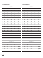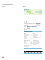
1
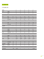
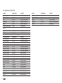
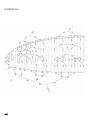
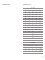
USER’S
MANUAL
ARTIK 4
ARTIK 4
Grand Touring
NIVIUK Gliders ARTIK 4
WELCOME
This manual offers all the necessary information that will familiarize you
with the main characteristics of your new paraglider. Although this manual
informs you about your glider, it does not offer the instruction requirements
necessary for you to be able to pilot this type of wing. Flying instruction
can only be taught at a paragliding school recognized by the Flying
Federation of your country.
We wish to welcome you to our team and thank you for the confidence
that you have placed in a NIVIUK Glider.
We would like to share with you the commitment, the passion and
emotions of the Niviuk design team, which have resulted in the creation of
the new ARTIK 4. Niviuk are very proud of this new glider, a glider carefully
designed to bring you maximum pleasure whilst allowing you learn and
progress.
Only by understanding the pilots, can you offer them what they really need.
This is the reason why we now can deliver a compact, stable, comfortable,
easy to handle glider blessed with a high degree of passive safety.
Go all the way and without limits! Fly kilometer after kilometer to wherever
your imagination leads you; nothing can stop your determination and will
to fly.
We are confident that you will enjoy flying this wing and that you will soon
understand the meaning of our slogan: “The importance of small details”
This is the user’s manual that we recommend you to read in detail.
The NIVIUK Gliders Team.
Niviuk Gliders & Air Games sl C/ Del Ter 6, nave D 17165 La Cellera de Ter - Girona - Spain
Tel. +34 972 42 28 78 Fax +34 972 42 00 86
[email protected] www.niviuk.com
2
USER’S MANUAL
Nevertheless we remind you that it is important that you carefully read all
the contents of the manual for your new ARTIK 4.
Severe injuries to the pilot can be the consequence of the misuse of this
equipment.
SUMMARY
welcome
2
4.3 USING THE ACCELERATOR
10
user’s manual
2
4.4 FLYING WITHOUT BRAKE LINES
10
1. CHARACTERISTICS
4
4.5 KNOTS IN FLIGHT
10
1.1 WHO IS IT DESIGNED FOR?
4
5. LOSING HEIGHT
11
1.2 CERTIFICATION
4
5.1 EARS
11
1.3 IN-FLIGHT BEHAVIOUR
4
5.2 4B2 TECHNIQUE
11
1.4 ASSEMBLY, MATERIALS
5
5.3 B-LINE STALL
12
1.5 ELEMENTS, COMPONENTS
6
5.4 SPIRAL DIVE
12
2. UNPACKING AND ASSEMBLY
6
5.5 SLOW DESCENT TECHNIQUE
12
2.1 CHOOSE THE RIGHT PLACE
6
6. SPECIAL METHODS
13
2.2 PROCEDURE
6
6.1 TOWING
13
2.3 ASSEMBLY TO THE ENGINE
6
6.2 ACROBATIC FLIGHT
13
2.4 TYPE OF HARNESS
6
7. CARE AND MAINTENANCE
13
2.5 ASSEMBLY OF THE ACCELERATOR
7
7.1 maintenance
13
7.2 STORAGE
13
2.6 INSPECTION AND WING
INFLATION ON THE GROUND
7
7.3 CHECKS AND CONTROLS
13
2.7 ADJUSTING THE BRAKES
7
7.4 REPAIRS
14
3. THE FIRST FLIGHT
7
8. SAFETY AND RESPONSABILITY
14
3.1 CHOOSE THE RIGHT PLACE
7
9. GUARANTEE
14
3.2 preparation
7
10. TECHNICAL DATA
15
3.3 FLIGHT PLAN
7
10.1 TECHNICAL DATA
15
3.4 PRE-FLIGHT CHECK LIST
8
10.2 MATERIALS DESCRIPTION
16
10.3 RISERS plan
17
3.5 WING INFLATION, CONTROL,
AND TAKE-OFF
8
10.4 suspension PLAN
18
3.6 LANDING
8
10.5 DIMENSIONS ARTIK 4 21
19
3.7 FOLDING INSTRUCTIONS
8
10.6 DIMENSIONS ARTIK 4 23
19
4. IN FLIGHT
8
10.7 DIMENSIONS ARTIK 4 25
20
4.1 Flying in TURBULENCE
8
10.8 DIMENSIONS ARTIK 4 27
20
4.2 POSSIBLE CONFIGURATIONS
8
10.9 DIMENSIONS ARTIK 4 29
21
10.10 CERTIFICATION SPECIMEN TEST
22
3
1. CHARACTERISTICS
The ARTIK 4 passed the essential load test of 8g without experiencing
any problems.
1.1 WHO IS IT DESIGNED FOR?
The ARTIK 4 has been designed for cross country pilots wanting to
open the door to the world of cross country and for those pilots seeking
to improve their performance in the Grand Touring Class without
compromising safety.
The Artik 4 is an EN C glider. Please, do not use it if you do not have
enough experience to fly this wing category.
Description of an EN C gliders main characteristics:
Moderate passive safety gliders with dynamic reactions in turbulence
and mishandling. Glider recovery can require pilot intervention.
Description of the skills and experience required for EN C gliders:
To be flown only by pilots familiar with recovery techniques, active
piloting, flying in turbulent conditions and able to handle this kind of
demanding aircraft.
Only the aeronautical authorities of the respective countries can
determine the pilot competence.
1.2 CERTIFICATION
The ARTIK 4 has successfully achieved the European EN/LTF
certification. This test was carried out in the Swiss Air-Turquoise
laboratories in Switzerland.
All the commercially available sizes passed every required test with
excellent results and the ARTIK 4 received EN C / LTF C certification for
all sizes.
4
We recommend paying special attention on the flight test report made
by the certification laboratory, and specially attention to the test pilot
comments (Point 25 on the flight test report).
On the flight test report there is all necessary information to know how
the new paraglider will react on each manoeuvre tested.
It is important to take into account that each size can have a different
reaction on the same manoeuvre. Furthermore, the same size on
maximum load o minimum load can experiment a different behaviour.
Check the certification results and figures on the last pages of this
manual or at www.niviuk.com
1.3 IN-FLIGHT BEHAIVOR
With progressive, predictable and efficient handling the ARTIK 4
effectively reads the air mass, seeking out and coring thermals with
efficiency and ease. The ARTIK 4 remains agile, light and predictable in
all conditions of flight and behaves impeccably during turbulence.
The first thing you will notice under the Artik 4 is the softer inflation
followed by the capacity for the glider to take off serenely.
The profile has also been modified and includes the RAM Air Intake
technology to keep the glider steady in any situation. Additionally, it
transmits clear information to the pilot to let him focus on the pleasure of
flying.
With its superb gliding even when fully accelerated, the Artik 4’s
efficiency could be compared to an EN D glider but yet, with the handling
abilities as an EN C wing.
Piloting it is intuitive in all sense; allowing the pilot to make instant
corrective decisions even in strong thermal conditions.
When pushed out, the speedbar is an efficient implement for a smooth,
stable and yet strong acceleration throughout the whole travel range and
hence producing an excellent sink rate as a result. The glider turns more
precisely and effortlessly. Having it all under control you can then, make
better decisions to truly enjoy the flight.
1.4 ASSEMBLY, MATERIALS
The ARTIK 4 has all the technological innovations as used on other
Niviuk gliders. Furthermore it is full of small details destined to enhance
the pilots’ comfort and to improve the performance of the SLE, RAM,
DRS and 3 liner.
SLE.- The SLE allows reinforcement of the leading edge preventing any
deformation during turbulence. The airflow is also vastly improved over
the entire front span of the glider.
RAM.- The RAM air intake allows for optimal air intakes positioning
(below the glider’s leading edge aligned with the intrados), turbulent air
buffering at the front of the wing, bringing more consistency in variable
speeds, and increasing performance while assuring maximum safety.
DRS.-The trailing edge has been reinforced with small ribs that make
thispart flatter in order to spread the pressure out evenly. It means
better air-flow and less drag on this important part of the glider. The
addition of theseribs gives exceptional handling (better and more efficient
whenturning) and more control and precision.
3LT.- Its powerful profile, a detailed internal architecture structure and the
useof high-tech strength materials make possible a significant reduction
of thetotal length of suspension lines in order to reduce the parasite
resistance andthe weight of the glider to gain efficiency.
A whooping 8,77% in weight reduction demonstrates the effort and
accomplishment made to reduce the glider inner bulk and profile
resulting, more performance, enhanced safety and comfort.
The Artik 4 lines are made of Dyneema Liros for the upper cascades
and Vectram Cousin for main and middle cascades. This is the same
material combination found in top gliders.
Both Dyneema and Vectram are unsheathed lines, which are slightly
more exposed to normal wear and tear. It is strongly recommended for
all the lines to be thoroughly inspected every 100 hours of flight. Keep
in mind that we are using materials with great performance of a rigorous
check before each flight.
Not a single millimetre of error is possible in the manufacturing process
from Olivier’s computer to the cutting of the fabric. An automatic process
controlled by a laser-cutting program cuts each of the sections that
compose the different parts of the wing. This program not only cuts the
pieces of fabric but it also paints the guideline marks that will aid the
assembly; it also numbers the separate pieces of material. All this is
carried out before human handling of the pieces begins. So we eliminate
possible and understandable errors that may occur during this delicate
procedure.
The lines are semi-automatically manufactured and all the sewing is
finished under the supervision of our specialists. The jigsaw puzzle of the
assembly process is made easier using this method. We minimize the
processes while making the quality control more efficient. All the different
parts of the canopy are cut and assembled under the strict conditions
induced by the automation of the whole process.
It is strongly recommended that all lines are thoroughly checked by the
pilot prior to every flight and ultimately checked by a service centre or
Niviuk dealer after every 100 hours of flight. We should not forget that we
are using materials with great performance but that they need a rigorous
5
check before every flight.
All NIVIUK Gliders go through an extremely thorough and efficient final
inspection. Every single line of each glider is measured individually once
the final assembly has concluded. Each wing is then individually inflated
for the last visual revision.
Each glider is packaged following the maintenance and conservation
instructions recommended for the advanced materials. NIVIUK Gliders
are made of first class materials as demanded by the performance,
durability, and homologation requirements of the present-day market.
Information about construction materials is given on the last pages of this
manual.
1.5 ELEMENTS, COMPONENTS
The ARTIK 4 is delivered with accessories taking an important role in the
use, transport and storage of the paraglider:
These conditions will allow you to carry out all the steps required for you
to check and inflate the ARTIK 4.
We recommend that an instructor or a retailer supervises the entire
procedure as only they are competent to resolve any doubt in a safe and
professional way.
2.2 PROCEDURE
Take the paraglider out of the rucksack, open it and spread it open with
the lines on top of the underside, position the wing as if you were to
inflate it. Check the condition of the fabric and the lines, making sure
there are no abnormalities.
Check the maillons, which attach the lines to the risers, are properly
closed. Identify and if necessary disentangle the lines from A and B
risers, the brake lines and the corresponding risers. Make sure that there
are no ties or knots.
2.3 ASSEMBLY OF THE HARNESS
- The large capacity Kargo rucksack, ideal for packing the harness as
well as the glider. Capacity and comfort all in one.
- An internal folding bag making the glider folding process easier. An
adjustable folding strap for a quick and easy glider packing.
- One speedbar.
- A small fabric repair kit including auto adhesive rips top with matching
wing color scheme and replacement maillon blockers.
Correctly place the risers on the harness karabiners. The risers and lines
should not have any twists and they should be in the right order. Check
that the harness buckles are correctly locked.
2.4 TYPE OF HARNESS
The Artik 4 can be flown with any kind of harness, including cocoon type
models. The chest strap harness distance for each size:
2. UNPACKING AND ASSEMBLY
Sizes 23 and 25 (42cm) / Sizes 27 and 29 (46 cm).
2.1 CHOOSE THE RIGHT PLACE
We recommend that you unpack and assemble your wing on a schooling
slope or a flat clear area without too much wind and free of obstacles.
6
Incorrect adjustment can seriously affect the piloting of the glider. A
distance, which is too wide between the karabiners, may provide more
feedback but could affect the overall stability of the glider. A distance,
which is too narrow between the karabiners, would provide less feedback
but also increase any risk of developing a twist in during a large collapse.
2.5 ASSEMBLY OF THE ACCELERATOR
The acceleration mechanism of the ARTIK 4 works when you push with
your feet on the accelerator bar, this is supplied with the equipment.
On delivery the accelerator bar has not yet been installed and it is
recommended that it is fit by yourself before flight.
Most harnesses are equipped with a pre-installed acceleration system.
When fitting any accelerator system ensure that all preinstalled items
within the harness, such as roller pulleys are used correctly. After fitting,
take into account that you will have to adjust the length of the accelerator
lines for correct use. This will vary according to the length of the pilot’s
legs!
We recommend that you try the correct fitting of the acceleration system
on equipment designed to do this, most paragliding schools have this
sort of equipment.
The length of the main brake lines is adjusted at the factory to the length
established during certification. However, the length can be changed to
adapt to the pilot’s flying style. Nevertheless, we recommend that you
fly for a while with these, set at the original length. This will allow you to
become accustomed to the ARTIK 4 and its unique flying behaviour. If
you then decide to change the length of the brake lines, untie the knot,
slide the line through the brake link to the desired length, and strongly
re-tie the knot. Qualified personnel should carry out this adjustment. You
must ensure that this adjustment does not slow down the glider without
any pilot input. Both brake lines should be symmetrical and measure the
same length. The most recommended knots are the clove hitch knot or
bowline knot.
When changing the brakes length, it is necessary to check that they do
not act when the accelerator is used. When we accelerate the glider
rotates over the C riser and the trailing edge elevates. We must check
that the brake is adjusted taking in consideration this extra length in
acceleration.
3. THE FIRST FLIGHT
2.6 INSPECTION AND WING INFLATION ON THE GROUND
3.1 CHOOSE THE RIGHT PLACE
Once you have checked all the equipment and made sure that the
wind conditions are favourable, inflate your ARTIK 4 as many times as
necessary in order to become acquainted with the wing’s behaviour.
The ARTIK 4 inflates easily and smoothly. An excess of energy is not
necessary and the wing will inflate with minimum pressure on the harness
when you move forward. This may be assisted by using the A lines. Do
not pull on them; just accompany the natural rising movement of the
wing. Once the wing is in the 12 o’clock position, simply apply correct
pressure on the brake lines and the ARTIK 4 will sit over your head.
We recommend that the first flight with your ARTIK 4 is made on a
smooth slope (a school slope) or in your usual flying area.
3.2 PREPARATION
Repeat the procedures detailed in chapter 2 UNPACKING AND
ASSEMBLY in order to prepare your equipment.
3.3 FLIGHT PLAN
2.7 ADJUSTING THE BRAKES
Draw out a flight plan before take-off in order to avoid possible flight
7
errors.
wrap the brake lines around your hand to get greater braking efficiency.
3.4 PRE-FLIGHT CHECK LIST
3.7 FOLDING INSTRUCTIONS
Once you are ready, but before you take-off, carry out another equipment
inspection. Ensure correct installation of all equipment and that all lines are
free of hindrances or knots. Check that the weather conditions are suited
for your flying skills.
The ARTIK 4 has a complex leading and trailing edge, manufactured using
a variety of different materials. For that reason, the use of a correct folding
method is very important for extending the useful life of your paraglider. It
should be folded like an accordion, with the leading edge reinforcements
flat and the nylon sticks positioned one upon the other. This method will
ensure that the profile remains in good shape without altering its form or
its performance.
3.5 WING INFLATION, CONTROL, AND TAKE-OFF
Smoothly and progressively inflate the wing (chapter 2.6 INSPECTION
AND WING INFLATION ON THE GROUND). The ARTIK 4 inflates easily
and does not require excessive energy. It does not tend to over-take you,
so the wing inflation phase is carried out without anguish. These take off
characteristics provide a perfect control phase and enough time for the
pilot to decide whether to accelerate and take off.
The wing should then be folded in three parts taking care of not bending
or twisting the STE. The wing does not have to be tightly folded, if you do
so it may damage the material and or the lines.
4. IN FLIGHT
Whenever the wind speed allows it, we recommend a reverse launch
technique; this type of launch allows you to carry out a better visual
check of the wing. The ARTIK 4 is especially easy to control in this
position in strong winds. However, wind speeds up to 25 to 30 km/h
are considered strong and extra consideration should be given to any
thought of flight.
Preparation and positioning of the wing on the take-off is especially
important. Choose a location which is appropriate for the direction of the
wind. Position the paraglider as if it were part of a large circle, taking into
account the shape of the canopy in flight. All this will assist in a trouble
free take-off.
3.6 LANDING
The ARTIK 4 lands excellently, it transforms the wing speed into lift on the
pilot’s demand, allowing an enormous margin of error. You will not have to
8
4.1 FLYING IN TURBULENCE
The ARTIK 4 has an excellent profile to withstand the very different aerological conditions so allowing the best possible piloting and stability. It
reacts admirably in passive flight, thus offering a high level of safety in
turbulent conditions. Nonetheless, the pilot always has to pilot according
to the prevailing weather conditions, the pilot is the ultimate safety factor.
We recommend active piloting, making the necessary fine adjustments to
keep the wing in control. He/she should stop braking to allow it to fly at
the required wing speed after a correction is made.
Do not maintain any correction for longer than necessary (braked) this
would cause the wing to enter into critical flying situation. Whenever
necessary, control a situation, react to it and then re-establish the
required speed.
4.2 POSSIBLE CONFIGURATIONS
We recommend that training to master these manoeuvres be carried out
under the supervision of a competent school.
Asymmetric collapse
In spite of the stability of the profile of the ARTIK 4, heavy turbulent
conditions may cause part of the wing to collapse asymmetrically. This
usually happens when the pilot has not foreseen this possible reaction of
the wing. When the wing is about to experience an asymmetric collapse
the brake lines and the harness will transmit a loss of pressure to the pilot.
To prevent the collapse from happening, pull the brake line corresponding
to the compromised side of the wing, this will increase the angle of
incidence. If the collapse does happen the ARTIK 4 will not react violently,
the turn tendency is very gradual and it is easily controlled. Lean your
body towards the side that is still flying in order to counteract the turn and
to maintain a straight course, if necessary slightly slow down the same
side. The collapse will normally open by itself but if that does not happen,
pull completely on the brake line on the side, which has collapsed (100%).
Do this with a firm movement. You may have to repeat this operation to
provoke the re-opening. Take care not to over-brake on the side that is
still flying (turn control) and when the collapse has been solved; remember
to let the wing recover its flying speed.
Symmetric collapse
In normal flying conditions the design of the ARTIK 4 ensures that a
symmetric collapse is quite improbable. The profile of the wing has been
designed to widely tolerate extreme changes in the angle of incidence. A
symmetric collapse may occur in heavy turbulent conditions, on entry or
exit of strong thermals or lack of adapting the use of the accelerator to the
prevailing air conditions. Symmetrical collapses usually re-inflate without
the glider turning but you can symmetrically apply the brake lines with
a quick deep pump to quicken the re-inflation. Release the brake lines
immediately to recover optimum flight speed.
Negative spin
This configuration is out of the normal flight behaviour of the ARTIK 4.
Certain circumstances however, may provoke this configuration such
as trying to turn when the wing is flying at very low speed (while heavily
braking). It is not easy to give any recommendations about this situation
since it varies depending on the circumstances. Remember that you
should restore the relative air speed over the wing. To achieve this,
progressively reduce the pressure on the brake lines and let the wing gain
speed. The normal reaction would be a lateral surge with a turn tendency
no greater than 360º before restoring to normal flight conditions.
Parachutal stall
If it does happen, the feeling would be that the wing would not be
advancing; you would feel a kind of instability and a lack of pressure
on the brake lines, although the canopy would appear to be correctly
inflated. The correct reaction would be to release the pressure on the
brake lines and push the A lines forward or rather lean your body to any
side WITHOUT PULLING ON THE BRAKE LINES.
Deep stall
The possibility of the ARTIK 4 falling into this configuration during normal
flight is very unlikely. This could happen if you are flying at a very low
speed, whilst over steering in a number of manoeuvres and in turbulent
conditions. To provoke a deep stall you have to take the wing to minimum
flight speed by symmetrically pulling the brake lines, when you reach this
point, continue pulling until you reach 100% and then hold. The glider
will first fall behind you and then situate itself above you, rocking slightly,
depending on how the manoeuvre was carried out. When you start to
provoke a stall, be positive and do not doubt an instant. Do not release
the brake lines when half way through the manoeuvre. This would cause
the glider to surge violently forward with great energy and may result
in the wing below the pilot. It is very important that the pressure on the
brake lines is maintained until the wing is well established vertical above.
To regain normal flight conditions, progressively and symmetrically
release the brake lines, letting the speed be re-established. When the
9
wing reaches the maximum advanced position ensure that the brakes
are fully released. The wing will now surge forward, this is necessary so
that air speed is completely restored over the wing. Do not over brake
at this point because the wing needs to recover speed to quit the stall
configuration. If you have to control a possible symmetrical front stall,
briefly and symmetrically pull on the brake lines and let go even when the
wing is still ahead of you.
Wing tangle
A wing tangle may happen after an asymmetric collapse, the end of the
wing is trapped between the lines (Cravat). This situation could rapidly
cause the wing to turn, although it depends on the nature of the tangle.
The correction manoeuvres are the same as those applied in the case
of an asymmetrical collapse, control the turn tendency by applying the
opposite brake and lean your body against the turn. Then locate the line
that reaches the stabiliser that is trapped between the other lines. This line
has a different colour and belongs to the external lines of the C riser.
Pull on this line until it is tense, this should help to undo the wing tangle.
If you cannot undo the tangle, fly to the nearest possible landing spot,
control the flying course with your body movements and a little pressure
on the opposite brake. Be careful when attempting to undo a tangle if you
are flying near a mountainside or near to other paragliders, you may lose
control of the flying course and a collision may occur.
Over handling
Most flying incidents are caused by incorrect actions of the pilot, which
chained one after another creates abnormal flying configurations (a
cascade of incidents). You must remember that over handling the wing will
lead to critical levels of functioning. The ARTIK 4 is designed always to try
to recover normal flight by itself, do not try to over handle it.
Generally speaking, the reactions of the wing, which follow over handling,
are neither due to the input made or the intensity, but the length of time
10
the pilot continues to over handle. You have to allow the profile to reestablish normal flight speed after any type of handling.
4.3 USING THE ACCELERATOR
The profile of the ARTIK 4 has been designed to fly stable through
its entire speed range. It is useful to accelerate when flying in strong
winds or in extreme descending air. When you accelerate the wing, the
profile becomes more sensitive to possible turbulence and closer to a
possible frontal collapse. If you feel a pressure loss, you should release
the pressure on the accelerator and pull slightly on the brake lines to
increase the angle of incidence. Remember that you have to re-establish
the flight speed after correcting the incidence.
It is NOT recommended to accelerate near to the mountainside or in very
turbulent conditions. If necessary you will have to constantly adjust the
movements and pressure on the accelerator whilst constantly adjusting
the pressure applied to the brake lines. This balance is considered to be
“active piloting.”
4.4 FLYING WITHOUT BRAKE LINES
If, for any reason at all, you cannot use the brake lines of your ARTIK 4
you will have to pilot the wing using the C-risers and your body weight
to fly towards the nearest landing. The C-lines steer easily because
they are not under pressure, however you have to be careful not to over
handle them causing a stall or negative turn. To land you have to let the
wing fly at full speed and before reaching the ground you will have to
pull symmetrically on both the C-risers. This braking method is not as
effective as using the brake lines so you will land at a higher speed.
4.5 KNOTS IN FLIGHT
The best way to avoid these knots and tangles is to inspect the lines
before you inflate the wing for take-off. If you notice a knot before take-
off, immediately stop running and do not take-off.
If you have taken-off with a knot you will have to correct the drift by
leaning on the opposite side of the knot and apply the brake line on that
side too. You can gently try to pull on the brake line to see if the knot
becomes unfastened or try to identify the line with the knot in it. Try to
pull the identified line to see if the knot undoes. Be very careful when
trying to remove a knot. When there are knots in the lines or when they
are tangled, do not pull too hard on the brake lines because there is an
increased risk of the wing to stalling or negative turn being initiated
Before trying to remove a knot, make sure there are no pilots flying
nearby and never try these manoeuvres near the mountainside. If the
knot is too tight and you cannot remove it, carefully and safely fly to the
nearest landing place.
5. LOSING HEIGHT
The knowledge of the different descent techniques is an important
resource to use in certain situations. The most adequate descent method
will depend on the particular situation.
go of the lines and the big ears will re-inflate automatically. If they do not
re-inflate, gently pull on one of the brake lines and then on the opposite
one. We recommend that you re-inflate asymmetrically, not to alter the
angle of incidence, more so if you are flying near the ground or flying in
turbulence.
5.2 4B2 TECHNIQUE
On the new generation paragliders the application of big ears can create
a high degree of trailing turbulence which in turn creates a significant
loss of airspeed. When big ears are applied to high aspect ratio wings
the ears tend to “flap” which also adds to the amount of unwanted
turbulence.
This new rapid descent technique was first discovered by our Niviuk
team Pilots in 2009 while flying a competition prototype wing, which
because of its line plan and high aspect ratio would not allow big ears
to be applied. In fact big ears on wings with a profile of 2 lines can often
prove difficult.
We recommend that you learn to use these manoeuvres under the tuition
of a competent school.
For all these reasons, we advise the use of the 4A2 line descent
technique. This technique ensures a rapid descent is achieved whilst
forward wing speed is maintained and so the risk of a deep stall is
eliminated.
5.1 EARS
HOW?
Big ears is a moderate descent technique, achieving about –3 or –4 m/s
and a reduction in ground speed of between 3 and 5 km/h. Effective
piloting then becomes limited. The angle of incidence and the surface
wing load also increases. Push on the accelerator to restore the wing’s
horizontal speed and the angle of incidence.
Locate the 4B2 on your risers and as you would when applying big ears
simply pull down firmly and smoothly until you see both wingtips drop
back slightly. The forward speed of the glider speed will then reduce
slightly, quickly stabilize and then increase. You will then experience
a fall rate of around 5-6m/s. Controlled turning of the wing can easily
be maintained by weight shifting the harness, exactly the same as you
would with big ears. We recommend the application of the speed bar
whilst using this technique. To exit the maneuver release the lines as you
To activate big ears outer line 4A2 on each A risers and simultaneously,
smoothly pull them outward and downward. The wingtips will fold in. Let
11
would with big ears, control the pitch and the wing will quickly adopt
normal flight.
This new technique allows a comfortable and controllable rapid descent
without the risk of experiencing a “cravat” or “deep stall”.
We advise you to first try this technique in smooth conditions with
sufficient altitude above appropriate terrain.
5.3 B-LINE STALL
When you carry out this manoeuvre, the wing stops flying, it loses all
horizontal speed and you are not in control of the paraglider. The air
circulation over the profile is interrupted and the wing enters into a
situation similar to parachuting.
To carry out this manoeuvre you have to take the B-risers below the
maillons and symmetrically pull both of them down (approx. 20-30 cms)
and then hold this position. The initial phase is quite physical (hard
resistance) which means that you will have to pull strongly until the profile
of the wing is deformed, when this happens the required force will then
significantly reduce. To maintain this manoeuvre you must continue to
hold the B Lines in the pulled down position. The wing will then become
deformed, horizontal speed drops to 0 km/h and vertical speed increases
to –6 to –8 m/s depending on the conditions and how the manoeuvre has
been performed.
To exit the manoeuvre, simultaneously release both risers, the wing will
then slightly surge forward and then automatically return to normal flight.
It is better to let go of the lines quickly rather than slowly. This is an easy
manoeuvre but you must remember that the wing stops flying, it loses
all horizontal movement and its reactions are very different compared to
normal flight.This manoeuvre is not possible with this wing.
5.4 SPIRAL DIVE
12
This is a more effective way for rapidly losing height. You have to
know that, the wing can gain a lot of vertical speed and rotation speed
(G force). This can cause a loss of orientation and consciousness
(blackouts). These are the reasons why it is best to carry out this
manoeuvre gradually so your capacity to resist the G forces increases
and you will learn to fully appreciate and understand the manoeuvre.
Always practice this manoeuvre when flying at high altitude.
To start the manoeuvre, first lean your bodyweight and pull the brake line
to the side to which you are leaning. You can regulate the intensity of the
turn by applying a little outside brake.
A paraglider flying at its maximum turn speed can reach –20 m/s,
equivalent 70 km/h vertical speed and stabilize in a spiral dive from 15
m/s onwards.
These are the reasons why you should be familiar with the manoeuvre
and know how to carry out the exit methods.
To exit this manoeuvre you must progressively release the inside brake
and also momentarily apply outside brake. Whilst doing this you must
also lean your bodyweight towards the outside. This exit manoeuvre has
to be carried out gradually and with smooth movements so you can feel
the pressure and speed changes at the same time.
The after effect of the exit manoeuvre is that the glider will rock briefly
with lateral surge, depending on how the manoeuvre has been carried
out.
Practice these movements at sufficient altitude and with moderation.
5.5 SLOW DESCENT TECHNIQUE
Using this technique (do not hurry to descend) we will fly normally,
without forcing neither the material nor the pilot. It means looking for
descending air areas and turn as it was a thermal – in order to descend.
We have to avoid danger areas when looking for descent zones. Safety is
the most important thing.
6. SPECIAL METHODS
6.1 TOWING
The ARTIK 4 does not experience any problem whilst being towed. Only
qualified personnel should handle the qualified equipment to carry out
this operation. The wing has to be inflated in the same way as in normal
flight.
6.2 ACROBATIC FLIGHT
Although the ARTIK 4 has been tested by expert acrobatic pilots in
extreme situations, it HAS NOT been designed for acrobatic flight and we
DO NOT RECOMMEND THE USE OF THIS GLIDER for that use.
become dirty, clean them with a soft damp cloth.
If your wing gets wet with salty water, immerse it in fresh water and dry it
away from direct sunlight. The sunlight may damage the materials of your
wing and cause premature aging. Once you have landed, do not leave
the wing in the sun, store it properly.
If you use your wing in a sandy area, try to avoid the sand from entering
through the cell openings of the leading edge. If sand is inside the wing,
remove it before folding.
If it gets wet of sea water, you should submerge it into fresh water and let
it dry far away from the sun.
7.2 STORAGE
We consider acrobatic flight to be any form of piloting that is different
to normal flight. To learn safely how to master acrobatic manoeuvres
you should attend lessons, which are carried out and supervised by a
qualified instructor over water. Extreme manoeuvres take you and your
wing to centrifugal forces that can reach 4 to 5g.
Materials will wear more quickly than in normal flight. If you do practice
extreme manoeuvres we recommend that you submit your wing to a line
revision every six months.
7. CARE AND MAINTENANCE
7.1 MAINTENANCE
Careful maintenance of your equipment will ensure continued
performance. Always check all the flying equipment before every flight.
Careful maintenance of your equipment will ensure continued
performance. The fabric and the lines do not need to be washed, if they
It is important that the wing is correctly folded when stored. Store your
flying equipment in a cool, dry place away from solvents, fuels or oils. It
is not advisable to store your flying equipment in the trunk of your car.
Temperatures inside a car parked in the sunlight, can be very high. Inside
a rucksack and in the sunlight temperatures can reach 60ºC. Weight
should not be laid on top of the equipment.
If the flying gear is stored with organic material (such as leaves or insects)
inside, the chemical reaction can cause irreparable damage.
7.3 CHECKS AND CONTROLS
You should ensure your ARTIK 4 is periodically serviced and checked
at your local repair shop every 100 hours of use or every 24 months
(whichever happens first). This is the only way to guarantee that your
ARTIK 4 will continue to function properly and therefore continue fulfilling
the homologation certificate results.
In spite of providing much more benefits to the pilots, gliders equipped
13
with unsheathed lines need more care and control of the calibration. The
ARTIK 4 mechanic and UV resistance are one of the highest for this type
of line. With this gliders every little variation on the calibration of the lines
has a directly effect on the performance of the wing.
We recommend checking the lines calibration after the first 30 hours
+/- of flight. This line check is a separate procedure from the regular
inspection after each subsequent 100 hours of use or every two years
(whichever happens first).
Why is it necessary?
Due to the experience acquired over time, constant controls and
inspections conducted by our R&D department in regard to the Abac
Team gliders, we are now able to predict gear aging and how to
appropriately take care of this kind of lines, thus keeping the wing profile
in top performing condition. Following the recommended glider service
checks will keep the wing in optimal performance.
Variable weather conditions in various parts of the world, temperature,
humidity, wing load, will determine and affect to various degrees the
lifespan of the wing and reasons why regular line checks should be
maintained. Inspection must be conducted by certified qualified personal
only. Do not modify you glider in anyway or any reason. Contact your
authorized dealer or Niviuk if in doubt on how to proceed in case of
needed repairs.
7.4 REPAIRS
If the wing is damaged, you can temporarily repair it by using the rip stop
found in the repair kit, so long as no stitches are involved in the tear. Any
other type of tear must be repaired in a specialized repair shop or by
qualified personnel. Do not accept a home repair.
14
8. SAFETY AND RESPONSIBILITY
It is well known that paragliding is considered a high-risk sport, where
safety depends on the person who is practising it.
Wrong use of this equipment may cause severe injuries to the pilot, even
death. Manufacturers and dealers are not responsible for any act or
accident that may be the result of practicing this sport.
You must not use this equipment if you are not trained. Do not take
advice or accept any informal training from anyone who is not properly
qualified as a flight instructor.
9. GUARANTEE
The entire equipment and components are covered by a 2-year
guarantee against any manufacture fault.
The guarantee does not cover misuse or abnormal use of the materials.
10. TECHNICAL DATA
10.1 TECHNICAL DATA
ARTIK 4
CELLS
FLAT
21
23
25
27
29
NUMBER
63
63
63
63
63
CLOSED
10
10
10
10
10
BOX
23
23
23
23
23
AREA
M2
21
23
24,5
26,5
29
SPAM
M
11,32
11,85
12,23
12,71
13,3
6,1
6,1
6,1
6,1
6,1
17,8
19,5
20,77
22,46
24,59
SPAM
9,01
9,43
9,73
10,12
10,59
ASPECT RATIO
4,6
4,6
4,6
4,6
4,6
15
15
15
15
15
MAXIMUM
2,28
2,4
2,47
2,56
2,68
MINIMUM
0,53
0,55
0,57
0,59
0,62
AVERAGE
1,85
1,94
2
2,08
2,18
226
237
245
255
267
HEIGHT
6,9
7,22
7,46
7,75
8,11
NUMBER
226
226
226
226
226
MAIN
1/1/2/3
1/1/2/3
1/1/2/3
1/1/2/3
1/1/2/3
A/a'/B/C
A/a'/B/C
A/a'/B/C
A/a'/B/C
A/a'/B/C
NO
NO
NO
NO
NO
ASPECT RATIO
PROJECTED
AREA
FLATTENING
CORD
LINES
RISERS
M2
%
TOTAL METERS
NUMBER
M
3
TRIMS
ACCELERATOR
m/m
150
150
150
150
150
TOTAL WEIGHT
MINIMUM
KG
50
60
75
90
105
IN FLIGHT
MAXIMUM
KG
70
80
95
110
126
GLIDER WEIGHT
KG
4,3
4,9
5,2
5,6
6
CERTIFICATION
EN/LTF
in process
C
C
C
in process
15
10.2 materials DESCRIPTION
16
CANOPY
FABRIC CODE
SUPPLIER
RISERS
FABRIC CODE
SUPPLIER
UPPER SURFACE
9017 E25
PORCHER IND (FRANCE)
MATERIAL
3455
COUSIN (FRANCE)
BOTTOM SURFACE
D20DMF-36
DOMINICO TEX CO (KOREA)
COLOR INDICATOR
PAD
TECNI SANGLES (FRANCE)
RIBS
9017 E29
PORCHER IND (FRANCE)
THREAD
V138
COATS (ENGLAND)
DIAGONALS
9017 E29
PORCHER IND (FRANCE)
MAILLONS
AS-3.8-20
ANSUNG PRECISION (KOREA)
LOOPS
LKI - 10
KOLON IND. (KOREA)
PULLEYS
224
HARKEN (USA)
REINFORCEMENT LOOPS
W-420
D-P (GERMANY)
TRAILING EDGE REIFORCEMENT
MYLAR
D-P (GERMANY)
REINFORCEMENT RIBS
NYLON STICK
R.P.CHINA
THREAD
SERAFIL 60
AMAN (GERMANY)
SUSPENSION LINES
FABRIC CODE
SUPPLIER
UPPER CASCADES
DC - 40
LIROS GMHB (GERMANY)
UPPER CASCADES
DC - 60
LIROS GMHB (GERMANY)
UPPER CASCADES
DC - 100
LIROS GMHB (GERMANY)
UPPER CASCADES
12100-50
COUSIN (FRANCE)
MIDDLE CASCADES
DC - 40
LIROS GMHB (GERMANY)
MIDDLE CASCADES
DC - 60
LIROS GMHB (GERMANY)
MIDDLE CASCADES
DC - 100
LIROS GMHB (GERMANY)
MIDDLE CASCADES
12240-115
COUSIN (FRANCE)
MIDDLE CASCADES
12470-200
COUSIN (FRANCE)
MIDDLE CASCADES
16140-70
COUSIN (FRANCE)
MIDDLE CASCADES
16330-145
COUSIN (FRANCE)
MIDDLE CASCADES
12100-50
COUSIN (FRANCE)
MIDDLE CASCADES
12240-115
COUSIN (FRANCE)
MAIN
16560-240
COUSIN (FRANCE)
MAIN
12470-200
COUSIN (FRANCE)
MAIN
16140-70
COUSIN (FRANCE)
MAIN
12950-405
COUSIN (FRANCE)
MAIN BREAK
TNL-280
TEIJIM LIMITED (JAPAN)
THREAD
SERAFIL 60
AMAN (GERMANY)
10.3 risers plAN
SIZE 23-25
SIZE 27
17
10.4 SUSPENSION PLAN
18
10.5 DIMENSIONS ARTIK 4 21
10.6 DIMENSIONS ARTIK 4 23
LINES HEIGHT m/m
1
A
B
C
D
br
6786
6693
6882
6973
7482
2
6645
6554
6780
6879
7195
3
6608
6520
6650
6760
6976
4
6605
6521
6629
6737
6977
5
6548
6466
6587
6690
6870
6
6390
6320
6573
6678
6735
7
6345
6282
6622
6720
6663
8
6275
6220
6670
6759
6706
9
6252
6201
6548
6639
6655
10
6267
6236
6472
6565
6624
6456
6645
11
5950
5913
6373
12
5813
5805
6360
13
6318
14
6340
15
6425
16
5858
6757
RISERS LENGHT m/m
A
A’
B
C
470
470
470
470
Standard
312
332
352
470
Accelerated
158
138
118
0
TRAVEL
19
10.7 DIMENSIONS ARTIK 4 25
10.8 DIMENSIONS ARTIK 4 27
LINES HEIGHT m/m
1
LINES HEIGHT m/m
A
B
C
D
br
7020
6923
7119
7219
7739
1
A
B
C
D
br
7330
7230
7433
7539
8089
2
6875
6781
7013
7122
7443
2
7181
7083
7323
7438
7781
3
6838
6747
6880
7000
7217
3
7144
7049
7186
7312
7547
4
6836
6749
6858
6977
7218
4
7143
7053
7163
7288
7549
5
6778
6694
6816
6928
7110
5
7084
7002
7120
7234
7437
6
6616
6543
6802
6916
6970
6
6916
6846
7106
7221
7293
7
6570
6505
6853
6960
6896
7
6868
6801
7160
7267
7216
8
6497
6441
6903
7001
6941
8
6793
6735
7212
7310
7263
9
6474
6421
6779
6868
6889
9
6769
6715
7086
7180
7210
10
6489
6458
6700
6791
6857
10
6786
6753
7004
7100
7178
6680
6880
11
6444
6404
6898
6984
7201
6981
12
6296
6288
6883
11
6161
6123
6599
12
6020
6012
6584
13
6541
13
6838
14
6563
14
6861
15
6652
15
6953
16
6067
16
6340
RISERS LENGHT m/m
A
20
A’
B
7324
RISERS LENGHT m/m
C
A
B
C
470
470
470
470
Standard
470
470
470
Standard
312
332
357
470
Accelerated
312
352
470
Accelerated
158
138
113
0
TRAVEL
158
118
0
TRAVEL
10.9 DIMENSIONS ARTIK 4 29
21
10.10 CERTIFICATION SPECIMEN TEST
ARTIK 4 21
ARTIK 4 23
Class:
C
PG_0892.2014
14. 11. 2014
Niviuk Gliders / Air Games S.L.
Artik 4 23
In accordance with EN standards 926-2:2013 & 926-1:2006:
Date of issue (DMY):
Manufacturer:
Model:
Serial number:
Configuration during flight tests
Paraglider
Accessories
Maximum weight in flight (kg)
80
Range of speed system (cm)
15
Minimum weight in flight (kg)
60
Speed range using brakes (km/h)
15
Glider's weight (kg)
4.9
Range of trimmers (cm)
0
Number of risers
3
Total speed range with accessories (km/h)
31
Projected area (m2)
19.5
Harness used for testing (max weight)
22
Inspections (whichever happens first)
Harness type
ABS
every 24 months or every 100 flying hours
Harness brand
Sup' Air
Warning! Before use refer to user's manual
Harness model
Altiplume
S
Person or company having presented the
glider for testing: None
Harness to risers distance (cm)
44
Distance between risers (cm)
44
1
2
3
4
5
6
7
8
9
10
11
12
13
14
15
16
17
18
19
20
21
22
23
A
A
A
C
A
A
A
A
A
B
A
A
A
C
A
A
A
A
A
A
B
A
0
24
ARTIK 4 25
Class:
ARTIK 4 27
C
Class:
PG_0893.2014
Date of issue (DMY):
14. 11. 2014
Manufacturer: Niviuk Gliders / Air Games S.L.
Model:
Artik 4 25
In accordance with EN standards 926-2:2013 & 926-1:2006:
C
PG_0894.2014
18. 11. 2014
Niviuk Gliders / Air Games S.L.
Artik 4 27
In accordance with EN standards 926-2:2013 & 926-1:2006:
Date of issue (DMY):
Manufacturer:
Model:
Serial number:
Serial number:
Configuration during flight tests
Configuration during flight tests
Paraglider
Accessories
Paraglider
Accessories
Maximum weight in flight (kg)
95
Range of speed system (cm)
15
Maximum weight in flight (kg)
110
Range of speed system (cm)
14
Minimum weight in flight (kg)
75
Speed range using brakes (km/h)
15
Minimum weight in flight (kg)
90
Speed range using brakes (km/h)
15
Glider's weight (kg)
5.2
Range of trimmers (cm)
0
Glider's weight (kg)
5.6
Range of trimmers (cm)
0
Number of risers
3
Total speed range with accessories (km/h)
31
Number of risers
3
Total speed range with accessories (km/h)
31
Projected area (m2)
20.77
Projected area (m2)
22.46
Harness used for testing (max weight)
Inspections (whichever happens first)
Harness used for testing (max weight)
Harness type
ABS
every 24 months or every 100 flying hours
Harness type
ABS
every 24 months or every 100 flying hours
Harness brand
Flugsau
Warning! Before use refer to user's manual
Harness brand
Niviuk
Warning! Before use refer to user's manual
Harness model
Lightsau
Person or company having presented the
glider for testing: None
Harness model
Hamak XL
Person or company having presented the
glider for testing: Olivier Nef
Harness to risers distance (cm)
41
Harness to risers distance (cm)
44
Distance between risers (cm)
44
Distance between risers (cm)
48
1
2
3
4
5
6
7
8
9
10
11
12
13
14
15
16
17
18
19
20
21
22
23
A
A
B
A
A
A
A
A
A
B
A
A
A
C
A
A
A
A
A
B
B
A
0
24
Inspections (whichever happens first)
1
2
3
4
5
6
7
8
9
10
11
12
13
14
15
16
17
18
19
20
21
22
23
B
A
A
A
A
A
A
A
A
B
B
A
A
C
A
A
A
A
A
B
A
A
0
24
23
ARTIK 4 29
24
The importance of small details
niviuk.com