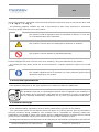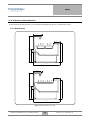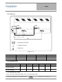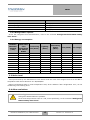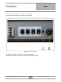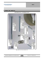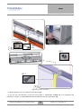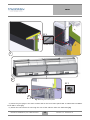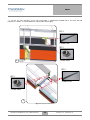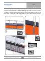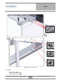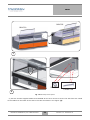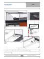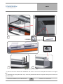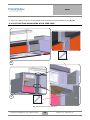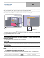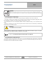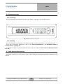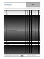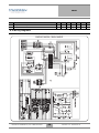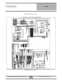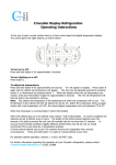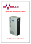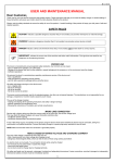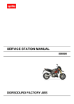
1
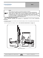
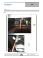
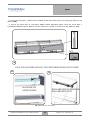
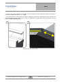
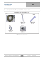
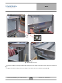
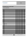
ENIXE
MANUALE DI
INSTALLAZIONE
USO
MANUTENZIONE
ENIXE
1. Introduction ......................................................................................................................................... 5
1.1 Introduction and purpose of the Manual ........................................................................................ 5
1.1.1 Use of this Manual ................................................................................................................... 5
1.2 Warranty conditions ....................................................................................................................... 5
1.3 Graphical conventions .................................................................................................................... 5
1.4 Personnel qualifications ................................................................................................................. 6
1.5 General warnings ........................................................................................................................... 6
1.5.1 To be arranged by the Customer .............................................................................................. 7
1.5.2 Technical assistance ................................................................................................................. 7
1.5.3 Spare parts ................................................................................................................................ 7
2. Information on safety .......................................................................................................................... 8
2.1 General regulations - Training ....................................................................................................... 8
2.2 General regulations - Skills and checks ......................................................................................... 8
2.3 Fire regulations .............................................................................................................................. 8
2.4 First aid regulations ........................................................................................................................ 8
3. Product specification ......................................................................................................................... 10
3.1 General description ...................................................................................................................... 10
3.1.1 Structural components. ........................................................................................................... 10
3.1.2 Functional components .......................................................................................................... 10
3.1.3 Control system ....................................................................................................................... 10
3.2 Technical characteristics .............................................................................................................. 11
3.2.1 Dimensions ............................................................................................................................. 11
3.2.2 Lay-out ................................................................................................................................... 12
3.2.3 Weight table ........................................................................................................................... 12
3.2.4 Admissible loads .................................................................................................................... 12
3.2.5 Refrigeration system: ............................................................................................................. 13
3.2.6 Energy consumption ............................................................................................................... 13
3.3 Noise level .................................................................................................................................... 13
3.4 Other emissions ............................................................................................................................ 13
3.5 Environmental requirements for operation .................................................................................. 14
3.6 Description of residual risks ........................................................................................................ 14
3.7 Specific protections ...................................................................................................................... 15
4. Instructions for commissioning ........................................................................................................ 15
4.1 Transport, handling and positioning ............................................................................................ 15
4.1.1 Precautions to be taken upon receipt of the product .............................................................. 15
4.1.2 Handling and positioning ....................................................................................................... 16
4.2 Unpacking and disposal of packaging materials .......................................................................... 17
4.3 Assembly ...................................................................................................................................... 18
5. ENIXE DUCTING KIT .................................................................................................................... 20
5.1 ASSEMBLY INSTRUCTIONS ’ENIXE’ FLAT SHOULDERS ............................................... 29
5.2 FLAT DUCTING SHOULDERS WITH SIDE CASE ................................................................ 34
5.3 Disassembly and subsequent reassembly ..................................................................................... 35
5.4 Fixing ........................................................................................................................................... 35
5.5 Installation .................................................................................................................................... 35
5.5.1 Connection to a remote condensing unit ................................................................................ 35
Manuale di Installazione, Uso e Manutenzione
3
Versione 1.0 - Revisione 00
ENIXE
5.5.2 Connection to the mains ......................................................................................................... 36
5.5.3 Connection to the drain line ................................................................................................... 36
5.6 Commissioning ............................................................................................................................ 37
5.6.1 Starting: .................................................................................................................................. 37
5.6.2 Setting .................................................................................................................................... 37
5.7 Idle time and restarting ................................................................................................................ 37
6. Instructions for use ............................................................................................................................ 38
6.1 Correct use of the cabinet ............................................................................................................. 38
6.2 Uses to be avoided ....................................................................................................................... 38
6.3 Working limits ............................................................................................................................. 39
6.4 Cabinet control functions ............................................................................................................. 39
6.4.1 Manual defrosting .................................................................................................................. 39
7. Maintenance instructions .................................................................................................................. 39
7.1 General warnings ......................................................................................................................... 39
7.2 Periodical cleaning ....................................................................................................................... 39
7.3 Bulb replacing .............................................................................................................................. 40
7.4 Periodical maintenance ................................................................................................................ 40
7.4.1 Check of the glass lifting system ........................................................................................... 40
7.5 Special maintenance ..................................................................................................................... 40
7.6 Troubleshooting ........................................................................................................................... 41
8. Instructions for demolition and disposal ........................................................................................... 41
9. Parameter table of control panel ....................................................................................................... 42
9.1 List of parameters ......................................................................................................................... 42
9.2 Wiring diagrams ........................................................................................................................... 44
10. Attachments .................................................................................................................................... 46
10.1 Reference to manuals of other suppliers .................................................................................... 46
10.2 Declaration of conformity: as attached ...................................................................................... 46
Manuale di Installazione, Uso e Manutenzione
4
Versione 1.0 - Revisione 00
EPS
1. Introduction
1.1 Introduction and purpose of the Manual
Thank you for choosing Criocabin S.p.a., hereinafter referred to as the Manufacturer. We are glad to
have you as our Customer and hope you will be fully satisfied with this product.
This Use and Maintenance Manual is an integral part of the product and is aimed at anyone
who works on the product or interacts with its users.
The purpose of this Manual is to supply the necessary information to enable:
• quick identification of the product parts;
• all the commissioning, functioning and maintenance operations to be carried out on the
product;
• the health and safety of all users and exposed persons to be guaranteed at all stages.
All information, drawings, diagrams, tables and any other contents of this Use and Maintenance Manual
are confidential and therefore the full or partial reproduction or disclosure thereof to third parties is
subject to the authorisation of the Manufacturer in its capacity as sole owner.
1.1.1 Use of this Manual
Read this manual before handling, installing and using the product, and likewise before carrying out
any maintenance work on it.
The term Manufacturer will always be used to indicate Criocabin S.p.a., while the generic term Supplier
will be used to indicate other manufacturers of specific components fitted in the product.
The term Dealer will be used to indicate the company that, according to a distribution agreement
signed with the Manufacturer, is authorised to sell the product and constitutes the Customer’s
commercial counterpart.
Keep this manual away from sources of heat, dampness and corrosive agents throughout the product
working life, pass it on to any other user or subsequent owner and keep it handy for easy reference by
its users.
Handle this manual with care; do not damage it, tear out pages or modify its content for any reason.
The Manufacturer reserves the right to communicate at any moment any information which is
considered necessary for a better and safer use of the product. Such information, provided as
modifications, updating or additions, will have to be considered in all respects as an integral part of this
manual.
1.2 Warranty conditions
Warranty conditions are stated in the sales agreement which is accepted by the Customer by means
of order confirmation.
1.3 Graphical conventions
Bold type is used to highlight information considered important.
References to illustrations are made by means of a number in bold type that identifies the illustration
(i.e. Fig. 1) and, if necessary, by means of a letter or number that identifies the component in question
Manuale di Installazione, Uso e Manutenzione
5
Versione 1.0 - Revisione 00
EPS
within the illustration. Illustration references and component references may be used at the same time
(i.e. A - Fig. 1 or 1 - Fig. 1).
The following graphical symbols are used in this Manual to draw users’ attention to information
concerning proper and safe use of the product:
NOTE!
This symbol is used to highlight a piece of information or advice, or a rule which is considered particularly important.
!
CAUTION!
This symbol is used to point out a dangerous operation or situation.
PROHIBITED OPERATION!
This symbol is used to indicate a prohibited operation.
Additionally, the graphical symbols listed below are employed in this manual to show the Personal
Protective Equipment which must be worn when installing, using and maintaining the product.
The symbol for each safety device will be found whenever a specific operation requires use of said
device.
PERSONAL PROTECTIVE EQUIPMENT
This symbol indicates that it is compulsory to wear protective gloves during
operations marked by this symbol.
1.4 Personnel qualifications
Here follows a description of the type of personnel to whom this Manual is addressed.
Qualified
The Qualified Technician is a specialised technician who is supplied by the Customer or
by the Dealer and is authorised, under different circumstances, to carry out operations
such as assembly, disassembly, installation, set-up, start-up, maintenance and repair.
1.5 General warnings
All the indicated safety regulations must be strictly observed by the users of the product.
The instructions written on this Manual will be the object of a training activity given by the Dealer’s
technical personnel during installation. The Customer will be responsible for selecting, inside their
organisation, the people to whom such training activity is addressed and for checking that the trained
personnel have reached a learning level which is apt for the tasks assigned to them.
The diagrams enclosed in this Manual are to be used only for extraordinary maintenance and controls.
Manuale di Installazione, Uso e Manutenzione
6
Versione 1.0 - Revisione 00
EPS
Note!
It is strictly forbidden to use them to carry out modifications on the product.
Possible modifications are to be required directly to the Dealer, specifying all
the product technical features and the reasons for such modifications; if
approved, modifications must be carried out only by the Manufacturer’s
personnel or by authorised personnel.
Note!
Any non-authorised tampering/replacement of one or more parts or units of the
product may cause accidents and exempt the Manufacturer from civil and
criminal liability.
1.5.1 To be arranged by the Customer
Provided for otherwise by special contractual conditions, the Customer is responsible for
arranging the following:
•
•
•
•
selecting the people to whom the training on the product use is addressed;
arranging a suitable place for product installation;
checking that the received product corresponds to the order specifications;
carrying out all the activities described in the present manual, except where expressly indicated
otherwise.
1.5.2 Technical assistance
The Customer may require technical assistance by contacting directly the Dealer’s Customer Service
according to the ways specified in the Sales Agreement.
1.5.3 Spare parts
Note!
The Customer must always use original spare parts supplied by the Manufacturer.
The Manufacturer cannot be held responsible for any damage or injury or any other inconvenience arising from the use of non-original spare parts.
Drawing, references, descriptions and serial numbers for the identification of all the mechanical parts
are listed in the section Spare Parts.
With regard to the electrical and electronic equipment, please refer to the electrical diagrams 1 and 2.
Note!
When ordering new spare parts, always quote the model and serial number of
the product for which the spare parts are required.
Manuale di Installazione, Uso e Manutenzione
7
Versione 1.0 - Revisione 00
EPS
2. Information on safety
2.1 General regulations - Training
• It is recommended that any person who interacts with the product reads this Manual completely
before starting to operate.
• Negligence or failure to comply with these safety regulations while using and maintaining the
product may cause accidents for which the Dealer and the Manufacturer are not responsible.
• Finally, it is hereby reminded that according to the provisions of the law in force:
Note!
Workers must follow the orders and instructions given by the employer.
2.2 General regulations - Skills and checks
• Only qualified and authorised technical personnel can install, set and carry out extraordinary
maintenance on the product.
• The product has been designed only for holding food and shall not be used for any other
purpose.
• Always use the Personal Protective Equipment when recommended.
• Arrange fire-fighting equipment adequate to the product technical features.
2.3 Fire regulations
!
Warning!
When put in contact with free flames, the refrigerant fluid undergoes a thermal decomposition into a caustic and poisonous substance.
Avoid exposition to sparks and sources of inflammation.
2.4 First aid regulations
The following first aid regulations concern the treatment of injuries that could be caused by the
refrigerant fluid.
Manuale di Installazione, Uso e Manutenzione
8
Versione 1.0 - Revisione 00
EPS
Warning!
If a refrigerant fluid comes into contact with eyes:
do not rub the eyes;
remove contact lens;
!
rinse thoroughly for at least 20 minutes.
If a lubricant comes into contact with skin:
wash the skin with a great quantity of water for at least 20 minutes;
leave the skin uncovered.
If a lubricant is swallowed:
drink as much water as possible.
In all the above cases, bring the injured person to the nearest medical facility.
Note!
For further details, refer to the "Safety data sheet" of the refrigerant fluid.
Manuale di Installazione, Uso e Manutenzione
9
Versione 1.0 - Revisione 00
ENIXE
3. Product specification
3.1 General description
3.1.1 Structural components.
The above mentioned cabinet is provided with:
ENIXE 400 / 410
•
•
•
•
•
•
•
•
•
•
•
Multiplexable to all other Enixe versions with flat, mirroed endwalls.
Food tray heating in bain-marie (EI400) or hot surface versions (EI410).
Heating unit on top part.
304 stainless-steel scratchproof work surface.
AISI 304 stainless-steel unit interior.
Electronic panel.
Superstructure with front uprights with upward-opening square glass.
Fixed 36 cm glass top surface.
Personalised front.
Perimetrical bumper skirting.
Supplied with ready-fitted cabinet.
3.1.2 Functional components
The cabinet is available in two versions:
• built-in condensing unit (cabinets with "refrigeration unit");
• with remote condensing unit (cabinets "without refrigeration unit")
All adopted materials are certified for use in food industry and the refrigerants are in conformity with
the Regulations in force.
3.1.3 Control system
It is performed through control units.
For specific instructions on its use, refer to the enclosed "Carel control unit instructions for use" .
Manuale di Installazione, Uso e Manutenzione
10
Versione 1.0 - Revisione 00
ENIXE
3.2 Technical characteristics
In this manual all dimensions in the technical drawings are given in millimeters (mm).
3.2.1 Dimensions
360
586
870
1200
290
1168
360
586
870
1200
290
1168
Fig. 1 Dimensions Enixe 400 410
Manuale di Installazione, Uso e Manutenzione
11
Versione 1.0 - Revisione 00
ENIXE
3.2.2 Lay-out
= QUADRO ELETTRICO
= SCARICO ACQUA
= TUBO GAS
Fig. 2 Lay-out
Lenght
A (mm)
A1 (mm)
B (mm)
B1 (mm)
1250
113
/
625
/
1875
113
/
625
/
2500
113
1.363
625
1.875
3.2.3 Weight table
Cabinet length (mm)
937
1250
1875
2500
3125
3750
Weight (kg) (refrigeration 100
unit not included)
125
185
250
310
370
Weight (kg) (refrigeration 130
unit not included)
160
220
280
340
410
3.2.4 Admissible loads
As for the cabinet admissible loads, refer to the following table:
Manuale di Installazione, Uso e Manutenzione
12
Versione 1.0 - Revisione 00
ENIXE
COMPONENTS
LOAD
Top canopies, alluminium
max kg 20/m
Top canopies, glass
max kg 8/m
Intermediate shelves
max kg 8/m
Display surfaces
max kg 95/m
3.2.5 Refrigeration system:
As for the refrigerant fluid characteristics, refer to the enclosed "Refrigerant fluid R404a safety
data sheet".
3.2.6 Energy consumption
CABINET
SECTION
LENGTH
(mm)
REFRIGERATING CAPACondensing
CITY
REQUIRED unit (Watt)
TO THE CABINET
Lighting
(Watt)
Defrosting
heater
(Watt)
Fans (Watt) Gas charge
937
315
430
18
40
225
700
1250
425
430
30
40
300
700
1875
615
500
58
80
450
750
2500
815
590
66
80
600
1000
3125
1010
950
94
120
750
1250
3750
1200
950
102
120
900
1400
AA45
310
400
30
40
225
/
AA90
460
380
48
80
300
750
AC45
310
430
30
40
225
700
AC90
460
430
48
80
450
750
3.3 Noise level
Tests performed by the Manufacturer have shown that the noise level ranges from 55 to 57 dBA in
compliance with the EU Directive no. 89/392/EEC.
Noise level depends also on room temperature and, as for cabinets "with refrigeration unit", on the
condensing unit cleaning level.
3.4 Other emissions
!
Warning!
Refrigerant R404a leaks are possible.
As for first aid provisions refer to and, more specifically, to the enclosed "Refrigerant
R404a safety data sheet".
Manuale di Installazione, Uso e Manutenzione
13
Versione 1.0 - Revisione 00
ENIXE
3.5 Environmental requirements for operation
To maintain the refrigerating cabinet in good working conditions check that the cabinet temperature
class corresponds to that of the room where the cabinet has been installed (see rating plate).
To maintain in good conditions cabinets provided with a refrigerating unit, act as follows:
• guarantee air exchange in the room, even at floor level, also when the sales outlet is closed;
• do not obstruct the condensing unit air outlets by placing products or materials around the
cabinet.
In case of cabinets "without refrigeration unit", act as follows:
• locate the remote condensing unit in a place sheltered from the atmospheric agents.
In any case, act as follows:
• install the cabinet avoiding exposure to direct sunlight and to any other source of heat such as
high-intensity incandescent lighting, ovens or heat-emitting bodies such as radiators;
• position the cabinet away from doors, windows, air-conditioning outlets to avoid air flows
exceeding 0.2 m/s.
Note!
A room temperature rising and/or a lack of air to the condensing unit not only increases
energy consumption but also reduces the cabinet technical performances and may lead
to the deterioration of displayed products.
The cabinet operating room temperature is 25 °C ± 1 °C. The environment humidity shall be 60% ±
3%.
3.6 Description of residual risks
Warning!
DANGER OF CUTTING
!
When cleaning the cabinet tray, after having removed the display shelves, be careful not
to injure yourself on the evaporator fins as they may be sharp due to their reduced thickness.
When cleaning the condensing unit of cabinets provided "with a refrigerating unit", be
careful not to injure yourself on the condensing unit fins, as they may be sharp due to
their reduced thickness.
PERSONAL PROTECTIVE EQUIPMENT
It is compulsory to wear protective gloves when performing the above mentioned cleaning operations.
!
Warning!
DANGER OF BURNS
In case of cabinets provided with electric defrosting, be careful not to get burnt by the
heater, as this may still be hot.
In case of infrared lamp heated cabinets, be careful no to get burnt by hot parts.
Manuale di Installazione, Uso e Manutenzione
14
Versione 1.0 - Revisione 00
ENIXE
Warning!
DANGER OF CRUSHING
!
Cabinet front glasses open by means of piston system. Pistons act as a lifting back-up
and prevent the glass from accidental and unexpected falling.
To avoid danger of crushing, check periodically the system efficiency and check if the effort required to lift the glass is increasing, as this will indicate a reduced efficiency of the
lifting system.
Warning!
DANGER OF GLASS BREAKING
!
All movable glasses are hardened and, if broken, fragment in pieces not longer than 3cm,
thus reducing the risk of damaging people.
During the normal use of the cabinet glasses are lowered, thus avoiding any danger of
breaking due to glass falling.
To store goods and for cleaning purpose glasses are lifted and kept open thanks to the
lifting system.
3.7 Specific protections
Normally, the refrigeration system components and the control panel are not accessible. They are
sheltered by means of panels placed on the cabinet rear side.
Prohibition!
Except when special maintenance is performed, it is forbidden to remove the panels or
use the cabinets when the panels have been removed or are open.
4. Instructions for commissioning
4.1 Transport, handling and positioning
4.1.1 Precautions to be taken upon receipt of the product
The Manufacturer supplies the cabinet ex-works. Before delivery to the carrier, the material, subject
matter of the supply contract, shall be carefully inspected by the Manufacturer.
The Manufacturer cannot be held responsible for missing parts or damage to parts that might occur
after delivery to the carrier.
Note!
The cabinet components are usually packed; non-packed components have to
be covered during transport.
All loose components that might move during transport must be firmly secured.
Manuale di Installazione, Uso e Manutenzione
15
Versione 1.0 - Revisione 00
ENIXE
Note!
Upon receipt of the cabinet, the Customer shall act as follows:
Check that the supplied material corresponds to the order specifications.
Check that the cabinet has not been damaged during transport, that the
packaging, if any, has not been tampered with and that no part is missing.
In case of damage or missing parts, immediately inform the carrier and the
Manufacturer producing photographic proof.
4.1.2 Handling and positioning
Unless otherwise specified, the Customer is responsible for the above mentioned
operations.
To handle the cabinet use a forklift truck of suitable capacity. Refer to the gripping-lifting areas shown
in the picture below.
As for the weight of the cabinet, refer to “3.2 Technical characteristics” on page 11.
Fig. 3 Handling ENIXE
Manuale di Installazione, Uso e Manutenzione
16
Versione 1.0 - Revisione 00
ENIXE
Note!
It is recommended to move the cabinet only by means of a pallet.
Check the correct balancing of the cabinet before lifting it completely.
Lifting has to be smooth (avoid jerks and jolts).
Make sure that the cabinet has been positioned completely flat. If necessary, adjust the feet screws
and check the position of the cabinet with a spirit level. The cabinet must be placed on a completely flat
surface to ensure correct operation, to drain any condensing water and to avoid noisy vibrations from
the motor.
In case of cabinets provided with a condensate collection tank, make sure that the collection tank has
been positioned so that to allow the connection of the relative drainage pipe to the hydraulic system.
4.2 Unpacking and disposal of packaging materials
Unless otherwise specified, the Customer is responsible for the operations mentioned
below.
Remove the packaging only after having positioned the unit.
Packaging must be disposed of in compliance with the laws in force.
Manuale di Installazione, Uso e Manutenzione
17
Versione 1.0 - Revisione 00
ENIXE
4.3 Assembly
Unless otherwise specified, the Customer is responsible for the operations mentioned
below.
4
5
Fig. 4 Water pipe connection
Manuale di Installazione, Uso e Manutenzione
18
Versione 1.0 - Revisione 00
ENIXE
Single out the water pipe located under the tank (4).
Connect a pipe suitable to the existing coupling (5).
7
6
Fig. 5 Control board setting
Set water temperature by means of the thermostat (6).
Set the heating lamp intensity by means of the intensity dial (7).
Manuale di Installazione, Uso e Manutenzione
19
Versione 1.0 - Revisione 00
ENIXE
5. ENIXE DUCTING KIT
RIFERIMENTI KIT / REFERENCES KIT
Fig. 6 ENIXE DUCTING HARDWARE KIT
Manuale di Installazione, Uso e Manutenzione
20
Versione 1.0 - Revisione 00
ENIXE
SPUGNA ADESIVA
FOAM ADHESIVE
SILICONE
SILICON
1
RIF. 1
C50006050
RIF. 2
C50001880
2
Fig. 7 Ducting the first phase
a) Bring together the two cabinets to be ducted (1)
b) To join the two cabinets, secure the screw REF. 1 C50006050 SCREW M6 X 30 TCEI ZN with
respective nut REF. 2 C50001880 NUT M6 ZN between the two angle bars (2)
Manuale di Installazione, Uso e Manutenzione
21
Versione 1.0 - Revisione 00
ENIXE
RIF 4
C50001970
3
4
RIF 1
RIF 2
C50006050
C50006050
5
Fig. 8 Ducting the second phase
a) Insert the joint plugs in the work surface and on the front frame panel REF. 4 C50001970 CYLINDR.
PLUG ZN D. 4X40 (3)
b) Follow the instructions for securing the rear of the cabinet under the backrests (4)
Manuale di Installazione, Uso e Manutenzione
22
Versione 1.0 - Revisione 00
ENIXE
c) To join the two cabinets, secure the screw REF. 1 C50006050 SCREW M6 X 30 TCEI ZN and
respective nut REF. 2 C50001880 NUT C50001880 M6 ZN (5)
RIF 5
C50001040
RIF 2
C50001880
6
RIF 5
RIF 2
C50001040
C50001880
7
Fig. 9 Ducting the third phase
Manuale di Installazione, Uso e Manutenzione
23
Versione 1.0 - Revisione 00
ENIXE
a) Secure using the screw REF. 5 C50001040 SCREW M 6X 100 TE ZN and respective nut REF. 2
C50001880 NUT AND M 6. under the cabinet work surfaces (6)
b) Repeat the securing procedure described previously at the points marked with a red dot in the
figure. Always use screws. REF. 5 C50001040 SCREW M6 X 100 TE ZN and respective nut REF. 2
C50001880 NUT M6 ZN (7)
8
RIF 1
C50006050
RIF 2
9
C50001880
RIF 6
C50005320
RIF 9
C50003110
Manuale di Installazione, Uso e Manutenzione
24
Versione 1.0 - Revisione 00
ENIXE
Fig. 10 Ducting the fourth phase
a) To join the two cabinets, secure the screw REF. 1 C50006050 SCREW M6 X 30 TCEI ZN and
respective nut REF. 2 C50001880 NUT M6 ZN (8)
b) Secure using the screws REF. 6 C50001040 SCREW M6 X 100 TE ZN and respective nut REF. 9
C50003110 NUT M8 ZN. the bottom of the front of the cabinet (9)
Manuale di Installazione, Uso e Manutenzione
25
Versione 1.0 - Revisione 00
ENIXE
RIMUOVERE VETRO / REMOVE GLASS
RIF 4
C50001970
10
11
RIF 2
C50001880
RIF 8
C70100000
RIF 7
C50005590
Fig. 11 Ducting the fifth phase
a) Remove:
• Cover glass (10)
• Ceiling lamp heads (10)
• Top bracket covers (10)
Manuale di Installazione, Uso e Manutenzione
26
Versione 1.0 - Revisione 00
ENIXE
b) Insert the plugs REF. 4 C50001970 CYLINDR. PLUG ZN D.4X40 on all the ceiling plug holes on one
cabinet (10)
c) Secure the plate REF. 8 C70100000 ENIXE SHELF DUCTING PLATE using the screw REF. 7
C50005590 SCREW M 5X 12 TBEI IX and the respective nut REF. 2 C50003110 NUT AND M 5 (11)
RIF 3
C50001720
12
SOLO CON CHIUSURA IN PLEXI / ONLY WITH REAR PLEXIGLASS CLOSURE
13
14
ALLENTARE VITI
LOOSEN SCREW
REGOLARE PROFILO SUPERIORE
REGULAR PROFILE TOP
Fig. 12 Ducting the sixth phase
Manuale di Installazione, Uso e Manutenzione
27
Versione 1.0 - Revisione 00
ENIXE
a) To fix the sheet upstands in the back of the assembled counters with self-drilling screws REF 3
C50001720 SCREW YOU AP 4.2 X 13 (12)
b) b) If the counter is fitted with rear closure Plexiglass, during the multiplexetion of the counters the
upper and lower profiles must move in order to compensate for gaps that may arise between the two
counters (13) (14) (15) (16)
15
16
Fig. 13 Ducting the seventh phase
Manuale di Installazione, Uso e Manutenzione
28
Versione 1.0 - Revisione 00
ENIXE
5.1 ASSEMBLY INSTRUCTIONS ’ENIXE’ FLAT SHOULDERS
RIFERIMENTI KIT / REFERENCES KIT
RIF 1
RIF 2
C600001080
C50001730
PZ = 12
RIF 5
RIF 3
C50004110
PZ = 3
RIF 6
C50004110
PZ = 12
C50003310
PZ = 1
Fig. 14 References kit flat shoulders
Manuale di Installazione, Uso e Manutenzione
29
Versione 1.0 - Revisione 00
ENIXE
RIF 1
1
C60001080
2
Fig. 15 Assembly first phase
a) Apply the adhesive sponge C60001080 along the entire edge of the tank of the cabinet to be ducted
(1)
b) Apply the silicone along the entire edge of the tank above the adhesive sponge (2)
Manuale di Installazione, Uso e Manutenzione
30
Versione 1.0 - Revisione 00
ENIXE
BANCO B
BANCO A
3
52000053
C50001730
4
Fig. 16 Assembly second phase
a) Use the screws supplied C50001730 SCREW AF 4.8 X 60 TC-IC to secure the side from the inside
of the cabinet to the back of the side in the tank as shown in the figure (4)
Manuale di Installazione, Uso e Manutenzione
31
Versione 1.0 - Revisione 00
ENIXE
5
C50001730
52000053
6
Fig. 17 Assembly third phase
a) Use the screws supplied C50001730 SCREW AF 4.8 X 60 TC-IC to secure the side from the inside
of the cabinet to the back of the side in the tank as shown in the figure (5)
b) At the front of the tank, secure the side using screws C50001730 SCREW AF 4.8 X 60 TC-IC as
shown in the figure (6)
Manuale di Installazione, Uso e Manutenzione
32
Versione 1.0 - Revisione 00
ENIXE
7
52000053
C50001730
C50003310
9
8
Fig. 18 Assembly fourth phase
a) Secure the screw C50001730 SCREW AF 4.8 X 60 TC-IC on the metal plate as shown in the figure
(7)
b) Assemble the two glass sides. they must be positioned inside the supports that protrude from the
top of the sides.
Manuale di Installazione, Uso e Manutenzione
33
Versione 1.0 - Revisione 00
ENIXE
c) Secure the glass using the chromeplated boss C50003310 GLASS HOLDER D.35 (8) (9)
5.2 FLAT DUCTING SHOULDERS WITH SIDE CASE
C50004110
10
11
C50004110
Fig. 19 Assembly first phase side case
Manuale di Installazione, Uso e Manutenzione
34
Versione 1.0 - Revisione 00
ENIXE
a) For ducting with the side case at the front of the cabinet, secure the screw C50004110 SCREW AF
4.8 X 32 TC-IC in the angle bar fixed under the side case frame profile (10)
b) At the bottom, using screws once again C50004110 SCREW AF 4.8 X 32 TC-IC secure the top of the
side case and then the bottom to the side as shown in the figure to the left (11)
12
C50004110
Fig. 20 Assembly second phase side case
a) Complete securing by affixing the screw C50004110 SCREW AF 4.8 X 32 TC-IC to the point shown
in the figure located inside the side case (12)
5.3 Disassembly and subsequent reassembly
The Customer is responsible for the cabinet disassembly in order to move it and for its
subsequent reassembly.
For technical service, the Customer can apply to the Reseller.
5.4 Fixing
The cabinet described in this manual is provided with screw feet and therefore does not need to be
fixed to the floor.
5.5 Installation
Unless otherwise specified, the Customer is responsible for the operations mentioned
below.
5.5.1 Connection to a remote condensing unit
The connection to a remote condensing unit concerns only cabinets "without a refrigeration unit".
Manuale di Installazione, Uso e Manutenzione
35
Versione 1.0 - Revisione 00
ENIXE
Qualified
Both the connection and the start-up shall be carried out by a Refrigerant Specialist.
Refer to the cabinet layout for the position of the refrigerant fluid intake and outlet pipes.
5.5.2 Connection to the mains
Connect the cabinet to a mains power supply having an impedance lower than 0.228 ohm.
Line supply, frequency and voltage must correspond to those stated on the cabinet rating plate. When
the compressor is started, the nominal voltage must be within ± 10%.
We recommend the use of a omnipolar isolation switch of adequate rating (C or D) upstream of the
outlet.
Moreover, according to the law, both the system and the socket must be connected by a differential
switch with 0.03 A release current.
!
Warning!
The cabinet must be earthed.
Before plugging in cabinets "with a refrigeration unit", check that the isolator is open, in 0, OFF or
green position. Then plug the cabinet in and turn on the switch.
Note!
Refer to “9. Parameter table of control panel” on page 42
5.5.3 Connection to the drain line
The cabinet must be connected to a drain line if it is not provided with tanks collecting the condensate
coming from inside the cabinet tank. In this case, connect the condensate drainage pipe to the drain line
of the place where the cabinet has been installed.
Manuale di Installazione, Uso e Manutenzione
36
Versione 1.0 - Revisione 00
ENIXE
5.6 Commissioning
5.6.1 Starting:
Start-up settings are performed through a key panel, as shown in the following figure.
Fig. 21 Carel control unit key panel
5.6.2 Setting
Start-up settings are performed in the factory during the testing procedure by the Manufacturer.
As for set-up operation parameters, refer to the List of parameters in “9. Parameter table of
control panel” on page 42.
To modify the above mentioned parameters, refer to the enclosed "Carel control unit instructions
for use".
5.7 Idle time and restarting
No special measures must be taken in case of prolonged idle times and subsequent restarting of the
cabinet.
Manuale di Installazione, Uso e Manutenzione
37
Versione 1.0 - Revisione 00
ENIXE
6. Instructions for use
the Customer is responsible for the operations mentioned below.
6.1 Correct use of the cabinet
Note!
When using the cabinet we recommend to observe with the utmost
scrupulousness the principles of the Hazard Analysis and Critical Control Point
(Haccp) concerning:
personal hygiene of all the operators of food service;
plant hygiene;
food transport;
interrupted cold chain;
food preservation.
Note!
In particular:
products must be brought from the warehouses at a temperature close to their ideal storage temperature and immediately placed in the cabinet.
Filling the cabinet with products whose temperature is higher than that of the cabinet
itself may make the cabinet operating conditions worse and even deteriorate the conservation of the already displayed goods.
To ensure the cabinet good operating conditions, displayed good must not obstruct the
refrigerated air circulation.
Note!
Front glasses must be lifted to their maximum opening point and kept open only as long
as it takes to store or remove food, or for cleaning purposes. Pistons act as a lifting backup and prevent the glass from accidental falling.
If cabinets are provided with hatches, these must be opened only as long as it takes to
store or remove food in order to avoid an anomalous rising of the cabinet working temperature.
6.2 Uses to be avoided
Prohibition!
Do not set temperatures lower than those recommended for the cabinet category. This
would not bring any advantage and may block the evaporator.
Do not store goods over the maximum load line. This may cause ice formation on the
evaporator, which may damage the thermal conditions of the correctly stored products.
Do not obstruct the air inlet grille located in the display surface front side.
Manuale di Installazione, Uso e Manutenzione
38
Versione 1.0 - Revisione 00
ENIXE
6.3 Working limits
Refer to the enclosed "Carel control unit instructions for use".
6.4 Cabinet control functions
Here are the cabinet control functions reckoned among the Customer’s common skills:
•
•
•
•
•
cabinet switching on;
manual defrosting of the evaporator;
setting temperature;
periodical cleaning and maintenance;
cabinet switching off.
To carry out the listed control functions, refer to the enclosed "Carel control unit instructions for
use".
6.4.1 Manual defrosting
In order to avoid ice formation on the evaporator and consequent reduction of cold air flow, the unit
has an automatic system that will defrost the cabinet periodically, whose daily frequency has been preset
by the Manufacturer during the testing procedure.
In case of an anomalous reduction of the refrigerated air flow, the manual defrosting of the cabinet
must be carried out.
7. Maintenance instructions
7.1 General warnings
Maintenance operations described in this manual concern planned routine maintenance. The
Customer is responsible for the routine maintenance of the equipment.
Special maintenance shall be carried out only by qualified personnel according to what stated in the
"Maintenance Manual", which is not an integral part of this manual.
7.2 Periodical cleaning
!
Warning!
Before starting to clean the cabinet, unplug it from the mains.
Cabinet cleaning:
• Clean every day the areas around the display surface with water and a neutral detergent, then
dry the parts with a soft cloth.
• Clean weekly both the product display surface and the tray bottom.
Manuale di Installazione, Uso e Manutenzione
39
Versione 1.0 - Revisione 00
ENIXE
Prohibition!
It is strictly forbidden to clean the cabinet with acid or ammonia-based
compounds.
!
Warning!
When cleaning the cabinet tray, after having removed the display shelves, be careful not
to injure yourself on the evaporator fins as they may be sharp due to their reduced thickness.
Condensing unit cleaning:
• Drain every day the water collected in the special tray.
• Clean the unit at least once a month by using a vacuum cleaner and a hard bristle brush. A
dirty condensing unit reduces motor performance and increases electricity consumption.
It is advisable to wear protective gloves when cleaning both the cabinet and
the condensing unit.
7.3 Bulb replacing
To replace bulbs act as follows:
1)
2)
3)
4)
5)
6)
7)
8)
unplug the cabinet from the mains or open the main switch;
remove the plastic guard;
hold the defective bulb at both ends;
turn the bulb 90° until you hear a slight click;
remove the bulb with care;
fit the new bulb;
turn the new bulb as above;
replace the plastic guard.
7.4 Periodical maintenance
7.4.1 Check of the glass lifting system
Qualified
Check at least once a year that the glass lifting system works perfectly.
7.5 Special maintenance
The maintenance of the refrigeration system components pertains to special maintenance operations.
Refer to "Maintenance Manual".
Manuale di Installazione, Uso e Manutenzione
40
Versione 1.0 - Revisione 00
ENIXE
7.6 Troubleshooting
Qualified
Cabinet restoring shall be performed by a refrigerant specialist.
Refer to the enclosed "Carel control unit instructions for use".
The unit allows to control operation signals concerning the good working order of the cabinet, alarm
signals with relative description and restoring modality.
8. Instructions for demolition and disposal
Make sure that all parts of the cabinet are disposed of in compliance with the laws in force in the User’s
country.
Pay particular attention to the following list of materials used to produce the cabinet and entrust their
recovery and/or disposal to specialized and authorized companies:
• thermal insulation;
• refrigerant fluid;
• electric and electronic components.
!
Warning!
In particular, the refrigerant fluid disposal is very dangerous and shall be carried out
through incineration by the refrigerant fluid producer.
Prohibition!
The refrigerant fluid is not easily biodegradable.
It must not be discharged in ground waters, rivers, sewages or on the ground.
Manuale di Installazione, Uso e Manutenzione
41
Versione 1.0 - Revisione 00
ENIXE
9. Parameter table of control panel
9.1 List of parameters
TYPE MIN MAX U.M. Def.
FS
SE
PROBE PARAMETERS
/2
Probe measurement stability
C
1
15
-
4
4
4
/4
Virtual probe
C
0
100
-
0
0
0
/7
Probe display on the display unit
C
0
4
-
0
0
0
/t
Probe display on the terminal unit
C
0
4
-
4
1
1
/5
Selection °C or °F degrees
C
0
1
-
0
0
0
/6
Autoscale
C
0
1
-
0
0
0
/8
Product probe calibration S3
C
0
±19, °C/°F 0
9
0
0
/9
Defrost with S3 probe
C
0
1
-
0
0
0
/A
S2 and S3 product probe existance
C
0
3
-
2
2
2
/C
Ambient probe calibration S1
C
0
±19, °C/°F 0
9
0
0
/d
Ambient probe calibration S2
C
0
±19, °C/°F 0
9
0
0
A
ALARM PARAMETERS
A0
Alarm and fan differential
C
0
199
°C/°F 2
2
2
A4
Digital input 1 configuration DIN1
C
0
7
-
0
0
0
A5
Digital input 2 configuration DIN2
C
0
7
-
0
0
0
A7
Delayed alarm from digital input (A4 = 2, or A5 = 2) C
0
199
min
0
0
0
Ad
Temperature alarm delay
C
0
199
min
120
60
60
AH
High temperature alarm: max. variation compared to F
setpoint value.
0
199
°C/°F 0
8
8
AL
Low temperature alarm: max. variation compared to F
setpoint value.
0
199
°C/°F 0
8
8
c
COMPRESSOR PARAMETERS
c0
Compressor start-up delay at power ON
C
0
15
min
0
0
0
c1
Minimum time between two compressor start-ups
C
0
15
min
0
0
0
c2
Compressor shut-down minimum time
C
0
15
min
0
2
2
c3
Compressor operation minimum time
C
0
15
min
0
3
3
c4
Compressor relay safety
C
0
100
min
0
20
20
c6
Alarm delay after continuous cycle
C
0
15
hours 2
2
2
cc
Continuous cycle
C
0
15
hours 4
1
1
d
DEFROST PARAMETERS
d0
Type of defrost
C
0
3
-
0
0
0
d2
Defrost command type
C
0
1
flag
0
1
1
d4
Defrost at start-up of the instrument
C
0
1
flag
0
0
0
d5
Start-up or digital input defrost delay
C
0
199
min
0
0
0
Manuale di Installazione, Uso e Manutenzione
42
Versione 1.0 - Revisione 00
ENIXE
TYPE MIN MAX U.M. Def.
C
0
1
flag
1
FS
1
SE
d6
Display during defrost:
1
d8
Alarm delay after defrost or door opening
F
0
15
hours 1
1
1
d9
Defrost priority on compressor time
C
0
1
flag
0
0
0
dd
Dripping time
F
0
15
min
2
2
2
dI
Interval between defrost cycles
F
0
199
ore
8
8
6
dP
Max./real defrost duration
F
1
199
min
30
60
60
dt
End defrost temperature
F
-50
199
°C/°F 4
8
15
C
0
1
flag
0
0
F
FAN PARAMETERS
F0
Fan management:
F1
Fan start-up temperature
F
-40
50
°C/°F 5
5
5
F2
Fans OFF when compressor OFF
C
0
1
flag
1
0
0
F3
Fans OFF during defrost
C
0
1
flag
1
0
0
Fd
Fans OFF after dripping
F
0
15
min
1
1
1
H
OTHER SETTINGS
H0
Serial address
C
15
-
1
1
1
1
H1
AUX. 1 relay function
C
0
7
flag
5
5
5
H2
AUX 2 relay function (in 6-relay units)
C
0
7
flag
6
6
6
H3
Enabling the keyboard
C
199
-
0
0
0
0
I
LAN CONFIGURATION
In
Master/Slave unit configuration
C
0
1
flag
0
0
0
L
DIGITAL INPUT
L1
Light sensor sensibility
C
0
2
flag
0
0
0
Lt
Duration of the light time turned on by the sensor
C
1
15
min
10
10
10
Lo
Enables local ON-OFF
C
0
1
flag
0
1
1
LL
Enables ON-OFF from LAN
C
0
1
flag
0
0
0
Ld
Propagation on LAN of the digital DIN2
C
0
1
flag
0
0
0
r
CONTROL PARAMETERS
r1
Minimum set allowed to the user
C
-50
r2
°C/°F -50
-5
-5
r2
Maximum set allowed to the user
C
r1
19,9 °C/°F 90
15
15
r3
Ed alarm enabling (time out defrost) (0 = No, 1 = C
Yes)
0
1
0
1
1
r4
Night setpoint
-19,9 19,9 °C/°F 3
6
6
r5
min/max temperature monitoring enabling (0 = No, C
1 = Yes)
0
1
flag
0
1
1
r6
Night regulation with product probe
0
1
flag
0
0
0
rd
Regulator differential (hysteresis)
F
0
19,9 °C/°F 20
2
2
rH
Max. temperature measured during rt
F
0
0
°C/°F 0
0
0
rL
Min. temperature measured during rt
C
0
0
°C/°F 0
0
0
rt
Real interval for temperature monitoring
C
0
0
ore
0
0
0
S
SERIAL CONFIGURATION
C
S8
Serial communication speed RS485
C
0
1
flag
1
1
1
Sn
Slave number
C
0
5
flag
1
1
1
Manuale di Installazione, Uso e Manutenzione
C
C
43
flag
0
Versione 1.0 - Revisione 00
ENIXE
TYPE MIN MAX U.M. Def.
FS
SE
St
Temperature setpoint
C
0
r2
°C/°F -100 4
4
to
HACCP - HA - HF alarm reset
C
0
1
flag
0
0
9.2 Wiring diagrams
BAGNO MARIA / BAIN MARIE
Manuale di Installazione, Uso e Manutenzione
44
Versione 1.0 - Revisione 00
0
ENIXE
Fig. 22 Wiring diagram wet hot
PIANO CALDO / HOT SURFACE
Fig. 23 Schematic floor hot
Manuale di Installazione, Uso e Manutenzione
45
Versione 1.0 - Revisione 00
ENIXE
10. Attachments
10.1 Reference to manuals of other suppliers
Instructions of control unit CAREL: as attached
10.2 Declaration of conformity: as attached
Manuale di Installazione, Uso e Manutenzione
46
Versione 1.0 - Revisione 00
ENIXE
TABLE OF FIGURES
A
Assembly first phase .......................................................................................................................... 30
Assembly first phase side case ........................................................................................................... 34
Assembly fourth phase ....................................................................................................................... 33
Assembly second phase ..................................................................................................................... 31
Assembly second phase side case ...................................................................................................... 35
Assembly third phase ......................................................................................................................... 32
C
Carel control unit key panel ............................................................................................................... 37
Control board setting .......................................................................................................................... 19
D
Dimensions Enixe 400 410 ................................................................................................................ 11
Ducting the fifth phase ....................................................................................................................... 26
Ducting the first phase ....................................................................................................................... 21
Ducting the fourth phase .................................................................................................................... 25
Ducting the second phase ................................................................................................................... 22
Ducting the seventh phase .................................................................................................................. 28
Ducting the sixth phase ...................................................................................................................... 27
Ducting the third phase ...................................................................................................................... 23
E
ENIXE DUCTING HARDWARE KIT ............................................................................................. 20
H
Handling ENIXE ................................................................................................................................ 16
L
Lay-out ............................................................................................................................................... 12
R
References kit flat shoulders .............................................................................................................. 29
S
Schematic floor hot ............................................................................................................................ 45
W
Water pipe connection ....................................................................................................................... 18
Wiring diagram wet hot ..................................................................................................................... 45
Manuale di Installazione, Uso e Manutenzione
47
Versione 1.0 - Revisione 00
TB4/M1
ENIXE
CRIOCABIN S.p.A.
35033 Praglia di Teolo (PD) - Italy
Z.I. Selve - Via S. Benedetto, 40/A
Tel. +39 049 9909100
Fax +39 049 9909200
C.F. 01147330284 - P.I. IT 01147330284
www.criocabin.com - [email protected]