1
Thank you for choosing this OMNUC UA-series product.
This manual provides details on the installation, wiring, troubleshooting, and maintenance of OMNUC
UA-series products along with parameter settings for the operation of the products.
S Make sure that actual users of this product will read this manual thoroughly and handle and operate the product with care.
S Retain this manual for future reference.
S This manual describes the specifications and functions of the product and relations with other products. Assume that nothing described in this manual is possible.
S Specifications and functions may change without notice to improve product performance.
S Forward and reverse rotation of AC Servomotors described in this manual are defined as looking at the end of the output
shaft of the motor as follows: counterclockwise rotation (CCW) is forward and clockwise rotation (CW) is reverse.
General Instructions
1. Refer to Precautions first and carefully read and be sure to understand the information provided.
2. Familiarize yourself with this manual and understand the functions and performance of the Servomotor and Servo Driver for proper use.
3. The Servomotor and Servo Driver must be wired and the Parameter Unit must be operated by experts in electrical engineering.
4. We recommend that you add the following precautions to any instruction manuals you prepare for the system
into which the product is being installed.
S Precautions on the dangers of high-voltage equipment.
S Precautions on touching the terminals of the product even after power has been turned off. (These terminals
are live even with the power turned off.)
5. Do not perform withstand voltage or other megameter tests on the product. Doing so may damage internal components.
6. Servomotors and Servo Drivers have a finite service life. Be sure to keep replacement products on hand and to
consider the operating environment and other conditions affecting the service life.
7. Do not set any parameter not described in this manual, otherwise the Servomotor or Servo Driver may malfunction. Contact your OMRON representatives if you have any inquiry.
8. The functions and specifications differ for the various models, as shown below. Be sure to check which models
are being used before proceeding.
S HA/LA/V/W AC Servo Drivers: R88D-UAjjHA, R88D-UAjjLA, R88D-UAjjV, and R88D-UAjjW
S H/L AC Servo Drivers:
R88D-UAjjH and R88D-UAjjL
S Incremental AC Servomotors: R88M-Ujjj30H(A), R88M-Ujjj30L(A), R88M-Ujjj30VA, and
R88M-Ujjj30WA
S Absolute AC Servomotors:
R88M-Ujjj30T(A), R88M-Ujjj30S(A), R88M-Ujjj30XA, and
R88M-Ujjj30YA
NOTICE
Before using the product under the following conditions, consult your OMRON representatives, make
sure that the ratings and performance characteristics of the product are good enough for the systems,
machines, or equipment, and be sure to provide the systems, machines, or equipment with double safety
mechanisms.
1. Conditions not described in the manual.
2. The application of the product to nuclear control systems, railroad systems, aviation systems, vehicles, combustion systems, medical equipment, amusement machines, or safety equipment.
3. The application of the product to systems, machines, or equipment that may have a serious influence on human
life and property if they are used improperly.
Items to Check After Unpacking
Check the following items after removing the product from the package:
S Has the correct product been delivered (i.e., the correct model number and specifications)?
S Has the product been damaged in shipping?
The product is provided with this manual. No connectors or mounting screws are provided.
USER’S MANUAL
OMNUC U
SERIES
MODELS R88M-Uj
(AC Servomotors)
MODELS R88D-UAj
(AC Servo Drivers)
AC SERVOMOTORS/DRIVERS (30 to 750-W Analog Inputs)
No. 6182
OMRON Corporation
Read and Understand this Manual
Please read and understand this manual before using the product. Please consult your OMRON
representative if you have any questions or comments.
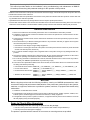
Warranty and Limitations of Liability
WARRANTY
OMRON's exclusive warranty is that the products are free from defects in materials and workmanship for a
period of one year (or other period if specified) from date of sale by OMRON.
OMRON MAKES NO WARRANTY OR REPRESENTATION, EXPRESS OR IMPLIED, REGARDING NONINFRINGEMENT, MERCHANTABILITY, OR FITNESS FOR PARTICULAR PURPOSE OF THE
PRODUCTS. ANY BUYER OR USER ACKNOWLEDGES THAT THE BUYER OR USER ALONE HAS
DETERMINED THAT THE PRODUCTS WILL SUITABLY MEET THE REQUIREMENTS OF THEIR
INTENDED USE. OMRON DISCLAIMS ALL OTHER WARRANTIES, EXPRESS OR IMPLIED.
LIMITATIONS OF LIABILITY
OMRON SHALL NOT BE RESPONSIBLE FOR SPECIAL, INDIRECT, OR CONSEQUENTIAL DAMAGES,
LOSS OF PROFITS OR COMMERCIAL LOSS IN ANY WAY CONNECTED WITH THE PRODUCTS,
WHETHER SUCH CLAIM IS BASED ON CONTRACT, WARRANTY, NEGLIGENCE, OR STRICT
LIABILITY.
In no event shall the responsibility of OMRON for any act exceed the individual price of the product on which
liability is asserted.
IN NO EVENT SHALL OMRON BE RESPONSIBLE FOR WARRANTY, REPAIR, OR OTHER CLAIMS
REGARDING THE PRODUCTS UNLESS OMRON'S ANALYSIS CONFIRMS THAT THE PRODUCTS
WERE PROPERLY HANDLED, STORED, INSTALLED, AND MAINTAINED AND NOT SUBJECT TO
CONTAMINATION, ABUSE, MISUSE, OR INAPPROPRIATE MODIFICATION OR REPAIR.
1
No. 6182
Application Considerations
SUITABILITY FOR USE
OMRON shall not be responsible for conformity with any standards, codes, or regulations that apply to the
combination of products in the customer's application or use of the products.
At the customer's request, OMRON will provide applicable third party certification documents identifying
ratings and limitations of use that apply to the products. This information by itself is not sufficient for a
complete determination of the suitability of the products in combination with the end product, machine,
system, or other application or use.
The following are some examples of applications for which particular attention must be given. This is not
intended to be an exhaustive list of all possible uses of the products, nor is it intended to imply that the uses
listed may be suitable for the products:
• Outdoor use, uses involving potential chemical contamination or electrical interference, or conditions or
uses not described in this manual.
• Nuclear energy control systems, combustion systems, railroad systems, aviation systems, medical
equipment, amusement machines, vehicles, safety equipment, and installations subject to separate
industry or government regulations.
• Systems, machines, and equipment that could present a risk to life or property.
Please know and observe all prohibitions of use applicable to the products.
NEVER USE THE PRODUCTS FOR AN APPLICATION INVOLVING SERIOUS RISK TO LIFE OR
PROPERTY WITHOUT ENSURING THAT THE SYSTEM AS A WHOLE HAS BEEN DESIGNED TO
ADDRESS THE RISKS, AND THAT THE OMRON PRODUCTS ARE PROPERLY RATED AND INSTALLED
FOR THE INTENDED USE WITHIN THE OVERALL EQUIPMENT OR SYSTEM.
PROGRAMMABLE PRODUCTS
OMRON shall not be responsible for the user's programming of a programmable product, or any
consequence thereof.
2
No. 6182
Disclaimers
CHANGE IN SPECIFICATIONS
Product specifications and accessories may be changed at any time based on improvements and other
reasons.
It is our practice to change model numbers when published ratings or features are changed, or when
significant construction changes are made. However, some specifications of the products may be changed
without any notice. When in doubt, special model numbers may be assigned to fix or establish key
specifications for your application on your request. Please consult with your OMRON representative at any
time to confirm actual specifications of purchased products.
DIMENSIONS AND WEIGHTS
Dimensions and weights are nominal and are not to be used for manufacturing purposes, even when
tolerances are shown.
PERFORMANCE DATA
Performance data given in this manual is provided as a guide for the user in determining suitability and does
not constitute a warranty. It may represent the result of OMRON's test conditions, and the users must
correlate it to actual application requirements. Actual performance is subject to the OMRON Warranty and
Limitations of Liability.
ERRORS AND OMISSIONS
The information in this manual has been carefully checked and is believed to be accurate; however, no
responsibility is assumed for clerical, typographical, or proofreading errors, or omissions.
3
Notice:
OMRON products are manufactured for use according to proper procedures by a qualified
operator and only for the purposes described in this manual.
The following conventions are used to indicate and classify precautions in this manual. Always heed the information provided with them. Failure to heed precautions can result in injury to people or damage to property.
!
DANGER
Indicates an imminently hazardous situation which, if not avoided, will result in death
or serious injury.
!
WARNING
Indicates a potentially hazardous situation which, if not avoided, could result in death
or serious injury.
! Caution
Indicates a potentially hazardous situation which, if not avoided, may result in minor
or moderate injury, or property damage.
OMRON Product References
All OMRON products are capitalized in this manual. The word “Unit” is also capitalized when
it refers to an OMRON product, regardless of whether or not it appears in the proper name
of the product.
The abbreviation “Ch,” which appears in some displays and on some OMRON products, often means “word” and is abbreviated “Wd” in documentation in this sense.
The abbreviation “PC” means Programmable Controller and is not used as an abbreviation
for anything else.
Visual Aids
The following headings appear in the left column of the manual to help you locate different
types of information.
Note Indicates information of particular interest for efficient and convenient operation of the product.
OMRON, 1994
All rights reserved. No part of this publication may be reproduced, stored in a retrieval system, or transmitted, in any form, or by any means, mechanical, electronic, photocopying,
recording, or otherwise, without the prior written permission of OMRON.
No patent liability is assumed with respect to the use of the information contained herein.
Moreover, because OMRON is constantly striving to improve its high-quality products, the
information contained in this manual is subject to change without notice. Every precaution
has been taken in the preparation of this manual. Nevertheless, OMRON assumes no responsibility for errors or omissions. Neither is any liability assumed for damages resulting
from the use of the information contained in this publication.
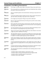
General Warnings
Observe the following warnings when using the OMNUC Servomotor and Servo Driver.
This manual may include illustrations of the product with protective covers removed in order
to describe the components of the product in detail. Make sure that these protective covers
are on the product before use.
Consult your OMRON representative when using the product after a long period of storage.
!
WARNING
Always connect the frame ground terminals of the Servo Driver and the Servomotor
to a class-3 ground (to 100 Ω or less). Not connecting to a class-3 ground may result
in electric shock.
!
WARNING
Do not touch the inside of the Servo Driver. Doing so may result in electric shock.
!
WARNING
Do not remove the front cover, terminal covers, cables, Parameter Units, or optional
items while the power is being supplied. Doing so may result in electric shock.
!
WARNING
Operation, maintenance, or inspection must be performed by authorized personnel.
Not doing so may result in electric shock or injury.
!
WARNING
Wiring or inspection must be performed at least 5 minutes after turning off the power
supply. Doing so may result in electric shock.
!
WARNING
Do not damage, press, or put excessive stress or heavy objects on the cables. Doing
so may result in electric shock.
!
WARNING
Do not touch the rotating parts of the Servomotor under operation. Doing so may
result in injury.
!
WARNING
Do not modify the product. Doing so may result in injury or damage to the product.
! Caution
Use the Servomotors and Servo Drivers in a specified combination. Doing so may
result in fire or damage to the products.
! Caution
Do not store or install in the following places. Doing so may result in fire or damage to
the Product.
S Locations subject to direct sunlight.
S Locations subject to temperatures or humidity outside the range specified in the
specifications.
S Locations subject to condensation as the result of severe changes in temperature.
S Locations subject to corrosive or flammable gases.
S Locations subject to dust (especially iron dust) or salts.
S Locations subject to shock or vibration.
S Locations subject to exposure to water, oil, or chemicals.
! Caution
Do not touch the Servo Driver radiator or Servomotor while the power is being supplied or soon after the power is turned off. Doing so may result in a skin burn due to
the hot surface.
Storage and Transportation Precautions
! Caution
Do not hold by the cables or motor shaft while transporting the product. Doing so
may result in injury or malfunction.
! Caution
Do not place any load exceeding the figure indicated on the product. Doing so may
result in injury or malfunction.
! Caution
Use the motor eye-bolts only for transporting the Motor. Using them for transporting
the machinery may result in injury or malfunction.
Installation and Wiring Precautions
! Caution
Do not step on or place a heavy object on the product. Doing so may result in injury.
! Caution
Do not cover the inlet or outlet ports and prevent any foreign objects from entering
the product. Doing so may result in fire.
! Caution
Be sure to install the product in the correct direction. Not doing so may result in malfunction.
! Caution
Provide the specified clearances between the Servo Driver and the control panel or
with other devices. Not doing so may result in fire or malfunction.
! Caution
Do not apply any strong impact. Doing so may result in malfunction.
! Caution
Be sure to wire correctly and securely. Not doing so may result in motor runaway,
injury, or malfunction.
! Caution
Be sure that all the mounting screws, terminal screws, and cable connector screws
are tightened to the torque specified in the relevant manuals. Incorrect tightening
torque may result in malfunction.
! Caution
Use crimp terminals for wiring. Do not connect bare stranded wires directly to terminals. Connection of bare stranded wires may result in burning.
! Caution
Always use the power supply voltage specified in the User’s Manual. An incorrect
voltage may result in malfunction or burning.
! Caution
Take appropriate measures to ensure that the specified power with the rated voltage
and frequency is supplied. Be particularly careful in places where the power supply
is unstable. An incorrect power supply may result in malfunction.
! Caution
Install external breakers and take other safety measures against short-circuiting in
external wiring. Insufficient safety measures against short-circuiting may result in
burning.
! Caution
Provide an appropriate stopping device on the machine side to secure safety. (A
holding brake is not a stopping device for securing safety.) Not doing so may result in
injury.
! Caution
Provide an external emergency stopping device that allows an instantaneous stop of
operation and power interruption. Not doing so may result in injury.
! Caution
Take appropriate and sufficient countermeasures when installing systems in the following locations:
S Locations subject to static electricity or other forms of noise.
S Locations subject to strong electromagnetic fields and magnetic fields.
S Locations subject to possible exposure to radioactivity.
S Locations close to power supplies.
Operation and Adjustment Precautions
! Caution
Check the newly set parameters for proper execution before actually running them.
Not doing so may result in equipment damage.
! Caution
Do not make any extreme adjustments or setting changes. Doing so may result in
unstable operation and injury.
! Caution
Separate the Servomotor from the machine, check for proper operation, and then
connect to the machine. Not doing so may cause injury.
! Caution
When an alarm occurs, remove the cause, reset the alarm after confirming safety,
and then resume operation. Not doing so may result in injury.
! Caution
Do not come close to the machine immediately after resetting momentary power
interruption to avoid an unexpected restart. (Take appropriate measures to secure
safety against an unexpected restart.) Doing so may result in injury.
! Caution
Do not use the built-in brake of the Servomotor for ordinary braking. Doing so may
result in malfunction.
Maintenance and Inspection Precautions
!
WARNING
! Caution
Do not attempt to disassemble, repair, or modify any Units. Any attempt to do so may
result in malfunction, fire, or electric shock.
Resume operation only after transferring to the new Unit the contents of the data
required for operation. Not doing so may result in an unexpected operation.
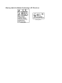
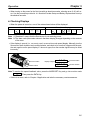
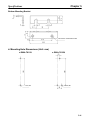
Warning Labels
Warning labels are pasted on the product as shown in the following illustration. Be sure to
follow the instructions given there.
Warning labels
Warning Labels for Non-conforming Models
Warning label 2
Warning label 1
Warning Labels for Models Conforming to EC Directives
Warning label 2
Warning label 1
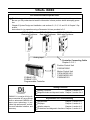
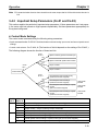
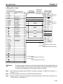
VISUAL INDEX
For users who wish to operate soon.
- The following portions of this manual provide the minimum information required for operation.
Be sure you fully understand at least the information in these portions before attempting operation.
Chapter 2 System Design and Installation, and sections 3-1, 3-2, 3-3, and 3-5 of Chapter 3 Operation.
Instructions for jog operation using a Parameter Unit are provided in 3-5.
OMNUC N115
One-axis Positioner
OMNUC N116
OMNUC U43/U45
One-axis Positioner Multi-axis Positioner
Analog input
Controller Connecting Cable
Chapter 5: 5-3-1
SYSMAC CS1
SYSMAC C/CV
Programmable Controller
Position Control Unit
C500-NC222-E
Motion Control Unit
CS1W-MC221/421
CV500-MC221/421
C200H-MC221
Setting Functions
- Setting Functions:
Chapter 3, section 3-3
- Magnetic brake and dynamic brake: Chapter 3, section 3-4-2
OMNUC U is a series of fully software-controlled AC servo drivers
built on advanced OMRON software servo technology. It provides high performance, a sensitive man-machine interface, and
economy.
Adjustments and Troubleshooting
- Adjustments:
Chapter 3, section 3-6
- Displays:
Chapter 4, section 4-1
- Monitor outputs:
Chapter 4, section 4-2
- Protections and diagnostic functions:Chapter 4, section 4-3
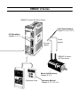
OMNUC U Series
OMNUC U-series AC Servo Driver
Cable Specifications
Chapter 5: 5-3-2, 5-3-3
I/O Operations
Chapter 5: 5-1-3
Encoder
signals
Power
signals
OMNUC U-series
AC Servomotor
Motor Specifications
Chapter 5: 5-2
Parameter Units
Operation Method
Chapter 3: 3-1, 3-2, 3-3
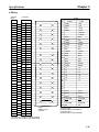
Table of Contents
Chapter 1. Introduction . . . . . . . . . . . . . . . . . . . . . . . . . . . . . . . . . . . . .
1-1
1-2
1-3
1-4
Features . . . . . . . . . . . . . . . . . . . . . . . . . . . . . . . . . . . . . . . . . . . . . . . . . . . . . . . . . . . . . . . . . . .
System Configuration . . . . . . . . . . . . . . . . . . . . . . . . . . . . . . . . . . . . . . . . . . . . . . . . . . . . . . . .
Servo Driver Nomenclature . . . . . . . . . . . . . . . . . . . . . . . . . . . . . . . . . . . . . . . . . . . . . . . . . . . .
Applicable Standards and Models . . . . . . . . . . . . . . . . . . . . . . . . . . . . . . . . . . . . . . . . . . . . . . .
1-4-1 UL/cUL Standards . . . . . . . . . . . . . . . . . . . . . . . . . . . . . . . . . . . . . . . . . . . . . . . . . . . .
1-4-2 EC Directives . . . . . . . . . . . . . . . . . . . . . . . . . . . . . . . . . . . . . . . . . . . . . . . . . . . . . . . .
Chapter 2. System Design and Installation . . . . . . . . . . . . . . . . . . . . . .
2-1 Installation . . . . . . . . . . . . . . . . . . . . . . . . . . . . . . . . . . . . . . . . . . . . . . . . . . . . . . . . . . . . . . . . .
2-1-1 External Dimensions (Unit: mm) . . . . . . . . . . . . . . . . . . . . . . . . . . . . . . . . . . . . . . . . .
2-1-2 Installation Conditions . . . . . . . . . . . . . . . . . . . . . . . . . . . . . . . . . . . . . . . . . . . . . . . . .
2-2 Wiring Products Conforming to UL/cUL
and Wiring Products Not Conforming to Any Standards . . . . . . . . . . . . . . . . . . . . . . . . . . . . .
2-2-1 Wiring to an OMRON Controller . . . . . . . . . . . . . . . . . . . . . . . . . . . . . . . . . . . . . . . . .
2-2-2 Connector–Terminal Conversion Unit . . . . . . . . . . . . . . . . . . . . . . . . . . . . . . . . . . . . .
2-2-3 Wiring Terminal Blocks . . . . . . . . . . . . . . . . . . . . . . . . . . . . . . . . . . . . . . . . . . . . . . . .
2-2-4 Wiring for Noise Resistance . . . . . . . . . . . . . . . . . . . . . . . . . . . . . . . . . . . . . . . . . . . . .
2-2-5 Peripheral Device Connection Examples . . . . . . . . . . . . . . . . . . . . . . . . . . . . . . . . . . .
2-3 Wiring Products Conforming to EC Directives . . . . . . . . . . . . . . . . . . . . . . . . . . . . . . . . . . . . .
2-3-1 Wiring to an OMRON Controller . . . . . . . . . . . . . . . . . . . . . . . . . . . . . . . . . . . . . . . . .
2-3-2 Wiring Terminal Blocks . . . . . . . . . . . . . . . . . . . . . . . . . . . . . . . . . . . . . . . . . . . . . . . .
2-3-3 Wiring Products Conforming to EMC Directives . . . . . . . . . . . . . . . . . . . . . . . . . . . .
2-3-4 Peripheral Device Connection Examples . . . . . . . . . . . . . . . . . . . . . . . . . . . . . . . . . . .
Chapter 3. Operation . . . . . . . . . . . . . . . . . . . . . . . . . . . . . . . . . . . . . . .
3-1 Operational Procedure . . . . . . . . . . . . . . . . . . . . . . . . . . . . . . . . . . . . . . . . . . . . . . . . . . . . . . . .
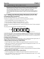
3-2 Turning On Power and Checking Displays . . . . . . . . . . . . . . . . . . . . . . . . . . . . . . . . . . . . . . . .
3-2-1 Items to Check Before Turning On Power . . . . . . . . . . . . . . . . . . . . . . . . . . . . . . . . . .
3-2-2 Turning On Power and Confirming the Display . . . . . . . . . . . . . . . . . . . . . . . . . . . . .
3-3 Using Parameter Units . . . . . . . . . . . . . . . . . . . . . . . . . . . . . . . . . . . . . . . . . . . . . . . . . . . . . . . .
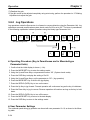
3-3-1 Parameter Unit Keys and Functions . . . . . . . . . . . . . . . . . . . . . . . . . . . . . . . . . . . . . . .
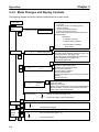
3-3-2 Modes and Changing Modes . . . . . . . . . . . . . . . . . . . . . . . . . . . . . . . . . . . . . . . . . . . .
3-3-3 Mode Changes and Display Contents . . . . . . . . . . . . . . . . . . . . . . . . . . . . . . . . . . . . . .
3-4 Initial Settings: Setup Parameters . . . . . . . . . . . . . . . . . . . . . . . . . . . . . . . . . . . . . . . . . . . . . . .
3-4-1 Setting and Checking Setup Parameters (Cn-01, 02) . . . . . . . . . . . . . . . . . . . . . . . . . .
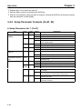
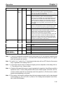
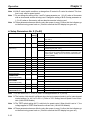
3-4-2 Setup Parameter Contents (Cn-01, 02) . . . . . . . . . . . . . . . . . . . . . . . . . . . . . . . . . . . . .
3-4-3 Important Setup Parameters (Cn-01 and Cn-02) . . . . . . . . . . . . . . . . . . . . . . . . . . . . .
3-5 Setting Functions: User Parameters . . . . . . . . . . . . . . . . . . . . . . . . . . . . . . . . . . . . . . . . . . . . . .
3-5-1 Setting and Checking User Parameters (Cn-03 to 29) . . . . . . . . . . . . . . . . . . . . . . . . .
3-5-2 User Parameter Chart . . . . . . . . . . . . . . . . . . . . . . . . . . . . . . . . . . . . . . . . . . . . . . . . . .
3-5-3 Internal Speed Control Setting . . . . . . . . . . . . . . . . . . . . . . . . . . . . . . . . . . . . . . . . . . .
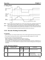
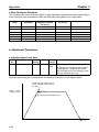
3-5-4 Soft Start Function (Speed Control, Internally Set Speed Control) . . . . . . . . . . . . . . .
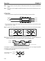
3-5-5 Encoder Dividing Function (INC) . . . . . . . . . . . . . . . . . . . . . . . . . . . . . . . . . . . . . . . .
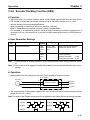
3-5-6 Encoder Dividing Function (ABS) . . . . . . . . . . . . . . . . . . . . . . . . . . . . . . . . . . . . . . . .
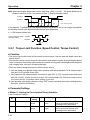
3-5-7 Torque Limit Function (Speed Control, Torque Control) . . . . . . . . . . . . . . . . . . . . . .
3-5-8 Torque Feed-forward Function (Speed Control with HA/LA/V/W Models) . . . . . . . .
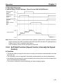
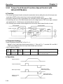
3-5-9 Brake Interlock (For Motors with Brakes) . . . . . . . . . . . . . . . . . . . . . . . . . . . . . . . . . .
3-6 Trial Operation . . . . . . . . . . . . . . . . . . . . . . . . . . . . . . . . . . . . . . . . . . . . . . . . . . . . . . . . . . . . . .
3-6-1 Preparations for Trial Operation . . . . . . . . . . . . . . . . . . . . . . . . . . . . . . . . . . . . . . . . . .
3-6-2 Jog Operations . . . . . . . . . . . . . . . . . . . . . . . . . . . . . . . . . . . . . . . . . . . . . . . . . . . . . . .
3-7 Making Adjustments . . . . . . . . . . . . . . . . . . . . . . . . . . . . . . . . . . . . . . . . . . . . . . . . . . . . . . . . .
3-7-1 Auto-tuning . . . . . . . . . . . . . . . . . . . . . . . . . . . . . . . . . . . . . . . . . . . . . . . . . . . . . . . . . .
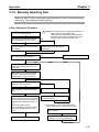
3-7-2 Manually Adjusting Gain . . . . . . . . . . . . . . . . . . . . . . . . . . . . . . . . . . . . . . . . . . . . . . .
3-7-3 Adjusting Command Offset . . . . . . . . . . . . . . . . . . . . . . . . . . . . . . . . . . . . . . . . . . . . .
Table of Contents
3-8 Regenerative Energy Absorption . . . . . . . . . . . . . . . . . . . . . . . . . . . . . . . . . . . . . . . . . . . . . . . .
3-8-1 Calculating Regenerative Energy . . . . . . . . . . . . . . . . . . . . . . . . . . . . . . . . . . . . . . . . .
3-8-2 Servo Driver Absorbable Regenerative Energy . . . . . . . . . . . . . . . . . . . . . . . . . . . . . .
3-8-3 Absorption of Regenerative Energy with the External Regeneration Resistor
(Models Conforming to UL/cUL Standards and Models
Not Conforming to Any Standards) . . . . . . . . . . . . . . . . . . . . . . . . . . . . . . . . . . . . . . .
3-8-4 Processing Regenerative Energy with Multiple Axes
(Models Conforming to EC Directives) . . . . . . . . . . . . . . . . . . . . . . . . . . . . . . . . . . . .
Chapter 4. Application . . . . . . . . . . . . . . . . . . . . . . . . . . . . . . . . . . . . . .
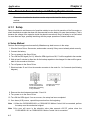
4-1 Absolute Encoder Setup and Battery Replacement . . . . . . . . . . . . . . . . . . . . . . . . . . . . . . . . .
4-1-1 Setup . . . . . . . . . . . . . . . . . . . . . . . . . . . . . . . . . . . . . . . . . . . . . . . . . . . . . . . . . . . . . . .
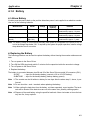
4-1-2 Battery . . . . . . . . . . . . . . . . . . . . . . . . . . . . . . . . . . . . . . . . . . . . . . . . . . . . . . . . . . . . . .
4-2 Using Displays . . . . . . . . . . . . . . . . . . . . . . . . . . . . . . . . . . . . . . . . . . . . . . . . . . . . . . . . . . . . . .
4-2-1 Display Functions . . . . . . . . . . . . . . . . . . . . . . . . . . . . . . . . . . . . . . . . . . . . . . . . . . . . .
4-2-2 Status Display Mode . . . . . . . . . . . . . . . . . . . . . . . . . . . . . . . . . . . . . . . . . . . . . . . . . . .
4-2-3 Monitor Mode (Un-) . . . . . . . . . . . . . . . . . . . . . . . . . . . . . . . . . . . . . . . . . . . . . . . . . . .
4-2-4 Checking Servomotor Parameters (Cn-00 Set to 04) . . . . . . . . . . . . . . . . . . . . . . . . . .
4-3 Using the Monitor Output . . . . . . . . . . . . . . . . . . . . . . . . . . . . . . . . . . . . . . . . . . . . . . . . . . . . .
4-4 Protective and Diagnostic Functions . . . . . . . . . . . . . . . . . . . . . . . . . . . . . . . . . . . . . . . . . . . . .
4-4-1 Alarm Displays and Alarm Code Outputs . . . . . . . . . . . . . . . . . . . . . . . . . . . . . . . . . .
4-4-2 Alarm Output . . . . . . . . . . . . . . . . . . . . . . . . . . . . . . . . . . . . . . . . . . . . . . . . . . . . . . . .
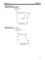
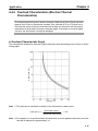
4-4-3 Overload Characteristics (Electron Thermal Characteristics) . . . . . . . . . . . . . . . . . . .
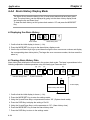
4-4-4 Alarm History Display Mode . . . . . . . . . . . . . . . . . . . . . . . . . . . . . . . . . . . . . . . . . . . .
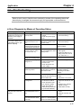
4-5 Troubleshooting . . . . . . . . . . . . . . . . . . . . . . . . . . . . . . . . . . . . . . . . . . . . . . . . . . . . . . . . . . . . .
4-6 Periodic Maintenance . . . . . . . . . . . . . . . . . . . . . . . . . . . . . . . . . . . . . . . . . . . . . . . . . . . . . . . .
Chapter 5. Specifications . . . . . . . . . . . . . . . . . . . . . . . . . . . . . . . . . . . .
5-1 Servo Driver Specifications . . . . . . . . . . . . . . . . . . . . . . . . . . . . . . . . . . . . . . . . . . . . . . . . . . . .
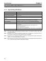
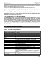
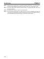
5-1-1 General Specifications . . . . . . . . . . . . . . . . . . . . . . . . . . . . . . . . . . . . . . . . . . . . . . . . .
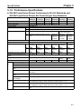
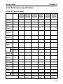
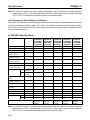
5-1-2 Performance Specifications . . . . . . . . . . . . . . . . . . . . . . . . . . . . . . . . . . . . . . . . . . . . .
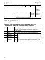
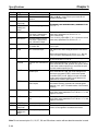
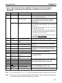
5-1-3 I/O Specifications . . . . . . . . . . . . . . . . . . . . . . . . . . . . . . . . . . . . . . . . . . . . . . . . . . . . .
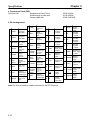
5-1-4 Parameter Specifications . . . . . . . . . . . . . . . . . . . . . . . . . . . . . . . . . . . . . . . . . . . . . . .
5-2 Servomotor Specifications . . . . . . . . . . . . . . . . . . . . . . . . . . . . . . . . . . . . . . . . . . . . . . . . . . . . .
5-2-1 General Specifications . . . . . . . . . . . . . . . . . . . . . . . . . . . . . . . . . . . . . . . . . . . . . . . . .
5-2-2 Performance Specifications . . . . . . . . . . . . . . . . . . . . . . . . . . . . . . . . . . . . . . . . . . . . .
5-2-3 Allowable Loads on Servomotor Shafts . . . . . . . . . . . . . . . . . . . . . . . . . . . . . . . . . . . .
5-2-4 Encoder Specifications . . . . . . . . . . . . . . . . . . . . . . . . . . . . . . . . . . . . . . . . . . . . . . . . .
5-3 Cable Specifications . . . . . . . . . . . . . . . . . . . . . . . . . . . . . . . . . . . . . . . . . . . . . . . . . . . . . . . . .
5-3-1 Controller Connecting Cable . . . . . . . . . . . . . . . . . . . . . . . . . . . . . . . . . . . . . . . . . . . .
5-3-2 Encoder Cable . . . . . . . . . . . . . . . . . . . . . . . . . . . . . . . . . . . . . . . . . . . . . . . . . . . . . . . .
5-3-3 Power Cables . . . . . . . . . . . . . . . . . . . . . . . . . . . . . . . . . . . . . . . . . . . . . . . . . . . . . . . .
5-4 Parameter Unit Specifications . . . . . . . . . . . . . . . . . . . . . . . . . . . . . . . . . . . . . . . . . . . . . . . . . .
5-5 Regeneration Unit Specifications . . . . . . . . . . . . . . . . . . . . . . . . . . . . . . . . . . . . . . . . . . . . . . .
5-6 Front-surface Mounting Bracket Specifications . . . . . . . . . . . . . . . . . . . . . . . . . . . . . . . . . . . .
Chapter 6. Supplementary Materials . . . . . . . . . . . . . . . . . . . . . . . . . .
6-1
6-2
6-3
6-4
Connection Examples . . . . . . . . . . . . . . . . . . . . . . . . . . . . . . . . . . . . . . . . . . . . . . . . . . . . . . . .
Encoder Dividing Ratios and Speeds when Connected to OMRON Controllers . . . . . . . . . . .
OMNUC U-series Standard Models . . . . . . . . . . . . . . . . . . . . . . . . . . . . . . . . . . . . . . . . . . . . .
Parameter Setting Forms . . . . . . . . . . . . . . . . . . . . . . . . . . . . . . . . . . . . . . . . . . . . . . . . . . . . . .
6-4-1 Parameters when Using an Incremental Encoder . . . . . . . . . . . . . . . . . . . . . . . . . . . . .
6-4-2 Parameters when Using an Absolute Encoder . . . . . . . . . . . . . . . . . . . . . . . . . . . . . . .
1
Chapter 1
Introduction
1-1
1-2
1-3
1-4
Features
System Configuration
Servo Driver Nomenclature
Applicable Standards and Models
Chapter 1
Introduction
1-1
Features
OMNUC AC Servo Drivers control the power supplied to AC Servomotors with analog input signals to
perform precise speed control. There are 7 types of AC Servomotors: 30-W, 50-W, 100-W, 200-W,
300-W, 400-W, and 750-W.
H Motor Output Capacity
AC Servomotors with the following output capacities are available.
S For 200/230-VAC (170 to 253 V) single-phase, 50/60-Hz Input
30 W, 50 W, 100 W, 200 W, 400 W, and 750 W
S For 100/115-VAC (85 to 127 V) single-phase, 50/60-Hz Input
30 W, 50 W, 100 W, 200 W, and 300 W
The Servomotors also come with and without brakes, and with and without keys on the straight
shaft. Servomotors that conform to EC Directives, however, are available only with keys on the
shaft.
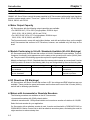
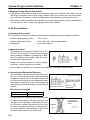
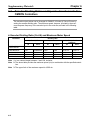
H Models Conforming to UL/cUL Standards Available (UL/cUL Markings)
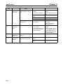
AC Servomotors and Servo Drivers that conform to UL/cUL Standards are now available. Their performance, functionality, and appearance are the same as the conventional U-series (HA/LA) models. They are useful for obtaining approvals required for specific applications.
Models conforming to UL/cUL Standards have the same product names as conventional U-series
(HA/LA) models. As shown in the following table, they are distinguished by the manufacturing date.
Model
Models not conforming to
any standards
Models conforming to
UL/cUL Standards
Manufacturing date
Before April 1998
Type
H/L, HA/LA
After May 1998
HA/LA
Remarks
Production of H/L models
discontinued.
UL/cUL markings are
attached to products.
H EC Directives (CE Markings)
AC Servomotors and Servo Drivers that conform to EC low-voltage and EMC directives are now
available. These provide the same performance and functions as the rest of the U Series (HA/LA),
and will aid in obtaining specifications.
H Motors with Incremental or Absolute Encoders
The following encoders are available on the AC Servomotors.
S Incremental encoders with 2,048 pulses/rotation
S Absolute encoders with 1,024 pulses/rotation and a maximum number of rotations of ±99,999.
Select the best encoder for your application.
If a Servomotor with an absolute encoder is used, it can be combined with a CV500-MC221/421 or
C200H-MC221 Motion Control Unit to build an absolute encoder system, eliminating the need for
origin searches to reduce startup time.
1-2
Introduction
Chapter 1
H Control Functions
Any one of the following 8 control modes can be selected in the parameter settings.
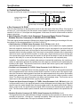
• Speed Control
Controls the speed of the Servomotor very precisely with an analog input signal (the speed command voltage).
The ratio between the command voltage and number of revolutions can be set in the parameters.
The setting range is ±2 to 10 V/rated number of revolutions. (With the factory setting the rated number of revolutions is reached at ±10 V.)
• Speed Control with Position-lock Function
This control mode adds the position-lock function to the speed control mode.
When the position-lock command (PLOCK) is input, the control mode switches from speed control
to position control and the motor is servo-locked so temperature drift won’t cause slight rotation.
The number of revolutions caused by position-lock can be set in the parameters.
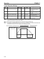
• Internal Speed Control Settings (Servo-lock when Stopped)
The speed of the motor is controlled with the three speeds (No. 1, No. 2, and No. 3 internal speed
settings) set in the parameters.
This mode is effective for simple position control or speed-switching operation.
• Internal Speed Control Settings (Position-lock when Stopped) HA/LA/V/W Models
This control mode has the same operation as the internal speed control settings described above,
except that a position loop is established when the Servomotor is stopped, so the stopped position
can be maintained even when an external force is applied.
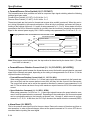
• Internal Speed Control Settings (Servo-lock when Stopped) + Speed Control HA/LA/V/W Models
Speed control can be performed with the internal speed settings as well as analog inputs (the
speed command voltage).
With the internal speed settings, the Servomotor will be servo-locked when it is stopped.
• Internal Speed Control Settings (Position-lock when Stopped) + Speed Control HA/LA/V/W Models
Speed control can be performed with the internal speed settings as well as analog inputs (the
speed command voltage).
With the internal speed settings, the Servomotor will be position-locked when it is stopped.
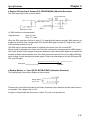
• Torque Control 1
Controls the output torque of the Servomotor with an analog input signal (the torque command voltage).
The ratio between the command voltage and the torque can be set in the parameters.
The setting range is ±1 to 10 V/rated torque. (With the factory setting the rated torque is reached at
±3 V.)
• Torque Control 2
This control mode allows the user to switch between torque control and speed control.
Speed control is enabled when the torque/speed control switch (TVSEL) is ON, and torque control
is enabled when TVSEL is OFF.
The ratio between the command voltage and torque and the ratio between the command voltage
and the number of revolutions can both be set in the parameters.
1-3
Chapter 1
Introduction
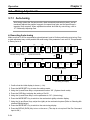
H Auto-tuning
The gain can be adjusted automatically when the responsiveness has been selected to match the
rigidity of the mechanical system. The auto-tuning feature automatically finds the optimum adjustment to match the load, with no need for difficult operations.
H Monitor
Displays the driver’s operating status on the Parameter Unit.
The following items can be monitored: speed feedback, speed commands, torque commands,
number of pulses from the U-phase edge, electrical angle, and the internal status (bit display).
H Jog Operation
Forward/Reverse motor operation can be controlled from the Parameter Unit. Rotational speed can
be set in the parameters.
H Automatic Adjustment of Control Offset (Speed Control and Torque
Control)
The offsets of the speed command input and torque command input can be adjusted automatically.
H Encoder Resolution Setting
The encoder signal output from the driver can be set anywhere within the following ranges.
S Incremental encoders: 16 to 2,048 pulses/revolution
S Absolute encoders:
16 to 1,024 pulses/revolution
H Software Start Function (Speed Control)
This function causes the motor to be started/stopped in the preset acceleration/deceleration times,
allowing a simple position control system to be constructed without a Positioner or Host Controller.
The acceleration and deceleration times are set separately, and the setting range is 0 to 10 s for
each.
H Reverse Mode
Forward/Reverse commands can be switched in the parameters, without changing the wiring to the
motor or encoder.
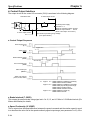
H Brake Interlock Output
Outputs a timing signal interlocked with the motor’s ON/OFF status and rotational speed. The holding brake of a motor with a brake can be operated reliably.
H Overtravel Sequence
An overtravel sequence compatible with the system can be selected. There are three deceleration
methods available: dynamic brake deceleration, free-run deceleration, and emergency-stop torque
deceleration (parameter setting).
1-4
Introduction
Chapter 1
H Computer Monitor Software (HA/LA/V/W Models)
The special Servo Driver Communications Software allows parameter setting, speed and current
monitoring, I/O monitoring, auto-tuning, and jog operations to be performed from a personal computer. It is also possible to perform multiple-axis communications that set the parameters and monitor the operation of several drivers. Refer to the Computer Monitor Software Instruction Manual
(I513) for OMNUC U-series Servo Drivers for more details.
1-5
Chapter 1
Introduction
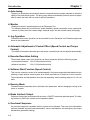
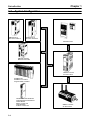
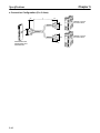
1-2
System Configuration
OMNUC N115
One-axis Positioner
OMNUC N116
One-axis Positioner
Parameter Units
OMNUC U43/U45
Multi-axis Controller
OMNUC U-series
AC Servo Driver
SYSMAC CS1
SYSMAC C/CV-series
Programmable Controller
CS1W-MC221/CS1W-MC421
CV500-MC221/CV500-MC421
C200H-MC221
Motion Control Unit
C500-NC222-E
Position Control Unit
1-6
OMNUC U-series
AC Servomotor
Chapter 1
Introduction
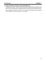
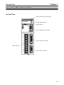
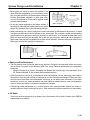
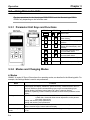
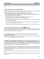
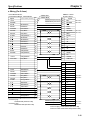
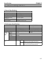
1-3
Servo Driver Nomenclature
H Front View
CN4: Connector for monitor output
Power supply indicator
Alarm indicator
CN3: Parameter Unit connector
CN1: Control I/O connector
Terminal block
CN2: Encoder connector
1-7
Chapter 1
Introduction
1-4
Applicable Standards and Models
1-4-1 UL/cUL Standards
H Applicable Standards
Standard
UL
cUL
Product
AC Servo Driver
AC Servomotor
AC Servo Driver
AC Servomotor
Applicable Standard
UL508C
UL1004
cUL C22.2 No. 14
cUL C22.2 No.100
File No.
E179149
E179189
E179149
E179189
Remarks
Power conversion equipment
Electric motors
Industrial equipment
Motor and generators
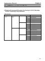
H Applicable Models
Power supply
pp y
200 VAC
100 VAC
AC Servomotors
AC Servo Drivers
R88D-UAjjHA
(See note 1.)
R88D-UAjjLA
(See note 1.)
With incremental encoder
With absolute encoder
R88M-Ujjj30HA-j
R88M-Ujjj30TA-j
(See note 2.) (See note 3.)
(See note 2.) (See note 3.)
R88M-Ujjj30LA-j
R88M-Ujjj30SA-j
(See note 2.) (See note 3.)
(See note 2.) (See note 3.)
Note 1. Maximum output current: for example, “04” means approx. 4 A.
Note 2. Motor capacity: for example, “100” means 100 W.
Note 3. Optional specifications
None: Straight shaft without keys and without brake
B:
Straight shaft without keys and with brake
S1:
Straight shaft with keys and without brake
BS1: Straight shaft with keys and with brake
Note 4. UL/cUL Standards apply to models manufactured after May 1998.
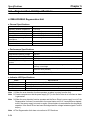
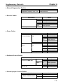
1-4-2 EC Directives
H Applicable Standards
EC Directive
Low voltage
Product
AC Servo Driver
Directive
EN61010-1
EMC
AC Servomotor
AC Servo Driver
AC Servomotor
IEC34-1, -5, -8, -9
EN55011 class A
group 1
EN50082-2
Remarks
Safety requirements for electrical equipment for
measurement, control, and laboratory use.
Rotating electrical machines.
Limits and methods of measurement of radio
disturbance characteristics of industrial,
scientific, and medical (ISM) radio-frequency
equipment.
Electromagnetic compatibility generic immunity
standard, Part 2 Industrial environment.
Note Installation under the conditions specified in 2-3-3 Wiring Products Conforming to EMC Directives is required to conform to EMC Directives.
1-8
Chapter 1
Introduction
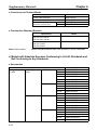
H Applicable Models
Power supply
pp y
AC Servo Drivers
200 VAC
R88D-UAjjV
100 VAC
R88D-UAjjW
AC Servomotors
With incremental encoder
R88M-Ujjj30VA-j
(See note.)
R88M-Ujjj30WA-j
(See note.)
With absolute encoder
R88M-Ujjj30XA-j
(See note.)
R88M-Ujjj30YA-j
(See note.)
Note Optional specifications (shaft profile: straight shaft with keys)
S1:
Straight shaft with keys and without brake
BS1: Straight shaft with keys and with brake
1-9
2
Chapter 2
System Design and Installation
2-1
2-2
2-3
Installation
Wiring Products Conforming to UL/cUL and
Wiring Products Not Conforming to Any Standards
Wiring Products Conforming to EC Directives
System Design and Installation
Chapter 2
Installation and Wiring Precautions
! Caution
Do not step on or place a heavy object on the product. Doing so may result in injury.
! Caution
Do not cover the inlet or outlet ports and prevent any foreign objects from entering
the product. Doing so may result in fire.
! Caution
Be sure to install the product in the correct direction. Not doing so may result in malfunction.
! Caution
Provide the specified clearances between the Servo Driver and the control panel or
with other devices. Not doing so may result in fire or malfunction.
! Caution
Do not apply any strong impact. Doing so may result in malfunction.
! Caution
Be sure to wire correctly and securely. Not doing so may result in motor runaway,
injury, or malfunction.
! Caution
Be sure that all the mounting screws, terminal screws, and cable connector screws
are tightened to the torque specified in the relevant manuals. Incorrect tightening
torque may result in malfunction.
! Caution
Use crimp terminals for wiring. Do not connect bare stranded wires directly to terminals. Connection of bare stranded wires may result in burning.
! Caution
Always use the power supply voltage specified in the User’s Manual. An incorrect
voltage may result in malfunction or burning.
! Caution
Take appropriate measures to ensure that the specified power with the rated voltage
and frequency is supplied. Be particularly careful in places where the power supply
is unstable. An incorrect power supply may result in malfunction.
! Caution
Install external breakers and take other safety measures against short-circuiting in
external wiring. Insufficient safety measures against short-circuiting may result in
burning.
! Caution
Provide an appropriate stopping device on the machine side to secure safety. (A
holding brake is not a stopping device for securing safety.) Not doing so may result in
injury.
! Caution
Provide an external emergency stopping device that allows an instantaneous stop of
operation and power interruption. Not doing so may result in injury.
! Caution
Take appropriate and sufficient countermeasures when installing systems in the following locations:
S Locations subject to static electricity or other forms of noise.
S Locations subject to strong electromagnetic fields and magnetic fields.
S Locations subject to possible exposure to radioactivity.
S Locations close to power supplies.
2-2
Chapter 2
System Design and Installation
2-1
Installation
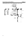
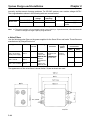
2-1-1 External Dimensions (Unit: mm)
H AC Servo Drivers Conforming to UL/cUL Standards and AC
Servomotors Not Conforming to Any Standards
D R88D-UA02H(A)/-UA03H(A)/-UA04H(A)/-UA08H(A) (200 VAC, 30 to 200 W)
R88D-UA03L(A)/-UA04L(A)/-UA10L(A) (100 VAC, 30 to 100 W)
5
4
Installation dimensions
55
5
130
45
(5)
45
(6)
Three, M4
Two,
6 dia.
160
149
149
R3
5
(165)
6
D R88D-UA12H(A) (200 VAC, 400 W) and R88D-UA12L(A) (100 VAC, 200 W)
5
4
75
130
(6)
Installation dimensions
5
60
(5)
60
Two,
6 dia.
160
Three, M4
149
149
R3
(165)
5
6
2-3
Chapter 2
System Design and Installation
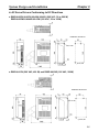
D R88D-UA20H(A) (200 VAC, 750 W) and R88D-UA15LA (100 VAC, 300 W)
3.5
7
105
130
90
(8)
6
Two, 6 dia.
160
149
Two, R3
5
(165)
6
6
90
Installation
dimensions
Four, M4
149
2-4
Chapter 2
System Design and Installation
H AC Servo Drivers Conforming to EC Directives
D R88D-UA02V/-UA03V/-UA04V/-UA08V (200 VAC, 30 to 200 W)
R88D-UA03W/-UA04W/-UA10W (100 VAC, 30 to 100W)
Installation dimensions
Two, 6 dia.
Three, M4
D R88D-UA12V (200 VAC, 400 W) and R88D-UA12W (100 VAC, 200W)
Installation dimensions
Two, 6 dia.
Three, M4
2-5
Chapter 2
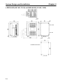
System Design and Installation
D R88D-UA20V (200 VAC, 750 W) and R88D-UA15W (100 VAC, 300W)
Two, 6 dia.
Two, R3
Installation dimensions
Four, M4
2-6
Chapter 2
System Design and Installation
H Regeneration Unit
D R88A-RG08UA
(15) (6)
25
Dia.: 6
Installation dimensions
Two, M4
160 130 149
149
R3
15
5
6
(18.5)
130
25
50
2-7
Chapter 2
System Design and Installation
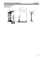
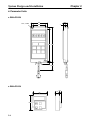
H Parameter Units
D R88A-PR02U
Two, 4.5 dia.
18.5
63
50
7
125 135
(8)
1000
D R88A-PR03U
54
57.5
2-8
15
6.9
Chapter 2
System Design and Installation
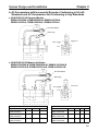
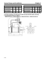
H AC Servomotors with Incremental Encoders Conforming to UL/cUL
Standards and AC Servomotors Not Conforming to Any Standards
D 30-W/50-W/100-W Standard Models:
R88M-U03030HA, R88M-U05030HA, R88M-U10030HA
R88M-U03030LA, R88M-U05030LA, R88M-U10030LA
300±30
35
Encoder adapter
Motor plug
6.5
18
14 dia.
300±30
6
6h6 dia.
2.5
Two, 4.3 dia.
30h7 dia.
17
9.5
5
Four, R3.7
6
40
46 dia.
33
40
LL
25
L
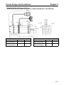
D 30-W/50-W/100-W Models with Brake:
R88M-U03030HA-B, R88M-U05030HA-B, R88M-U10030HA-B
R88M-U03030LA-B, R88M-U05030LA-B, R88M-U10030LA-B
300±30
35
Encoder adapter
Motor plug
21
14 dia.
2.5
Two, 4.3 dia.
30h7 dia.
17
5
33
Four, R3.7
4
46 dia.
40
9.5
6.5
6h6 dia.
300±30
LB
40
LL
25
L
Standard Models
Model
L
Models with Brake
LL
S
Model
L
LL
LB
S
R88M-U03030HA
R88M-U03030LA
94.5
69.5
6
R88M-U03030HA-B
R88M-U03030LA-B
126
101
31.5
6
R88M-U05030HA
R88M-U05030LA
102.0
77.0
6
R88M-U05030HA-B
R88M-U05030LA-B
133.5
108.5
31.5
6
R88M-U10030HA
R88M-U10030LA
119.5
94.5
8
R88M-U10030HA-B
R88M-U10030LA-B
160
135
40.5
8
2-9
Chapter 2
System Design and Installation
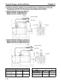
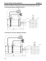
H AC Servomotors with Incremental Encoders Conforming to UL/cUL
Standards and Not Conforming to Any Standards (Contd.)
D 200-W/300-W/400-W Standard Models:
R88M-U20030HA, R88M-U40030HA
R88M-U20030LA, R88M-U30030LA
300±30
35
Encoder adapter
Motor plug
21
14 dia.
12
3
Four, 5.5 dia.
50h7 dia.
17
6
Four, R5.3
70 dia.
60
7
14h6 dia.
300±30
5.2
34
60
LL
30
L
D 200-W/300-W/400-W Models with Brake:
R88M-U20030HA-B, R88M-U40030HA-B
R88M-U20030LA-B, R88M-U30030LA-B
300±30
35
Encoder adapter
Motor plug
21
14 dia.
Four,
5.5 dia.
50h7 dia.
3
34
Four, R5.3
60
12
6
70 dia.
7
17
5.5
14h6 dia.
300±30
5.2
60
39.5
LL
30
L
Standard Models
Model
Models with Brake
L
LL
Model
L
LL
R88M-U20030HA
R88M-U20030LA
126.5
96.5
R88M-U20030HA-B
R88M-U20030LA-B
166
136
R88M-U40030HA
R88M-U30030LA
154.5
124.5
R88M-U40030HA-B
R88M-U30030LA-B
194
164
2-10
Chapter 2
System Design and Installation
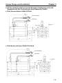
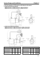
H AC Servomotors with Incremental Encoders Conforming to UL/cUL
Standards and Not Conforming to Any Standards (Contd.)
D 750-W Standard Models: R88M-U75030HA
300±30
35
Encoder adapter
Motor plug
21
14 dia.
300±30
8
15
3
Four, R8.2
35
80
90 dia.
16h6 dia.
Four, 7 dia.
70h7 dia.
8
17
5.2
34
80
145
40
185
D 750-W Models with Brake: R88M-U75030HA-B
300±30
35
Encoder adapter
Motor plug
21
14 dia.
300±30
8
15
Four, R8.2
3
35
34
44.5
90 dia.
Four, 7 dia.
80
70h7 dia.
8
16h6 dia.
17
5.2
80
189.5
40
229.5
2-11
Chapter 2
System Design and Installation
H AC Servomotors with Absolute Encoders Conforming to UL/cUL
Standards and Not Conforming to Any Standards
D 30-W/50-W/100-W Standard Models:
R88M-U03030TA, R88M-U05030TA, R88M-U10030TA
R88M-U03030SA, R88M-U05030SA, R88M-U10030SA
Encoder adapter
Motor plug
14 dia.
Sh6 dia.
Four, R3.7
Two, 4.3 dia.
46 dia.
53 dia.
30h7 dia.
D 30-W/50-W/100-W Models with Brake:
R88M-U03030TA-B, R88M-U05030TA-B, R88M-U10030TA-B
R88M-U03030SA-B, R88M-U05030SA-B, R88M-U10030SA-B
Encoder adapter
Motor plug
14 dia.
Sh6 dia.
Four, R3.7
Two, 4.3 dia.
46 dia.
30h7 dia.
53 dia.
Standard Models
Model
L
Models with Brake
LL
S
Model
L
LL
LB
S
R88M-U03030TA
R88M-U03030SA
117.5
92.5
6
R88M-U03030TA-B
R88M-U03030SA-B
149
124
31.5
6
R88M-U05030TA
R88M-U05030SA
125
100
6
R88M-U05030TA-B
R88M-U05030SA-B
156.5
131.5
31.5
6
R88M-U10030TA
R88M-U10030SA
142.5
117.5
8
R88M-U10030TA-B
R88M-U10030SA-B
183
158
40.5
8
2-12
Chapter 2
System Design and Installation
H AC Servomotors with Absolute Encoders Conforming to UL/cUL
Standards and Not Conforming to Any Standards (Contd.)
D 200-W/300-W/400-W Standard Models:
R88M-U20030TA, R88M-U40030TA, R88M-U20030SA, R88M-U30030SA
Encoder adapter
Motor plug
14 dia.
14h6 dia.
Four, R5.3
Four, 5.5.dia.
70 dia.
50h7 dia.
D 200-W/300-W/400-W Models with Brake:
R88M-U20030TA-B, R88M-U40030TA-B, R88M-U20030SA-B, U30030SA-B
Encoder adapter
Motor plug
14 dia.
14h6 dia.
Four, 5.5.dia.
Four, R5.3
70 dia.
50h7 dia.
Standard Models
Model
Models with Brake
L
LL
Model
L
LL
R88M-U20030TA
R88M-U20030SA
147.5
117.5
R88M-U20030TA-B
R88M-U20030SA-B
187
157
R88M-U40030TA
R88M-U30030SA
175.5
145.5
R88M-U40030TA-B
R88M-U30030-SA-B
215
185
2-13
Chapter 2
System Design and Installation
H AC Servomotors with Absolute Encoders Conforming to UL/cUL
Standards and Not Conforming to Any Standards (Contd.)
D 750-W Standard Models: R88M-U75030TA
Encoder adapter
Motor plug
14 dia.
Four, R8.2
Four, 7 dia.
16h6 dia.
90 dia.
70h7 dia.
D 750-W Models with Brake: R88M-U75030TA-B
Encoder adapter
Motor plug
14 dia.
Four, R8.2
Four, 7 dia.
16h6 dia.
90 dia.
70h7 dia.
2-14
Chapter 2
System Design and Installation
H AC Servomotors, EC Directives with Incremental Encoders
D 30-W/50-W/100-W Standard Models:
R88M-U03030VA-S1, R88M-U05030VA-S1, R88M-U10030VA-S1
R88M-U03030WA-S1, R88M-U05030WA-S1, R88M-U10030WA-S1
14 dia.
Four, R3.7
Two, 4.3 dia.
Sh6 dia.
46 dia.
30h7 dia.
D 30-W/50-W/100-W Models with Brake:
R88M-U03030VA-BS1, R88M-U05030VA-BS1, R88M-U10030VA-BS1
R88M-U03030WA-BS1, R88M-U05030WA-BS1, R88M-U10030WA-BS1
14 dia.
Four, R3.7
Two, 4.3 dia.
Sh6 dia.
46 dia.
30h7 dia.
2-15
Chapter 2
System Design and Installation
Standard Models
Model
L
LL
R88M-U03030VA-S1
94.5
69.5
R88M-U03030WAS1
R88M-U05030VA-S1
102.0
77.0
R88M-U05030WA-S1
R88M-U10030VA-S1
119.5
94.5
R88M-U10030WA-S1
Models with Brake
Model
L
LL
R88M-U03030VA-BS1
126
101
R88M-U03030WA-BS1
R88M-U05030VA-BS1
133.5 108.5
R88M-U05030WA-BS1
R88M-U10030VA-BS1
160
135
R88M-U10030WA-BS1
S
6
6
8
LB
31.5
S
6
31.5
6
40.5
8
H AC Servomotors, EC Directives with Incremental Encoders (Contd.)
D 200-W/300-W/400-W Standard Models:
R88M-U20030VA-S1, R88M-U40030VA-S1, R88M-U20030WA-S1, R88M-U30030WA-S1
14 dia.
Four, 5.5 dia.
14h6 dia.
70 dia.
50h7 dia.
2-16
Four, R5.3
Chapter 2
System Design and Installation
D 200-W/300-W/400-W Models with Brake:
R88M-U20030VA-BS1, R88M-U40030VA-BS1, R88M-U20030WA-BS1, U30030WA-BS1
14 dia.
Four, 5.5 dia.
Four, R5.3
14h6 dia.
70 dia.
50h7 dia.
Standard Models
Model
R88M-U20030VA-S1
R88M-U20030WA-S1
R88M-U40030VA-S1
R88M-U30030WA-S1
Models with Brake
L
LL
126.5
96.5
154.5
124.5
Model
R88M-U20030VA-BS1
R88M-U20030WA-BS1
R88M-U40030VA-BS1
R88M-U30030WA-BS1
L
LL
166
136
194
164
2-17
Chapter 2
System Design and Installation
H AC Servomotors, EC Directives with Incremental Encoders (Contd.)
D 750-W Standard Models: R88M-U75030VA-S1
14 dia.
Four, R8.2
Four, 7 dia.
16h6 dia.
90 dia.
70h7 dia.
D 750-W Models with Brake: R88M-U75030VA-BS1
14 dia.
Four, R8.2
Four, 7 dia.
16h6 dia.
90 dia.
70h7 dia.
2-18
Chapter 2
System Design and Installation
H AC Servomotors, EC Directives with Absolute Encoders
D 30-W/50-W/100-W Standard Models:
R88M-U03030XA-S1, R88M-U05030XA-S1, R88M-U10030XA-S1
R88M-U03030YA-S1, R88M-U05030YA-S1, R88M-U10030YA-S1
14 dia.
Four, R3.7
Sh6 dia.
Two, 4.3 dia.
46 dia.
53 dia.
30h7 dia.
D 30-W/50-W/100-W Models with Brake:
R88M-U03030XA-BS1, R88M-U05030XA-BS1, R88M-U10030XA-BS1
R88M-U03030YA-BS1, R88M-U05030YA-BS1, R88M-U10030YA-BS1
14 dia.
Four, R3.7
Sh6 dia.
Two, 4.3 dia.
46 dia.
53 dia.
30h7 dia.
Standard Models
Model
R88M-U03030XA-S1
R88M-U03030YAS1
R88M-U05030XA-S1
R88M-U05030YA-S1
R88M-U10030XA-S1
R88M-U10030YA-S1
Models with Brake
L
117.5
LL
92.5
6
S
125
100
6
142.5
117.5
8
Model
R88M-U03030XA-BS1
R88M-U03030YA-BS1
R88M-U05030XA-BS1
R88M-U05030YA-BS1
R88M-U10030XA-BS1
R88M-U10030YA-BS1
L
149
LL
124
LB
31.5
S
6
156.5
131.5
31.5
6
183
158
40.5
8
2-19
Chapter 2
System Design and Installation
H AC Servomotors, EC Directives with Absolute Encoders (Contd.)
D 200-W/300-W/400-W Standard Models:
R88M-U20030XA-S1, R88M-U40030XA-S1, R88M-U20030YA-S1, R88M-U30030YA-S1
14 dia.
14h6 dia.
Four, R5.3
Four, 5.5 dia.
70 dia.
50h7 dia.
D 200-W/300-W/400-W Models with Brake:
R88M-U20030XA-BS1, R88M-U40030XA-BS1, R88M-U20030YA-BS1, U30030YA-BS1
14 dia.
14h6 dia.
Four, 5.5 dia.
Four, R5.3
70 dia.
50h7 dia.
Standard Models
Model
Models with Brake
L
LL
Model
L
LL
R88M-U20030XA-S1
R88M-U20030YA-S1
147.5
117.5
R88M-U20030XA-BS1
R88M-U20030YA-BS1
187
157
R88M-U40030XA-S1
R88M-U30030YA-S1
175.5
145.5
R88M-U40030XA-BS1
R88M-U30030YA-BS1
215
185
2-20
Chapter 2
System Design and Installation
H AC Servomotors, EC Directives with Absolute Encoders (Contd.)
D 750-W Standard Models: R88M-U75030XA-S1
14 dia.
Four, R8.2
Four, 7 dia.
16h6 dia.
90 dia.
80
70h7 dia.
D 750-W Models with Brake: R88M-U75030XA-BS1
14 dia.
Four, R8.2
Four, 7 dia.
16h6 dia.
90 dia.
70h7 dia.
2-21
Chapter 2
System Design and Installation
H Shaft Dimensions of Motors With Keys (Incremental and Absolute)
Standard U-series AC Servomotors do not have keys on the shafts. The dimensions of motors with keys
(produced on order) are shown below. Motors with keys are indicated by adding “-S1” to the end of the
model number. Key slots are based on JIS B1301-1976.
D 30-W/50-W Models
Standard: R88M-U03030jj-S1, R88M-U05030jj-S1
With Brake: R88M-U03030jj-BS1, R88M-U05030jj-BS1
14
Dia.: 6h6
1.2
2
2
D 100-W Models
Standard: R88M-U10030jj-S1
With Brake: R88M-U10030jj-BS1
14
Dia.: 8h6
1.8
3
3
D 200-W/300-W/400-W Models
Standard: R88M-U20030jj-S1, R88M-U40030jj-S1, R88M-U30030jj-S1
With Brake: R88M-U20030jj-BS1, R88M-U40030jj-BS1, R88M-U30030jj-BS1
20
Dia.: 14h6
3
5
5
D 750-W Models
Standard: R88M-U75030jj-S1
With Brake: R88M-U75030jj-BS1
30
Dia.: 16h6
3
5
5
2-22
Chapter 2
System Design and Installation
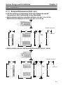
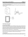
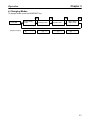
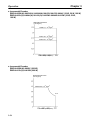
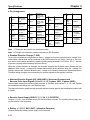
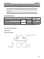
2-1-2 Installation Conditions
H AC Servo Drivers
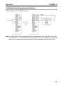
D Space Around Drivers
• Install Servo Drivers according to the dimensions shown in the following illustration to ensure proper
heat dispersion and convection inside the panel. Also install a fan for circulation if Servo Drivers are
installed side by side to prevent uneven temperatures from developing inside the panel.
• Mount the Servo Drivers vertically (so that the model number and writing can be read).
ÉÉÉÉÉÉÉÉÉÉÉÉÉÉÉÉÉÉÉÉÉÉ
ÉÉÉÉÉÉÉÉÉÉÉÉÉÉÉÉÉÉÉÉÉÉ
ÉÉÉÉÉÉÉÉÉÉÉÉÉÉÉÉÉÉÉÉÉÉ
ÉÉÉÉÉÉÉÉÉÉÉÉÉÉÉÉÉÉÉÉÉÉ
ÉÉÉÉÉÉÉÉÉÉÉÉÉÉÉÉÉÉÉÉÉÉ
ÉÉÉÉÉÉÉÉÉÉÉÉÉÉÉÉÉÉÉÉÉÉ
ÉÉÉÉÉÉÉÉÉÉÉÉÉÉÉÉÉÉÉÉÉÉ
ÉÉÉÉÉÉÉÉÉÉÉÉÉÉÉÉÉÉÉÉÉÉ
ÉÉÉÉÉÉÉÉÉÉÉÉÉÉÉÉÉÉÉÉÉÉ
ÉÉÉÉÉÉÉÉÉÉÉÉÉÉÉÉÉÉÉÉÉÉ
ÉÉÉÉÉÉÉÉÉÉÉÉÉÉÉÉÉÉÉÉÉÉ
ÉÉÉÉÉÉÉÉÉÉÉÉÉÉÉÉÉÉÉÉÉÉ
ÉÉÉÉÉÉÉÉÉÉÉÉÉÉÉÉÉÉÉÉÉÉ
Servo Driver
Servo Driver
W
30 mm min.
50 mm min.
Fan
Servo Driver
Fan
Side of Unit
W
W = 10 mm min.
50 mm min.
D Operating Environment
Be sure that the environment in which Servo Drivers are operated meets the following conditions.
• Ambient operating temperature:
0°C to +55°C
• Ambient operating humidity:
35% to 85% (RH, with no condensation)
• Atmosphere:
No corrosive gases.
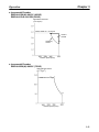
D Ambient Temperature
• Servo Drivers should be operated in environments in which there is minimal temperature rise to
maintain a high level of reliability.
• Temperature rise in any Unit installed in a closed space, such as a control box, will cause the ambient
temperature to rise inside the entire closed space. Use a fan or a air conditioner to prevent the ambient temperature of the Servo Driver from exceeding 55°C.
• Unit surface temperatures may rise to as much as 30°C above the ambient temperature. Use heatresistant materials for wiring, and keep separate any devices or wiring that are sensitive to heat.
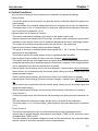
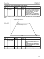
• The service life of a Servo Driver is largely determined by the temperature around the internal electrolytic capacitors. The service life of an electrolytic capacitor is affected by a drop in electrolytic volume and an increase in internal resistance, which can result in overvoltage alarms, malfunctioning
due to noise, and damage to individual elements. If a Servo Driver is always operated at the maximum ambient temperature of 55°C, then a service life of approximately 50,000 hours can be expected. A drop of 10°C in the ambient temperature will double the expected service life.
2-23
Chapter 2
System Design and Installation
D Keeping Foreign Objects Out of Units
• Place a cover over the Units or take other preventative measures to prevent foreign objects, such as
drill filings, from getting into the Units during installation. Be sure to remove the cover after installation is complete. If the cover is left on during operation, heat buildup may damage the Units.
• Take measures during installation and operation to prevent foreign objects such as metal particles,
oil, machining oil, dust, or water from getting inside of Servo Drivers.
H AC Servomotors
D Operating Environment
Be sure that the environment in which the Servomotor is operated meets the following conditions.
• Ambient operating temperature:
0°C to +40°C
• Ambient operating humidity:
20% to 80% (RH, with no condensation)
• Atmosphere:
No corrosive gases.
D Impact and Load
• The Servomotor is resistant to impacts of up to 10 G
{98 m/s2}. Do not subject it to heavy impacts or loads
during transport, installation, or positioning. In addition, do not hold onto the encoder, cable, or connector areas when transporting it.
• Always use a pulley remover to remove pulleys,
couplings, or other objects from the shaft.
• Secure cables so that there is no impact or load placed on the cable connector areas.
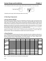
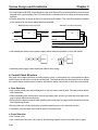
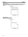
D Connecting to Mechanical Systems
• The axial loads for Servomotors are specified in section 5-2-4. If an axial load greater than that specified
is applied to a Servomotor, it will reduce the service
life of the motor bearings and may damage the motor
shaft. When connecting to a load, use couplings that
can sufficiently absorb mechanical eccentricity and
variation.
Ball screw center line
Motor shaft center line
Shaft core
displacement
Recommended Coupling
Name
Oldham coupling
Maker
Myghty Co., Ltd
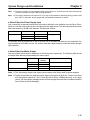
• For spur gears, an extremely large radial load may
be applied depending on the gear precision. Use
spur gears with a high degree of accuracy (for example, JIS class 2: normal line pitch error of 6 µm max.
for a pitch circle diameter of 50 mm). If the gear precision is not adequate, allow backlash to ensure that
no radial load is placed on the motor shaft.
2-24
Backlash
Adjust backlash
by adjusting the
distance between
shafts.
Chapter 2
System Design and Installation
• Bevel gears will cause a load to be applied in the
thrust direction depending on the structural precision, the gear precision, and temperature changes.
Provide appropriate backlash or take other measures to ensure that no thrust load is applied which
exceeds specifications.
• Do not put rubber packing on the flange surface. If
the flange is mounted with rubber packing, the motor
flange may separate due to the tightening strength.
Bevel gear
Make moveable.
• When connecting to a V-belt or timing belt, consult the maker for belt selection and tension. A radial
load twice the belt tension will be placed on the motor shaft. Do not allow a radial load exceeding
specifications to be placed on the motor shaft due to belt tension. If an excessive radial load is applied, the motor shaft may be damaged. Set up the structure so that the radial load can be adjusted. A
large radial load may also be applied as a result of belt vibration. Attach a brace and adjust Servo
Driver gain so that belt vibration is minimized.
Pulley
Belt
Tension
Make adjustable.
Motor shaft
Load shaft
D Water and Drip Resistance
• The Servomotor does not have a water-proof structure. Except for the connector areas, the protective structure is covered by the following JEM (The Japan Electrical Manufacturers’ Association)
standards.
Models Conforming to UL/cUL Standards and Models Not Conforming to Any Standards: IP-42
EC Directive Models: IP-44 (except shaft penetration point)
• If the Servomotor is used in an environment in which condensation occurs, water may enter inside of
the encoder from the end surfaces of cables due to motor temperature changes. Either take measures to ensure that water cannot penetrate in this way, or use water-proof connectors. Even when
machinery is not in use, water penetration can be avoided by taking measures, such as keeping the
motor in servo-lock status, to minimize temperature changes.
• If machining oil with surfactants (e.g., coolant fluids) or their spray penetrate inside of the motor, insulation defects or short-circuiting may occur. Take measures to prevent machining oil penetration.
D Oil Seals
If the motor shaft is exposed to oil or grease, use a Servomotor with oil seals. (Contact your OMRON
representative for details.)
2-25
System Design and Installation
Chapter 2
D Other Precautions
• Do not apply commercial power directly to the Servomotor. The Servomotors run on synchronous
AC and use permanent magnets. Applying 3-phase power will burn out the motor coils.
• Do not carry the Servomotor by its cable, otherwise the cable may become disconnected or the cable
clamp may become damaged.
• Take measures to prevent the shaft from rusting. The shafts are coated with anti-rust oil when
shipped, but anti-rust oil or grease should also be applied when connecting the shaft to a load.
• Absolutely do not remove the encoder cover or take the motor apart. The magnet and the encoder
are aligned in the Servomotor. If they become misaligned, the motor will not operate.
2-26
Chapter 2
System Design and Installation
2-2
Wiring Products Conforming to UL/cUL and Wiring
Products Not Conforming to Any Standards
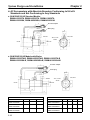
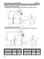
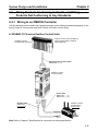
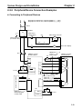
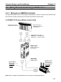
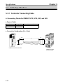
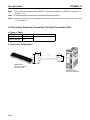
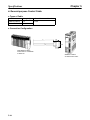
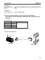
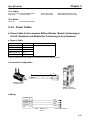
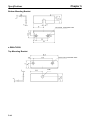
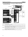
2-2-1 Wiring to an OMRON Controller
Use the dedicated control cables and a general-purpose control cable (purchased separately) to connect U-series AC Servomotors and Servo Drivers to Position Control Units.
H SYSMAC C/CV-series Position Control Units
SYSMAC C-series
Programmable Controller
Position Control Unit for SYSMAC Cseries Programmable Controllers
(C500-NC222-E)
General-purpose Control Cable
R88A-CPUjjjS
OMNUC U-series
AC Servo Driver
Power Cable
R88A-CAUjjjS
R88A-CAUjjjB
Encoder Cable
R88A-CRUjjjC
(Incremental)
OMNUC U-series
AC Servomotor
(Incremental)
Note Refer to Chapter 5 Specifications for connector and cable specifications.
2-27
Chapter 2
System Design and Installation
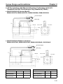
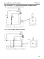
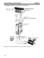
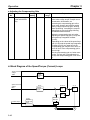
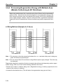
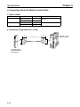
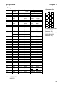
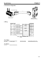
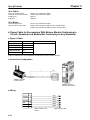
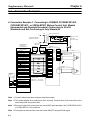
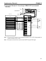
H SYSMAC CS1/C/CV-series Motion Control Units
SYSMAC CS1/C/CV-series
Programmable Controller
CS1W-MC221/CS1W-MC421
CV500-MC221/CV500-MC421
C200H-MC221
Motion Control Unit
Special Cables
R88A-CPUjjjM1 (for one-axis control)
R88A-CPUjjjM1 (for two-axis control)
OMNUC U-series
AC Servo Driver
Encoder Cable
R88A-CRUjjjC
(Incremental)
R88A-CSUjjjC
(Absolute)
Power Cable
R88A-CAUjjjS
R88A-CAUjjjB
Note Refer to Chapter 5 Specifications for connector and cable specifications.
2-28
OMNUC U-series
AC Servomotor
(Incremental, or
Absolute)
Chapter 2
System Design and Installation
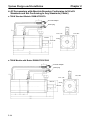
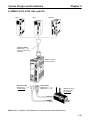
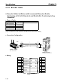
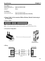
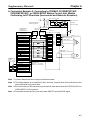
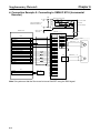
H OMNUC N115, N116, U43, and U45
N115
N116
U43/U45
Controller Cable
R88A-CPUjjjN
(for N115, N116, U43,
and U45)
OMNUC U-series
AC Servo Driver
Encoder Cable
R88A-CRUjjjC
(Incremental)
Power Cable
R88A-CAUjjjS
R88A-CAUjjjB
OMNUC U-series
AC Servomotor
(Incremental)
Note Refer to Chapter 5 Specifications for connector and cable specifications.
2-29
Chapter 2
System Design and Installation
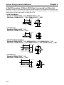
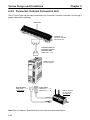
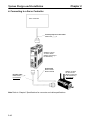
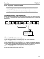
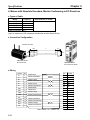
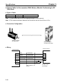
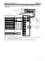
2-2-2 Connector–Terminal Conversion Unit
The AC Servo Driver can be easily connected to the Connector–Terminal Conversion Unit through a
special cable without soldering.
Controllers
XW2B-40F5-P
Connector–Terminal
Conversion Unit
Connector Cable for
Connector–Terminal
Conversion Unit
R88A-CTUjjjN
OMNUC U-series
AC Servo Driver
Encoder Cable
R88A-CRUjjjC
(Incremental)
Power Cable
R88A-CAUjjjS
R88A-CAUjjjB
OMNUC U-series
AC Servomotor
(Incremental)
Note Refer to Chapter 5 Specifications for connector and cable specifications.
2-30
Chapter 2
System Design and Installation
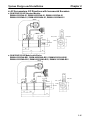
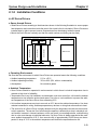
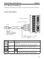
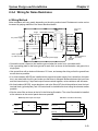
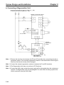
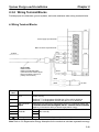
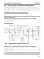
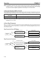
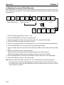
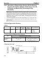
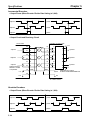
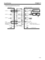
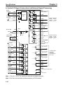
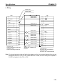
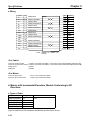
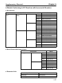
2-2-3 Wiring Terminal Blocks
Provide proper wire diameters, ground systems, and noise resistance when wiring terminal blocks.
H Wiring Terminal Blocks
Power supply input terminals
Main-circuit DC output terminals
Red
To Motor
White
Blue
Green
Power Cable
R88A-CAUjjjS
R88A-CAUjjjB (with brake)
(The broken lines indicate signal
lines for the brake. There is no
polarity on these lines.)
Black
Black
Terminal
Name
label
Power supply
R
input
T
P
N
U
V
W
Main circuit DC
output
24 VDC
Function
The commercial power supply input terminals for the main circuit and the
control circuitry.
y
R88D-UAjjH(A): Single-phase 200/230 VAC (170 to 253 V) 50/60 Hz
R88D-UAjjL(A): Single-phase 100/115 VAC (85 to 127 V) 50/60 Hz
The terminals for connecting
g Regeneration
g
Units ((R88A-RG08UA).
) Connect
these terminals when there is a high level off regenerative energy.
Motor connection Red
These are the output terminals to the Servomotor. Be careful to wire
terminals
i l
h
correctly.
l
White them
Blue
Frame ground
Green The ground terminal for both the motor output and power supply input. Ground to a class-3 ground (to 100 Ω or less) or better.
Note Refer to 3-8 Regenerative Energy Absorption for the methods to calculate regenerative energy.
2-31
Chapter 2
System Design and Installation
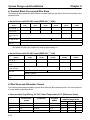
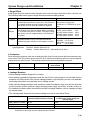
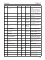
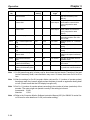
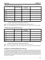
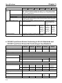
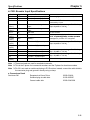
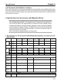
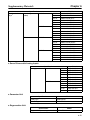
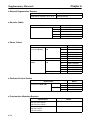
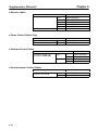
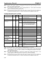
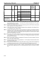
H Terminal Block Current and Wire Sizes
The following table shows the rated effective currents flowing to the Servo Driver and the sizes of the
electrical wires.
D Servo Drivers with 200-VAC Input (R88D-UAjjH(A))
Driver
(Watts)
R88D-UA02H(A)
(30 W)
R88D-UA03H(A) R88D-UA04H(A) R88D-UA08H(A) R88D-UA12H(A) R88D-UA20H(A)
(50 W)
(100 W)
(200 W)
(400 W)
(750 W)
Power supply input current (R, T)
1.3 A
1.5 A
2.5 A
4.0 A
6.0 A
11.0 A
Motor output current (U, V, W)
0.42 A
0.6 A
0.87 A
2.0 A
2.6 A
4.4 A
Power supply input terminal wire
size
0.75 mm2 or AWG 18 min.
1.25 mm2
2.0 mm2
Motor output
i l wire
i size
i
terminal
0.5 mm2 or AWG 20
Ground terminal
wire size
Use 2.0-mm2 external ground wires. Use the same wire as used for the motor output.
AWG 20 (see note) to AWG 18
Use OMRON standard cable. The applicable wire size for motor connectors is AWG22 to AWG18.
Note If the cable length is 15 meters or longer for a 750-W Servomotor, the momentary maximum torque at rotation speeds of 2,500 r/min or higher may drop by approximately 7%.
D Servo Drivers with 100-VAC Input (R88D-UAjjL(A))
Driver model
(Watts)
Power supply input current (R, T)
R88D-UA03L(A)
(30 W)
R88D-UA04L(A)
(50 W)
R88D-UA10L(A)
(100 W)
R88D-UA12L(A)
(200 W)
2.0 A
2.6 A
4.5 A
8.0 A
10.0 A
0.7 A
2.2 A
2.7 A
3.7 A
1.25 mm2
2 mm2
Motor output current (U, 0.63 A
V, W)
R88D-UA15LA
(300 W)
Power supply input terminal wire size
0.75 mm2 or AWG 18 min.
Motor output terminal
wire
i size
i
0.5 mm2 or AWG 20
AWG 20 to AWG 18
Use OMRON standard cable (AWG20). The applicable wire size for motor connectors is
AWG22 to AWG18.
Ground terminal wire
size
Use 2.0-mm2 external ground wires. Use the same wire as used for the motor output.
H Wire Sizes and Allowable Current
The following table shows allowable currents when there are three electrical wires. Use values equal to
or lower than the specified values.
D Heat-resistant Vinyl Wiring, UL1007, Rated Temperature 80°C (Reference Value)
AWG size
20
--18
16
2-32
Nominal crosssectional area
2)
(
(mm
0.5
0.75
0.9
1.25
Configuration
((wires/mm2)
19/0.18
30/0.18
37/0.18
50/0.18
Conductive
resistance
(Ω/k )
(Ω/km)
39.5
26.0
24.4
15.6
Allowable current (A) for
ambient temperature
40°C
6.6
8.8
9.0
12.0
50°C
5.6
7.0
7.7
11.0
60°C
4.5
5.5
6.0
8.5
Chapter 2
System Design and Installation
2-2-4 Wiring for Noise Resistance
H Wiring Method
Noise resistance will vary greatly depending on the wiring method used. Resistance to noise can be
increased by paying attention to the items described below.
Surge
Noise filter Contactor
MCCB absorber
X1
1
Servo Driver
R88DUjjjj
3
TB
R
TB
U
4
T
V
W
NF
AC power supply
2
E
Fuse
Servomotor
R88MUjjjjjj
Metal duct
M
CN2
RE
2 mm2 min.
3.5mm2
Class-3 ground
(to 100 Ω or less) Ground plate
Control board
ground
Controller power supply
Machine
ground
Thick power line
(3.5 mm2)
• Ground the motor’s frame to the machine ground when the motor is on a movable shaft.
• Use a grounding plate for the frame ground for each Unit, as shown in the illustration, and ground to a
single point.
• Use ground lines with a minimum thickness of 3.5 mm2, and arrange the wiring so that the ground lines
are as short as possible.
• If no-fuse breakers (MCCB) are installed at the top and the power supply line is wired from the lower
duct, use metal tubes for wiring and make sure that there is adequate distance between the input lines
and the internal wiring. If input and output lines are wired together, noise resistance will decrease.
• No-fuse breakers (MCCB), surge absorbers, and noise filters (NF) should be positioned near the input
terminal block (ground plate), and I/O lines should be isolated and wired using the shortest means
possible.
• Wire the noise filter as shown at the left in the following illustration. The noise filter should be installed
at the entrance to the control panel whenever possible.
Good: Separate input and output
1
AC input
Ground
3
NF
2
NO: Noise not filtered effectively
E
4
1
AC output
AC input
3
NF
2
E
4
Ground
AC output
2-33
Chapter 2
System Design and Installation
• Use twisted-pair cables for the power supply cables whenever possible, or bind the cables.
R
Driver
or
Driver
T
Binding
• Separate power supply cables and signal cables when wiring.
H Selecting Components
D No-fuse Breakers (MCCB)
When selecting no-fuse breakers, take into consideration the maximum output current and the inrush
current. The momentary maximum output for a servo system is approximately three times that of the
rated output, and a maximum output of three seconds can be executed. Therefore, select no-fuse
breakers with an operating time of at least five seconds at 300% of the rated maximum output. Generalpurpose and low-speed no-fuse breakers are generally suitable. Refer to the table in 2-2-3 Terminal
Block Wiring for the power supply input currents for each motor, and then add the current consumption
for the number of shafts, other controllers, etc., to make the selection.
The Servo Driver inrush current flows at a maximum of 50 A for 20 ms when 200 V is input. With lowspeed no-fuse breakers, a inrush current 7 to 8 times the rated current flows for 0.1 second. When making the selection, take into consideration the entire inrush current for the system.
D Surge Absorbers
Use surge absorbers to absorb surges from power supply input lines due to lightning, abnormal voltages, etc. When selecting surge absorbers, take into account the varistor voltage, the amount of surge
immunity, and the amount of energy resistance. For 200-VAC systems, use a varistor voltage of 470 V.
The surge absorbers shown in the following table are recommended.
Maker
Matsushita
El
Electric
i
Parts
Ishizuka
El
Electronics
i
Co
Co.
Okaya
Electric Ind.
Model
Varistor
voltage
Max. limit
voltage
Surge
immunity
Fuse
capacity
ERZV10D471(W)
ERZV14D471(W)
ERZV20D471(W)
ERZC20EK471(W)
Z10L471
Z15L471
Z21L471
Z25M471S
R.A.V
-781BWZ-2A
470 V
470 V
470 V
470 V
470 V
470 V
470 V
470 V
---
775 V
775 V
775 V
775 V
773 V
738 V
733 V
810 V
783 V
1,250 A
2,500 A
4,000 A
5,000A
1,000A
1,250 A
3,000 A
10,000 A
1,000 A
45 J
80 J
150 J
150 J
15 WSs
20 WSs
30 WSs
235 J
---
3 to 5 A
3 to 10 A
5 to 15 A
--3 to 5 A
3 to 5 A
5 to 10 A
-----
R.A.V
-781BXZ-2A
---
783 V
1,000 A
---
---
R.A.V
-401.621BYR-2
---
620 V
1,000 A
---
---
Note
1. The (W) Matsushita models are UL and CSA certified.
Note
2. Refer to manufacturers documentation for operating details.
2-34
Energy
resistance
Type
Disk
Block
Disk
Block
Block
Chapter 2
System Design and Installation
Note
3. The surge immunity is for a standard impulse current of 8/20 µs. If pulses are wide, either decrease the
current or change to a larger-capacity surge absorber.
Note
4. The energy resistance is the value for 2 ms. It may not be possible to retard high-energy pulses at less
than 700 V. In that case, absorb surges with an insulated transformer or reactor.
D Noise Filters for Power Supply Input
Use a noise filter to attenuate extraneous noise and to diminish noise radiation from the Servo Driver.
Select a noise filter with a load current of at least twice the rated current. The following table shows noise
filters that reduce by 40 dB noise between 200 kHz and 30 MHz.
Maker
Tokin
Model
LF-210N
LF-215N
LF-220N
Rated current
10 A
15 A
20 A
Remarks
For single-phase
g
To attenuate noise at frequencies of 200 kH or less, use an insulated transformer and a noise filter. For
high frequencies of 30 MHz or more, use a ferrite core and a high-frequency noise filter with a throughtype capacitor.
D Noise Filters for Motor Output
Use noise filters without built-in capacitors on the Servomotor output lines. The following table shows
the noise filters that are recommended for motor output.
Maker
Tokin
Fuji Electrochemical Co.
Model
LF-310KA
LF-320KA
ESD-R-47B
RN80UD
Rated
current
10 A
20 A
-----
Remarks
Three-phase block noise filter
EMI core for radiation noise
10-turn for radiation noise
Note 1. The Servomotor output lines cannot use the same noise filters used for power supplies.
Note 2. Typical noise filters are used with power supply frequencies of 50/60 Hz. If these noise filters
are connected to outputs of 7.8 to 11 KHz (the Servo Driver’s PWM frequency), a very large
(about 100 times larger) leakage current will flow through the noise filter’s condenser and the
Servo Driver could be damaged.
2-35
Chapter 2
System Design and Installation
D Surge Killers
Install surge killers for loads that have induction coils, such as relays, solenoids, brakes, clutches, etc.
The following table shows types of surge killers and recommended products.
Type
Diode
Features
Diodes are relatively small devices such as relays used
for loads when reset time is not an issue. The reset time
is increased because the surge voltage is the lowest
when power is cut off. Used for 24/48-VDC systems.
Thyristor
or
Varistor
Thyristor and varistor are used for loads when induction
coils are large, as in electromagnetic brakes, solenoids,
etc., and when reset time is an issue. The surge voltage
when power is cut off is approximately 1.5 times that of
the varistor.
Capacitor
+ resistor
Use capacitors and resistors for vibration absorption of
surge when power is cut off. The reset time can be
shortened by proper selection of the capacitor or resistor.
Recommended products
Use a fast-recovery diode with a
short reverse recovery time.
Fuji Electric Co., ERB44-06 or equivalent
Select varistor voltage as follows:
24-VDC system varistor:
100-VDC system varistor:
100-VAC system varistor:
200-VAC system varistor:
Okaya Electric Ind.
39 V
200 V
270 V
470 V
CR-50500 0.5 µF-50 Ω
CRE-50500 0.5 µF-50 Ω
S2-A-0
0.2 µF-500 Ω
Note Thyristors and varistors are made by the following companies. Refer to manufacturers documentation for
operating details. Thyristors: Ishizuka Electronics Co.
Varistors: Ishizuka Electronics Co., Matsushita Electric Parts
D Contactors
When selecting contactors, take into consideration the circuit’s inrush current and the momentary maximum current. The Servo Driver inrush current is 50 A, and the momentary maximum current is approximately twice the rated current. The following table shows the recommended contactors.
Maker
OMRON
Model
G6C-2BND
LY2-D
G7L-2A-BUBJ
J7AN-E3
LC1-D093A60
Rated current
10 A
10 A
25 A
15 A
11 A
Momentary maximum current
------120 A
200 A
Coil voltage
24 VDC
24 VDC
24 VDC, 200 to 240 VAC
24 VDC
24 VDC, 200/220 VAC,
200 to 240 VAC
D Leakage Breakers
• Select leakage breakers designed for inverters.
• Since switching operations take place inside the Servo Driver, high-frequency current leaks from the
armature of the Servomotor. With inverter leakage breakers, high-frequency current is not detected,
preventing the breaker from operating due to leakage current.
• When selecting leakage breakers, also remember to add the leakage current from devices other than
the Servomotor, such as machines using a switching power supply, noise filters, inverters, and so on.
• For detailed information about the selection methods of leakage breakers, refer to catalogs provided
by manufacturers.
2-36
System Design and Installation
Chapter 2
• The following table shows the Servomotor leakage currents for each Servo Driver.
Driver
Leakage current (direct)
(including high-frequency current)
Leakage current (resistor-capacitor,
in commercial power supply frequency range)
R88D-UA02H to -UA08H 80 mA
3 mA
R88D-UA12H
60 mA
4 mA
R88D-UA20H
110 mA
5 mA
Note 1. Leakage current values shown above are for motor power lines of 10 m or less. The values will change
depending on the length of power cables and the insulation.
Note
2. Leakage current values shown above are for normal temperatures and humidity. The values will
change depending on the temperature and humidity.
Note
3. Leakage current for 100-VAC-input Servomotors is approximately half that of the values shown above.
H Improving Encoder Cable Noise Resistance
The following encoder signals are used.
Incremental Encoders:
A, B, and S phase. The frequency for A- or B-phase signals is 154 kHz max.; the transmission speed for
S-phase signals is 616 kbps.
Absolute Encoders:
A, B, and Z phase, plus the absolute encoder signal. The frequency for A- or B-phase signals is 76.8 kHz
max.; the transmission speed for absolute encoder signals is 9.6 kbps.
Follow the wiring methods outlined below to improve encoder noise resistance.
• Be sure to use dedicated encoder cables.
• If lines are interrupted in the middle, be sure to connect them with connectors, making sure that the
cable insulation is not peeled off for more than 50 mm. In addition, be sure to use shielded wire.
• Do not coil cables. If cables are long and are coiled, mutual induction and inductance will increase and
will cause malfunctions. Be sure to use cables fully extended.
• When installing noise filters for encoder cables, use ferrite cores. The following table shows the recommended ferrite core models.
Maker
Tokin
TDK
Name
EMI core
Clamp filter
Model
ESD-QR-25-1
ZCAT2032-0930
ZCAT3035-1330
ZCAT2035-0930A
• Do not wire the encoder cable in the same duct as power cables and control cables for brakes, solenoids, clutches, and valves.
H Improving Control I/O Signal Noise Resistance
Position can be affected if control I/O signals are influenced by noise. Follow the methods outlined below for the power supply and wiring.
• Use completely separate power supplies for the control power supply (especially 24 VDC) and the
external operation power supply. In particular, be careful not to connect two power supply ground
wires. Install a noise filter on the primary side of the control power supply.
2-37
System Design and Installation
Chapter 2
• For speed and torque command input lines, be sure to use twisted-pair shielded cable, and connect
both ends of the shield wire to ground.
• If the control power supply wiring is long, noise resistance can be improved by adding 1-µF laminated
ceramic capacitors between the control power supply and ground at the Servo Driver input section
and the controller output section.
• For encoder output lines (A, B, and Z phases, plus the absolute encoder signal), be sure to use
twisted-pair shielded cable, and connect both ends of the shield wire to ground.
2-38
Chapter 2
System Design and Installation
2-2-5 Peripheral Device Connection Examples
H Connecting to Peripheral Devices
R
T
Single-phase, 200/230 VAC, 50/60 Hz (R88D-UjjjH(A))
Single-phase, 100/115 VAC, 50/60 Hz (R88D-UjjjL(A))
MCCB
1
E
3
2
NF
4
Noise filter
Main-circuit
power supply
Main-circuit connector
ON
OFF
1MC
Class-3 ground
(to 100 Ω or less)
1MC
Surge killer
X
X
1MC
PL
OMNUC U-series
AC Servo Driver
XB
OMNUC U-series
AC Servomotor
B
24VDC
R
U
T
V
CN1
X
R88D-CAUjjjS
(-CAUjjjB)
Power Cable
Servo error display
M
34 ALM
W
24 VDC
35 ALMCOM
Class-3 ground
(to 100 Ω or less)
User’s control device
X
CN1
CN2
R88A-CRUjjjC (Incremental)
R88A-CSUjjjC (Absolute)
Encoder Cable
E
CN1
R88A-CPUjjjS
General-purpose
Control Cable
BKIR 7
XB
24 VDC
OGND 10
2-39
Chapter 2
System Design and Installation
H Connecting a Regeneration Unit
Single-phase 200/230 VAC 50/60 Hz: R88D-UAjjH(A)
or 100/115 VAC 50/60 Hz: R88D-UAjjL(A)
OMNUC U-series Servo Driver
12 to 24 VDC
External
regeneration
resistor
R88A-RG08UA
Regeneration Unit
Note 1. Remove the short bar from between the RG and JP terminals when connecting external regeneration resistor. If the external regeneration resistor is connected without removing the
short bar, the internal circuitry will be damaged.
Note 2. Connect the external regeneration resistor to between the P and RG terminals.
Note 3. The Regeneration Unit does not conform to EC Directives.
Note 4. Connect the ALM output so that the power supply will be interrupted when the contacts are
opened. The Regeneration Unit may be damaged if it is used without including a power interruption sequence using the ALM output.
2-40
Chapter 2
System Design and Installation
2-3
Wiring Products Conforming to EC Directives
2-3-1 Wiring to an OMRON Controller
Use general-purpose control cable (purchased separately) to connect U-series AC Servomotors and
Servo Drivers (models conforming to EC Directives) to Motion Control Units.
H SYSMAC C/CV-series Motion Control Units
SYSMAC C/CV-series
Programmable Controller
Motion Control Unit
CV500-MC221/MC421
C200H-MC221
Dedicated Control Cables
R88A-CPUjjjM1 (for 1 axis)
R88A-CPUjjjM2 (for 2 axes)
OMNUC U-series
AC Servo Driver
(Model conforming to
EC Directives)
Power Cable
R88A-CAU001
R88A-CAU01B
Encoder Cable
R88A-CRUDjjjC
(Incremental)
R88A-CSUDjjjC
(Absolute)
OMNUC U-series
AC Servomotor
(Model conforming
to EC Directives)
(Incremental)
(Absolute)
Note Refer to Chapter 5 Specifications for connector and cable specifications.
2-41
Chapter 2
System Design and Installation
H Connecting to a Servo Controller
Servo Controller
General-purpose Control Cable
R88A-CPUjjjS
OMNUC U-series
AC Servo Driver
(Model conforming to
EC Directives)
Power Cable
R88A-CAU001
R88A-CAU01B
Encoder Cable
R88A-CRUDjjjC
(Incremental)
OMNUC U-series
AC Servomotor
(Model conforming
to EC Directives)
(Incremental)
Note Refer to Chapter 5 Specifications for connector and cable specifications.
2-42
Chapter 2
System Design and Installation
2-3-2 Wiring Terminal Blocks
Provide proper wire diameters, ground systems, and noise resistance when wiring terminal blocks.
H Wiring Terminal Blocks
Power supply input terminals
Main-circuit DC output terminals
Red
To Motor
White
Blue
Power Cable
R88A-CAU001
R88A-CAU01B (with brake)
(The broken lines indicate signal
lines for the brake. There is no
polarity on these lines.)
Green
Black
Black
Terminal
Name
label
Power supply
L1
input
L2
+
–
U
V
W
24 VDC
Function
The commercial power supply input terminals for the main circuit and the
control circuitry.
y
R88D-UAjjV: Single-phase 200/230 VAC (170 to 253 V) 50/60 Hz
R88D-UAjjV: Single-phase 100/115 VAC (85 to 127 V) 50/60 Hz
Main circuit DC
When there is a high level of regenerative energy in a multi-axis system, the
output
+ terminals can be connected together and the – terminals can be connected
together to increase the ability to absorb regenerative energy.
Motor connection Red
These are the output terminals to the Servomotor. Be careful to wire
terminals
i l
h
correctly.
l
White them
Blue
Frame ground
Green Ground to a class-3 ground (to 100 Ω or less) or better.
Note Refer to 3-8 Regenerative Energy Absorption for the methods to calculate regenerative energy.
2-43
Chapter 2
System Design and Installation
H Terminal Block Current and Wire Sizes
The following table shows the rated effective currents flowing to the Servo Driver and the sizes of the
electrical wires.
D Servo Drivers with 200-VAC Input (R88D-UAjjV)
Driver
(Watts)
R88D-UA02V
(30 W)
R88D-UA03V
(50 W)
R88D-UA04V
(100 W)
R88D-UA08V
(200 W)
R88D-UA12V
(400 W)
R88D-UA20V
(750 W)
Power supply input
current (L1, L2)
1.3 A
1.5 A
2.5 A
4.0 A
6.0 A
11.0 A
Motor output current
(U, V, W)
0.42 A
0.6 A
0.87 A
2.0 A
2.6 A
4.4 A
Power supply input
terminal wire size
0.75 mm2 or AWG 18 min.
1.25 mm2
2.0 mm2
Motor output
i l wire
i size
i
terminal
0.5 mm2 or AWG 20
Protective earth terminal wire size
Use 2.0-mm2 external ground wires. Use the same wire as used for the motor output.
AWG 20 (see note) to AWG 18
Use OMRON standard cable. The applicable wire size for motor connectors is AWG22 to AWG18.
Note If the cable length is 15 meters or longer for a 750-W Servomotor, the momentary maximum torque at rotation speeds of 2,500 r/min or higher may drop by approximately 7%.
D Servo Drivers with 100-VAC Input (R88D-UAjjW)
Driver model
(Watts)
R88D-UA03W
(30 W)
Power supply input current (L1, L2)
2.0 A
Motor output current (U, 0.63 A
V, W)
R88D-UA04W
(50 W)
R88D-UA10W
(100 W)
R88D-UA12W
(200 W)
R88D-UA15W
(300 W)
2.6 A
4.5 A
8.0 A
10.0 A
0.7 A
2.2 A
2.7 A
3.7 A
1.25 mm2
2 mm2
Power supply input terminal wire size
0.75 mm2 or AWG 18 min.
Motor output terminal
wire
i size
i
0.5 mm2 or AWG 20
AWG 20 to AWG 18
Use OMRON standard cable (AWG20). The applicable wire size for motor connectors is
AWG22 to AWG18.
Protective earth terminal wire size
Use 2.0-mm2 external ground wires. Use the same wire as used for the motor output.
H Wire Sizes and Allowable Current
The following table shows allowable currents when there are three electrical wires. Use values equal to
or lower than the specified values.
D Heat-resistant Vinyl Wiring, UL1007, Rated Temperature 80°C (Reference Value)
AWG size
20
--18
16
2-44
Nominal crosssectional area
2)
(
(mm
0.5
0.75
0.9
1.25
Configuration
((wires/mm2)
19/0.18
30/0.18
37/0.18
50/0.18
Conductive
resistance
(Ω/k )
(Ω/km)
39.5
26.0
24.4
15.6
Allowable current (A) for
ambient temperature
40°C
6.6
8.8
9.0
12.0
50°C
5.6
7.0
7.7
11.0
60°C
4.5
5.5
6.0
8.5
Chapter 2
System Design and Installation
2-3-3 Wiring Products Conforming to EMC Directives
Model conforming to EC Directive will meet the requirements of the EMC Directives EN55011 Class A
Group 1 (EMI) and EN50082-2 (EMS) if they are wired under the conditions described in this section. If
the connected devices, wiring, and other conditions cannot be made to fulfill the installation and wiring
conditions when the product is incorporated into a machine, the compliance of the overall machine must
be confirmed.
The following conditions must be met to conform to EMC Directives.
• The Servo Driver must be installed in a metal case (control panel).
• Noise filters and surge absorbers must be installed on all power supply lines.
• Shielded cables must be used for all I/O signal lines and encoder lines. (Use tin-plated, soft copper
wires for the shield weaving.)
• All cables leaving the control panel must be wired in metal ducts or conduits with blades.
• Ferrite cores must be attached to the shielded cable and the shield must be clamped directly to the
ground plate to ground it.
H Wiring Methods
Control panel
Metal plate
Noise
filter
AC power
supply
Metal
duct or
conduit
Surge
absorber
Brake power supply
Metal
duct or
conduit
Contactor
Noise
filter
2m
max.
Ground (100 Ω max.)
0.5 m
max.
Controller
power
supply
Ferrite
core
Clamp
Ferrite
core
Clamp
Controller
Clamp
1 m max.
Grounding plate
Controller
Note 1. The cable winding for the ferrite core must be 1.5 turns.
Note 2. Remove the sheath from the cable and ground it directly to the metal plate at the clamps.
• Ground the motor’s frame to the machine ground when the motor is on a movable shaft.
• Use the grounding plate for the protective earth for each Unit, as shown in the illustration, and ground
to a single point.
• Use ground lines with a minimum thickness of 3.5 mm2, and arrange the wiring so that the ground lines
are as short as possible.
• If no-fuse breakers (MCCB) are installed at the top and the power supply line is wired from the lower
duct, use metal tubes for wiring and make sure that there is adequate distance between the input lines
and the internal wiring. If input and output lines are wired together, noise resistance will decrease.
2-45
Chapter 2
System Design and Installation
• No-fuse breakers (MCCB), surge absorbers, and noise filters (NF) should be positioned near the input
terminal block (ground plate), and I/O lines should be isolated and wired using the shortest means
possible.
• Wire the noise filter as shown at the left in the following illustration. The noise filter should be installed
at the entrance to the control panel whenever possible.
Good: Separate input and output
1
AC input
3
NF
2
NO: Noise not filtered effectively
1
AC output
E
4
AC input
3
NF
2
Ground
E
4
Ground
AC output
• Use twisted-pair cables for the power supply cables whenever possible, or bind the cables.
L1
L1
Driver
or
Driver
L2
L2
Binding
• Separate power supply cables and signal cables when wiring.
H Control Panel Structure
Any gaps in the cable entrances, mounting screws, cover, or other parts of a control panel can allow
electric waves to leak from or enter the control panel. The items described in this section must be abided
by in panel design and selection to ensure that electric waves cannot leak or enter the control panel.
D Case Structure
• Use a metal control panel with welded joints on the top, bottom, and all sides. The case must be electrically conductive.
• When assembling the control panel, remove the coating from all joints (or mask the joints when coating) to ensure electrical conductivity.
• Be sure that no gaps are created when installing the control panel, as gaps can be caused by distortion
when tightening screws.
• Be sure there are not any electrically conductive parts that are not in electrical contact.
• Ground all Units mounted in the control panel to the panel case.
D Cover Structure
• Use a metal cover.
• Use a water-proof structure, as shown in the following diagram, and be sure there are no gaps.
2-46
Chapter 2
System Design and Installation
• Use electrically conductive packing between the cover and the case, as shown in the following diagram. (Remove the coating the contact points of the packing (or mask the contact points when coating) to ensure electrical conductivity.)
• Be sure that no gaps are created when installing the cover, as gaps can be caused by distortion when
tightening screws.
Case
Case
Cover
Oil-proof
packing
Control panel
Conductive
packing
Oil-proof
packing
Conductive
packing
Case (inside)
H Selecting Components
D No-fuse Breakers (MCCB)
When selecting no-fuse breakers, take into consideration the maximum output current and the inrush
current. The momentary maximum output for a servo system is approximately three times that of the
rated output, and a maximum output of three seconds can be executed. Therefore, select no-fuse
breakers with an operating time of at least five seconds at 300% of the rated maximum output. Generalpurpose and low-speed no-fuse breakers are generally suitable. Refer to the table in 2-2-3 Terminal
Block Wiring for the power supply input currents for each motor, and then add the current consumption
for the number of shafts, other controllers, etc., to make the selection.
The Servo Driver inrush current flows at a maximum of 50 A for 20 ms when 200 V is input. With lowspeed no-fuse breakers, a inrush current 7 to 8 times the rated current flows for 0.1 second. When making the selection, take into consideration the entire inrush current for the system.
D Surge Absorbers
Use surge absorbers to absorb surges from power supply input lines due to lightning, abnormal voltages, etc. When selecting surge absorbers, take into account the varistor voltage, the amount of surge
2-47
Chapter 2
System Design and Installation
immunity, and the amount of energy resistance. For 200-VAC systems, use a varistor voltage of 470 V.
The surge absorbers shown in the following table are recommended.
Maker
Okaya
y
El
Electric
i Ind.
I d
Model
Max. limit
voltage
783 V
783 V
R.A.V-781BYZ-2
R.A.V-781BXZ-4
Surge
immunity
1,000 A
1,000 A
Type
Block
Remarks
For power supply line
For power supply line
ground
Note
1. Refer to manufacturers documentation for operating details.
Note
2. The surge immunity is for a standard impulse current of 8/20 µs. If pulses are wide, either decrease the
current or change to a larger-capacity surge absorber.
D Noise Filters
Use the following noise filters on the power supplies for the Servo Driver and brake. These filters are
manufactured by Okaya Electric Ind.
Application
200 V, 30 to 100 W
100 V, 30 or 50 W
Brake power supply
Model
Rated
current
SUP-P5HEPR-4
5A
200 V, 200 or 400 W SUP-P8H100 V, 100 W
EPR-4
8A
200 V, 750 W
100 V, 200 or 300W
10 A
SUP-P10HEPR-4
Test voltage
Between
terminals:
1,250 V rms,
50/60 Hz, 60 s
Between
terminals and
case:
2,000 V rms,
50/60 Hz, 60 s
Insulation
resistance
Between
terminals and
case:
6,000 MΩ min.
(at 500 VDC)
Attenuation
characteristic
Leakage
current
(
(max.)
)
0.6 mA
(at 250 V
rms 60 Hz)
Normal
(MHz)
0.5 to 30
0.2 to 30
0.6 to 30
0.3 to 30
0.7 to 30
0.4 to 30
The appearance of the noise filters is shown below. Screw terminals are used.
Two, 4,8 dia.
Five, M4
2-48
Common
(MHz)
Chapter 2
System Design and Installation
D Surge Killers
Install surge killers for loads that have induction coils, such as relays, solenoids, brakes, clutches, etc.
The following table shows types of surge killers and recommended products.
Type
Diode
Features
Diodes are relatively small devices such as relays used
for loads when reset time is not an issue. The reset time
is increased because the surge voltage is the lowest
when power is cut off. Used for 24/48-VDC systems.
Thyristor
or
Varistor
Thyristor and varistor are used for loads when induction
coils are large, as in electromagnetic brakes, solenoids,
etc., and when reset time is an issue. The surge voltage
when power is cut off is approximately 1.5 times that of
the varistor.
Capacitor
+ resistor
Use capacitors and resistors for vibration absorption of
surge when power is cut off. The reset time can be
shortened by proper selection of the capacitor or resistor.
Recommended products
Use a fast-recovery diode with a
short reverse recovery time.
Fuji Electric Co., ERB44-06 or equivalent
Select varistor voltage as follows:
24-VDC system varistor:
100-VDC system varistor:
100-VAC system varistor:
200-VAC system varistor:
Okaya Electric Ind.
39 V
200 V
270 V
470 V
CR-50500 0.5 µF-50 Ω
CRE-50500 0.5 µF-50 Ω
S2-A-0
0.2 µF-500 Ω
Note Thyristors and varistors are made by the following companies. Refer to manufacturers documentation for
operating details. Thyristors: Ishizuka Electronics Co.
Varistors: Ishizuka Electronics Co., Matsushita Electric Parts
D Contactors
When selecting contactors, take into consideration the circuit’s inrush current and the momentary maximum current. The Servo Driver inrush current is 50 A, and the momentary maximum current is approximately twice the rated current. The following table shows the recommended contactors.
Maker
OMRON
Model
J7AN-E3
Rated current
15 A
Momentary maximum current
120 A
Coil voltage
24 VDC
D Leakage Breakers
• Select leakage breakers designed for inverters.
• Since switching operations take place inside the Servo Driver, high-frequency current leaks from the
armature of the Servomotor. With inverter leakage breakers, high-frequency current is not detected,
preventing the breaker from operating due to leakage current.
• When selecting leakage breakers, also remember to add the leakage current from devices other than
the Servomotor, such as machines using a switching power supply, noise filters, inverters, and so on.
• For detailed information about the selection methods of leakage breakers, refer to catalogs provided
by manufacturers.
• The following table shows the Servomotor leakage currents for each Servo Driver.
Driver
Leakage current (direct)
(including high-frequency current)
Leakage current (resistor-capacitor,
in commercial power supply frequency range)
R88D-UA02V to -UA08V 80 mA
3 mA
R88D-UA12V
60 mA
4 mA
R88D-UA20V
110 mA
5 mA
Note 1. Leakage current values shown above are for motor power lines of 10 m or less. The values will change
depending on the length of power cables and the insulation.
2-49
System Design and Installation
Chapter 2
Note
2. Leakage current values shown above are for normal temperatures and humidity. The values will
change depending on the temperature and humidity.
Note
3. Leakage current for 100-VAC-input Servomotors is approximately half that of the values shown above.
H Improving Encoder Cable Noise Resistance
Incremental Encoders:
A, B, and S phase. The frequency for A- or B-phase signals is 154 kHz max.; the transmission speed for
S-phase signals is 616 kbps.
Absolute Encoders:
A, B, and Z phase, plus the absolute encoder signal. The frequency for A- or B-phase signals is 76.8 kHz
max.; the transmission speed for absolute encoder signals is 9.6 kbps.
Follow the wiring methods outlined below to improve encoder noise resistance.
• Be sure to use dedicated encoder cables.
• If lines are interrupted in the middle, be sure to connect them with connectors, making sure that the
cable insulation is not peeled off for more than 50 mm. In addition, be sure to use shielded wire.
• Do not coil cables. If cables are long and are coiled, mutual induction and inductance will increase and
will cause malfunctions. Be sure to use cables fully extended.
• When installing noise filters for encoder cables, use ferrite cores. The following table shows the recommended ferrite core models.
Maker
Tokin
TDK
Name
EMI core
Clamp filter
Model
ESD-QR-25-1
ZCAT2032-0930
ZCAT3035-1330
ZCAT2035-0930A
• Do not wire the encoder cable in the same duct as power cables and control cables for brakes, solenoids, clutches, and valves.
H Improving Control I/O Signal Noise Resistance
Position can be affected if control I/O signals are influenced by noise. Follow the methods outlined below for the power supply and wiring.
• Use completely separate power supplies for the control power supply (especially 24 VDC) and the
external operation power supply. In particular, be careful not to connect two power supply ground
wires. Install a noise filter on the primary side of the control power supply.
• For speed and torque command input lines, be sure to use twisted-pair shielded cable, and connect
both ends of the shield wire to ground.
• If the control power supply wiring is long, noise resistance can be improved by adding 1-µF laminated
ceramic capacitors between the control power supply and ground at the Servo Driver input section
and the controller output section.
• For encoder output (A, B, and Z phase, plus the absolute encoder signal) lines, be sure to use twistedpair shielded cable, and connect both ends of the shield wire to ground.
2-50
Chapter 2
System Design and Installation
2-3-4 Peripheral Device Connection Examples
H Connecting to Peripheral Devices
R
T
Single-phase, 200/230 VAC, 50/60 Hz (R88D-UjjjV)
Single-phase, 100/115 VAC, 50/60 Hz (R88D-UjjjW)
MCCB
1
E
3
2
NF
4
Noise filter
Main-circuit
power supply
Main-circuit connector
ON
OFF
1MC
Class-3 ground
(to 100 Ω or less)
1MC
Surge killer
X
X
1MC
PL
OMNUC U-series
AC Servo Driver
XB
OMNUC U-series
AC Servomotor
B
24VDC
L1
U
L2
V
CN1
X
R88D-CAU001
(-CAU001B)
Power Cable
Servo error display
M
34 ALM
W
24 VDC
35 ALMCOM
User’s control device
X
CN1
CN2
Class-3 ground
(to 100 Ω or less)
E
R88A-CRUjjjC (Incremental)
R88A-CSUjjjC (Absolute)
Encoder Cable
R88A-CPUjjjS
General-purpose
Control Cable
CN1
BKIR 7
XB
24 VDC
OGND 10
2-51
3
Chapter 3
Operation
3-1
3-2
3-3
3-4
3-5
3-6
3-7
3-8
Operational Procedure
Turning On Power and Checking Displays
Using Parameter Units
Initial Settings: Setup Parameters
Setting Functions: User Parameters
Trial Operation
Making Adjustments
Regenerative Energy Absorption
Chapter 3
Operation
Operation and Adjustment Precautions
! Caution
Check the newly set parameters for proper execution before actually running them.
Not doing so may result in equipment damage.
! Caution
Do not make any extreme adjustments or setting changes. Doing so may result in
unstable operation and injury.
! Caution
Separate the Servomotor from the machine, check for proper operation, and then
connect to the machine. Not doing so may cause injury.
! Caution
When an alarm occurs, remove the cause, reset the alarm after confirming safety,
and then resume operation. Not doing so may result in injury.
! Caution
Do not come close to the machine immediately after resetting momentary power
interruption to avoid an unexpected restart. (Take appropriate measures to secure
safety against an unexpected restart.) Doing so may result in injury.
! Caution
Do not use the built-in brake of the Servomotor for ordinary braking. Doing so may
result in malfunction.
3-2
Operation
3-1
Chapter 3
Operational Procedure
After confirming that the system has been correctly installed and wired, make the initial
settings for the Servo Driver. Then, set the functions as required for the application of the
Servomotor.
Any incorrect settings in the parameters could cause unexpected motor operation,
creating an extremely dangerous situation. Use the procedures provided in this section
to carefully set all parameters.
H Startup Procedure
1. Mounting and installation
Install the Servomotor and Servo Driver according to the installation conditions: Chapter 2, section
2-1.
2. Wiring and connections
Connect to power supply and peripheral devices: Chapter 2, section 2-2.
The specified installation and wiring conditions are particularly important to ensure that models conforming to EC Directives actually conform to the EC Directive in the final system.
3. Turning on power supply
Before turning on the power supply, check the necessary items. In order to make the initial settings,
turn on an application power supply: Chapter 3, section 3-2.
4. Checking display status
Check by means of the displays to see whether there are any internal errors in the Servo Driver:
Chapter 3, section 3-2
5. Initial settings
Make the settings for the operation setup parameters (initial settings): Chapter 3, section 3-4.
6. Function settings
By means of the user parameters, set the functions according to the operating conditions: Chapter
3, section 3-5.
7. Trial operation
Before performing trial operation, turn the power supply off and then back on so that any parameters
that have been set will be valid.
Check to see whether protective functions such as emergency stop and operational limits are working reliably. Check operation at both low speed and high speed: Chapter 3, section 3-6.
8. Adjustments
Execute auto-tuning. Manually adjust the gain as required: Chapter 3, section 3-7.
9. Operation
Operation can now begin. If any trouble should occur, refer to Chapter 4 Application: Chapter 4.
3-3
Chapter 3
Operation
3-2
Turning On Power and Checking Displays
3-2-1 Items to Check Before Turning On Power
H Checking Power Supply Voltage
• Check to be sure that the power supply voltage is within the ranges shown below.
R88D-UAjjH(A) (200 VAC specifications):Single-phase 200/230 VAC (170 to 253 V) 50/60 Hz
R88D-UAjjL(A) (100 VAC specifications): Single-phase 100/115 VAC (85 to 127 V) 50/60 Hz
R88D-UAjjV (200 VAC specifications):
Single-phase 200/230 VAC (170 to 253 V) 50/60 Hz
R88D-UAjjW (100 VAC specifications):
Single-phase 100/115 VAC (85 to 127 V) 50/60 Hz
H Checking Terminal Block Wiring
• The power supply inputs R and T, or L1 and L2, must be properly connected to the terminal block.
• The Servomotor’s red (U), white (V), and blue (W) power lines and the green ground wire ( ) must be
properly connected to the terminal block.
H Checking the Servomotor
• There should be no load on the Servomotor. (Do not connect to the mechanical system.)
• The power line connectors at the Servomotor must be securely connected.
H Checking the Encoder Connectors
• The encoder connectors (CN2) at the Servo Driver must be securely connected.
• The encoder connectors at the Servomotor must be securely connected.
H Checking the Control Connectors
• The control connectors must be securely connected.
• The Run command must be OFF.
H Checking the Parameter Unit Connection
• The Parameter Unit (R88A-PR02U or R88A-PR03U) must be securely connected to connector
CN3.
3-2-2 Turning On Power and Confirming the Display
H Turning On Power
• Confirm that it is safe to turn on the power supply and then turn on the power supply.
3-4
Chapter 3
Operation
• When turning on the power for the first time with an absolute encoder, a backup error (A.81) will occur. Use the procedure provided in 4-1 Absolute Encoder Setup and Battery Replacement to set up
the absolute encoder.
H Checking Displays
• When the power is turned on, one of the codes shown below will be displayed.
Normal (Base Block)
Error (Alarm Display)
b b
0 2
Note 1. “Baseblock” means that the Servomotor is not receiving power.
Note 2. The alarm code (the number shown in the alarm display) changes depending on the contents
of the error.
• If the display is normal (i.e., no errors), use it as a monitor mode speed display. Manually turn the
Servomotor shaft clockwise and counterclockwise, and check to be sure that it agrees with the positive and negative on the speed display. If it does not agree, then the encoder signal line may be wired
incorrectly.
Reverse rotation
Forward rotation
Display example
0038
Forward rotation
Ć0 0 2 5
Reverse rotation
Note To monitor the speed feedback value, press the MODE/SET Key and go into monitor mode
u n Ć 0 0 . Then press the DATA Key.
• If there is an error, refer to Chapter 4 Application and take the necessary countermeasures.
3-5
Chapter 3
Operation
3-3
Using Parameter Units
The key operations for the Handy-type R88A-PR02U and the Mounted-type R88APR03U vary depending on the functions used.
3-3-1 Parameter Unit Keys and Functions
Handy-type
R88A-PR02U
Mounted-type
R88A-PR03U
PR02U
PR03U
RESET
+
SERVO
DATA
DATA
DATA
Function
Alarm reset
Mode switching
Data memory
Servo ON/OFF during jog operations
Switching between parameter
display and data display; data
memory
Increments parameter numbers and data values.
Decrements parameter numbers and data values.
Left shift for operation digits
Right shift for operation digits
3-3-2 Modes and Changing Modes
H Modes
OMNUC U-series AC Servo Drivers have four operating modes, as described in the following table. For
example, the Settings Mode is used to set parameters.
Mode
Status display mode
Function
Bit display (indicating internal status via indicators):
Power supply ON display, baseblock, speed conformity, rotation detection and current limit detection, speed command being input, torque command being input
Symbol display (indicating internal status via 3-digit 7-segment display):
Baseblock, operating, forward rotation prohibited, reverse rotation prohibited, alarm
display
Settings mode
System check: Jog operations, command offset automatic adjustment, alarm history data clear, command offset manual adjustment, motor parameters check, auto-tuning
Setting and checking setup parameters
Setting and checking user parameters
Speed feedback, speed commands, torque commands, number of pulses from Uphase, electrical angle, internal status bit display
Displays contents of alarms that have been previously generated (up to a maximum
of 10).
Monitor mode
Alarm history display
mode
3-6
Chapter 3
Operation
H Changing Modes
To change modes, press the MODE/SET Key.
Power ON
(Display example)
Status display
mode
Ć.
bb
Settings mode
Monitor mode
Alarm history
display mode
c n Ć0 0
u n Ć0 0
0 Ć a.0 2
3-7
Chapter 3
Operation
3-3-3 Mode Changes and Display Contents
The following diagram shows the functions and references for each mode.
Power ON
Status display
mode
(Display example)
Ć.
Bit Displays (page 4-6)
Power ON
Base block (motor not receiving power)
Speed conformity
Torque commands being input
Speed commands being input
Motor rotation detected / Current limit detected
Symbol Displays
bb
b
r U
p %
n %
a. j
DATA
Settings mode
c n Ć 0 0
DATA
Setup parameter
no. 1
DATA
c n Ć 0 2
Setup
parameter
no. 2
User parameters c
n Ć 0 3
c n Ć 2 9
Monitor mode
Alarm
history
display
mode
Forward rotation prohibited
Reverse rotation prohibited
Alarm display
Reverse mode (page 3-9)
Origin error mask
Input command mode
Torque command filter time constant (HA/LA/V/W Models)
Speed integration constant’s units (HA/LA/V/W Models)
TREF switch (HA/LA/V/W Models)
Speed command scale (page 3-15)
Unit number setting (HA/LA/V/W Models)
u n Ć 0 5
Internal status bit display
0 Ć a.
Error one time before (page 4-16)
j
In operation (running)
Sequence input signal switch (page 3-9)
Sequence output signal switch
Interrupt return processing switch
Abnormal stop selection
P control switch conditions
Control mode selection
Torque feed-forward function selection (HA/LA/V/W
Models)
Encoder selection
Speed feedback (page 4-7)
9 Ć a. j
3-8
j
u n Ć 0 0
j j
Base block
Jog operation (page 3-34)
Command offset automatic adjustment (page 3-43)
Clear alarm history data (page 4-16)
Command offset manual adjustment (page 3-43)
Motor parameters check (page 4-9)
Auto-tuning (page 3-36)
System check mode
c n Ć 0 1
b
n
t
t
Error ten time before
Chapter 3
Operation
3-4
Initial Settings: Setup Parameters
Setup parameters are parameters that are essential for starting up the system. They include I/O signal function changes, selection of processing for momentary stops and errors, control mode changes, and so on. Set them to match the user system.
Once the parameters have been set, they become effective when the power supply is
turned on again after having been turned off. (Check to see that the LED display has
gone off.)
3-4-1 Setting and Checking Setup Parameters (Cn-01, 02)
H Displaying Setup Parameters
There are two setup parameters: No. 1 (Cn-01) and No. 2 (Cn-02).
To display the contents of setup parameters, execute the following key operations.
1. Press the MODE/SET Key to go into settings mode (cnĆ00).
2. Press the Up Key to display the setup parameter No. 1 (cnĆ01).
3. Press the DATA key to display the setting of the setup parameter.
To display the setting of setup parameter No. 2, press the Up Key twice at step 2. before pressing the
DATA Key.
The setting of the setup parameters are displayed as follows:
E C
A 8
6
4
2
0
0
Bit no.
F d
b
9
7
5
3
1
Bit no. to be set.
In the leftmost four digits, 16 bits of information are displayed. In the rightmost digit, the bit number that
can be set is displayed. It can be checked whether the bit information is “0” (not lit) or “1” (lit), according
to the 7-segment LED vertical bar. To change the set value, first set the bit number in the rightmost digit,
and then set the appropriate bit to “0” or “1”.
H Setting Setup Parameters
First, display the setting of the setup parameter (No. 1 or No. 2) using the procedure given above. To
change a setting, specify the bit to be changed and then set it to “1” or “0”.
D Making Settings with Handy-type (R88A-PR02U)
1. Use the Right and Left Keys to display in the rightmost digit the bit number that is to be set.
2. Using the Up (or Down) Key, reverse the lit/not lit status of the appropriate bit number. For “lit”, set
the bit number to “1”. For “not lit”, set it to “0”.
3. Repeat steps 1 and 2 above as required.
4. Save the data in memory by pressing the MODE/SET Key (or the DATA Key).
5. With this, the parameter setting operation is complete. Pressing the DATA Key at this point will bring
back the parameter number display.
D Making Settings with Mounted-type (R88A-PR03U)
1. Use the Up and Down Keys to display in the rightmost digit the bit number that is to be set.
2. Using the MODE/SET Key, reverse the lit/not lit status of the appropriate bit number. For “lit”, set the
bit number to “1”. For “not lit”, set it to “0”.
3-9
Chapter 3
Operation
3. Repeat steps 1 and 2 above as required.
4. Save the data in memory by pressing the DATA Key.
5. With this, the parameter setting operation is complete. Pressing the DATA Key at this point will bring
back the parameter number display.
3-4-2 Setup Parameter Contents (Cn-01, 02)
H Setup Parameters No. 1 (Cn-01)
Item
Sequence
input signal
q
g
i hi
switching
Sequence output signal
switching
g
Bit no.
Factory
setting
Setting
0
0
ABS
1
0
0
1
0
1
Servo turned ON or OFF by Run command (externally input).
Servo always ON.
Valid on the sensor ON input (externally input).
Always regarded as high level internally regardless of the
sensor ON input signal.
2
1
3
1
4
0
0
1
0
1
0
Enables forward drive prohibit input (POT).
Permits always-forward drive.
Enables reverse drive prohibit input (NOT).
Permits always -reverse drive.
Takes TGON/CLIMT signal as motor rotation detection output.
1
0
1
Takes TGON/CLIMT signal as current limit detection output.
Servo alarm set at time of recovery from momentary stop.
Servo alarm automatically cleared at time of recovery from
momentary stop.
0
1
0
1
0
Motor stopped by dynamic brake.
Motor stopped with free run.
Dynamic brake OFF after motor stopped.
Dynamic brake ON after motor stopped.
Method for stopping when over-travel occurs depends on bit
no. 6 setting.
1
When over-travel occurs, motor is stopped at the torque set
by user parameter Cn-06 (emergency stop torque).
0
When over-travel occurs, motor comes to deceleration stop
and servo turns OFF.
1
When over-travel occurs, motor comes to deceleration stop
and position is locked.
Processing
g at time of recovery ffrom momentary
stop
5 ((see
note 1)
1
Abnormal stop
6
1
7 ((see
note 2)
1
8
0
9
3-10
0
Explanation
Chapter 3
Operation
Item
Control mode selection
Bit no.
Factory
setting
Setting
b, A
(see
note 5)
0, 0
0, 0
0, 1
1, 0
1, 1
Explanation
Speed Control
• Speed controlled by speed command input (REF).
• CN1-15 is for gain reduction (MING); when ON, P control is
set, and when OFF, PI control is set.
Speed Control with Position Lock Function
• Speed controlled by speed command input (REF).
• CN1-15 is for the position lock command (PLOCK). When
the position lock command (PLOCK) is ON, if the motor
speed is below the setting of user parameter Cn-0F (number of position lock rotations), the control mode changes
from speed control to position control and the motor is servo-locked.
Torque Control I
• Torque control depends on torque command input (TREF).
• CN1-15 and speed command input (REF) are disabled.
Torque Control II
• Control mode for using an external signal to switch between torque control via the torque command (TREF) and
speed control via the speed command (REF).
• CN1-15 is for torque control switching (TVSEL); when OFF,
torque control is set, and when ON, speed control is set.
• When set for torque control, if the speed command input
(REF) is for +voltage, it becomes the speed limit value for
forward or reverse rotation. (See note 4.)
P control switch conditions
d, C
((see
t 6)
note
1, 1
Encoder selection
ABS
E
0
Torque feed-forward
function selection
(HA/LA/V/W Models)
F
0
0, 0
The torque command value (Cn-0C) is taken as the condition.
0, 1
1, 0
The speed command value (Cn-0d) is taken as the condition
The acceleration command value (Cn-0E) is taken as the
condition.
1, 1
0
1
0
No P control switching function.
Incremental encoder
Absolute encoder
Torque feed-forward function disabled.
1
Torque feed-forward function enabled.
Note 1. If power is immediately turned back on after having been cut off, a momentary stop alarm may
be generated. If bit no. 5 is set to “1”, the alarm will be cleared automatically even if it is generated, and operation will resume.
Note 2. If set bit 6 to “1” and bit 8 to “0”, the dynamic brake relay will turn OFF after the Servomotor
stops, regardless of the setting of bit no. 7.
Note 3. In the torque control mode, the method of stopping for errors depends on the setting of bit no.
6. The setting of bit no. 8 has no effect.
Note 4. Outside of the speed limit range, a torque is generated in proportion to the difference with the
speed limit value, in order to bring down the Servomotor rotation speed. At this time, the Servomotor rotation speed will not necessarily match the speed limit. (The Servomotor rotation
speed varies depending on the load.)
Note 5. The function of bits b and A is different when the input command mode is set for internal speed
control settings (i.e., bit 2 of Cn-02 is 1). Refer to 3-5-3 Setting Internal Speed Control for details. (HA/LA/V/W Models)
3-11
Chapter 3
Operation
Note 6. With P control switch conditions, a change from PI control to P control is selected. This function is only valid for speed control.
Note 7. Do not change the setting of bits 1 and E of setup parameter no. 1 (Cn-01) when a Servomotor
with an incremental encoder is being used. Change the setting of bit E of setup parameter no.
1 (Cn-01) when a Servomotor with an absolute encoder is being used.
Note 8. These parameters become effective only after power is reset. Confirm that the indicators go
out before turning power back on. (Check to see that the LED display has gone off.)
H Setup Parameters No. 2 (Cn-02)
Item
Bit no.
Factory
setting
Setting
0
Rotates in the CCW direction with a + analog command.
(See note 5.)
1
0
1
0
Rotates in the CW direction with a + analog command.
Origin errors are detected.
Origin errors are not detected.
CN1-11 and 12 are used as forward and reverse current
command inputs (PCL, NCL).
1
Reverse rotation mode
0
0
Origin
g error mask ((ABS))
1
0
Input command mode
((see note 2))
2
0
Speed integration
constant’s units
(HA/LA/V/W Models)
Torque command filter
time constant
(HA/LA/V/W Models)
TREF switch ((see note 3))
(HA/LA/V/W Models)
M d l )
Explanation
3
0
---
[Internal speed control settings]
CN1-11 and 12 are used as speed selection command 1 and
2 inputs (SPD1, SPD2). CN1-15 is used as rotation direction
command (RDIR).
Not used
4
0
---
Not used
5
0
---
Not used
6
0
---
Not used
7
0
---
Not used
8
0
---
Not used
9
0
---
Not used
A
b
0
0
---
Not used
0
1 ms
1
0.01 ms
0
Primary filter
1
Secondary filter
C
0
d
0
---
Not used
E
F
0
0
---
Not used
0
1
Terminal TREF (CN1-1) isn’t the analog current control.
Terminal TREF (CN1-1) is the analog current control.
Note 1. Do not set bit nos. 1, 3 to A, d, and E of setup parameter no. 2 (Cn-02).
Note 2. The function of bits b and A is different when the input command mode is set for internal speed
control settings (i.e., bit 2 of Cn-02 is 1). Refer to 3-5-3 Setting Internal Speed Control for details. (HA/LA/V/W Models)
Note 3. The TREF switch setting (bit F) is valid only for speed control. When this bit is set to “1”, the
voltage applied to TREF determines the current limit. (HA/LA/V/W Models)
Note 4. These parameters become effective only after power is reset. Confirm that the indicators go
out before turning power back on. (Check to see that the LED display has gone off.)
3-12
Chapter 3
Operation
Note 5. Counterclockwise direction when viewed from the motor output shaft is CCW and clockwise direction is
CW.
3-4-3 Important Setup Parameters (Cn-01 and Cn-02)
This section explains the particularly important setup parameters. If these parameters aren’t set properly, the motor might not operate or might operate unpredictably. Set these parameters appropriately for
the system being used.
H Control Mode Settings
The control mode is determined by the following setup parameters:
• Input command mode: Cn-02 bit 2 Switches between external analog input control and internal speed control
settings.
• Control mode selector: Cn-01 bit b, A (The function of this bit depends on the setting of Cn-02 bit 2.)
The following diagram shows the function of these two bits:
Cn-01
bit b, A
0S0
Speed control by speed command input
0S1
Speed control with position lock function
1S0
Cn-02
bit 2
0
1S1
Torque control 1
Torque control 2
Control mode
1
Cn-01
bit b, A
0S0
0S1
1S0
1S1
Cn-02
Cn-01
bit 2
bits b, A
0
0, 0
0, 1
1, 0
1, 1
1
0, 0
0, 1
1, 0
1, 1
Internal speed control settings only
(Position-lock when stopped)
Internal speed control settings
(Position-lock when stopped)
HA/LA/V/W
Models
Internal speed control settings + speed
control
(Servo-lock when stopped)
HA/LA/V/W
Models
Internal speed control settings + speed
control
(Position-lock when stopped)
HA/LA/V/W
Models
Control mode
Speed control by speed command inputs (factory setting)
Speed control with position lock
Torque control 1: torque control by torque commands
Torque control 2: switchable between torque control and speed control
Internal speed control settings only (servo-lock when stopped)
Internal speed control settings only (position-lock when stopped)
Internal speed control settings + speed control (servo-lock when stopped)
Internal speed control settings + speed control (position-lock when stopped)
3-13
Chapter 3
Operation
Note It is possible to select from the 8 control modes only when using an HA/LA/V/W model. When
Cn-02 bit 2 is set to “1” in an H/L model, the control mode will be “Internal speed control settings
only (servo-lock when stopped)” regardless of the settings of Cn-01 bits A and b.
H Encoder Selection (Bit E of Cn-01)
Set this parameter according to the type of encoder used by the Servomotor. This parameter is set for an
incremental encoder at the factory, so be sure to change it when an absolute encoder is being used.
Encoder selection
Cn-01, bit E
Encoder
0
1
Incremental encoder (factory setting)
Absolute encoder
Note When using a Servomotor with an absolute encoder, set the number of encoder pulses in user
parameter Cn-11 to “1024”.
H Error Stop Processes
Bits 6, 7, 8, and 9 of Cn-01 specify how the motor will be stopped when the servo goes OFF (the run
command is OFF), an alarm is generated, or overtravel occurs. The following diagrams show the function of these four bits:
Stop Process for Servo OFF/Alarm
Bit 7
Deceleration method
0
Bit 6
Servo OFF
or Alarm
Stop condition
Servo free (dynamic brake OFF)
Decelerate by dynamic brake.
1
0
Servo free (dynamic brake ON)
1
Decelerate by free run.
Servo free (dynamic brake OFF)
Deceleration method
Stop condition
Decelerate by dynamic brake.
Servo free (dynamic brake OFF)
Stop Process for Overtravel
Bit 6
Overtravel
occurs.
Bit 8 0
0
1
1
Decelerate by free run.
Bit 9
Decelerate by emergency stop
torque (Cn-06).
3-14
Servo free (dynamic brake OFF)
0
1
Position lock
Chapter 3
Operation
3-5
Setting Functions: User Parameters
Set the user parameters in order as follows:
Go into settings mode. . . . . . . . . . . . . . . . . . . . . . MODE/SET Key
Display the pertinent parameter number. . . . . . Direction Keys (Handy-type)
Up and Down Keys (Mounted-type)
Display the contents (data) of the parameter. . DATA Key
Change the data. . . . . . . . . . . . . . . . . . . . . . . . . . Direction Keys (Handy-type)
Up and Down Keys (Mounted-type)
Save the data in memory. . . . . . . . . . . . . . . . . . . MODE/SET and DATA Keys
3-5-1 Setting and Checking User Parameters (Cn-03 to 29)
H Displaying User Parameters
Perform the following procedures on the Parameter Unit to display the user parameters.
D Displaying with Handy-type (R88A-PR02U)
1. Press the MODE/SET Key to go into settings mode (cnĆjj).
2. Press the Direction Keys to display the desired user parameter number.
Press the Right and Left Keys to select the digit to be set. The digit whose value can be set will blink.
Press the Up and Down Keys to increment or decrement the digit.
3. Press the DATA Key to display the setting of the specified parameter.
4. Press the DATA Key again to return to the parameter number display.
Note If only the Up or Down Key is pressed at step 2., the parameter number can be set directly. In this
case, the rightmost digit will blink. The number cannot be set if the second digit (the 10s digit) is
blinking (i.e., blinking indicates the digit that can be changed).
D Displaying with Mounted-type (R88A-PR03U)
1. Press the MODE/SET Key to go into settings mode (cnĆjj).
2. Press the Up and Down Keys to display the desired user parameter number.
The number will be incremented or decremented each time the Up or Down Key is pressed.
3. Press the DATA Key to display the setting of the specified parameter.
4. Press the DATA Key again to return to the parameter number display.
D Parameter Display Example
Parameter Number Display
[1]
[2]
Data Display
DATA
c
n
Ć
0
3
0
0
3
0
0
DATA
[5]
[4]
3-15
Chapter 3
Operation
H Setting User Parameters
First, use the previous procedure to display the settings of the user parameter. Then use the following
procedures to set user parameters.
D Making Settings with Handy-type (R88A-PR02U)
1. Use the Right and Left Keys to select the digit that is to be set. The digit for which the value can be
changed will blink.
2. Press the Up and Down Keys to change the value of the digit.
3. Repeat the previous two steps as required to set the parameter.
4. Press the MODE/SET or DATA Key. The parameter will be set and the display will blink.
5. Press the DATA Key again to return to the parameter number display.
6. Repeat steps 1 through 5 above as required to set other parameters.
Note 1. Settings can also be made by pressing only the Up and Down Keys in stead of using steps 1.
and 2. This will enable setting digits higher than the one that is blinking. Use whichever method is faster for the number of digits that need to be set.
Note 2. The Down Key can be pressed when all digits higher than the blinking one are zeros to set the
minimum value in the setting range.
Note 3. The fifth digit (i.e., the leftmost digit) cannot be made to blink by pressing the Left Key. The fifth
digit can be set from the fourth digit. For example, to set “10000”, press the Left Key to make
the fourth digit blink and then press the Up Key again once the fourth digit reaches “9”. The
fifth digit will change to “1” and the fourth digit will change to “0”.
D Making Settings with Mounted-type (R88A-PR03U)
1. Using the Up and Down Keys, set the data. If the keys are held down, the numbers will change 10 at
a time. If the keys are held down even longer, the numbers will change 100 and then 1,000 at a time.
2. Press the MODE/SET Key (or the DATA Key). The parameter will be set and the display will blink.
3. Pressing the DATA Key again will bring back the parameter number display.
4. Repeat steps 1 through 4 above as required to set other parameters.
3-5-2 User Parameter Chart
PRM
No.
Cn-00
System check mode
Factory
setting
---
---
---
Cn-01
Setup parameter no. 1
---
---
---
Cn-02
Setup parameter no. 2
---
---
---
Cn-03
Speed command scale
300
(r/min)/V
0 to 2,162
Cn-04
Speed loop gain (See
note 1.)
80
Hz
1 to 2,000
3-16
Parameter name
Unit
Setting
range
Explanation
Refer to system check mode
explanation.
Refer to setup parameter no.
1 explanation.
Refer to setup parameter no.
2 explanation.
Rotation speed setting per 1 V
of speed command voltage.
Adjusts speed loop response.
Chapter 3
Operation
PRM
No.
Cn-05
Parameter name
Speed loop integration
constant
Factory
setting
20
Unit
ms
Setting
range
2 to 10,000
Explanation
Speed loop integration
constant
With the HA/LA/V/W Models,
the units can be set with bit b
of Cn-02. Bit b=0: 1-ms units
Bit b=1: 0.01-ms units
Cn-06
Emergency stop torque
Maximum %
torque
0 to maximum torque
Deceleration torque when abnormality occurs (compared to
rated torque).
Cn-07
Soft start acceleration
time
0
0 to 10,000
Acceleration time setting for
software start.
Cn-08
Forward torque limit
Maximum %
torque
0 to maximum torque
Output torque for rotation in
forward direction (compared
to rated torque).
Cn-09
Reverse torque limit
Maximum %
torque
0 to maximum torque
Output torque for rotation in
reverse direction (compared
to rated torque).
Cn-0A
Encoder divider rate (See
note 2.)
1,000
Pulses/
INC
revolution 16 to 2,048
ABS
16 to 1,024
Setting for number of output
pulses from Servo Driver.
Cn-0b
Rotation speed for motor
rotation detection
20
r/min
1 to 4,500
Setting for rotation speed for
motor rotor detection output.
Cn-0C
P control switching (torque 200
commands)
%
0 to maximum torque
If a torque command exceeds
this value, the mode switches
from PI to P control.
Cn-0d
P control switching (speed 0
commands)
r/min
0 to 4,500
If a speed command exceeds
this value, the mode switches
from PI to P control.
Cn-0E
P control switching (acceleration commands)
0
10
(r/min)/s
0 to 3,000
If an acceleration command
exceeds this value, the mode
switches from PI to P control.
Cn-0F
Position lock rotation
speed
10
r/min
0 to 4,500
Setting for the rotation speed
to cause position lock.
Cn-10
Jog speed
500
r/min
0 to 4,500
Setting for manual rotation
speed
Cn-11
Number of encoder pulses 2,048
(See notes 2 and 3.)
Pulses/
INC 2,048
revolution ABS 1,024
Setting for number of pulses
for encoder used.
Cn-12
Brake timing 1
0
10 ms
0 to 50
Delay time setting from brake
command until servo turns off.
Cn-13
Torque command scale
30
0.1 V/
rated
torque
10 to 100
Sets gain for torque command
input.
Cn-14
Speed limit (torque control 3,000
mode I)
r/min
0 to 4,500
Sets speed limit value for
torque control mode I.
Cn-15
Brake command speed
100
r/min
0 to 4,500
Sets rotation speed for outputting brake commands.
Cn-16
Brake timing 2
50
10 ms
10 to 100
Waiting time from servo-off to
brake command output.
ms
3-17
Chapter 3
Operation
PRM
No.
Cn-17
Parameter name
Torque command filter
time constant
Factory
setting
4
Unit
100 µs
Setting
range
0 to 250
Cn-18
Forward rotation external
current limit
100
%
0 to maximum torque
Cn-19
Reverse rotation external
current limit
100
%
0 to maximum torque
Cn-1A
Position loop gain
40
1/s
1 to 500
Cn-1F
No. 1 internal speed setting
No. 2 internal speed setting
No. 3 internal speed setting
Speed conformity signal
output width
100
r/min
0 to 4,500
200
r/min
0 to 4,500
300
r/min
0 to 4,500
10
r/min
0 to 100
ms
0 to 10,000
---
0 to 100
---
0 to 14
Cn-20
Cn-21
Cn-22
Cn-23
Cn-28
Cn-29
Soft start deceleration
0
time
Compensating gain
0
(HA/LA/V/W Models)
Unit number setting
0
(HA/LA/V/W Models) (See
note 4)
Explanation
Setting for torque command
filter time constant (6.4 to
398 Hz).
Output torque for when forward rotation current limit is
input (compared to rated
torque).
Output torque for when reverse rotation current limit is
input (compared to rated
torque).
For servo-lock strength adjustment when position lock function is used.
Rotation speed, no. 1 internal
setting
Rotation speed, no. 2 internal
setting
Rotation speed, no. 3 internal
setting
Sets the allowable fluctuation
width for the speed conformity
signal.
Sets the deceleration time for
software starts.
Adjustment gain during position control
Unit number setting used during multi-axis communications
Note 1. Cn-04 (speed loop gain) is factory-set for three times the load inertia. Therefore, if the load
inertia is extremely small, some oscillation may occur. If it does, then lower Cn-04 to 20 or
less.
Note 2. After the settings for Cn-0A (encoder divider rate) and Cn-11 (number of encoder pulses)
have been made, they become effective when the power is turned on again after having been
cut off. (Check to see that the LED display has gone off.)
Note 3. Set Cn-11 (number of encoder pulses) according to the number of pulses (resolution) of the
encoder. The motor might not operate correctly if the setting is incorrect.
Incremental: 2,048
Absolute:
1,024
Note 4. Refer to the Computer Monitor Software Instruction Manual (I513) for OMNUC U-series Servo Drivers for more details on Cn-29 (unit number setting).
3-18
Chapter 3
Operation
3-5-3 Internal Speed Control Setting
H Function
• This function controls Servomotor speed using the speeds set in the parameters (No. 1, No. 2, and
No. 3 internal speed settings).
• This function can be used in the speed control modes. (It can’t be used with torque control.)
Select the internal speed using the control inputs CN1-11 and 12 (speed selection commands 1 and
2) and specify the rotational direction using the CN1-15 (rotation direction command).
• When both speed selection commands 1 and 2 are OFF, the motor will decelerate to a stop in the
software start deceleration time (specified in Cn-23) and then go into servo lock status.
Depending on the parameter settings, It might be possible use speed command inputs (when performing speed control) in this status. (HA/LA/V/W Models)
H Setup Parameter Settings
• Set bit 2 of setup parameter number 2 (Cn-02) to “1”. When this bit is set to “1”, the internal speed
control settings function can be used and CN1-11, 12, and 15 have the following functions:
Control inputs CN1-11 and 12: . . . .
Control input CN1-15: . . . . . . . . . . .
Speed selection commands 1 and 2 (SPD1 and SPD2)
Rotation direction command (RDIR)
• The following table shows the combinations of speeds and directions that can be selected with these
three control inputs.
CN1-11 CN1-12 CN1-15
SPD1
SPD2
RDIR
OFF
ON
OFF
ON
ON
ON
OFF
ON
ON
OFF
OFF
ON
Internal speed setting, rotational direction
No. 1 internal speed setting, forward
No. 1 internal speed setting, reverse
No. 2 internal speed setting, forward
No. 2 internal speed setting, reverse
No. 3 internal speed setting, forward
No. 3 internal speed setting, reverse
3-19
Chapter 3
Operation
• The following control modes can be set with bits b and A of setup parameter number 1 (Cn-01).
Cn-01
Control mode
Bit b Bit A
0
0
Internal speed control settings only (servo-lock when stopped)
When SPD1 and SPD2 are both OFF, the Unit decelerates to a stop and goes into servo-lock
with an internal speed command of 0 r/min. (The position loop won’t operate.)
0
1
The speed command input (REF) can’t be received.
Internal speed control settings only (position-lock when stopped) HA/LA/V/W Models
When SPD1 and SPD2 are both OFF, the Unit decelerates to a stop and goes into
position-lock when the number of revolutions falls below the setting in Cn-0F (position lock
revolutions). (The position loop will operate.)
The speed command input (REF) can’t be received.
1
0
Internal speed control settings + speed control (servo-lock when stopped) HA/LA/V/W Models
When SPD1 and SPD2 are both OFF, the Unit decelerates to a stop and goes into servo-lock
with an internal speed command of 0 r/min. (The position loop won’t operate.)
The speed command input (REF) can be received after SPD1 and SPD2 are both OFF.
1
1
Internal speed control settings + speed control (position-lock when stopped) HA/LA/V/W
Models
When SPD1 and SPD2 are both OFF, the Unit decelerates to a stop and goes into
position-lock when the number of revolutions falls below the setting in Cn-0F (position lock
revolutions). (The position loop will operate.)
The speed command input (REF) can be received after SPD1 and SPD2 are both OFF.
H User Parameter Settings
PRM
No.
Cn-07
Parameter name
Soft start acceleration time
Factory
Unit
setting
0
ms
Setting
range
0 to 10,000
Cn-23
Soft start deceleration time
0
ms
0 to 10,000
Cn-0F
Position lock revolutions
10
r/min
0 to 4,500
Cn-1F
No. 1 internal speed setting
100
r/min
0 to 4,500
Cn-20
No. 2 internal speed setting
200
r/min
0 to 4,500
Cn-21
No. 3 internal speed setting
300
r/min
0 to 4,500
Explanation
Sets the time for the motor to
accelerate from 0 r/min to
4,500 r/min.
Sets the time for the motor to
decelerate from 4,500 r/min to
0 r/min.
Sets the number of revolutions
that cause position lock.
Sets the speed for when SPD1
is OFF and SPD2 is ON.
Sets the speed for when SPD1
is ON and SPD2 is ON.
Sets the speed for when SPD1
is ON and SPD2 is OFF.
Note 1. The software start acceleration and deceleration times are effective on the internal speed settings and the speed command input (REF).
Note 2. Acceleration and deceleration times are set at up to 4,500 r/min. The actual acceleration and
deceleration times are found by means of the following formula:
Actual acceleration (deceleration) time =
3-20
Internally set speed (r/min)
4,500 (r/min)
×
Soft start acceleration
(deceleration) time
Chapter 3
Operation
H Operation Example
D Internal Speed Control Settings + Speed Control (HA/LA/V/W Models)
Speed selection
command 1
SPD1
Speed selection
command 2
SPD2
Rotation direction
command
RDIR
Speed command
input
REF
Speed 3
Speed 2
Motor operation
Speed 1
REF speed
Speed 1
Note When the control mode is “internal speed control settings + speed control”, operation follows the
speed command input (REF) immediately after SPD1 and SPD2 are both OFF (although there is
a delay of up to 6 ms in reading the input signal.)
It isn’t necessary to wait until the Unit goes into servo-lock.
3-5-4 Soft Start Function (Speed Control, Internally Set Speed
Control)
H Function
• This function starts and stops the Servomotor according to acceleration and deceleration times that
have been set.
• The acceleration curve is trapezoidal. Acceleration and deceleration can be set independently.
• Use software start processing for speed command inputs (analog inputs) to minimize impact at the
time of acceleration and deceleration.
• This function is effective for simple positioning and when changing speeds.
3-21
Chapter 3
Operation
H User Parameter Settings
PRM
No.
Cn-07
Parameter name
Soft start acceleration time
Factory
Unit
setting
0
ms
Setting
range
0 to 10,000
Cn-23
Soft start deceleration time
0
ms
0 to 10,000
Cn-0F
Position lock rotation speed
10
r/min
0 to 4,500
Cn-1A
Position loop gain
40
1/s
1 to 500
Explanation
Sets the time for the motor to
accelerate from 0 r/min to
4,500 r/min.
Sets the time for the motor to
decelerate from 4,500 r/min
to 0 r/min.
Setting for the rotation speed
to cause position lock.
For servo-lock strength adjustment when position lock
function is used.
Note 1. The software start acceleration and deceleration times are effective on the internal speed settings and the speed command input (REF).
Note 2. The position loop gain adjusts the servo-lock force during position-lock.
Note 3. Acceleration and deceleration times are set at up to 4,500 r/min. The actual acceleration and
deceleration times are found by means of the following formula:
Actual acceleration (deceleration) time =
Internally set speed (r/min)
4,500 (r/min)
×
Soft start acceleration
(deceleration) time
Maximum rotation
speed (4,500 r/min)
0
t
Cn-07
3-22
Cn-23
Chapter 3
Operation
H Timing Chart
Speed command
input
REF
Position lock
command
signal
PLOCK
Motor
operation
Servo-lock condition
Note 1. Select “speed control with position lock” as the control mode when controlling the position lock
with an external signal. (Refer to page 3-13, Important Setup Parameters for details.)
Note 2. The Unit will go into position lock if the position lock signal (PLOCK) is ON and the number of
motor revolutions falls below the position lock revolutions set in Cn-0F. The motor will revolve
when the internal speed command exceeds the position lock revolutions.
3-5-5 Encoder Dividing Function (INC)
H Function
• With this function, any number of pulses can be set for encoder signals output from the Servo Driver.
• The number of pulses per Servomotor revolution can be set within a range of 16 to 2,048.
• Use this function for the following applications:
When connecting to a positioner with a low response frequency.
When it is desirable to set a pulse rate that is easily understandable.
(For example, in a mechanical system in which a single Servomotor revolution corresponds to a
movement of 10 mm, if the resolution is 5 µm/pulse, set the encoder dividing rate to 2,000 (pulses/
revolution).
H User Parameter Settings
PRM
No.
Cn-0A
Parameter name
Encoder divider rate
Cn-11
Number of encoder pulses
Factory
setting
1,000
pulses/
revolution
2,048
pulses/
revolution
Setting range
Explanation
16 to 2,048
pulses/revolution
Setting for number of output
pulses from Servo Driver.
1,024, 2,048
Set the number of encoder
pulses as follows:
Absolute encoders:
1,024
Incremental encoders: 2,048
3-23
Chapter 3
Operation
Note 1. Set the number of encoder pulses to 2,048 pulses/revolution when using an incremental encoder.
Note 2. The power must be toggled to enable this parameter (be sure that the indicators go out completely).
H Operation
• Incremental pulses are output from the Servo Driver through a frequency divider.
Servo Driver
Encoder
A
B
E
A-phase
Frequency divider
S
B-phase
Processing circuitry
Z-phase
• The output phases of the encoder signal output from the Servo Driver are as shown below (when
divider rate Cn-0A = 2,048).
Note The width of the Z-phase output pulse is not affected by the divider rate and will remain constant.
Reverse Rotation Side
Forward Rotation Side
A-phase
A-phase
B-phase
B-phase
Z-phase
Z-phase
Note When the encoder divider rate is set to other than 2,048, 1024, 512,..., the phase difference for
phases A and B is not 90°, but scatters for time T. (See the diagram below.)
A-phase
B-phase
t1
t2
t1
t1
t1
t1
t2
t1 = nT, t2 = (n+1)T
In this diagram, T represents the time between phase A and phase B, and n is an integer that satisfies
the following formula (with digits below the decimal point discarded).
n = 2,048/encoder divider rate
Input to frequency divider A-phase
(encoder output)
B-phase
T
3-24
Chapter 3
Operation
3-5-6 Encoder Dividing Function (ABS)
H Function
• With this function, any number of pulses can be set for encoder signals output from the Servo Driver.
• The number of pulses per Servomotor revolution can be set within a range of 16 to 1,024.
• Use this function for the following applications:
When connecting to a positioner with a low response frequency.
When it is desirable to set a pulse rate that is easily understandable.
(For example, in a mechanical system in which a single Servomotor revolution corresponds to a
movement of 5 mm, if the resolution is 5 µm/pulse, set the encoder dividing rate to 1,000 (pulses/revolution).
H User Parameter Settings
PRM
No.
Cn-0A
Parameter name
Encoder divider rate
Cn-11
Number of encoder pulses
Factory
setting
1,000
pulses/
revolution
2,048
pulses/
revolution
Setting range
Explanation
16 to 2,048
pulses/revolution
Setting for number of output
pulses from Servo Driver.
1,024, 2,048
Set the number of encoder
pulses as follows:
Absolute encoders:
1,024
Incremental encoders: 2,048
Note 1. Set the number of encoder pulses to 1,024 pulses/revolution when using an absolute encoder.
Note 2. The power must be toggled to enable this parameter (be sure that the indicators go out completely).
H Operation
• Incremental pulses are output from the Servo Driver through a frequency divider.
Servo Driver
Encoder
A
B
E
Frequency divider
A-phase
B-phase
Z
Z-phase
• The output phases of the encoder signal output from the Servo Driver are as shown below (when
divider rate Cn-0A = 1,024).
Note The width of the Z-phase output pulse is not affected by the divider rate and will remain constant.
Reverse Rotation Side
Forward Rotation Side
A-phase
A-phase
B-phase
B-phase
Z-phase
Z-phase
3-25
Chapter 3
Operation
Note When the encoder divider rate is set to other than 1,024, 512, 256,..., the phase difference for
phases A and B is not 90°, but scatters for time T. (See the diagram below.)
A-phase
B-phase
t1
t2
t1
t1
t1
t1
t2
t1 = nT, t2 = (n+1)T
In this diagram, T represents the time between phase A and phase B, and n is an integer that satisfies
the following formula (with digits below the decimal point discarded).
n = 1,024/encoder divider rate
Input to frequency divider A-phase
(encoder output)
B-phase
T
3-5-7 Torque Limit Function (Speed Control, Torque Control)
H Function
• The torque limit function limits the Servomotor’s output torque; it can be used with speed control and
torque control.
• This function can be used to protect the Servomotor and machine system by preventing excessive
force or torque on the machine system when the machine (moving part) pushes against the workpiece
with a steady force, such as in a bending machine.
• There are three methods that can be used to limit the torque:
1. Limit the steady force applied during normal operation with user parameters Cn-08 (forward torque
limit) and Cn-09 (reverse torque limit).
2. Limit operation with external signals connected to pins CN1-11 (PCL: forward current limit input)
and CN1-12 (NCL: reverse current limit input). Set user parameters Cn-18 (forward rotation external
current limit) and Cn-19 (reverse rotation external current limit).
3. Limit operation with analog voltage by using TREF (torque command input) as the analog current
limit input. (HA/LA/V/W Models)
H Parameter Settings
D Method 1: Limiting the Force Applied During Operation
• User Parameter Settings
PRM
No.
Parameter name
Cn-08 Forward torque limit
Cn-09 Reverse torque limit
3-26
Factory
setting
Maximum
torque
Maximum
torque
Unit
Setting range
Explanation
%
0 to maximum
torque
%
0 to maximum
torque
This parameter sets the output torque
limit for the forward direction (as a
percentage of the rated torque).
This parameter sets the output torque
limit for the reverse direction (as a
percentage of the rated torque).
Chapter 3
Operation
Note 1. This method is effective with speed control, internal speed control settings, and torque control.
Note 2. Set these parameters to the maximum torque (the factory setting) when the torque limit function isn’t
being used.
D Method 2: Limiting Operation with External Signals
• Setup Parameter Settings (Bit 2 of Cn-02 = 0)
Set bit 2 of Cn-02 (the input command mode) to “0”. When bit 2 is “0”, control input terminal CN1-11
will be PCL (forward current limit input), CN1-12 will be NCL (reverse current limit input), and it will
be possible to use the external current limit function.
• User Parameter Settings
PRM
No.
Parameter name
Cn-18 Forward rotation
external current limit
Cn-19 Reverse rotation
external current limit
Unit
Factory
setting
100
%
100
%
Setting range
Explanation
0 to maximum This parameter sets the output torque
torque
limit (as a percentage of the rated
torque) when the forward rotation current limit is input.
0 to maximum This parameter sets the output torque
torque
limit (as a percentage of the rated
torque) when the reverse rotation current limit is input.
Note This method is effective with speed control and torque control. (This function can’t be used with
internal speed control settings.)
D Method 3: Limiting Operation with Analog Voltage (HA/LA/V/W Models)
• Setup Parameter Settings (Bit F of Cn-02 = 1)
Set bit F of Cn-02 (the TREF switch) to “1”. When bit F is “1”, terminals CN-1 and CN-2 (TREF and
AGND) become the analog current limit input terminals. The current limit value can be calculated
from the following equation:
Current limit value = |(voltage applied to TREF)| × (torque command scale)
The polarity of the analog voltage is irrelevant and the same current limit value is used for forward
and reverse.
• User Parameter Settings
PRM
No.
Units
Parameter Factory
name
setting
Cn-13 Torque com- 30
0.1 V/rated
mand scale
torque
Setting range
10 to 100
Explanation
This parameter sets the gain for the
torque command input.
Note 1. This method is useful when controlling torque in multiple stages.
Note 2. This method is effective with speed control and torque control.
Note 3. This method can’t be used when the torque feed-forward function is being used (i.e., when bit
F of Cn-01 is set to “1”.)
3-27
Chapter 3
Operation
3-5-8 Torque Feed-forward Function (Speed Control with
HA/LA/V/W Models)
H Function
• The torque feed-forward function reduces the acceleration time by adding the value of the torque command input (TREF) to the current loop; it can be used with speed control.
• Normally a derivative value is generated in the Controller and this value is input to TREF.
• Overshooting will occur if the feed-forward amount (the voltage input to TREF) is too high, so adjust
user parameter Cn-13 (the torque command scale) as required.
• The following figure shows a block diagram when the torque feed-forward function is used.
Host Controller
Position command
AC Servo Driver
Derivative
Speed
loop
Encoder
output
Current
loop
Speed
detection
Divider
H Parameter Settings
• Setup Parameter Settings (Bit F of Cn-01 = 1)
Set bit F of Cn-01 (the torque feed-forward switch) to “1”. When bit F is “1”, terminals CN-1 and CN-2
(TREF and AGND) become the torque feed-forward input terminals.
• User Parameter Settings
PRM
No.
Units
Parameter Factory
name
setting
Cn-13 Torque com- 30
0.1 V/rated
mand scale
torque
Setting range
10 to 100
Explanation
This parameter sets the gain for the
torque command input.
H Operation
Speed command
Torque feed-forward
Motor output torque
Number of motor
revolutions
3-28
Without the torque
feed-forward function
Without the torque
feed-forward function
Chapter 3
Operation
Note 1. If torque feed-forward is input when the motor’s rotational speed is fixed, the rotational speed
won’t match the speed command. Design the Controller’s circuit so that torque feed-forward
is applied only when the motor is accelerating or decelerating.
Note 2. A torque will be generated that accelerates the motor in the forward direction if torque feed
forward is applied with a positive (+) voltage. Be sure that the polarity is correct because errors such as reverse motor rotation or oscillation will occur if the feed-forward is applied with a
polarity opposing the acceleration direction.
3-5-9 Brake Interlock (For Motors with Brakes)
H Magnetic Brake Precautions
The magnetic brakes for Servomotors with brakes are specialized holding brakes with non-magnetized
operation. Therefore set the parameters so that the brake power supply is turned off after the Servomotor stops. If the brake is applied while the Servomotor is operating, the brake will suffer abnormal wear or
even damage, and will quickly become defective.
H Function
The output timing of the brake interlock signal (BKIR) that control turning the magnetic brake ON and
OFF can be set.
H Parameters to be Set
PRM
No.
Cn-12
Parameter name
Brake timing 1
Factory
setting
0
Unit
10 ms
Cn-15
Brake command speed
100
r/min
Cn-16
Brake timing 2
50
10 ms
Setting
range
0 to 50
Explanation
Delay time setting from brake
command until servo turns off.
0 to 4,500 Sets rotation speed for outputting brake commands.
10 to 100 Waiting time from servo-off to
brake command output.
3-29
Chapter 3
Operation
H Operation
D Timing for Run Command (RUN) <When Servomotor is Stopped>
Run command
RUN
ON
OFF
Brake interlock
signal
BKIR
ON
OFF
Brake power
supply
ON
OFF
Approx. 6 ms
25 to 35 ms
200 ms max.
Brake
operation
100 ms max.
Cancelled
Maintained
(See note 1)
Speed command
REF
+V
–V
Cn-12
Power to
motor
(See
note 2.)
Power on
Power off
Note 1. It takes up to 200 ms for the brake to be cleared after the brake power supply has been turned
on. Taking this delay into account, have the speed command be given after the brake has
been cleared.
Note 2. It takes up to 100 ms for the brake to be held after the brake power supply has been turned off.
When using it for the vertical shaft, take this delay into account and set brake timing 1 (Cn-12)
so that the Servomotor will not receive power until after the brake is held.
D Timing for Power Supply <When Servomotor is Stopped>
Power supply
ON
OFF
55 to 75 ms
Brake interlock
signal
BKIR
ON
OFF
Cn-12
Power to
motor
(See note)
Power on
Power off
Note It takes up to 100 ms for the brake to be held after the brake power supply has been turned off.
When using it for the vertical shaft, take this delay into account and set brake timing 1 (Cn-12) so
that the Servomotor will not receive power until after the brake is held.
3-30
Chapter 3
Operation
D Timing for Run Command (RUN), Errors, Power Supply <When Servomotor is
Stopped>
Power supply
ON
OFF
ON
Run command
RUN
OFF
Alarm output
ALM
OFF
ON
(See note 2.)
Brake interlock
signal
BKIR
Power to
motor
ON
OFF
Power on
Power off
Approx. 10 ms
(See note 1.)
Motor rotation
speed
Brake command speed (Cn-15)
Braking by dynamic brake
(When Cn-01 bit no. 6 = 0)
Note 1. For the approximately 10 ms it takes from when the power to the Servomotor turns off until the
dynamic brake operates, the Servomotor rotates by momentum.
Note 2. If the Servomotor rotation speed falls below the speed set for the brake command speed
(Cn-15), or if the time set for brake timing 2 (Cn-16) elapses after the Servomotor stops receiving power, the brake interlock signal (BKIR) will turn OFF.
3-31
Chapter 3
Operation
3-6
Trial Operation
After the wiring is complete and the parameter settings have been made, conduct a trial
operation. First, check with rotation of the motor without connecting a load (i.e., without
connecting the mechanical system). Then, connect the mechanical system, auto-tune
the system, and confirm that the correct operation pattern is performed.
3-6-1 Preparations for Trial Operation
H Preparations
D Absolute Encoder Setup (ABS)
When using a Servomotor with an absolute encoder, the absolute encoder must be set up to set the
machine rotation amount data to zero or when absolute encoder has been left longer than two days
without a battery connected. Refer to 4-1 Absolute Encoder Setup and Battery Replacement for the
absolute encoder setup procedure.
D Power Off
The power supply must be toggled to apply some of the parameter settings. Always turn off the power
supply before starting.
D No Motor Load
Do not connect a load to the motor shaft during trial operation, just in case the motor runs out of control.
D Stopping the Motor
Make sure that the power switch can be turned off or the Run command used to stop the motor immediately in case of trouble.
D Connecting a Parameter Unit
Connect a Parameter Unit to the CN3 connector on the front of the Servo Driver if one is not already
connected.
H Actual Trial Operation
(1) Powering Up
• With the run command (RUN) OFF, apply an AC voltage.
• After internal initialization, the mode will be the status display mode.
Display example:
b
• Set the speed loop gain (Cn-04) to 20 or less. (Match the gain with no load.)
1. Confirm the initial display shown above.
2. Press the MODE/SET Key to enter the settings mode.
3-32
b
Operation
Chapter 3
3. Press the Up Key to specify user parameter Cn-04.
4. Press the DATA Key to display the setting of Cn-04.
5. Press the Down Key to change the setting to 20.
6. Press the DATA Key to record the new setting in memory.
7. Press the DATA Key again to return to the parameter number display.
(2) Jog Operations (See 3-6-2 Jog Operations.)
• Perform jog operations using the Parameter Unit and confirm the following:
Does the motor turn in the correct direction?
Is there any unusual sound or vibration?
Do any error occur?
• If an error occurs, refer to Chapter 4 Application for troubleshooting.
(3) Connect a load and auto-tune (See 3-7 Making Adjustments.)
• Connect the motor shaft to the load (mechanical system) securely, being sure to tighten screws so that
they will not become loose.
• Perform auto-tuning with the Parameter Unit.
• Automatically adjust the offset.
(4) Turning ON the Run command Input
• Turn ON the run command input. The Servomotor will go into servo-ON status.
• Give a speed command, or carry out the following check with a jogging operation.
(5) Low Speed Operation
• Operate at low speed.
For speed control, apply a low-voltage speed command.
For torque control, apply a low-voltage torque command.
The meaning of “low speed” can vary with the mechanical system. Here, “low speed” means approximately 10% to 20% of the actual operating speed.
• Check the following items.
Is the emergency stop operating correctly?
Are the limit switches operating correctly?
Is the operating direction of the machinery correct?
Are the operating sequences correct?
Are there any abnormal sounds or vibration?
Is anything abnormal occurring?
• If anything abnormal occurs, refer to Chapter 4 Application and apply the appropriate countermeasures.
(6) Operation Under Actual Load Conditions
• Operate the Servomotor in a regular pattern and check the following items.
Is the speed correct? (Use the speed display.)
Is the load torque roughly equivalent to the measured value? (Use the torque command display.)
Are the positioning points correct?
When an operation is repeated, is there any discrepancy in positioning?
Are there any abnormal sounds or vibration?
Is either the Servomotor or the Servo Driver abnormally overheating?
Is anything abnormal occurring?
• If anything abnormal occurs, refer to Chapter 4 Application and apply the appropriate countermeasures.
3-33
Chapter 3
Operation
(7) Readjust the gain.
• If the gain could not be adjusted completely using auto-tuning, perform the procedure in 3-7 Making
Adjustments to adjust the gain.
3-6-2 Jog Operations
Jog operations rotate the Servomotor in a forward or reverse direction using the Parameter Unit. Jog
operations are made possible when system check mode Cn-00 is set to “00”. The items in parentheses
in the following explanation indicate operations using the Handy-type Parameter Unit.
[1]
c
n
Ć
Indicates settings mode.
0
[2]
0
System check mode
DATA
0
0
Ć
0
[5]
0
Data
OFF [4]
[4] ON
0
g
H Operating Procedure (Key in Parentheses are for Mounted-type
Parameter Units)
1. Confirm that the initial display is shown (–. bb).
2. Press the MODE/SET Key to enter the settings mode.
3. Using the Up and Down Keys, set parameter number “00”. (System check mode)
4. Press the DATA Key to display the setting of Cn-00.
5. Using the Up and Down Keys, set the parameter to “00”. (Jog operation)
6. Press the MODE/SET Key to shift to the jog display.
7. Press the SERVO (DATA) Key to turn on the servo.
8. Press the Up Key to jog forward. Forward operation will continue as long as the key is held down.
9. Press the Down Key to jog in reverse. Reverse operation will continue as long as the key is held
down.
10. Press the SERVO (DATA) Key to turn off the servo.
11. Press the MODE/SET Key to return to the data display.
12. Press the DATA Key to return to the settings mode.
H User Parameter Settings
The rotational speed during jog operation can be set with user parameter Cn-10, as shown in the following table.
3-34
Chapter 3
Operation
PRM No.
Cn-10
Parameter name
Jog speed
Factory
setting
500
Unit
r/min
Setting range
0 to 4,500
Explanation
Speed setting for jog operation
3-35
Chapter 3
Operation
3-7
Making Adjustments
3-7-1 Auto-tuning
Auto-tuning rotates the Servomotor with a load connected (mechanical system), and automatically adjusts the position loop gain, the speed loop gain, and the speed loop integration time constant. When adjustments cannot be made by auto-tuning, refer to
3-7-2 Manually Adjusting Gain.
H Executing Auto-tuning
Make sure that Cn-28 for compensation gain adjustment is set to 0 before performing auto-tuning. Proper gain adjustment may not be possible with auto-tuning if the parameter is not set to 0. This parameter
is factory-set to 0.
[1]
c
n
Ć
0
[2]
0
DATA
[3]
0
0
Ć
0
5
[6]
Indicates settings mode.
System check mode
Data
[4]
[5]
c
Ć
0
0
1
t
U
n
n
d
Auto-tuning display
e
Auto-tuning end display
1. Confirm that the initial display is shown (–. bb).
2. Press the MODE/SET Key to enter the settings mode.
3. Using the Up and Down Keys, set parameter number “00”. (System check mode)
4. Press the DATA Key to display the setting of Cn-00.
5. Using the Up and Down Keys, set the parameter to “05”. (Auto-tuning)
6. Press the MODE/SET Key to switch to the mechanical rigidity selection display.
7. Using the Up and Down Keys, adjust the rigidity to the mechanical system.(Refer to Selecting Mechanical Rigidity below.)
8. Press the MODE/SET Key to switch to the auto-tuning display.
9. Press the SERVO (DATA) Key to turn on the servo. (This step is not required if the Run Command
Input is ON.)
3-36
Chapter 3
Operation
10. Perform auto-tuning, using the Up Key for forward operation and the Down Key for reverse operation. Continue pressing the key until “End” is displayed, indicating that auto-tuning has been completed.
11. Release the key. The data display will return.
12. Press the DATA Key to return to the settings mode.
D Selecting Mechanical Rigidity
Select the set value to match the rigidity of the mechanical system.
HA/LA/V/W Models
Response
Low
Medium
High
g
Set
Position loop gain
value
(1/s)
001
16
002
28
003
40
004
005
006
007
56
78
108
130
Representative applications
Articulated robots,, harmonic drives,, chain drives,, belt drives,,
rack
k and
d pinion
i i d
drives,
i
etc.
XY tables, Cartesian-coordinate robots, general-purpose machinery, etc.
Ball screws ((direct coupling),
g), feeders,, etc.
H/L Models
Response
Low
Set
Position loop gain
value
(1/s)
001
20
Medium
002
40
High
003
60
Representative applications
Articulated robots, harmonic drives, chain drives, belt drives,
rack and pinion drives, etc.
XY tables, Cartesian-coordinate robots, general-purpose machinery, etc.
Ball screws (direct coupling), feeders, etc.
Note The higher the rigidity of the mechanical system is, the higher the response becomes.
D Auto-tuning
• Auto-tuning will not be complete until at least three operations have been completed. Be sure there is
plenty of room for the machine to operate.
• If the auto-tuning is not complete after three operation, operations will be repeat as long as the key is
held down.
• The Servomotor rotation speed will be approximately 1/2 that of the jog speed (Cn-10).
• Auto-tuning will automatically change the setting of the user parameter position loop gain (Cn-1A),
speed loop gain (Cn-04), and speed loop integration time constant (Cn-05). These values will not be
changed, however, until the auto-tuning operation has been completed.
3-37
Chapter 3
Operation
• If auto-tuning does not complete or if the gain set via auto-tuning is not sufficient, adjust the gain manually using the procedure in 3-7-2 Manually Adjusting Gain.
1/2 jog speed
0
Approx. 1.1 s
3-38
Approx. 0.7 s
Chapter 3
Operation
3-7-2 Manually Adjusting Gain
Make sure that Cn-28 for compensation gain adjustment is set to 0 before performing
auto-tuning. This parameter is factory-set to 0.
D Gain Adjustment Flowchart
! Caution Do not make extreme changes when adjusting or
Perform auto-tuning to match the rigidity of the mechanical system.
The motor hunts when servo-locked.
(Accompanied by a hunting noise.)
NO
Raise the rigidity selection to the value
just before hunting occurs and perform
auto-tuning.
Do characteristics such as positioning
time meet system specifications?
YES
setting. Doing so may result in injury.
While referring to the following Gain Adjustment
Standards shown below, gradually change gain
settings and monitor the motor operation.
Decrease the rigidity selection so
hunting doesn’t occur and perform
auto-tuning.
YES
End adjustment.
NO
Increase Cn-04 (speed loop gain) to a
value where hunting doesn’t occur in
servo-lock.
Decrease Cn-05 (speed loop integration time constant) to a value where
hunting doesn’t occur in servo-lock.
Does hunting (vibration) occur
when the motor is operated?
:
NO
Run the motor and monitor its operation.
When using position control:
Reduce Cn-03 (speed command scale)
or the Controller’s position loop gain to
a level where overshooting doesn’t occur.
When using speed control:
Set Cn-03 (speed command scale) to
match the desired number of revolutions.
End adjustment.
YES
Decrease Cn-04 (speed loop gain).
Increase Cn-05 (speed loop integration time constant).
: When vibration can’t be eliminated despite
several adjustments or positioning is too slow:
Increase Cn-17 (torque command filter
time constant).
HA/LA/V/W Models:
Increase Cn-28 (compensating gain).
3-39
Chapter 3
Operation
D Gain Adjustment Standards
The following table shows reference values for gain adjustment. Adjustments can be made quickly if
these values are used as standards. Make the initial gain setting based on the load inertia.
Load inertia
factor
1
3
3
10
20
20
Speed loop gain
Cn-04 (Hz)
80
80
120
350
420
200
Speed loop
integration constant
Cn-05 (ms)
40
20
30
40
80
120
Position loop gain
Cn-1A (1/s)
60
40
40
40
20
10
Comments
High rigidity
Factory setting
----Moderate rigidity
Low rigidity
H Adjustment Parameters
D Adjusting Speed Loop Gain
PRM
No.
Cn-04
Parameter name
Speed loop gain
Factory
setting
80
Unit
Hz
Setting
range
1 to
2,000
Explanation
Adjusts the speed loop response.
As the gain is increased, the servo rigidity
is strengthened. The greater the inertia
rate, the higher this is set. If the gain is set
too high, oscillation will occur.
When the speed loop gain is manipulated, the response is as shown in the diagram below.
Overshoots when speed loop gain
is high. (Oscillates when gain is
too high.)
Motor
speed
(speed monitor)
When speed loop gain is low.
Time
3-40
Chapter 3
Operation
D Adjusting the Speed Loop Integration Time Constant
PRM
No.
Cn-05
Parameter name
Factory
setting
Speed loop integra- 20
tion constant
Unit
1 ms/
0.01 ms
Setting
range
2 to
10,000
Explanation
Speed loop integration constant.
As the constant is increased, the response
is shortened and the resiliency toward external force is weakened. If it is set too
short, oscillation will occur.
The unit set in bit b of Cn-02 (integration
constant’s unit) is used to set the constant.
(HA/LA/V/W Models)
When the speed loop integration time constant is manipulated, the response is as shown in the diagram
below.
Overshoots when speed loop
integral time constant is short.
Motor
speed
(speed monitor)
When speed loop integral time
constant is long.
Time
PRM
No.
Cn-17
Cn-1A
Parameter name
Torque command
filter time constant
Position loop gain
Factory
setting
4
Unit
0.1 ms
Setting
range
0 to 250
Explanation
Sets torque command filter time constant.
Increase the time constant to reduce oscillation due to machinery resonance frequency.
40
1/s
1 to 500
The filter characteristic is switched using
the torque command filter time constants.
(HA/LA/V/W Models)
For servo-lock strength adjustment when
position lock function is used. Adjust to
match mechanical rigidity.
3-41
Chapter 3
Operation
D Adjusting the Compensating Gain
PRM
No.
Cn-28
Parameter name
Factory
setting
Compensating gain 0
(HA/LA/V/W Models)
Unit
---
Setting
range
0 to 100
Explanation
Decreases the speed loop gain by the set
value when a large torque is output due to
acceleration, deceleration, etc.
Increasing the compensating gain will reduce motor vibration and will also enable
setting a larger speed loop gain, allowing
faster positioning. Increasing the compensating gain too much will delay following
accelerations/decelerations.
Adjust the compensating gain only after
adjusting the speed loop gain (Cn-04) and
the speed loop integration constant
(Cn-05).
Depending on the values of the speed loop
gain (Cn-04) and the speed loop integration
constant (Cn-05), the upper limit of the
compensating gain may be 100 or less. An
error will occur if the compensating gain is
set too high.
Set the compensating gain to 0 when autotuning. The gain will not be adjusted correctly if the compensating gain is not set to
0.
H Block Diagram of the Speed/Torque (Current) Loops
Torque command
voltage
TREF
Cn-13
Torque
command
scale
Speed command
voltage
REF
Cn-03
Speed
command
scale
+
–
+
+
Encoder output
Cn-0A
Encoder
divider rate
16 to
2048/2048
Cn-17
Current
loop
Cn-28
Comp.
gain
Speed
detection
×4
E
3-42
Cn-04,05
+
Speed
loop
+
M
Chapter 3
Operation
3-7-3 Adjusting Command Offset
Use the following procedure to adjust the analog voltage offsets for the speed command
and torque command.
Command offset can be adjusted either automatically or manually.
The torque command’s offset can’t be adjusted manually, so adjust it automatically.
H Adjusting Command Offset Automatically
Automatic adjustment of command offset is made possible when the system check mode Cn-00 is set to
“01”. The items in parentheses in the following explanation indicate operations using the Handy-type
Parameter Unit.
[1]
c
n
Ć
0
[2]
0
[3]
0
DATA
0
Ć
0
1
[6]
Indicates settings mode.
System check mode
Data
[5]
Command offset automatic
adjustment executed.
1. Confirm that the initial display is shown (–. bb).
2. Press the MODE/SET Key to enter the settings mode.
3. Using the Up and Down Keys, set parameter number “00”. (System check mode)
4. Press the DATA Key to display the setting of Cn-00.
5. Using the Up and Down Keys, set the parameter to “01”. (Command offset automatic adjustment)
6. Input the voltage required to set the speed command input (REF) and the torque command input
(TREF) to zero rotation speed and zero output torque respectively. (Normally 0 V.)
7. Press the MODE/SET Key to automatically adjust the command offset.
8. Press the DATA Key to return to the settings mode.
3-43
Chapter 3
Operation
H Adjusting Command Offset Manually
Manual adjustment of command offset is made possible when the system check mode Cn-00 is set to
“03”. The items in parentheses in the following explanation indicate operations using the Handy-type
Parameter Unit.
[1]
c
n
Ć
0
[3]
[2]
0
DATA
0
0
Ć
0
3
[5]
Indicates settings mode.
System check mode
Data
[4]
Offset data
Ć
0
0
0
2
Speed command input offset adjustment display
1. Confirm that the initial display is shown (–. bb).
2. Press the MODE/SET Key to enter the settings mode.
3. Using the Up and Down Keys, set parameter number “00”. (System check mode)
4. Press the DATA Key to display the setting of Cn-00.
5. Using the Up and Down Keys, set the parameter to “03”. (Command offset manual adjustment)
6. Press the MODE/SET Key to change to the manual adjustment display.
7. Input the voltage required to set the speed command input (REF) to zero rotation speed. (Normally
0 V.)
8. Use the Up and Down Keys to adjust the offset.
While the Up Key is being pressed, the offset increases in the forward direction.
While the Down Key is being pressed, the offset increases in the reverse direction.
9. Press the MODE/SET Key to save the offset data to memory and return to the data display.
10. Press the DATA Key to return to the setting mode.
Note When the offset data display indicates zero, it is not necessarily the optimal adjustment.
For speed control, make the offset adjustment so that the motor does not drift (rotate at 0 V).
For position control, make the offset adjustment so that the number of pulses in the error counter
in the controller is reduced.
3-44
Chapter 3
Operation
3-8
Regenerative Energy Absorption
Regenerative energy produced at times such as Servomotor deceleration is absorbed
by the Servo Driver’s internal capacitors, thereby preventing an increase in DC voltage.
If the regenerative energy from the Servomotor becomes too large, however, an overvoltage error will occur. In such cases, it is necessary to connect a Regeneration Unit to
increase the capacity for absorbing regenerative energy.
3-8-1 Calculating Regenerative Energy
Regenerative energy is produced when the direction of Servomotor rotation or output torque is reversed. The methods for calculating regenerative energy for the horizontal and vertical shafts are explained below.
H Horizontal Axle
Motor operation
Motor output
torque
Note In the output torque graph, when the rotation direction and the torque direction match it is shown
as positive.
The regenerative energy for each section can be found by means of the following formulas:
Eg1 = 1/2 S N1 S TD1 S t1 S 0.105 [J]
Eg2 = 1/2 S N2 S TD2 S t2 S 0.105 [J]
N1, N2: Rotation speed at beginning of deceleration [r/min]
TD1, TD2: Deceleration torque [N S m]
t1, t2: Deceleration time [s]
Note There is some loss due to winding resistance, so the actual regenerative energy will be approximately 90% of the figure derived by the formula.
3-45
Chapter 3
Operation
The maximum regenerative energy for the Servo Driver’s internal capacitors only can be found by
means of the following formula:
Eg = (Eg1, Eg2) [J]
Eg is the larger of Eg1 and Eg2.
When regenerative energy is absorbed at the Servo Driver only, Eg must not exceed the amount of regenerative energy that can be absorbed at the Servo Driver. In addition, the average regenerative power when a Regeneration Unit is connected can be found by means of the following formula:
Pr = (Eg1 + Eg2)/T [W]
T: Operation cycle [s]
Eg must not exceed the maximum regeneration absorption capacity of the Servo Driver when only the
Servo Driver is used to absorb regenerative energy. When a Regeneration Unit is connected, the average regenerative power (Pt) must not exceed the regeneration processing power (12 W) of the Regeneration Unit.
Connect an external regeneration resistor when the regeneration processing power of the Regeneration Unit (12 W) is exceeded. Refer to 3-8-3 Absorption of Regenerative Energy with the External Regeneration Resistor for details on external regeneration resistors.
H Vertical Axle
Rising
Motor operation
Falling
Motor output
torque
Note In the output torque graph, when the rotation direction and the torque direction match it is shown
as positive.
The regenerative energy for each section can be found by means of the following formulas:
Eg1 = 1/2 S N1 S TD1 S t1 S 0.105 [J]
Eg2 = N2 S TL2 S t2 S 0.105 [J]
Eg3 = 1/2 S N2 S TD2 S t3 S 0.105 [J]
N1, N2: Rotation speed at beginning of deceleration [r/min]
TD1, TD2: Torque when declining [N S m]
TL2: Deceleration torque [N S m]
3-46
Chapter 3
Operation
t1, t3: Travel time equivalent to torque when declining [s]
t2: Deceleration time [s]
Note There is some loss due to winding resistance, so the actual regenerative energy will be approximately 90% of the figure derived by the formula.
The maximum regenerative energy for the Servo Driver’s internal capacitors only can be found by
means of the following formula:
Eg is the larger of Eg1, Eg2, + Eg3.
When regenerative energy is absorbed at the Servo Driver only, Eg must not exceed the amount of regenerative energy that can be absorbed at the Servo Driver. In addition, the average regenerative power when a Regeneration Unit is connected can be found by means of the following formula:
Pr = (Eg1+ Eg2+ Eg3)/T [W]
T: Operation cycle [s]
Eg must not exceed the maximum regeneration absorption capacity of the Servo Driver when only the
Servo Driver is used to absorb regenerative energy. When a Regeneration Unit is connected, the average regenerative power (Pt) must not exceed the regeneration processing power (12 W) of the Regeneration Unit.
Connect an external regeneration resistor when the regeneration processing power of the Regeneration Unit (12 W) is exceeded. Refer to 3-8-3 Absorption of Regenerative Energy with the External Regeneration Resistor for details on external regeneration resistors.
3-8-2 Servo Driver Absorbable Regenerative Energy
H Regenerative Energy Absorbed Internally
The Servo Driver absorbs regenerative energy by means of an internal capacitor. If there is more regenerative energy than can be absorbed by the capacitor, an overvoltage error will be generated and operation cannot continue. The amounts of regenerative energy that can be absorbed by the various Servo
Drivers alone are shown in the tables below. If regenerative energy exceeding these values is produced, take the following measures.
• Connect a Regeneration Unit (R88A-RG08UA) (Refer to 3-8-3). (Models Conforming to UL/cUL
Standards and Models Not Conforming to Any Standards)
• Lower the operating rotation speed. (The regenerative energy is proportional to the square of the
rotation speed.)
• Lengthen the deceleration time. (Reduce the amount of regenerative energy per unit time.)
• When using multiple axes, the + terminals can be connected together and the – terminals can be
connected together to use regenerative energy as the drive energy for the other axes (Refer to
3-8-4). (Models Conforming to EC Directives)
3-47
Chapter 3
Operation
D 200-VAC Input Type (Incremental Encoder)
Model
R88D-UA02H(A)/UA02V
(30 W)
R88D-UA03H(A)/UA03V
(50 W)
R88D-UA04H(A)/UA04V
(100 W)
R88D-UA08H(A)/UA08V
(200 W)
R88D-UA12H(A)/UA12V
(400 W)
R88D-UA20H(A)/UA20V
(750 W)
Absorptive regeneration energy (J)
7.0
Maximum applicable
load inertia
(x10–4 kgSm2)
0.63
Remarks (see note *3)
Rotor inertia × 30, 4,500 r/min
8.7
0.78
Rotor inertia × 30, 4,500 r/min
13.3
1.2
Rotor inertia × 30, 4,500 r/min
23.9
3.69
Rotor inertia × 30, 3,000 r/min
21.1
3.8
Rotor inertia × 20, 3,000 r/min
52.2
13.4
Rotor inertia × 20, 3,000 r/min
Note 1. The input voltage is the value at 200 VAC. As the input voltage is increased, the amount of
regenerative energy that can be absorbed is decreased.
Note 2. For Servomotors with brakes, add the brake inertia to the load inertia.
Note 3. This is the applicable range for the horizontal shaft. (No external force should be applied.)
D 100-VAC Input Type (Incremental Encoder)
Model
R88D-UA03L(A)/UA03W
(30 W)
R88D-UA04L(A)/UA04W
(50 W)
R88D-UA10L(A)/UA10W
(100 W)
R88D-UA12L(A)/UA12W
(200 W)
R88D-UA15LA/UA15W
(300 W)
Absorptive regeneration energy (J)
7.0
Maximum applicable
load inertia
(x10–4 kgSm2)
0.63
Remarks (see note *3)
Rotor inertia × 30, 4,500 r/min
8.7
0.78
Rotor inertia × 30, 4,500 r/min
13.3
1.2
Rotor inertia × 30, 4,500 r/min
23.9
3.69
Rotor inertia × 30, 3,000 r/min
99.5
3.8
Rotor inertia × 20, 4,500 r/min
Note 1. The input voltage is the value at 100 VAC. As the input voltage is increased, the amount of
regenerative energy that can be absorbed is decreased.
Note 2. For Servomotors with brakes, add the brake inertia to the load inertia.
Note 3. This is the applicable range for the horizontal shaft. (No external force should be applied.)
3-48
Chapter 3
Operation
D 200-VAC Input Type (Absolute Encoder)
Model
R88D-UA02H(A)/UA02V
(30 W)
R88D-UA03H(A)/UA03V
(50 W)
R88D-UA04H(A)/UA04V
(100 W)
R88D-UA08H(A)/UA08V
(200 W)
R88D-UA12H(A)/UA12V
(400 W)
R88D-UA20H(A)/UA20V
(750 W)
Absorptive regeneration energy (J)
7.0
Maximum applicable
load inertia
(x10–4 kgSm2)
0.92
Remarks (see note *3)
Rotor inertia × 20, 4,500 r/min
8.7
1.02
Rotor inertia × 20, 4,500 r/min
13.3
1.30
Rotor inertia × 20, 4,500 r/min
23.9
3.70
Rotor inertia × 25, 3,000 r/min
21.1
4.32
Rotor inertia × 20, 3,000 r/min
52.2
12.5
Rotor inertia × 18, 3,000 r/min
Note 1. The input voltage is the value at 200 VAC. As the input voltage is increased, the amount of
regenerative energy that can be absorbed is decreased.
Note 2. For Servomotors with brakes, add the brake inertia to the load inertia.
Note 3. This is the applicable range for the horizontal shaft. (No external force should be applied.)
D 100-VAC Input Type (Absolute Encoder)
Model
R88D-UA03L(A)/UA03W
(30 W)
R88D-UA04L(A)/UA04W
(50 W)
R88D-UA10L(A)/UA10W
(100 W)
R88D-UA12L(A)/UA12W
(200 W)
R88D-UA15LA/UA15W
(300 W)
Absorptive regeneration energy (J)
7.0
Maximum applicable
load inertia
(x10–4 kgSm2)
0.92
Remarks (see note *3)
Rotor inertia × 20, 4,500 r/min
8.7
1.02
Rotor inertia × 20, 4,500 r/min
13.3
1.30
Rotor inertia × 20, 4,500 r/min
23.9
3.70
Rotor inertia × 25, 3,000 r/min
99.5
4.32
Rotor inertia × 20, 4,500 r/min
Note 1. The input voltage is the value at 100 VAC. As the input voltage is increased, the amount of
regenerative energy that can be absorbed is decreased.
Note 2. For Servomotors with brakes, add the brake inertia to the load inertia.
Note 3. This is the applicable range for the horizontal shaft. (No external force should be applied.)
H Range for Absorbing Regenerative Energy
The relationship between rotation speed and the load inertia that can be absorbed by a Servo Driver
alone is shown in the diagrams below. If a Servo Driver is operated outside of this range, a Regeneration
Unit must be connected. These diagrams show the applicable range for the horizontal shaft. If an external force acts in the same direction as the Servomotor rotation, due to factors such as the fall time on the
vertical shaft, be sure to measure the regenerative energy and check to see that the amount that can be
absorbed is not exceeded.
3-49
Chapter 3
Operation
D Incremental Encoder
R88D-UA02H(A)/-UA03H(A)/-UA04H(A)/-UA02V/-UA03V/-UA04V (30 W, 50 W, 100 W)
R88D-UA03L(A)/-UA04L(A)/-UA10L(A)/-UA03W/-UA04W/-UA10W (30 W, 50 W,
100 W)
Applicable load inertia
(×10–4kgSm2)
100W 1.2 × 10⁻⁴kgSm2
50W 0.78 × 10⁻⁴kgSm2
30W 0.63 × 10⁻⁴kgSm2
Rotation speed (r/min)
D Incremental Encoder
R88D-UA08H(A)/-UA08V (200 W)
R88D-UA12L(A)/-UA12W (200 W)
Applicable load inertia
(×10–4kgSm2)
200W 3.69 × 10⁻⁴kgSm2
2.15
Rotation speed (r/min)
3-50
Chapter 3
Operation
D Incremental Encoder
R88D-UA12H(A)/-UA12V (400 W)
R88D-UA15LA/-UA15W (300 W)
Applicable load inertia
(×10–4kgSm2)
300W, 400W 3.8 × 10⁻⁴kgSm2
UA15LA
UA15W
UA12H(A)
UA12V
1.9
Rotation speed (r/min)
D Incremental Encoder
R88D-UA20H(A)/-UA20V (750 W)
Applicable load inertia
(×10–4kgSm2)
700W 13.4 × 10⁻⁴kgSm2
4.7
Rotation speed (r/min)
3-51
Chapter 3
Operation
D Absolute Encoder
R88D-UA02H(A)/-UA03H(A)/-UA04H(A)/-UA02V/-UA03V/-UA04V (30 W, 50 W, 100 W)
R88D-UA03L(A)/-UA04L(A)/-UA10L(A)/-UA03W/-UA04W/-UA10W (30 W, 50 W,
100 W)
Applicable load inertia
Rotation speed (r/min)
D Absolute Encoder
R88D-UA08H(A)/-UA08V (200 W)
R88D-UA12L(A)/-UA12W (200 W)
Applicable load inertia
Rotation speed (r/min)
3-52
Chapter 3
Operation
D Absolute Encoder
R88D-UA12H(A)/-UA12V (400 W)
R88D-UA15LA/-UA15W (300 W)
Applicable load inertia
Rotation speed (r/min)
D Absolute Encoder
R88D-UA20H(A)/-UA20V (750 W)
Applicable load inertia
Rotation speed (r/min)
3-53
Chapter 3
Operation
3-8-3 Absorption of Regenerative Energy with the External
Regeneration Resistor (Models Conforming to UL/cUL
Standards and Models Not Conforming to Any
Standards)
Connect one or more external regeneration resistors when a Regeneration Unit
(R88A-RG08UA) cannot absorb all of the regenerative energy. Remove the short bar
from between the RG and JP terminals on the Regeneration Unit and connect the resistor between the P and RG terminals. Connecting to the wrong terminals may destroy the
Regeneration Unit, so connect the resistor carefully. (The Regeneration Unit does not
conform to EC Directives.)
The external regeneration resistor will heat to approximately 120_C. Do not install it near
devices or wiring that is sensitive to heat. Install heat radiation plates suitable to the radiation conditions.
H External Regeneration Resistors
D Models
Model
Resistance
R88A-RR22047S 47Ω ±5%
Nominal
capacity
220 W
Regeneration
Heat
absorption at
radiation
120_C
conditions
70 W
t1.0 × j350
(SPCC)
Thermal switch
output specifications
Operating temperature:
170_C±5%
N.C. contact
Rated output: 3 A
D Combining External Regeneration Resistors
Regeneration absorption capacity
Item
70 W
280 W
Combining external
regeneration
resistors
Note Use a combination with an absorption capacity larger than the average regenerative power (Pr).
D Dimensions (Unit: mm)
Thermal switch output
1.5 dia
(0.3 mm2)
3 dia
(0.75 mm2)
3-54
Operation
Chapter 3
H Wiring External Regeneration Resistors
Remove the short bar from between the RG and JP terminals on the Regeneration Unit and connect the
resistor(s) between the P and RG terminals.
External regeneration resistor
Short bar
Note The thermal switch output must be connected in the same way as the ALM output from the Regeneration Unit, i.e., so that power supply is interrupted when the contacts open. The resistor will
burn out if it is used without including a power interruption sequence using the ALM output.
3-55
Chapter 3
Operation
3-8-4 Processing Regenerative Energy with Multiple Axes
(Models Conforming to EC Directives)
When using multiple axes, the + terminals on the Servo Drivers can be connected together and the – terminals can be connected together to use regenerative energy as the
drive energy for the other axes, thus absorbing the energy. Servo Drivers with different
power supply voltages, however, cannot be connected. Also, regeneration absorption
capacity will not be increased when all axes simultaneously produce regenerative energy.
H Wiring Method (Example for 3 Axes)
Axis 1
Axis 2
Axis 3
Note 1. Do not open or close the connections between the + or – terminals while power is being supplied. The Units may be destroyed.
Note 2. Do not connect Servo Drivers that are using different power supply voltages. The Units may
be destroyed.
Regeneration absorption capacity will not be increased when all axes simultaneously produce regenerative energy. Take one or more of the following methods if this occurs.
• Reduce the number of rotations being used. (Regenerative energy is directly proportional to the
square of the number of rotations.)
• Increase the deceleration time. (This will reduce the regenerative energy per unit time.)
3-56
4
Chapter 4
Application
4-1
4-2
4-3
4-4
4-5
4-6
Absolute Encoder Setup and Battery
Replacement
Using Displays
Using the Monitor Output
Protective and Diagnostic Functions
Troubleshooting
Periodic Maintenance
Chapter 4
Application
4-1
Absolute Encoder Setup and Battery Replacement
This section describes the absolute encoder setup method and the battery replacement
method.
4-1-1 Setup
Setup is required to set the amount of machine rotation to zero for trial operation of the Servomotor or
when the absolute encoder has been left disconnected from the battery for more than two days. (This is
because the voltage of the capacitor inside the absolute encoder will drop if a battery is not connected
for more than two days, possibly interfering with the proper operation of internal elements.)
H Setup Method
Perform the following procedure carefully. Mistakes may lead to errors in the setup.
1. Wire the Servo Driver, Servomotor, and encoder correctly if they are not already wired correctly.
2. Connect the battery.
3. Turn on power to the Servo Driver.
4. Turn ON the SEN signal (Cn1-5). When the SEN signal turns ON, 5 V will be supplied to the encoder.
5. Wait at least 3 minutes to allow time for the backup capacitor to be changed. An alarm will be generated for the encoder at this time.
6. Turn off power to the Servo Driver.
7. Short terminals 13 and 14 on the encoder connector to the motor for 1 to 2 seconds (see following
diagram).
Models Conforming to
UL/cUL Standards and
Models Not Conforming
to Any Standards
Models Conforming to
EC Directives
8. Remove the short between terminals 13 and 14.
9. Turn power on to the Servo Driver.
10. Turn ON the SEN signal. If no error occurs, the setup has been completed.
11. If an alarm (A.00) occurs, repeat this procedure from the beginning.
Note 1. When the CV500-MS221/421 or C200H-MC221 Motion Control Unit is connected, perform
the setup near the mechanical original.
Note 2. An error will occur is the absolute value data exceeds ±32,767 pulses when the
CV500-MS221/421 or C200H-MC221 Motion Control Unit is connected
4-2
Chapter 4
Application
4-1-2 Battery
H Lithium Battery
A battery must be used to back up the position data when power is not supplied to an absolute encoder.
Use one of the following batteries.
Manufacturer
Model
Toshiba
ER6V
3.6 V
Electrical
capacity
2,000 mASh
Hitachi Maxell
ER6
3.6 V
2,050 mASh
3.6 V
1,650 mASh
OMRON (made by Hitachi C500-BAT08
Maxell)
(ER17/33)
Voltage
Remarks
One battery/Servo Driver
Predicted life: Approx. 10 years.
One battery/Servo Driver
Predicted life: Approx. 10 years.
One battery/Servo Driver
Predicted life: Approx. 7 years.
Note The battery voltage is not monitored internally when power is not supplied to the Servo Driver. Do
not let the voltage drop below 2.8 V. If required by the system for proper operation, install a voltage
drop detection circuit or monitor.
H Replacing the Battery
The following procedure can be used to replace the battery without loosing the encoder rotation amount
data.
1. Turn on power to the Servo Driver.
2. Turn ON the SEN signal and wait for 3 minutes for the capacitor inside the encoder to charge.
3. Turn off power to the Servo Driver.
4. Replace the battery.
The battery is connected between pins 28 and 29 of the Servo Drivers control I/O connector (CN1).
28: BAT
+ input for the backup battery (connect a 2.8 to 4.5-VDC battery).
29:BATGND – input for the backup battery (backup battery ground)
Note 1. The encoder can be left without a battery for two days after the above step 2., above, is performed.
Note 2. Do not short the + and – terminals when replacing the battery.
Note 3. When cutting the lead wires from the battery, cut them separately, never together. The terminals will be shorted if the lead wires are cut at the same time, possibly causing sparks.
Note 4. Dispose of the used battery using the specified methods. Never incinerate or throw the battery into fire; it may explode.
4-3
Chapter 4
Application
4-2
Using Displays
4-2-1 Display Functions
OMRON U-series AC Servomotors have unique servo software that enables quantitative monitoring in real time, on digital displays, of changes in a variety of characteristics.
Use these displays for checking the various characteristics during operation.
H Servo Driver Displays
There are two LED indicators on the Servo Driver itself. One is for the power supply and another is for
alarms.
Power supply indicator
Alarm indicator
Symbol
PWR
Name
Power supply indicator
ALM
Alarm indicator
Function
Lit when AC power supply is
normal.
Lit when error occurs.
H Parameter Unit Displays
When a Parameter Unit is connected, monitoring can be conducted by means of a 5-digit 7-segment
LED.
R88A-PR02U Handy Type
R88A-PR03U Mounted Type
Display area
(7-segment LED)
4-4
Chapter 4
Application
H Parameter Unit Key Functions
The contents displayed by the Parameter Unit can be changed by key operations.
Handy type
R88A-PR02U
Mounted type
R88A-PR03U
RESET
+
Function
Alarm reset
Mode switching; data memory
SERVO
DATA
DATA
DATA
Servo ON/OFF during jog operations
Switching between parameter display
and data display; data memory
Increments parameter numbers and
data values.
Decrements parameter numbers and
data values.
Left shift for operation digits
Right shift for operation digits
H Types of Modes
There are four types of modes for Parameter Unit displays. The functions in each mode are shown in the
following table.
Mode
Status display mode
Settings mode
Monitor mode
Alarm history display
mode
Function
Bit display (indicating internal status via indicators):
Power supply ON display, base block, speed conformity, rotation detection and
current limit detection, inputting speed command, inputting torque command
Symbol display (indicating internal status via 3-digit 7-segment display:
Base block, operating, forward rotation prohibited, reverse rotation prohibited, alarm
display
System check: Jog operations, command offset automatic adjustment, alarm history data clear, command offset manual adjustment, motor parameters check, auto-tuning
Setting and checking setup parameters
Setting and checking user parameters
Speed feedback, speed commands, torque commands, number of pulses from Uphase, electrical angle, internal status bit display
Displays contents of alarms that have been previously generated (up to a maximum
of 10).
4-5
Chapter 4
Application
H Changing the Mode
Use the MODE/SET Key to change from one mode to another.
Power ON
(Display example)
Status display
mode
Ć.
bb
Settings mode
Monitor mode
Alarm history
display mode
c n Ć0 0
u n Ć0 0
0 Ć a.0 2
4-2-2 Status Display Mode
The status display mode is entered when powering up or by means of the MODE/SET Key. In the status
display mode, Servo Driver status is displayed in two ways: bit data and symbols. These displays are
shown in the following illustration.
Rotation detected/Current limit detected
Speed conformity
Inputting speed command
b
Base block
Power supply ON
b
Inputting torque command
Bit data display
Symbol display
H Bit Data Display Contents
Bit data
Power supply ON
Base block
Speed conformity
Rotation detection /current
limit de
detection
ec o (See note.)
oe)
Inputting speed command
Inputting torque command
Contents
Lit when Servo Driver power supply is ON.
Lit during base block (no power to motor); dimmed when servo is ON.
Lit when the motor rotation speed reaches the speed command value.
Lit when the motor rotation speed is equal to or greater than the rotation speed
for motor rotation detection (Cn-0b).
Lit when a torque command is limited by the torque limit value (Cn-08, 09 or
Cn-18, 19 or the limit value from TREF.)
Lit when a speed command input meets the rotation speed for motor rotation
detection (Cn-0b).
Lit when a torque command at least 10% of the rated torque is input.
Note The setting of bit no. 4 in setup parameter no. 1 (Cn-01) determines whether rotation detection or
current limit detection will be output.
4-6
Chapter 4
Application
H Symbol Display Contents
Symbol display
bb
rUn
p%t
n%t
a.jj
Contents
Base block (no power to motor)
Operating
Forward rotation prohibited
Reverse rotation prohibited
Alarm display (Refer to alarm table.)
4-2-3 Monitor Mode (Un-)
H Types of Monitoring
In monitor mode, six types of monitoring can be carried out.
Monitor no. Monitor contents
Unit
00
Speed feedback
r/min
01
Speed command r/min
02
Torque command
%
03
Number of pulses
from U-phase
edge
Pulses
Explanation
Displays actual rotation speed of motor.
Displays command to speed loop. For analog speed control, the command voltage is converted to r/min for display.
The command to the current loop is displayed as 100% of
the rated torque. For torque control, the command voltage
is converted to % for display.
The number of pulses from the U-phase edge is displayed
in units of encoder resolution.
Incremental encoder: Number of pulses per 1/4 turn displayed as 2,048 pulses.
Absolute encoder: Number of pulses per 1/4 turn displayed
as 1,024 pulses.
04
05
Electrical angle
Internal status bit
display
Error factor: ±5 pulses.
Displays the electrical angle of the motor.
Displays Servo Driver internal information as either lit or
not lit.
Degrees
---
H Operation in Monitor Mode
In order to conduct monitoring, first go into monitor mode and then set the monitor number and press the
DATA Key. The items in parentheses in the following explanation indicate operations using the Handytype Parameter Unit.
[3]
DATA
u
n
Monitor mode
Ć
0
0
Monitor no.
DATA
[4]
3
0
0
0
Monitor data
1. Press the MODE/SET Key to go into monitor mode.
2. Using the Up and Down (and Right and Left) Keys, set the monitor number.
4-7
Chapter 4
Application
3. Press the DATA Key to display the monitor data.
4. Press the DATA Key to return to the monitor number display.
5. Press the MODE/SET Key to move from monitor mode to alarm history display mode.
H Internal Status Bit Display (Un-05)
Internal status is displayed by 7-segment bit lighting. The bit number allocation is shown in the following
diagram.
13
10
14
11
15
1
2
3
4
5
6
7
8
9
10
11
12
13
14
15
16
17
18
19
20
4-8
Symbol
ALM
DBON
DIR
TGON/CLIMT
4
8
12
16
Bit no.
7
5
9
17
1
2
6
18
3
19
20
Contents
Lit when alarm is generated.
Lit during dynamic brake operation.
Lit when in reverse rotation mode (when Cn-02 bit no. 0 = 1).
Lit when the motor rotation speed is equal to or greater than the rotation speed
for motor rotation detection (Cn-0b). Lit when a torque command is limited by
the torque limit value (Cn-08, 09 or Cn-18, 19 or the limit value from TREF.)
VCMP
Lit when the motor rotation speed reaches the speed command value.
PCON
Lit when the speed control loop is in P control.
PCL/SPD1
Lit when forward rotation current limit / speed selection command 1 (CN1-11) is
ON.
NCL/SPD2
Lit when reverse rotation current limit / speed selection command 2 (CN1-12) is
ON.
SVON
Lit when motor is receiving power.
A
Encoder A phase (HA/LA/V/W Models: Lit when there is a signal; H/L Models:
Not lit when there is a signal.)
B
Encoder B phase (HA/LA/V/W Models: Lit when there is a signal; H/L Models:
Not lit when there is a signal.)
Z
Encoder Z phase (HA/LA/V/W Models: Lit when there is a signal; H/L Models:
Not lit when there is a signal.)
PU
Poll sensor U phase (Incremental encoder)
PV
Poll sensor V phase (Incremental encoder)
PW
Poll sensor W phase (Incremental encoder)
RUN
Lit when run command is ON.
MING/PLOCK Lit when CN1-15 is ON. (Input signal functions change according to parameter
TVSEL/RDIR settings.)
POT
Lit when forward drive prohibit input is ON.
NOT
Lit when reverse drive prohibit input is ON.
SEN
Lit when the sensor ON input is ON (Absolute encoder)
Chapter 4
Application
4-2-4 Checking Servomotor Parameters (Cn-00 Set to 04)
Servomotor parameters can be checked when system check mode Cn-00 is set to “04”.
Servomotor parameters are the Servomotor specifications that can be controlled by that
Servo Driver. They are not the specifications of the Servomotor that is connected. Use
this to check whether the Servo Driver and Servomotor combination is suitable.
H Servomotor Parameter Checking Operation
The items in parentheses in the following explanation indicate operations using the Handy-type Parameter Unit.
[1]
c
n
Ć
0
[2]
[3]
0
DATA
[4]
0
0
Ć
0
4
[5]
Indicates settings mode.
System check mode
Data
[5]
[7]
[6]
f
0
0
0
2
y
0
0
0
0
1. Press the MODE/SET Key to switch to the settings mode.
2. Using the Up and Down Keys, set parameter number “00”. (System check mode)
3. Press the DATA Key to display the setting of Cn-00.
4. Using the Up and Down Keys, change the setting to “04”. (Servomotor parameter check)
5. Press the MODE/SET Key, and check the Servomotor parameters in order.
6. Press the MODE/SET Key to display special specifications in hexadecimal.
7. Press the MODE/SET Key to return to the data display for the system check mode.
H Parameter Display Contents
D Servomotor Parameters
f
0
0
0
2
Motor capacity
Motor type 00: 200-V type
41: 100-V type
9E:
b2:
01:
02:
03:
04:
08:
30 W
50 W
100 W
200 W
300 W
400 W
750 W
4-9
Chapter 4
Application
D Special Specifications
y
0
0
0
0
User specifications number (hexadecimal display)
4-3
Using the Monitor Output
The Servo Drive outputs a monitor voltage proportional to the Servomotor rotation
speed and current from the monitor output connector (CN4) on the top of the Servo Driver. This output can be used to install a meter in the control panel or to enable more precise gain adjustments.
H Analog Monitor Output Specifications
D Monitor Output Terminals (Top of the Servo Driver)
CN4
Pin allocation
Top of Servo Driver
Front
4-10
CN4
Chapter 4
Application
D Monitor Output Circuit
47 Ω
CN4-1
NM Speed monitor
CN4-3
GND
47 Ω
CN4-2
AM Current monitor
CN4-4
GND
D Monitor Output Specifications
Speed monitor
Current monitor
With 0 V as center, voltage output at 0.5 V/(1000 r/min) ratio. Forward rotation: (–) voltage; reverse rotation: (+) voltage Output accuracy: approximately ±10%
With 0 V as center, voltage output at 0.5 V/(rated torque) ratio. Forward acceleration:
(–) voltage; reverse acceleration: (+) voltage Output accuracy: approximately ±10%
4-11
Chapter 4
Application
4-4 Protective and Diagnostic Functions
4-4-1 Alarm Displays and Alarm Code Outputs
The Servo Driver has the error detection functions shown below. When an error is detected, the alarm output (ALM ) and the alarm code output (AL01-03) are output, the Servo Driver’s internal power drive circuit is turned off, and the alarm is displayed.
H Alarm Table
Display
Alarm code
Alarm Error detection funcALM
tion
i
a.00
ALO1
OFF
ALO2
OFF
ALO3
OFF
OFF
Absolute value error
(Absolute Encoder)
a.02
OFF
OFF
OFF
OFF
Parameter corruption
a.04
OFF
OFF
OFF
OFF
a.10
a.40
ON
OFF
OFF
OFF
OFF
ON
OFF
OFF
Parameter setting error
Overcurrent
Overvoltage
a.51
a.52
ON
ON
OFF
OFF
ON
ON
OFF
OFF
a.70
ON
ON
ON
OFF
Over speed
Excessive speed
command input
Overload
a.71
ON
ON
ON
OFF
Overload
a.72
ON
ON
ON
OFF
Overload
a.80
OFF
OFF
OFF
OFF
a.81
OFF
OFF
OFF
OFF
Encoder error (Absolute Encoder)
Backup error (Absolute Encoder)
a.82
OFF
OFF
OFF
OFF
a.83
OFF
OFF
OFF
OFF
a.84
OFF
OFF
OFF
OFF
a.85
OFF
OFF
OFF
OFF
a.b1
OFF
OFF
OFF
OFF
a.c1
ON
OFF
ON
OFF
4-12
Checksum error (Absolute Encoder)
Battery error (Absolute Encoder)
Absolute error (Absolute Encoder)
Over speed error (Absolute Encoder)
Command input reading error
Runaway detected.
Detection contents
An error has been detected in the absolute value data when the SEN signal
is input.
The checksum for the parameters
read from the EEP-ROM does not
match.
Incorrect parameter setting. (HA/LA/
V/W Models)
Overcurrent or overheating detected.
Main circuit DC voltage exceeded the
allowable value (410 VDC or more).
Detected at 4,950 r/min.
Speed command for 4,700 r/min was
input. (H/L Models)
Detected at reverse limit characteristics when the output torque exceeds120% of the rated torque. (HA/
LA/V/W Models)
Detected at reverse limit characteristics when 135% of the rated torque
was exceeded. (H/L Models)
Detected at reverse limit characteristics for 120% to 135% of the rated
torque. (H/L Models)
An error was detected in the number
of feedback pulses for 1 revolution.
The encoder backup voltage has
dropped. (This error is always given
the first time the encoder is used.)
An error occurred in an encoder
memory data check.
The voltage of the encoder battery has
dropped (less than 2.6 to 2.8 V).
An encoder sensor check error has
occurred. (Internal encoder error.)
The rotational speed was 400 r/min or
higher for a 5-V power supply input.
The A/D end signal was not output
from the A/D converter within a fixed
time.
Faulty power or encoder wiring.
Chapter 4
Application
Display
a.c2
Alarm code
ALO1 ALO2 ALO3
ON
OFF
ON
Alarm Error detection funcALM
tion
OFF
a.c3
ON
OFF
ON
OFF
a.c4
ON
OFF
ON
OFF
a.f3
OFF
ON
OFF
OFF
a.99
OFF
OFF
OFF
ON
cpf00
OFF
OFF
OFF
OFF
cpf01
---
---
---
---
Detection contents
Phase error detected.
Connector not properly connected.
Encoder not properly wired.
Encoder A or B phase Either Phase A or Phase B signal was
wire disconnection.
disconnected or short circuited.
Encoder S phase wire Encoder S phase was disconnected or
disconnection.
short circuited.
Momentary power fail- The power supply was re-started withure alarm
in the power retention period.
Alarm reset power
This is history data only, and is not an
supply turned on.
alarm.
Parameter Unit trans- Data could not be transmitted after the
mission error 1
power supply was turned on. (It no
longer exists in the alarm history.)
Parameter Unit trans- Transmission timeout error (It no longmission error 2
er exists in the alarm history.)
Note 1. A.00 and A.80 to A.85 are detected only for absolute encoders.
Note 2. “---” means indefinite.
4-4-2 Alarm Output
This section describes the timing of alarm outputs when power is turned on and when
alarms occur. The method used to clear alarms is also described.
H Timing Chart
Power input
(R, T)
ON
Run command
(RUN)
ON
OFF
OFF
Error
occurrence
Alarm reset
(RESET)
Error
6 ms min.
ON
OFF
Approx. 2 s
Alarm output
(ALM)
Power to
motor
ON
6 ms max.
OFF
ON
25 to 35 ms
Approx. 350 ms
OFF
4-13
Chapter 4
Application
H Alarm Output Circuit
Alarm output
Output specifications: 30 VDC, 50 mA max.
Normal:
Output transistor ON
Error (alarm):
Output transistor OFF
H Clearing Alarms
• Any of the following methods can be used to clear alarms:
Turn ON the alarm reset signal (RESET).
Toggle the power supply.
Press the Reset Key on the Parameter Unit.
Overcurrent alarms (A.10), however, cannot be cleared by toggling the power supply.
• Operation will start as soon as the alarm is cleared if the alarm is cleared while the Run command
(RUN) is ON, possibly creating a dangerous situation. Turn OFF the Run command before clearing
alarms. Take adequate safety precautions if an alarm is going to be cleared while the Run command is
ON or when the Servo Always ON (Cn-01, bit 0 set to 1) is used.
4-14
Chapter 4
Application
4-4-3 Overload Characteristics (Electron Thermal
Characteristics)
An overload protection function (electron thermal) is built into the Servo Driver to protect
against Servo Driver or Servomotor overload. If an overload (A.70 to A.72) does occur,
first clear the cause of the error and then wait at least one minute for the Servomotor
temperature to drop before turning on the power again. If the power is turned on again
too soon, the Servomotor coil may be damaged.
H Overload Characteristic Graph
Operation time (s)
The characteristic between the load ratio and the electronic thermal operating time is shown in the following graph.
Load ratio (%)
Note 1. The load ratio is calculated in relation to the Servomotor’s rated current.
Load ratio (%) =
Servomotor current
Servomotor rated current
× 100
Note 2. For example, if a current three times the rated motor current is applied continuously, and overload will be detected in approximately 3 s.
4-15
Chapter 4
Application
4-4-4 Alarm History Display Mode
The Servo Driver stores the history of the 10 most recent alarms that have been generated. The alarm history can be displayed by going into the alarm history display mode
and using the Up and Down Keys.
To clear the alarm history, set the system check mode to “02” and press the MODE/SET
Key.
H Displaying the Alarm History
0
Ć
4
Error number
0
Alarm history data
1. Confirm that the initial display is shown (–. bb).
2. Press the MODE/SET Key to go to the alarm history display mode.
3. Use the Up and Down Keys to go up and down through the error occurrence numbers and display
the corresponding alarm history data. (The larger the error occurrence number, the less recent the
alarm is.)
H Clearing Alarm History Data
Alarm history data initialization is executed in the system check mode. The items in parentheses in the
following explanation indicate operations using the Handy-type Parameter Unit.
[2]
c
n
Ć
0
[3]
0
[5]
[4]
0
DATA
0
Ć
0
2
[7]
Indicates settings mode.
System check mode
Data
[6]
To data display
Alarm history data cleared.
1. Confirm that the initial display is shown (–. bb).
2. Press the MODE/SET Key to enter the settings mode.
3. Using the Up and Down Keys, set parameter number “00”. (System check mode)
4. Press the DATA Key to display the setting of Cn-00.
5. Using the Up and Down Keys, set the parameter to “02”. (Alarm history clear)
6. Press the MODE/SET Key to clear the alarm history data.
7. Press the DATA Key to return to the settings mode.
4-16
Chapter 4
Application
4-5
Troubleshooting
When an error occurs, check the error contents by means of the operating status and
alarm display, investigate the cause and apply the appropriate countermeasures.
H Error Diagnosis by Means of Operating Status
Symptom
Probable cause
Items to check
Countermeasures
• Check the power supply
voltage.
• Check the power supply
lines.
Check the RUN signal’s ON
and OFF by means of the
monitor mode.
• Correct the power supply.
• Correct the wiring.
The correspondence between the Servo Driver and
the Servomotor is incorrect.
Check the models.
Combine models that correspond correctly.
The POT and NOT signals
are OFF (when Cn-01 bit
nos. 2 and 3 are “0”).
Check whether POT and
NOT are displayed in status
display mode.
• Turn ON the POT and
NOT signals.
• If POT and NOT are not
being used, set Cn-01 bit
nos. 2 and 3 to “1”.
The mode is the internal
speed control setting mode.
Check Cn-02 bit no. 2.
Set Cn-02 bit no. 2 to “0”.
The speed command (REF)
voltage is 0 V.
• Check the speed command by means of the
monitor mode.
• Check the speed command voltage.
Correct the wiring.
An error occurred with the
RESET signal ON.
Check the RESET signal’s
ON and OFF by means of
the monitor mode.
The PLOCK signal is ON.
Check the PLOCK signal by
means of the monitor mode
(internal status bit).
The torque control function
is being used.
• Check the settings in
Cn-08, 09, 18, and 19.
• Check the status of the
PCL and NCL signals.
• Check the voltage of
TREF (analog current limit) (HA/LA/V/W Models).
Turn the RESET signal OFF
and take measures
according to the alarm
display.
• Turn the PLOCK signal
OFF.
• Check the Cn-0F value.
• Adjust (increase) the settings of Cn-08, 09, 18, and
19.
• Input the PCL and NCL
signals correctly.
• Input TREF correctly.
The motor operates momen- The setting for the number
tarily, but then it does not
of encoder pulses is incoroperate.
rect.
Check the setting of Cn-11.
The power supply indicator
(PWR) does not light even
when the power supply is
turned on.
Power supply lines are incorrectly wired.
The motor does not operate
even when a speed command ((REF)) is g
given. ((No
alarm
l
i output.)
is
t t)
The RUN signal is OFF
(when Cn-01 bit no. 0 is
“0”).
The Servomotor power lines Check the Servomotor powor encoder lines are wired
er line U, V, and W phases,
incorrectly.
and the encoder line wiring.
• Input the RUN signal.
• Correct the wiring.
• Incremental encoders: Set
2,048.
• Absolute encoders: Set
1,024.
Correct the wiring.
4-17
Chapter 4
Application
Symptom
Servomotor operation is unstable.
Servomotor is overheating.
Probable cause
The polarity of the speed
command (REF) input is
wrong.
Check the speed command
input wiring.
Correct the wiring.
There are eccentricities or
looseness in the coupling
connecting the Servomotor
shaft and the mechanical
system, or there are load
torque fluctuations according to how the pulley gears
are engaging.
Gain is wrong.
• Check the machinery.
• Try operating the Servomotor without a load.
Adjust the machinery.
The ambient temperature is
too high.
Check to be sure that the
ambient temperature around
the Servomotor is no higher
than 40°C.
Check to see whether anything is blocking ventilation.
Lower the ambient temperature to 40°C or lower. (Use
a cooler or fan.)
There is an overload.
Check the torque command
value by means of monitor
mode.
The correspondence between the Servo Driver and
the Servomotor is incorrect.
Check the models.
• Lighten the load.
• Change to a larger capacity Servomotor.
Combine models that correspond correctly.
The machinery is vibrating.
Inspect the machinery to
see whether there are any
foreign objects in the movable parts, or whether there
is any damage, deformation, or looseness.
The speed loop gain adjustment is insufficient.
• Use auto-tuning.
• Adjust the gain manually
(speed loop gain).
• Check to see whether the • Shorten the control signal
Servo Driver control signal
lines.
lines are too long.
• Separate control signal
• Check to see whether
lines from power supply
control signal lines and
lines.
power supply lines are too • Use a low-impedance
close to each other.
power supply for control
signals.
Check the speed command • Adjust the speed comvoltage.
mand offset.
• Position lock should use
speed control (Cn-01 b⋅A
=0.1)
Vibration is occurring at the
same frequency as the applicable power supply.
Inductive noise is occurring.
The Servomotor operates
even when speed command
is for 0 V.
The speed command voltage and the speed command input section are offset.
4-18
Countermeasures
Correct the wiring.
Ventilation is obstructed.
There are unusual noises.
Items to check
The Servomotor power lines Check the Servomotor powor encoder lines are wired
er line U, V, and W phases,
incorrectly.
and the encoder line wiring.
• Use auto-tuning.
• Adjust the gain manually.
Ensure adequate ventilation.
Fix any problems causing
vibration.
Chapter 4
Application
H Error Diagnosis by Means of Alarm Display (Parameter Unit)
Alarm display
a.00
Error content
Absolute value
data error (Absolute encoder)
Condition when error occurred
Occurred when the SEN
signal was input.
Probable cause
Error in absolute encoder
Incorrect absolute encoder
wiring.
Countermeasures
• Re-input the SEN signal.
• Perform the setup operation for the absolute encoder.
Correct the wiring.
a.02
Parameter corruption
Occurred when power was
turned on.
Internal memory error
Replace Servo Driver.
a.04
Parameter setting error
((HA/LA/V/W
M d l )
Models)
Occurred when power was
turned on.
A user parameter was set
to a value outside of the
setting range previously.
Change the user parameter
setting so it is within the
setting range.
Control board defective.
Auto-tuning was perform
when the compensating
gain (Cn-28) was not set to
0.
Replace Servo Driver.
Set Cn-04 and 05 to the
factory default values, set
Cn-28 to 0 and repeat the
auto-tuning.
Occurred when auto-tuning.
Operate from a Handy-type
Parameter Unit.
a.10
Overcurrent
Occurred when power was
turned on.
Control board defective.
Occurred when Servo was
turned on.
• Current feedback circuit
Replace Servo Driver.
error
• Main circuit transistor
module error
Servomotor power line is
• Correct the power line
short-circuited or grounded.
short-circuiting or grounding.
• Measure the insulation
resistance at the Servomotor itself. If there is
short-circuiting, replace
the Servomotor.
There is faulty wiring at the Correct the wiring.
U, V, or W phase, or the
GR.
Servomotor coil are damaged.
Overheating
Occurred during operation.
Occurred even though
power was on.
If reset iis executed
d after
f
waiting for a time, operation
resumes.
The ambient temperature
for the Servo Driver is higher than 55°C.
The load torque is too high.
Replace Servo Driver.
Measure the winding resistance. If the coil are damaged, replace the Servomotor.
Bring the ambient temperature for the Servo Driver
down to 55°C or lower.
• Lighten the load.
• Lengthen the acceleration time.
• Select another Servomotor.
4-19
Chapter 4
Application
Alarm display
a.40
Error content
Overvoltage
Condition when error occurred
Probable cause
Occurred when power was
turned on.
The power supply voltage
is outside of the allowable
range.
Occurred during Servomotor deceleration.
The load inertia is too
large.
The power supply voltage
is outside of the allowable
range.
Regeneration Unit error
Occurred while lowering
(vertical shaft)
a.51
Over speed
Gravity torque is too large.
High-speed rotation ocThe rotation speed exceedcurred when command was ed 4,950 r/min due to overinput.
shooting.
Encoder is wired incorrectly.
a.52
Excessive
speed command input
(H/L Models)
High-speed rotation ocA speed command exceedcurred when command was ing 4,700 r/min was input.
input.
a.70
Overload
Occurred during operation.
a.71
a.72
• The supply voltage must
be 170 to 253 VAC when
200 VAC is specified.
• The supply voltage must
be 85 to 127 VAC when
100 VAC is specified.
• Lengthen the deceleration time.
• Select another Servomotor.
• The supply voltage must
be 170 to 253 VAC when
200 VAC is specified.
• The supply voltage must
be 85 to 127 VAC when
100 VAC is specified.
Replace the Regeneration
Unit
• Add a counterbalance to
the machine, and reduce
the gravity torque.
• Reduce the lowering
speed.
• Connect a Regeneration
Unit.
• Adjust the gain.
• Lower the maximum
speed of the command.
Correct the wiring.
• Lower the speed command.
• Adjust the speed command scale (Cn-03).
• If the Servomotor shaft is
Operating at more than
locked, unlock it.
120% of the rated torque.
(A.70) HA/LA/V/W Mod• If Servomotor power lines
els
are incorrectly wired, correct them.
Operating at more than
135% of the rated torque.
• Lighten the load.
(A.71) H/L Models
• Lengthen the acceleraOperating at 120% to 135%
tion/deceleration time.
of the rated torque.
• Adjust the gain.
(A.72) H/L Models
Power supply voltage
dropped.
4-20
Countermeasures
• The supply voltage must
be 170 to 253 VAC when
200 VAC is specified.
• The supply voltage must
be 85 to 127 VAC when
100 VAC is specified.
Chapter 4
Application
Alarm display
a.80
Error content
Encoder error
((Absolute End )
coder)
Condition when error occurred
Probable cause
Occurred during operation.
Faulty absolute encoder
operation or faulty contact.
Correct the wiring.
Pulse counter error.
Turn OFF the SEN signal,
reset the alarm, and then
turn ON the SEN signal.
Parameter setting error
(Cn-01, bit E).
Correct the setting of
Cn-01, bit E.
Occurred when power was
turned on.
Countermeasures
Incremental encoder: 0
Absolute encoder: 1
a.81
Backup error
(Absolute Encoder)
Occurred when the SEN
signal was input.
• Drop in the absolute encoder backup voltage.
• The encoder is being
used the first time.
Perform the absolute encoder setup.
a.82
Checksum error (Absolute
Encoder)
Occurred when the SEN
signal was input.
An error occurred in an encoder memory data check.
Perform the absolute encoder setup.
a.83
Battery error
(Absolute Encoder)
Occurred when the SEN
signal was input.
The voltage of the encoder
battery has dropped (less
than 2.6 to 2.8 V).
Replace the battery, turn
ON the SEN signal twice,
and then perform the absolute encoder setup.
a.84
Absolute error
(Absolute Encoder)
Occurred when the SEN
signal was input.
An encoder sensor check
error has occurred. (Internal encoder error.)
• Toggle the power supply.
• Replace the Servomotor
(because the encoder is
faulty).
a.85
Over speed error (Absolute
Encoder)
Occurred when the SEN
signal was input.
The rotational speed was
400 r/min or higher for a
5-V power supply input.
Turn ON the SEN signal
when the motor is stopped.
a.b1
Command ing erput reading
ror
Occurred during operation.
Malfunctioning of the command input reading area.
Reset and then run again.
Damage at the command
input reading area.
Replace Servo Driver.
a.c1
Runaway detected
Some movement occurred
at the beginning of operation.
• Encoder lines wired incorrectly.
• Servomotor power lines
wired incorrectly.
Correct the wiring.
a.c2
Phase error detected
Some movement occurred
at the beginning of operation.
• Encoder lines disconnected.
• Connector contact faulty.
Parameter setting error
(Cn-01, bit E).
• Correct the wiring.
• Insert connectors correctly.
Correct the setting of
Cn-01, bit E.
Occurred when the power
was turned on.
Incremental encoder: 0
Absolute encoder: 1
a.c3
Encoder A, B
phase wire disconnection.
Some movement occurred
at the beginning of operation.
• Encoder lines disconnected.
• Connector contact faulty.
Encoder lines wired incorrectly.
Occurred when the power
was turned on.
Encoder defective.
Servo Driver defective.
Parameter setting error
(Cn-01, bit E).
• Correct any disconnected
lines.
• Insert connectors correctly.
Correct the wiring.
Replace the Servomotor.
Replace Servo Driver.
Correct the setting of
Cn-01, bit E.
Incremental encoder: 0
Absolute encoder: 1
4-21
Chapter 4
Application
Alarm display
a.c4
Error content
Condition when error occurred
Probable cause
Countermeasures
Encoder S
phase wire disconnection.
Some movement occurred
at the beginning of operation.
• Encoder lines disconnected.
• Connector contact faulty.
• Correct any disconnected
lines.
• Insert connectors correctly.
Correct the wiring.
Encoder lines wired incorrectly.
Occurred when the power
was turned on.
Encoder defective.
Servo Driver defective.
Parameter setting error
(Cn-01, bit E).
Replace the Servomotor.
Replace Servo Driver.
Correct the setting of
Cn-01, bit E.
Incremental encoder: 0
Absolute encoder: 1
a.f3
Momentary
power failure
alarm
cpf00
Parameter Unit
transmission
error 1
Parameter Unit
transmission
error 2
cpf01
4-22
• A momentary power fail• Reset and then run
ure occurred.
again.
• The power supply was re- • Set Cn-01 bit no. 5 to “1”
started within the power
to automatically clear the
retention period.
alarm when the power is
restored after a momentary power failure.
Occurred when power was
turned on.
Servo Driver defective.
Occurred while the Paramg used.
eter Unit was being
Internal element is malfunc- Reset and then run again.
tioning.
Internal element is damaged.
Replace Servo Driver.
Replace Servo Driver.
Chapter 4
Application
4-6
!
Periodic Maintenance
WARNING
! Caution
Do not attempt to disassemble, repair, or modify any Units. Any attempt to do so may
result in malfunction, fire, or electric shock.
Resume operation only after transferring to the new Unit the contents of the data
required for operation. Not doing so may result in an unexpected operation.
Servo Motors and Drives contain many components and will operate properly only when
each of the individual components is operating properly. Some of the electrical and mechanical components require maintenance depending on application conditions. In order to ensure proper long-term operation of Servo Motors and Drivers, periodic inspection and part replacement is required according to the life of the components.
The periodic maintenance cycle depends on the installation environment and application conditions of
the Servo Motor or Driver. Recommended maintenance times are listed below for Servo Motors and
Drivers. Use these are reference in determining actual maintenance schedules.
H Servo Motors
• Recommended Periodic Maintenance
Oil Seal: 2,000 hours
Bearings: 20,000 hours
Application Conditions: Ambient motor operating temperature of 40_C, within allowable shaft load,
rated operation (rated torque and r/m), installed as described in operation
manual.
• The radial loads during operation (rotation) on timing pulleys and other components contacting belts is
twice the still load. Consult with the belt and pulley manufacturers and adjust designs and system settings so that the allowable shaft load is not exceeded even during operation. If a motor is used under a
shaft load exceeding the allowable limit, the motor shaft can break, the bearings can burn out, and
other problems can occur.
H Servo Driver and Regeneration Units
• Recommended Periodic Maintenance
Aluminum analytical capacitors: 50,000 hours
Application Conditions: Ambient driver (regeneration unit) operating temperature of 55_C, rated operation (rated torque), installed as described in operation manual.
• The life of aluminum analytical capacitors is greatly affected by the ambient operating temperature.
Generally speaking, an increase of 10_C in the ambient operating temperature will reduce capacitor
life by 50%. We recommend that ambient operating temperature be lowered and the power supply
time be reduced as much as possible to lengthen the maintenance times for Servo Drivers and Regeneration Units.
• It is recommended that the Servo Driver and Regeneration Unit be inspected at five-year intervals if
they are used under conditions worse than the above or not used over a long time of time. Contact your
OMRON representative for inspection and the necessity of any component replacement.
4-23
5
Chapter 5
Specifications
5-1
5-2
5-3
5-4
5-5
5-6
Servo Driver Specifications
Servomotor Specifications
Cable Specifications
Parameter Unit Specifications
Regeneration Unit Specifications
Front-surface Mounting Bracket Specifications
Chapter 5
Specifications
5-1
Servo Driver Specifications
5-1-1 General Specifications
Item
Operating ambient temperature
Operating ambient humidity
Storage ambient temperature
Storage ambient humidity
Storage and operating atmosphere
Vibration resistance
Impact resistance
Insulation resistance
Dielectric strength
Protective structure
Specifications
0°C to 55°C
35% to 85% RH (with no condensation)
–10°C to 75°C
35% to 85% RH (with no condensation)
No corrosive gasses.
10 to 55 Hz in X, Y, and Z directions with 0.10-mm double amplitude;
acceleration: 4.9 m/s2 max.; time coefficient: 8 min; 4 sweeps
Acceleration 19.6 m/s2 max., in X, Y, and Z directions, three times
Between power line terminals and case: 5 MΩ min. (at 1,000 VDC)
Models Conforming to UL/cUL Standards and Models Not Conforming to
Any Standards
Between power line terminals and case: 1,000 VAC for 1 min
(20 mA max.) at 50/60 Hz
Models Conforming to EC Directives
Between power line terminals and case: 1,500 VAC for 1 min at 50/60 Hz
Built into panel.
Note 1. The above items reflect individual evaluation testing. The results may differ under compounded conditions.
Note 2. Absolutely do not conduct a withstand voltage test or a megger test on the Servo Driver. If
such tests are conducted, internal elements may be damaged.
Note 3. Depending on the operating conditions, some Servo Driver parts will require maintenance.
Refer to 4-6 Periodic Maintenance for details.
Note 4. The service life of the Servo Driver is 50,000 hours at an average ambient temperature of
55°C (at the rated torque and the rated rotation speed).
5-2
Chapter 5
Specifications
5-1-2 Performance Specifications
H 200-VAC Input Servo Drivers Conforming to UL/cUL Standards and
200-VAC Input Servo Drivers Not Conforming to Any Standards
Item
Continuous output current (0-P)
Momentary max. output current (0-P)
Input power supply
Control method
INC
Speed feedback
ABS
INC
Applicable load inertia
ABS
Inverter method
PWM frequency
Applicable Servomotor
INC
ABS
Applicable Servomotor wattage
Cable length between Motor and
Driver
Weight
Heating value
Capac- Speed control range
i
ity
Load fluctuation rate
Voltage fluctuation rate
Temperature fluctuation
rate
Frequency characteristics
Input
signal
g
Torque control reproducibility
Acceleration/deceleration
time settings
Speed command voltage
Torque command voltage
Sequence input
R88DR88D
R88D
R88D
R88D
R88D
UA02H(A) -UA03H(A) -UA04H(A) -UA08H(A) -UA12H(A) -UA20H(A)
0.6 A
0.85 A
1.2 A
2.8 A
3.7 A
6.2 A
1.8 A
2.7 A
4.0 A
8.5 A
11.3 A
19.7 A
Single-phase 200/230 VAC (170 to 253 V) 50/60 Hz
All-digital servo
Optical encoder, 2,048 pulses/revolution
Optical encoder, 1,024 pulses/revolution
Maximum of 30 times motor’s rotor inertia
Maximum of 20 times
motor’s rotor inertia
Maximum of 20 times motor’s rotor inMaximum
Maximum
Maximum
ertia
of 25 times of 20 times of 18 times
motor’s ro- motor’s ro- motor’s rotor inertia
tor inertia
tor inertia
PWM method based on IGBT
11 kHz
7.8 kHz
R88M
R88M
R88M
R88M
R88M
R88M
-U03030H
-U05030H
-U10030H
-U20030H
-U40030H
-U75030H
(A)
(A)
(A)
(A)
(A)
(A)
R88M
R88M
R88M
R88M
R88M
R88M
-U03030T
-U05030T
-U10030T
-U20030T
-U40030T
-U75030T
(A)
(A)
(A)
(A)
(A)
(A)
30 W
50 W
100 W
200 W
400 W
750 W
20 m max.
Approx. 0.9 kg
15 W
18 W
20 W
35 W
1:5,000
0.01% at 0 to 100% (at rated rotation speed)
0% at input voltage of 170 to 253 VAC
±0.2% max. at 0 to +50°C
Approx.
1.2 kg
45 W
Approx.
1.5 kg
60 W
250 Hz (HA/LA/V/W Models), 150 Hz (H/L Models) (at the same load as the rotor inertia)
±2.0%
0 to 10 s (Set separately for acceleration and deceleration.)
±2 to 10 VDC (Forward motor rotation by +command) / rated rotation speed
Input impedance: Approx. 30 kΩ; circuit time constant: Approx. 47 µs
±1 to 10 VDC / rated torque
Input impedance: Approx. 30 kΩ; circuit time constant: Approx. 47 µs
24-VDC, 5-mA photocoupler input, external power supply: 24±1 VDC, 50 mA
min.
5-3
Chapter 5
Specifications
Item
Output
signal
Position feedback output
Speed monitor output
Current monitor output
Sequence output
External regeneration processing
INC
ABS
Protective functions
R88DR88D
R88D
R88D
R88D
R88D
UA02H(A) -UA03H(A) -UA04H(A) -UA08H(A) -UA12H(A) -UA20H(A)
A-, B-, Z-phase line driver output (EIA RS-422A)
INC: A-phase and B-phase (dividing rate setting): 16 to 2,048 pulses/revolution
ABS: A-phase and B-phase (dividing rate setting): 16 to 1,024 pulses/revolution
Z-phase: 1 pulse/revolution
0.5 V/1,000 r/min
0.5 V/100%
Alarm output, alarm code output, motor rotation detection, brake interlock, speed
conformity, open collector output, 30 VDC, 50 mA (except for alarm code output,
which is 30 VDC, 20 mA)
Required for regeneration of more than 30 times the Required for regeneramotor’s rotor inertia.
tion of more than 20
times the motor’s rotor
inertia.
Required for regeneration of more than Required
Required
Required
20 times the motor’s rotor inertia.
for regenfor regenfor regeneration of
eration of
eration of
more than
more than
more than
25 times
20 times
18 times
the motor’s the motor’s the motor’s
rotor inerrotor inerrotor inertia.
tia.
tia.
Overcurrent, grounding, overload, overvoltage, overspeeding, A/D errors, transmission errors, encoder errors, overrun prevention
H 100-VAC Input Servo Drivers Conforming to UL/cUL Standards and
100-VAC Input Servo Drivers Not Conforming to Any Standards
Item
R88DUA03L(A)
R88DUA04L(A)
R88DUA10L(A)
R88DUA12L(A)
R88DUA15LA
Continuous output current (0-P)
0.9 A
1.3 A
3.1 A
3.8 A
4.8 A
Momentary maximum output current
(0-P)
2.8 A
4.1 A
10 A
12 A
15 A
Input power supply
Single-phase 100/115 VAC (85 to 127 V) 50/60 Hz
Control method
Speed feedback
All-digital servo
Applicable load inertia
INC
ABS
INC
ABS
Optical encoder, 2,048 pulses/revolution
Optical encoder, 1,024 pulses/revolution
Maximum of 30 times motor’s rotor inertia
Maximum of 20 times motor’s rotor inertia
Inverter method
PWM method based on IGBT
PWM frequency
Applicable Servomotor
11 kHz
25 times
max.
20 times max.
20 times max.
7.8 kHz
INC
R88M
-U03030L(A)
R88M
-U05030L(A)
R88M
-U10030L(A)
R88M
-U20030L(A)
R88M
-U30030LA
ABS
R88M
-U03030S(A)
R88M
-U05030S(A)
R88M
-U10030S(A)
R88M
-U20030S(A)
R88M
-U30030SA
Applicable Servomotor wattage
30 W
50 W
100 W
200 W
300 W
Cable length between Motor and
Driver
20 m max.
Weight
Approx. 0.9 kg
Approx.
1.2 kg
Approx. 1.5 kg
Heating value
17 W
47 W
70 W
5-4
20 W
30 W
Chapter 5
Specifications
Item
Capaci
ity
Input
signal
g
Output
signal
R88DUA03L(A)
R88DUA04L(A)
R88DUA10L(A)
R88DUA12L(A)
R88DUA15LA
Speed control range
Load fluctuation rate
Voltage fluctuation rate
Temperature fluctuation
rate
1:5,000
0.01% at 0 to 100% (at rated rotation speed)
0% at input voltage of 85 to 127 VAC
±0.2% max. at 0 to +50°C
Frequency characteristics
250 Hz (HA/LA/V/W Models), 150 Hz (H/L Models) (at the same load as the rotor inertia)
Torque control reproducibility
±2.0%
Acceleration/deceleration
time settings
0 to 10 s (Set separately for acceleration and deceleration.)
Speed command voltage
±2 to 10 VDC (Forward motor rotation by +command) / rated rotation speed
Input impedance: Approx. 30 kΩ; circuit time constant: Approx. 47 µs
Torque command voltage
±1 to 10 VDC / rated torque
Input impedance: Approx. 30 kΩ; circuit time constant: Approx. 47 µs
Sequence input
24-VDC, 5-mA photocoupler input, external power supply: 24±1 VDC, 50 mA
min.
Position feedback output
A-, B-, Z-phase line driver output (EIA RS-422A)
INC: A-phase and B-phase (dividing rate setting): 16 to 2,048 pulses/revolution
ABS: A-phase and B-phase (dividing rate setting): 16 to 1,024 pulses/revolution
Z-phase: 1 pulse/revolution
0.5 V/1,000 r/min
0.5 V/100%
Alarm output, alarm code output, motor rotation detection, brake interlock, speed
conformity, open collector output, 30 VDC, 50 mA (except for alarm code output,
which is 30 VDC, 20 mA)
Speed monitor output
Current monitor output
Sequence output
External regeneration processing
INC
Required for regeneration of more than 30 times the motor’s
rotor inertia.
ABS
Required for regeneration of more than 20
times the motor’s rotor inertia.
Protective functions
Required for
regeneration
of more than
25 times the
motor’s rotor
inertia.
Required for regeneration of
more than 20
times the motor’s rotor inertia.
Required for regeneration of
more than 20
times the motor’s rotor inertia.
Overcurrent, grounding, overload, overvoltage, overspeeding, A/D errors, transmission errors, encoder errors, overrun prevention
H 200-VAC Input Type, Models Conforming to EC Directives
Item
R88DUA02V
R88D
-UA03V
R88D
-UA04V
R88D
-UA08V
R88D
-UA12V
R88D
-UA20V
Continuous output current (0-P)
0.6 A
0.85 A
1.2 A
2.8 A
3.7 A
6.2 A
Momentary maximum output current
(0-P)
1.8 A
2.7 A
4.0 A
8.5 A
11.3 A
19.7 A
Input power supply
Single-phase 200/230 VAC (170 to 253 V) 50/60 Hz
Control method
All-digital servo
Speed feedback
INC
ABS
Optical encoder, 2,048 pulses/revolution
Optical encoder, 1,024 pulses/revolution
5-5
Chapter 5
Specifications
Item
Applicable load inertia
INC
ABS
Inverter method
PWM frequency
Applicable Servomotor
R88DR88D
R88D
R88D
UA02V
-UA03V
-UA04V
-UA08V
Maximum of 30 times motor’s rotor inertia
Maximum of 20 times motor’s rotor inertia
Maximum
of 25 times
motor’s rotor inertia
R88D
R88D
-UA12V
-UA20V
Maximum of 20 times
motor’s rotor inertia
Maximum
Maximum
of 20 times of 18 times
motor’s ro- motor’s rotor inertia
tor inertia
PWM method based on IGBT
11 kHz
7.8 kHz
INC
R88M
-U03030VA
R88M
-U05030VA
R88M
-U10030VA
R88M
-U20030VA
R88M
-U40030VA
R88M
-U75030VA
ABS
R88M
-U03030XA
R88M
-U05030XA
R88M
-U10030XA
R88M
-U20030XA
R88M
-U40030XA
R88M
-U75030XA
Applicable Servomotor wattage
Cable length between Motor and
Driver
Weight
30 W
20 m max.
50 W
100 W
200 W
400 W
750 W
Heating value
Capac- Speed control range
i
ity
Load fluctuation rate
Voltage fluctuation rate
Temperature fluctuation
rate
Frequency characteristics
Torque control reproducibility
Acceleration/deceleration
time settings
Speed command voltage
Input
signal
g
Torque command voltage
15 W
18 W
20 W
35 W
1:5,000
0.01% at 0 to 100% (at rated rotation speed)
0% at input voltage of 170 to 253 VAC
±0.2% max. at 0 to +50°C
Approx.
1.2 kg
45 W
Approx.
1.5 kg
60 W
Sequence input
Output
signal
Position feedback output
Speed monitor output
Current monitor output
Sequence output
External regeneration processing
INC
ABS
Protective functions
5-6
Approx. 0.9 kg
250 Hz (at the same load as the rotor inertia)
±2.0%
0 to 10 s (Set separately for acceleration and deceleration.)
±2 to 10 VDC (Forward motor rotation by +command) / rated rotation speed
Input impedance: Approx. 30 kΩ; circuit time constant: Approx. 47 µs
±1 to 10 VDC / rated torque
Input impedance: Approx. 30 kΩ; circuit time constant: Approx. 47 µs
24-VDC, 5-mA photocoupler input, external power supply: 24±1 VDC, 50 mA
min.
A-, B-, Z-phase line driver output (EIA RS-422A)
INC: A-phase and B-phase (dividing rate setting): 16 to 2,048 pulses/revolution
ABS: A-phase and B-phase (dividing rate setting): 16 to 1,024 pulses/revolution
Z-phase: 1 pulse/revolution
0.5 V/1,000 r/min
0.5 V/100%
Alarm output, alarm code output, motor rotation detection, brake interlock, speed
conformity, open collector output, 30 VDC, 50 mA (except for alarm code output,
which is 30 VDC, 20 mA)
Required for regeneration of more than 30 times the Required for regeneramotor’s rotor inertia.
tion of more than 20
times the motor’s rotor
inertia.
Required for regeneration of more than Required
Required
Required
20 times the motor’s rotor inertia.
for regenfor regenfor regeneration of
eration of
eration of
more than
more than
more than
25 times
20 times
18 times
the motor’s the motor’s the motor’s
rotor inerrotor inerrotor inertia.
tia.
tia.
Overcurrent, grounding, overload, overvoltage, overspeeding, A/D errors, transmission errors, encoder errors, overrun prevention
Chapter 5
Specifications
H 100-VAC Input Type, Models Conforming to EC Directives
Item
R88DUA03W
R88DUA04W
R88DUA10W
R88DUA12W
R88DUA15W
Continuous output current (0-P)
0.9 A
1.3 A
3.1 A
3.8 A
4.8 A
Momentary maximum output current
(0-P)
2.8 A
4.1 A
10 A
12 A
15 A
Input power supply
Single-phase 100/115 VAC (85 to 127 V) 50/60 Hz
Control method
All-digital servo
Speed feedback
INC
ABS
Optical encoder, 2,048 pulses/revolution
Optical encoder, 1,024 pulses/revolution
Applicable load inertia
INC
ABS
Maximum of 30 times motor’s rotor inertia
Maximum of 20 times motor’s rotor inertia
Inverter method
PWM method based on IGBT
PWM frequency
11 kHz
Applicable Servomotor
25 times
max.
20 times max.
20 times max.
7.8 kHz
INC
R88M
-U03030WA
R88M
-U05030WA
R88M
-U10030WA
R88M
-U20030WA
R88M
-U30030WA
ABS
R88M
-U03030YA
R88M
-U05030YA
R88M
-U10030YA
R88M
-U20030YA
R88M
-U30030YA
Applicable Servomotor wattage
30 W
50 W
100 W
200 W
300 W
Cable length between Motor and
Driver
20 m max.
Weight
Approx. 0.9 kg
Approx.
1.2 kg
Approx. 1.5 kg
Heating value
17 W
47 W
70 W
Capaci
ity
Speed control range
Load fluctuation rate
Voltage fluctuation rate
Temperature fluctuation
rate
1:5,000
0.01% at 0 to 100% (at rated rotation speed)
0% at input voltage of 85 to 127 VAC
±0.2% max. at 0 to +50°C
Frequency characteristics
Torque control reproducibility
250 Hz (at the same load as the rotor inertia)
±2.0%
Acceleration/deceleration
time settings
0 to 10 s (Set separately for acceleration and deceleration.)
Speed command voltage
±2 to 10 VDC (Forward motor rotation by +command) / rated rotation speed
Input impedance: Approx. 30 kΩ; circuit time constant: Approx. 47 µs
Torque command voltage
±1 to 10 VDC / rated torque
Input impedance: Approx. 30 kΩ; circuit time constant: Approx. 47 µs
Sequence input
24-VDC, 5-mA photocoupler input, external power supply: 24±1 VDC, 50 mA
min.
Position feedback output
A-, B-, Z-phase line driver output (EIA RS-422A)
INC: A-phase and B-phase (dividing rate setting): 16 to 2,048 pulses/revolution
ABS: A-phase and B-phase (dividing rate setting): 16 to 1,024 pulses/revolution
Z-phase: 1 pulse/revolution
0.5 V/1,000 r/min
0.5 V/100%
Alarm output, alarm code output, motor rotation detection, brake interlock, speed
conformity, open collector output, 30 VDC, 50 mA (except for alarm code output,
which is 30 VDC, 20 mA)
Input
signal
g
Output
signal
Speed monitor output
Current monitor output
Sequence output
20 W
30 W
5-7
Chapter 5
Specifications
Item
External regeneration processing
R88DUA03W
INC
ABS
Protective functions
R88DUA04W
R88DUA10W
R88DUA12W
R88DUA15W
Required for regeneration of more than 30 times the motor’s
rotor inertia.
Required for regeneration of
more than 20
times the motor’s rotor inertia.
Required for regeneration of more than 20
Required for
Required for regeneration of
times the motor’s rotor inertia.
regeneration
more than 20
of more than
times the mo25 times the
tor’s rotor inermotor’s rotor
tia.
inertia.
Overcurrent, grounding, overload, overvoltage, overspeeding, A/D errors, transmission errors, encoder errors, overrun prevention
5-1-3 I/O Specifications
H Terminal Block Specifications, Models Conforming to UL/cUL
Standards and Models Not Conforming to Any Standards
Signal
R
T
Function
Power supply input
P
N
U
Main circuit DC
output
Servomotor Uphase output
Servomotor Vphase output
Servomotor Wphase output
Frame ground
V
W
5-8
Condition
R88D-UAjjH(A) (200-VAC Units): Single-phase 200/230 VAC (170 to
253 VAC) 50/60 Hz
R88D-UAjjL(A) (100-VAC Units): Single-phase 100/115 VAC (85 to
127 VAC) 50/60 Hz
These are the connection terminals for the Regeneration Unit
(R88A-RG08UA). Connect these when the regeneration energy is high.
These are the terminals for outputs to the Servomotor.
Red
White
Blue
Green This is the connection terminal. Use a 100 Ω or less (class-3) or better ground. It is used in common for Servomotor output and power
supply input.
Chapter 5
Specifications
H Terminal Block Specifications, Models Conforming to EC Directives
Signal
L1
L2
Function
Power supply input
+
–
Main circuit DC
output
U
Servomotor Uphase output
Servomotor Vphase output
Servomotor Wphase output
Protective earth
terminal
V
W
Condition
R88D-UAjjV (200-VAC Units): Single-phase 200/230 VAC (170 to
253 VAC) 50/60 Hz
R88D-UAjjW (100-VAC Units): Single-phase 100/115 VAC (85 to
127 VAC) 50/60 Hz
When using multiple axes and there is excessive regenerative energy, the +
terminals can be connected together and the – terminals can be connected
together to increase the regeneration absorption capacity.
These are the terminals for outputs to the Servomotor.
Red
White
Blue
Green This is the connection terminal. Use a 100 Ω or less (class-3) or better ground.
H CN1: Control I/O Specifications (Same for All Models)
D CN1: Control Input
Pin No.
1
2
Signal name
TREF
AGND
Function
Torque command input
Torque command input
ground
Contents
±1 to ±10 V / rated torque
q
Ch
Changeable
bl by
b means off user parameter Cn-13
C
torque command scale.
5-9
Chapter 5
Specifications
Pin No.
3
4
Signal name
REF
AGND
Function
Speed command input
Speed command input
ground
Contents
±2 to ±10 V / rated torque
q
Ch
bl by
b means off user parameter Cn-03
C
Changeable
speed command scale.
5
Sensor ON input
ON: Supplies 5 V to the absolute encoder.
6
SEN (ABS)
(see note)
SENGND
(ABS) (see
note)
Sensor ON input ground
setup parameter
This signal is not used when setu
arameter Cn-01
bit no. 1 = 1.
11
PCL/SPD1
12
NCL/SPD2
Forward rotation current
limit input / Speed selection command 1 input
Reverse rotation current
limit input / Speed selection command 2 input
Forward/reverse rotation current limit (PCL/NCL)
when setup parameter Cn-02 bit no. 2 = 0.
((ON: Current limit))
Internal setting speed (C
(Cn-1F, 20, 21)) selector switch
when setup parameter Cn-02 bit no. 2 = 1.
13
+24VIN
+24-V power supply input
for control DC
Power supply for pin nos. 11, 12, 14, 15, 16, 17, 18;
+24-V input
14
RUN
Run command input
ON: Servo ON, when setup parameter Cn-01 bit no.
0 = 0.
When setup parameter Cn-01 bit no. 0 = 1, this signal is not used. (Automatically set to Servo ON.)
15
MING
PLOCK
TVSEL
RDIR
Gain deceleration input
ON: Decrease speed loop gain, when setup parameter Cn-01 bit nos. b, A = 0, 0.
Position lock command in- When setup parameter Cn-01 bit nos. b, A = 0, 1,
put
then, when this bit is ON, position lock goes in effect
if the motor rotation speed is no more than the position lock rotation speed (Cn-0F).
Torque / Speed control
When setup parameter Cn-01 bit nos. b, A = 1, 1,
switch input
then, when this bit is ON, the mode changes from
the torque command (TREF) mode to the speed
command (REF) mode. When in torque command
mode, speed command (REF) inputs become forward/reverse rotation speed limits.
Rotation direction comWhen setup parameter Cn-02 bit no. 2 = 1, this is
mand inputs
the rotation direction command for internal speed
settings 1 to 3. (OFF: Forward rotation, ON: Reverse
rotation)
16
POT
Forward drive prohibit input
Forward rotation overtravel input (OFF when prohibited). When setup parameter Cn-01 bit no. 2 = 1, this
signal is not used.
17
NOT
Reverse drive prohibit input
Reverse rotation overtravel input (OFF when prohibited). When setup parameter Cn-01 bit no. 3 = 1, this
signal is not used.
18
RESET
Alarm reset input
ON: Servo alarm status is reset.
28
BAT (ABS)
(see note)
BATGND
(ABS) (see
note)
Backup battery + input
The backup battery connection terminals used when
power
supplied
an abso
absolute
encoder.
o e is
s not
ot su
ed to a
ute e
code
29
Backup battery – input
Note Do not connect pins 5, 6, 26, 27, 28, and 29 unless a motor with an absolute encoder is used.
5-10
Chapter 5
Specifications
D CN1: Control Output (Common to Models Conforming to UL/cUL Standards,
Models Not Conforming to Any Standards, and Models Conforming to EC
Directives)
Pin No.
7
8
Signal name
BKIR
VCMP
9
TGON
CLIMT
Function
Brake interlock output
Speed conformity output
Contents
Outputs external brake interlock signal.
Output when the Servomotor rotation speed conforms to the speed command.
Servomotor rotation
When setup parameter Cn-01 bit no. 4 = 0, this turns
detection output
ON if the Servomotor rotation speed exceeds the
value set for the Servomotor rotation detection
speed (Cn-0b).
Current limit detection out- When bit 4 of setup parameter Cn-01 is set to “1”,
put
the CLIMT signal will turned ON in any of the following 3 cases:
• The output torque reaches the value set for the
torque limit (Cn-08, -09)
• The forward/reverse rotation current limit (PCL/NCL)
is ON and the output torque reaches the external current limit set in Cn-18 or Cn-19.
10
19
OGND
EGND
20
+A
21
–A
22
–B
23
+B
24
25
26
+Z
–Z
+ABS (ABS)
(see note 1)
–ABS (ABS)
(see note 1)
ALO1
ALO2
ALO3
ALOCOM
ALM
ALMCOM
FG (see note
2)
27
30
31
32
33
34
35
36
• The output torque reaches the analog current limit input (TREF). HA/LA/V/W Models
(When bit F of Cn-02 is 1)
Output ground common for pins 7, 8, and 9.
This is the ground for encoder signal outputs.
Output ground common
Encoder signal output
GND
Encoder A-phase + output Outputs encoder pulses divided according to user
parameter Cn-0A.
Cn 0A Line driver output (conforming to
Encoder A-phase – output RS-422A).
Encoder B-phase – output Outputs encoder pulses divided according to user
parameter Cn-0A.
Cn 0A Line driver output (conforming to
Encoder B-phase + output RS-422A).
) Line
Encoder Z-phase + output Encoder Z-phase output ((1 pulse/revolution).
d
driver
i
output
(conforming
(
f
i
to
RS-422A).
RS
A)
Encoder Z-phase – output
Absolute encoder signal + A serial data output for the rotation amount (conforming
o
g to RS-422A).
S
)
output
Absolute encoder signal –
output
When an alarm is g
generated for the Servo Driver,,
Alarm code output 1
h contents off the
h alarm
l
i a 3-bit
bi code.
d
the
are output in
Alarm code output 2
Open collector output: 30 VDC
VDC, 20 mA max.
max
Alarm code output 3
Alarm code output GND
When an alarm is g
generated for the Servo Driver,,
Alarm output
the
h
output
is
i
OFF.
OFF
Open
O
collector
ll
output.
Alarm output GND
Frame ground
Ground terminal for shield wire of cable and FG line.
Note 1. Do not connect pins 5, 6, 26, 27, 28, and 29 unless a motor with an absolute encoder is used.
Note 2. Pin 36 is not used on models conforming to EC Directives. Instead, connect the cable shield to
the connector plug and ground it directly using a clamp.
5-11
Chapter 5
Specifications
D Connectors Used (36P)
Sumitomo 3M
Receptacle at Servo Driver
Soldered plug at cable side
Case at cable side
10236-52A2JL
10136-3000VE
10336-52A0-008
D Pin Arrangement
1
2
AGND
Torque
command
input GND
AGND
REF
Speed
command
input GND
SEN
Sensor
6 SENGND ON input
ground
Speed
conformity
output
9
10 OGND
12 NCL/
SPD2
14 RUN
16 POT
18 RESET
Output
ground
common
Reverse
rotation
current limit
input
Run command input
Forward
rotation drive
prohibit input
Alarm reset
input
Sensor
ON input
24 +Z
7
VCMP
Speed
command
input
22 –B
5
8
Torque
command
input
20 +A
3
4
TREF
11
BKIR
TGON/
CLIMT
PCL/
SPD1
Brake
interlock
output
Motor rotation
detection, current control
detection
Forward
rotation
current limit
input
13 +24VIN
Control DC
+24-V input
MING/
15 PLOCK/
TVSEL/
RDIR
Gain deceleration,
position lock,
torque/speed
control, rotation
direction
17 NOT
Reverse
rotation drive
prohibit input
26 +ABS
Encoder
signal
output
GND
21 –A
Encoder
A-phase
– output
23 +B
Encoder
B-phase
+ output
25 –Z
Encoder
Z-phase
– output
Encoder
A-phase
+ output
Encoder
B-phase
– output
Encoder
Z-phase
+ output
Absolute encoder signal
+ output
27 –ABS
28 BAT
30 ALO1
32 ALO3
34 ALM
36 FG
Backup
battery +
input
Alarm code
output 3
Alarm
output
Frame
ground
(see note)
Absolute encoder signal
– output
29 BATGND
Backup
battery –
input
31 ALO2
Alarm code
output 2
Alarm code
output 1
Note Pin 36 is not used on models conforming to the EC Directives.
5-12
19 EGND
Alarm code
33 ALOCOM output
GND
Alarm
35 ALMCOM output
GND
Chapter 5
Specifications
H Control Input Interface
The input circuit for the control I/O connector (CN1) is as shown in the following diagram.
External power supply
24 VDC ± 1 V
50 mA min.
+24 VIN
13
4.7 k
RUN
14
5 mA
3.3 k
To other input circuit GNDs
To other input circuits
D Run Command (14: RUN)
This is the input that turns on the power drive circuit for the main circuit of the Servo Driver. If this signal is
not input (i.e., servo-off status), the Servomotor cannot operate. Depending on the setting of setup parameter Cn-01, bit no. 0, this signal can be bypassed. In that case, the servo will be turned on after the
power is turned on.
D Gain Reduction, Position Lock Command, Torque and Speed Control Changes,
Rotation Direction Command (15: MING/PLOCK/TVSEL/RDIR)
This input signal switches among the following four kinds of signals according to the settings of bit numbers b and A of the setup parameter Cn-01 and Cn-02 bit 2.
• Gain Reduction (15: MING; Setup Parameter Cn-01, Bit Nos. b, A = 0, 0)
Input this signal to decrease the loop gain for the control loop, and to weaken servo rigidity (repellant
force with respect to external force). If a gain reduction is input, the integral for the control loop will
become invalid and as a result, the loop gain for the control loop will decrease. If position control is
executed without including a position loop, there may be some position deviation due to temperature
drift from a device such as the A/D converter. In such a case, if a gain reduction is input, the loop gain
of the speed loop will be lowered and the amount of drift will be decreased. If there is static friction
torque on the load (5% or more of the rated torque), the Servomotor will completely stop.
In addition, if a position loop is included, when parts are inserted after positioning, the insertion operation is made easier because the repellant force with respect to external force is weakened by the
inputting of this signal. This cannot be used for the vertical shaft where a gravity load is applied, because position deviation will occur.
• Position Lock Command (15: PLOCK; Setup Parameter Cn-01, Bit Nos. b, A = 0, 1)
If position control is executed without including a position loop, there may be some position deviation
due to temperature drift from a device such as the A/D converter. In such a case, if this signal is input,
when the Servomotor rotation speed is less than the rotation speed set for the position lock rotation
speed (user parameter Cn-0F), the mode changes from speed control mode to position control
mode. The Servomotor goes into position lock status and completely stops. This function can be
used even for the vertical shaft where a gravity load is applied.
• Torque and Speed Control Changes (15: TVSEL; Setup Parameter Cn-01, Bit Nos. b, A = 1, 1)
In torque control mode II, this signal becomes the torque and speed control change input. When this
signal is input, the mode changes from the torque control mode to the speed control mode. When in
torque control mode, the speed command signal (REF) becomes the forward/reverse speed limit
input. The Servomotor rotation speed, however, does not necessarily conform to the speed limit value.
• Rotation Direction Command (15: RDIR; Setup Parameter Cn-02, Bit No. 2 = 1)
This signal becomes the rotation direction change command for when operation is carried out at the
internally set speed (no. 1 through no. 3 internally set speeds). When this signal is not input, the rotation direction is forward; when it is input, the direction is reverse.
5-13
Chapter 5
Specifications
D Forward/Reverse Drive Prohibit (16/17: POT/NOT)
The forward/reverse drive prohibits are valid for sequence input signal switching when the following
settings have been made.
Forward Drive Prohibit (16: POT): Cn-01 bit No. 2 = 0
Reverse Drive Prohibit (17: NOT): Cn-01 bit No. 3 = 0
These two signals are the inputs for forward and reverse drive prohibit (overtravel). When they are input, driving is possible in the respective directions. When driving is prohibited, movement will stop according to the settings of bits nos. 6, 8, and 9 of setup parameter no. 1 (Cn-01). Alarm status will not be
generated at the Driver. When drive prohibit is not used, clear the function by connecting the respective
signal to the external power supply +24-V GND or setting setup parameter Cn-01, bit nos. 2, 3 = 1,1.
ÍÍÍÍÍÍÍÍÍÍÍÍÍÍÍÍÍÍÍÍÍÍÍÍÍÍÍÍÍÍ
ÍÍÍÍÍÍÍÍÍÍÍÍÍÍÍÍÍÍÍÍÍÍÍÍÍÍÍÍÍÍÍ
ÍÍÍÍÍÍÍÍÍÍÍÍÍÍÍÍÍÍÍÍÍÍÍÍÍÍÍÍÍÍÍ
ÍÍÍÍÍÍÍÍÍÍÍÍÍÍÍÍÍÍÍÍÍÍÍÍÍÍÍÍÍÍ
ÍÍÍÍÍÍÍÍÍÍÍÍÍÍÍÍÍÍÍÍÍÍÍÍÍÍÍÍÍÍ
ÍÍÍÍÍÍÍÍÍÍÍÍÍÍÍÍÍÍÍÍÍÍÍÍÍÍÍÍÍÍÍ
ÍÍÍÍÍÍÍÍÍÍÍÍÍÍÍÍÍÍÍÍÍÍÍÍÍÍÍÍÍÍ
ÍÍÍÍÍÍÍÍÍÍÍÍÍÍÍÍÍÍÍÍÍÍÍÍÍÍÍÍÍÍÍ
ÍÍÍÍÍÍÍÍÍÍÍÍÍÍÍÍÍÍÍÍÍÍÍÍÍÍÍÍÍÍ
ÍÍÍÍÍÍÍÍÍÍÍÍÍÍÍÍÍÍÍÍÍÍÍÍÍÍÍÍÍÍÍ
ÍÍÍÍÍÍÍÍÍÍÍÍÍÍÍÍÍÍÍÍÍÍÍÍÍÍÍÍÍÍ
ÍÍÍÍÍÍÍÍÍÍÍÍÍÍÍÍÍÍÍÍÍÍÍÍÍÍÍÍÍÍÍ
ÍÍÍÍÍÍÍÍÍÍÍÍÍÍÍÍÍÍÍÍÍÍÍÍÍÍÍÍÍÍ
ÍÍÍÍÍÍÍÍÍÍÍÍÍÍÍÍÍÍÍÍÍÍÍÍÍÍÍÍÍÍÍ
ÍÍÍÍÍÍÍÍÍÍÍÍÍÍÍÍÍÍÍÍÍÍÍÍÍÍÍÍÍÍ
ÍÍÍÍÍÍÍÍÍÍÍÍÍÍÍÍÍÍÍÍÍÍÍÍÍÍÍÍÍÍÍ
ÍÍÍÍÍÍÍÍÍÍÍÍÍÍÍÍÍÍÍÍÍÍÍÍÍÍÍÍÍÍ
ÍÍÍÍÍÍÍÍÍÍÍÍÍÍÍÍÍÍÍÍÍÍÍÍÍÍÍÍÍÍÍ
ÍÍÍÍÍÍÍÍÍÍÍÍÍÍÍÍÍÍÍÍÍÍÍÍÍÍÍÍÍÍ
ÍÍÍÍÍÍÍÍÍÍÍÍÍÍÍÍÍÍÍÍÍÍÍÍÍÍÍÍÍÍÍ
ÍÍÍÍÍÍÍÍÍÍÍÍÍÍÍÍÍÍÍÍÍÍÍÍÍÍÍÍÍÍ
ÍÍÍÍÍÍÍÍÍÍÍÍÍÍÍÍÍÍÍÍÍÍÍÍÍÍÍÍÍÍÍ
Stopping Methods when Forward/Reverse Drive Prohibit is OFF
Bit
No. 8
0
POT (NOT) is OFF
Bit
No. 6
0
Deceleration Method
Stopped Status
Dynamic brake
Servo free
1
Free run
1
Bit
No. 9
0
Servo free
Emergency stop torque (Cn-06)
1
Servo locked
Note When torque control is being used, the stop method is determined by the status of bit 6. (The status of bit 8 is irrelevant.)
D Forward/Reverse Rotation Current Limit [11, 12: (PCL/SPD1), (NCL/SPD2)]
These input signals switch between the forward/reverse current limit and the speed selection command
signal for the internally set speed, depending on the setting of setup parameter Cn-02 bit no. 2. Set the
required functions for using it.
• Forward/Reverse Rotation Current Limit (11, 12: PCL, NCL)
When setup parameter Cn-02 bit no. 2 = 0, these input signals become respectively the forward rotation current limit and the reverse rotation current limit, and they limit the current to the Servomotor.
The current limit values can be set for the respective directions by means of user parameters Cn-18
and 19. The set values can be set for up to the maximum output current as 100% of the rated output
current.
• Speed Selection Command (11, 12: SPD1, SPD2)
When setup parameter Cn-02 bit no. 2 = 1, these input signals become the speed selection command 1 and the speed selection command 2. Depending on the combination, the Servomotor speed
can be controlled according to the internally set speeds, nos. 1 through 3, which are set in user parameter Cn-1F, 20, 21. At that time, the CN1-15 pin becomes the rotation direction command (RDIR).
D Alarm Reset (18: RESET)
This is the external reset signal input for the servo alarm. Remove the cause of the alarm and then restart operation. In order to prevent danger, either set the speed command to 0 V or turn OFF the run
command before inputting the reset signal.
5-14
Chapter 5
Specifications
D Sensor ON Input/Input Ground (5/6: SEN/SENGND) (Absolute Encoders)
The SEN signal input circuit is shown below.
Servo Driver Side
+5 V
High: Approx. 1 mA
0V
Equivalent to 7406
0V
• A PNP transistor is recommended.
• Signal Levels
High: 4 V min.
Low: 0.7 V max.
When the SEN signal turns ON (low to high), 5 V is supplied to the absolute encoder. When power is not
supplied to the motor (Run command input OFF) and the SEN signal is turned OFF (high to low), the 5 V
to the absolute encoder is cut off.
The SEN signal is ignored while power is supplied to the motor even if it is turned OFF.
Power cannot be supplied to the motor even if the Run command is received unless the SEN signal is
ON. Power will also not be supplied to the motor between the time that the SEN signal turns ON and the
encoder achieves normal operation even if the Run command is received. Do not turn ON the SEN signal for at least 3 s after turning on the power supply. Refer to the chart below to turn the SEN signal ON,
OFF, and ON again.
SEN signal
1.3 s min.
15 ms min.
D Backup Battery +/– Input (28/29: BAT/BATGND) (Absolute Encoders)
The backup battery connection diagram is shown below.
Backup battery
2.8 to 4.5 V
These are the connection terminals for the battery that backs up the absolute encoder when power is
not supplied. The voltage is 2.8 to 4.5 V.
A battery is not provided with the motor or drives. The user must provide one.
5-15
Chapter 5
Specifications
H Control Output Interface
The output circuit for the control I/O connector (CN1) is as shown in the following diagram.
To other output circuits
Servodriver side
External power supply
24 VDC ± 1 V
Maximum operating voltage: 30 VDC
Maximum output current:
50 mA
(Alarm code output: 20 mA max.)
Di
10
OGND
To other output circuits
Di: Diode for preventing surge voltage
(Use speed diodes.)
D Control Output Sequence
Power supply input
(R, T)
Approx. 2 s
*t
Alarm output
(ALM)
6 ms
Brake interlock output
(BKIR)
25 to 35 ms
6 ms
Run command input
(RUN)
Alarm reset input
(RESET)
Alarm code outputs
(ALO1, ALO2, ALO3)
*t = Approx. 6 s: R88D-UA02H(A)/-UA03H(A)/-UA03L(A)
R88D-UA02V/-UA03V/-UA03W
Approx. 10 s: R88D-UA04H(A)/-UA08H(A)/-UA12H(A)
R88D-UA04L(A)/-UA10L(A)/-UA12L(A)
R88D-UA04V/-UA08V/-UA12V
R88D-UA04W/-UA10W/-UA12W
Approx. 15 s: R88D-UA20H(A)/-UA15L(A)
R88D-UA20V/-UA15W
D Brake Interlock (7: BKIR)
This outputs the external brake timing signal set in Cn-12, 15, and 16. Refer to 3-5-9 Brake Interlock (For
Motors with Brakes) for details.
D Speed Conformity (8: VCMP)
This is output when the speed difference between the speed command and the rotation speed is equal
to or less than the value set for the speed conformity signal output range (user parameter Cn-22). If the
5-16
Specifications
Chapter 5
speed command is for 3,000 r/min and the set value is for 50 r/min, it is output in the range from 2,950 to
3,050.
D Motor Rotation Detection (9: TGON/CLIMIT)
This output switches between the Servomotor rotation detection output signal and the current limit
detection signal depending on the setting of setup parameter Cn-01 bit no. 4.
• Motor Rotation Detection (9: TGON; Setup Parameter Cn-01 Bit No. 4 = 0)
Outputs when the motor rotation speed equals or exceeds the value set for user parameter Cn-0b
(rotation speed for motor rotation detection).
• Current Limit Detection (9: CLIMIT; Setup Parameter Cn-01 Bit No. 4 = 1)
The CLIMT signal will turned ON in any of the following 3 cases:
S The output torque reaches the limit value set in user parameter Cn-08 or Cn-09 (the forward and
reverse rotation torque limits).
S The forward/reverse rotation current limit (PCL/NCL) is ON and the output torque reaches the limit
value set in user parameter Cn-18 or Cn-19.
S The output torque is limited by the analog voltage input through TREF. (HA/LA/V/W Models)
D Alarm Output/Alarm Output Ground (34/35: ALM/ALMCOM)
When the Servo Driver detects an error, outputs are turned OFF. At that time, an alarm code (see below)
is output according to the contents of the error. This output is OFF at the time of powering up, and turns
ON when the power-up processing is completed.
D Alarm Code Outputs 1 to 3 and Alarm Code Output Ground (30, 31, 32: AL01 to
AL03 and 33: ALOCOM)
When a Servo Driver error is generated, the contents of the error are output in 3-bit code. For details,
refer to 4-4-1 Alarm Displays and Alarm Code Outputs.
D Encoder A-, B-, and Z-phase Outputs (20, 21: +A, -A; 23, 22: +B, -B, 24, 25: +Z, -Z)
and Absolute Encoder Signal +/– Outputs (26/27: +ABS/–ABS) (Absolute Encoders)
Servomotor encoder signals are output as divided phase-difference pulses according to the user parameter encoder divider rate setting (Cn-0A). The output form is line driver output, and conforms to EIARS-422A. Receive with a line receiver or high-speed photocoupler.
The absolute data is output when the SEN signal is input (low to high). It is first output as serial data
starting with the A phase and then it is output as the initial incremental pulses for the A and B phases (or
90_ differential phase pulses). The output then switches to that of a normal incremental encoder (90_
differential phase pulses).
The absolute encoder outputs as serial data the rotation amount and the absolute position within the
rotation.
The normal incremental encoder signal (A and B phases) is output approximately 400 ms after the SEN
signal is input.
5-17
Chapter 5
Specifications
Incremental Encoders
• Output Phase (When Encoder Divider Rate Setting is 2,048)
Forward Rotation Side
Reverse Rotation Side
A-phase
A-phase
B-phase
B-phase
Z-phase
Z-phase
• Output Circuit and Receiving Circuit
Controller on User’s Side
Servo Driver
CN120
+A
+A
21
–A
–A
23
+B
+B
22
–B
–B
24
+Z
+Z
25
–Z
–Z
A-phase
2
R
16
3
+5 V
A-phase
1
4
B-phase
6
R
5
B-phase
7
12
Z-phase
Output line driver
SN75ALS 174NS
or equivalent
10
R
11
8
9
Z-phase
0V
19
EGND
GND
0V
0V
36
Applicable line receiver
TI-SN75175/MC3486/AM26LS32
FG
FG
FG
R = 220 to 470 Ω
Absolute Encoders
• Output Phase (When Encoder Divider Rate Setting is 1,024)
Forward Rotation Side
Reverse Rotation Side
A-phase
A-phase
B-phase
B-phase
Z-phase
Z-phase
5-18
Chapter 5
Specifications
• Output Circuit and Receiving Circuit
Controller on User’s Side
Servo Driver
CN120
A-phase
B-phase
Z-phase
ABS
Output line driver
SN75ALS 174NS
or equivalent
0V
FG
+A
+A
21
–A
–A
23
+B
+B
22
–B
–B
24
+Z
+Z
25
–Z
26
+ABS
–Z
A-phase
R
B-phase
R
Serial interface
circuit
2-phase
decoder
Incrementing
counter
Clear
Z-phase
R
+ABS
27
–ABS
–ABS
19
EGND
GND
36
FG
ABS
R
Applicable line receiver
TI-SN75175/MC3486/AM26LS32
0V
FG
R = 220 to 470 Ω
5-19
Chapter 5
Specifications
H Control I/O Signal Connections and External Signal Processing
Speed
command
REF
Torque
command
CN1
3
LPF
AGND
4
TREF
1
AGND
A/D converter
LPF
7
BKIR
Brake interlock
8
VCMP
Speed conformity
9
2
TGON
Motor rotation
detection
OGND
Output ground
common
34 ALM
10
Maximum operating
voltage: 30 VDC
Maximum
output
current: 50 mA
Alarm output
35
100 Ω
SEN
Sensor ON
5
+5V
0V
SENGND
Backup
battery
+
6
4.7 k
BATGND
–
2.8 to 4.5 V
+24 VIN
32
29
13
33
14
4.7 k
Forward
rotation drive
prohibit
POT
Reverse
rotation drive
prohibit
NOT
Alarm
reset
21
Reverse
rotation
current limit NCL
ALOCOM
–A
Encoder A-phase –
23
15
+B
Encoder B-phase +
4.7 k
22
–B
Encoder B-phase –
16
4.7 k
24
+Z
25
17
18
4.7 k
–Z
Encoder Z-phase –
27
+ABS
Absolute encoder
signal +
–ABS
Absolute encoder
signal –
11
19
4.7 k
Encoder signal output ground
36
12
EGND
FG
Frame ground
Note 1. Pins 5, 6, 26, 27, 28, and 29 are used with an absolute encoder.
Note 2. Pin 36 is not used with models conforming to EC Directives.
5-20
Line driver output
EIA-RS422A
conforming
(Load resistance:
220 Ω max.)
Encoder Z-phase +
26
Forward
rotation
current limit PCL
ALO3
Maximum operating
voltage: 30 VDC
Maximum
output
current: 20 mA
Alarm
code
output GND
20 +A
Encoder A-phase +
4.7 k
RESET
ALO2
Alarm code
output 2
Alarm code output 3
4.7 k
Gain deceleration
MING
31
28
24 VDC
Run command
RUN
Alarm code
output 1
1 µF
0V
BAT
ALMCOM
Alarm output
GND
30 ALO1
Chapter 5
Specifications
H CN2: Encoder Input Specifications
Pin No.
1, 2, 3
4, 5, 6
7
Signal name
Function
E0V
Encoder power supply GND
E5V
Encoder power supply +5 V
DIR
Rotation direction switch input
8 (see
note 1)
9 (see
note 1)
10, 11
12 (see
note 1)
13 (see
note 1)
14 (see
note 2)
15 (see
note 2)
16
17
18
19
20 (see
note 3)
ABS+
NC
BAT+
Absolute encoder signal +
input
Absolute encoder signal –
input
Not used
Battery +
BAT–
Battery –
S(Z)+
Encoder + S(Z)-phase input
S(Z)–
Encoder – S(Z)-phase input
A+
A–
B+
B–
FG
Encoder + A-phase input
Encoder – A-phase input
Encoder + B-phase input
Encoder – B-phase input
Shielded ground
ABS–
Interface
Power supply
y outlet for encoder: 5 V,, 120 mA
Connects to GND when reverse rotation is
executed by + input.
Line driver input (conforming to EIA-RS422A)
((Input
ut impedance:
eda ce 220
0 Ω))
Do not connect.
Backup power supply input for the encoder.
backup or when o
operation
3.6 V, 16 µA during backu
eration
is stopped, 2 µA when 5 V is supplied
Line driver input (conforming to EIA-RS422A)
((Input
ut impedance:
eda ce 220
0 Ω))
Line driver input ((conforming
g to EIA-RS422A))
(I
(Input
impedance:
i
d
220 Ω))
Line driver input ((conforming
g to EIA-RS422A))
(I
(Input
impedance:
i
d
220 Ω))
Cable shielded ground
Note 1. These terminals are used for an absolute encoder.
Note 2. This is the S phase for incremental encoders and the Z phase for absolute encoders.
Note 3. Pin 20 is not used on models conforming to EC Directives. Instead, connect the cable shield to
the connector plug and ground it directly using a clamp.
D Connectors Used
Sumitomo 3M
Receptacle at Servo Driver
Soldered plug at cable side
Case at cable side
10220-52A2JL
10120-3000VE
10320-52A0-008
5-21
Chapter 5
Specifications
D Pin Arrangement
2
4
E0V
E5V
Encoder
power supply ground
GND
1
3
E5V
ABS+
(see
note 1)
E5V
Encoder
power supply +5 V
Encoder
power supply +5 V
11
BAT+
12 (see
note 1)
14
S+
(Z+)
16 A+
7
8
E0V
Encoder
power supply +5 V
5
6
E0V
Encoder
power supply ground
GND
Encoder
power supply ground
GND
Absolute
encoder signal + input
DIR
Rotation
direction
switch input
18 B+
9
ABS–
(see
note 1)
Absolute encoder signal
– input
10 NC
FG
20 (see
note 2)
NC
Battery +
Encoder +
S(Z)-phase
input
Encoder
+ A-phase
input
BAT–
13 (see
note 1)
15 S–
(Z–)
Encoder –
S(Z)-phase
input
17 A–
Encoder
– A-phase
input
19 B–
Encoder
– B-phase
input
Encoder
+ B-phase
input
Frame
ground
Battery –
Note 1. These pins are used for an absolute encoder.
Note 2. This pin is not used for models conforming to EC Directives.
D Rotation Direction Change (7: DIR)
To set up the mechanical configuration so that a + voltage input causes reverse rotation instead of forward rotation, this terminal can be connected to the GND terminal for any of pins 1 through 3. This function carries out the same operation by means of setting setup parameter Cn-02 bit no. 0 to “1”. Use this
to prevent runaway when replacing the Servo Driver.
When the rotation direction is changed, the encoder A-phase and B-phase output phases are also
changed. When not set, + voltage is for forward rotation and A-phase advance; when set, + voltage if for
reverse rotation and A-phase advance (and - voltage is for forward rotation and B-phase advance).
Therefore wiring changes are unnecessary for encoder signals to the position controller.
D Absolute Encoder Signals (8/9: ABS+/ABS–) (Absolute Encoders) and
Encoder Pulse Input Signals (14 to 19: A-, B-, S-phase (INC), Z-phase (ABS))
Inputs signals output from the Servomotor encoder. In S-phase, servo sensor U-, V-, W-, and Z-phase
are transmitted according to A- and B-phase logic.
The absolute encoder signals transmit as serial data the rotation amount and the absolute position with
a rotation.
D Encoder Power Supply GND/5 V (1, 2, 3/4, 5, 6: EOV/E5V)
Outputs +5.2 ±0.1 V as the power supply for the Servomotor encoder. The encoder power supply cannot be used for other purposes.
D Battery +/– (12/13: BAT+/BAT–) (Absolute Encoders)
Outputs the backup battery power supply for the encoder.
5-22
Chapter 5
Specifications
H CN3: Parameter Unit Input Specifications
Pin No.
1
2
3
4
5
Signal name
TXD+
TXD–
RXD+
RXD–
PRMU
Function
Transmission data +
Transmission data –
Reception data +
Reception data –
Unit switching
6
RT1
Termination resistance
enabled/disabled
7
RT2
8
9
+5V
GND
I/O interface
This is data transmitted to a Parameter Unit ((or
a personall computer).
)
This is data received from a Parameter Unit ((or
a personall computer).
)
This is the switching terminal for a Parameter
Unit or personal computer. If the pin is open, it
is for a personal computer. If connected to
+5V, it is for a Parameter Unit.
This is the termination resistance terminal for
the line receiver. For 1
to 1 communications or
1-to-1
for the final Servo Driver, short-circuit
RT1-RT2.
This is the +5 V output to the Parameter Unit.
+5 V output
Ground
D Pin Arrangement
1
TXD+
Transmission
data +
6
2
3
4
5
TXD–
RXD+
RXD–
PRMU
RT1
Termination
resistance
on/off
Transmission
data –
7
RT2
8
+5V
+5-V output
9
GND
Ground
Reception
data +
Reception
data –
Unit
switching
D Connectors Used (D-sub Connector, 9P)
Dai-ichi Denshi Kogyo
OMRON
Socket at Servo Driver
Soldered plug at cable side
Cover at cable side
Soldered plug at cable side
Cover at cable side
17LE-13090-27 (D2BC)
17JE-23090-02 (D1)
17JE-09H-15
XM2A-0901
XM2S-0912
5-23
Chapter 5
Specifications
H CN4: Speed/Current Monitor Specifications
Pin
No.
1
Signal
Function
name
NM
Speed monitor output
2
AM
Current monitor output
3, 4
GND
Output ground
I/O interface
Voltage output with a ratio of ±0.5 V/(1,000 r/min), centered at 0V.
(–) voltage is forward, (+) voltage is reverse, and output accuracy
is about ±10%.
Voltage output with a ratio of ±0.5 V / (rated torque), centered at
0V. (–) voltage is forward acceleration, (+) voltage is reverse
acceleration. Output accuracy is about ±10%.
This is the output ground mentioned above.
D Connectors Used (4P)
Hirose Electric
Pin header at Servo Driver
Socket at cable side
Socket crimp terminal at cable side
DF11-4DP-2DS
DF11-4DS-2C
DF11-2428 SC
5-1-4 Parameter Specifications
Refer to 3-5-2 Setting and Checking User Parameters (Cn-00 to 29) for a table of user parameters and
to 3-4-2 Setup Parameter Contents (Cn-01, 02) for a table of setup parameters.
H User Parameter Details
D Speed Command Scale: Cn-03
This is a constant for adjusting the motor rotation speed for the speed command input. The adjustable
range is 0 to 2,162 (r/min/V). The factory setting is for 300 (r/min/V), with an input voltage of 10 V at
5-24
Chapter 5
Specifications
3,000 r/min. This parameter is used as the positioning loop gain if a position controller is connected as
the host.
Rotation speed
(r/min)
Maximum rotation speed
Rated rotation speed
3000 r/min
6V
Setting at time
of shipping
3000 r/min
10V
Speed command input voltage (V)
D Speed Loop Gain: Cn-04
This is the proportional gain for the speed controller. The adjustable range is 1 to 2,000 Hz (the response
frequency when equivalent inertia is used). As the number is increased, the gain is increased.
The factory setting is for 80 (Hz). Using the factory setting for the Servomotor alone or with a small load
inertia will cause vibration to occur, so set the value to a maximum of 20 (Hz) for operation.
D Speed Loop Integration Time Constant: Cn-05
This is the integration time for the speed controller. The adjustable range is 2 to 10,000 (ms), and it is
factory set to 20 (ms). As the number is increased, the gain is decreased.
The units for the time constant (1 ms or 0.01 ms) can be changed with bit b of Cn-02 (the speed integration constant’s units). (HA/LA/V/W Models)
D Emergency Stop Torque: Cn-06
When setup parameter Cn-01 bit no. 8 = 1, this sets the braking torque for over-travel stopping (forward/
reverse drive prohibit input operation). The setting range is 0 to the maximum torque (a percentage of
the braking torque as 100% of the Servomotor rated torque). The factory setting is for the maximum
torque.
D Software Start Acceleration Time: Cn-07
Software Start Deceleration Time: Cn-23
The Servomotor rotation acceleration time from 0 r/min to 4,500 r/min is set in Cn-07, and the deceleration time from 4,500 r/min to 0 r/min is set in Cn-23. The factory setting is for 0 (ms). When positioning is
controlled by connecting a position controller, set it to 0 (ms).
5-25
Specifications
Chapter 5
D Forward Rotation Torque Control: Cn-08
Reverse Rotation Torque Control: Cn-09
The Servomotor output torque control value for forward rotation is set in Cn-08, and the value for reverse rotation is set in Cn-09. The setting range is 0 to the maximum torque, and the factory setting is for
the maximum torque.
D Encoder Dividing Rate Setting: Cn-0A
The number of pulses detected (A- and B-pulses) per encoder revolution is converted to the number of
pulses set for this parameter and output from the Servo Driver. The setting range is 16 to 2,048 pulses/
revolution for incremental encoders and 16 to 1,024 pulses/revolution for absolute encoders. The factory setting is for 1,000 (pulses/revolution).
D Rotation Speed for Servomotor Rotation Detection: Cn-0b
This sets the rotation speed for detecting whether or not the Servomotor is rotating. The setting range is
1 to 4,500 r/min. When motor rotation detection has been set for the sequence output signal switch
(Cn-01 bit 4 = 0), the Servomotor rotation detection output (TGON) is turned ON if the Servomotor rotational speed meets or exceeds this set value. The factory setting is for 20 (r/min).
D P Control Switching (Torque Command): Cn-0C
P Control Switching (Speed Command): Cn-0d
P Control Switching (Acceleration Command): Cn-0E
These set the various points for switching the speed controller from PI control to P control in order to
moderate excessive characteristics when an operation such as acceleration or deceleration is
executed accompanied by output saturation of the controller. These selections are made by setting the
setup parameter Cn-01 bit nos. d and C.
D Position Lock Rotation Speed: Cn-0F
This sets the rotation speed for inducing position lock. The setting range is 0 to 4,500 r/min. This setting
is used in the “speed control with position lock” control mode (bit 2 of Cn-02 = 0 and bits b and A of Cn-01
= 0 and 1) for all models. It is also used in the “internal speed control settings (position-lock when
stopped)” control mode (bit 2 of Cn-02 = 1 and bit A of Cn-01 = 1) with HA/LA/V/W models. When the
position lock command input (PLOCK) is ON and the motor’s speed falls below this set value, operation
switches from speed control to position control and the motor goes into position lock. (Operation automatically switches to position control and goes into position lock when the control mode is “internal
speed control settings” and the motor’s speed falls below this set value.) Position lock force is adjusted
by means of position loop gain (Cn-1A). The factory setting is for 10 (r/min).
D Jog Speed: Cn-10
This sets the speed for manual operation. The setting range is 0 to 4,500 r/min. During manual operation, operating commands are given from the Parameter Unit. The factory setting is for 500 (r/min).
D Number of Encoder Pulses: Cn-11
This sets the number of pulses per revolution of a connected encoder. Set 2,048 for incremental encoders and 1,024 for absolute encoders. The Servomotor will not operate correctly if the setting is incorrect.
The factory setting is for 2,048 (pulses/revolution).
5-26
Chapter 5
Specifications
D Brake Timing 1: Cn-12
Brake Command Speed: Cn-15
Brake Timing 2: Cn-16
These parameters determine the output timing of the brake interlock signal (BKIR), which controls the
electromagnetic brake.
Brake timing 1 sets the delay time from the time of brake interlock goes OFF until the servo turns off. The
setting range is 0 to 50 (× 10 ms), and the factory setting is for 0 (× 10 ms).
The brake command speed is the speed (r/m) used to turn OFF the brake interlock. The setting range is
0 to 4,500 (r/m) and the factory setting is for 100 (r/m).
Brake timing 2 sets the wait time from when the servo goes OFF until the brake interlock goes OFF. The
setting range is 10 to 100 (× 10 ms), and the factory setting is for 50 (× 10 ms).
If the run command turns off , a servo error occurs, or the main-circuit power supply turns off during
operation of a Servomotor with a brake, the dynamic brake comes on (setup parameter Cn-01 bit no. 6 =
0) and Servomotor rotation speed is decreased. When the speed drops to the level of the value set for
the brake command speed (Cn-15), the brake interlock output (BKIR: CN1-7) turns OFF.
Even if the speed does not drop to the level of the value set for the brake command speed (Cn-15), the
brake interlock output (BKIR: CN1-7) turns OFF after the time set for brake timing 2 has elapsed. (This
time setting is made for the purpose of preventing damage to machinery or the Servomotor holding
brake.)
D Torque Command Scale: Cn-13
This sets the input voltage per rated torque for the torque command scale (TREF: CN1-1). The setting
range is 10 to 100 (× 0.1 V/rated torque), and the factory setting is 30 (× 0.1 V/rated torque, for a setting
of 3 V/rated torque).
Motor output torque
(× rated torque)
At time of shipping
3 V/Rated torque
10 V/Rated torque
Torque command voltage (V)
5-27
Chapter 5
Specifications
D Speed Limit: Cn-14
This limits the Servomotor rotation speed for torque control I (bit nos. b, A of Cn-01 = 1, 0 and bit no.2 of
Cn-02 = 0) of the setup parameter no. 1 control mode selection. The setting range is 0 to 4,500 (r/min),
and the factory setting is for 3,000 (r/min).
D Torque Command Filter Time Constant: Cn-17
This sets the low-pass filter time constant for the torque command. The setting range is 0 to 250 (×
100 µs), and the factory setting is 4 (× 100 µs).
The relationship between the filter time constant and the cut-off frequency can be found by means of the
following formula:
fc (Hz) = 1 / (2πΤ)
: Τ= Filter time constant
If Τ= 400 (µs), fc will be approximately 400 (Hz).
When the characteristic vibration of the machinery is within the response frequency of the servo loop,
Servomotor vibration will occur. In order to prevent this sympathetic vibration based on the characteristic vibration of the machinery, set the torque filter time constant to a value that will eliminate the vibration
(i.e., set it to a high value).
D Forward Rotation External Current Limit: Cn-18
Reverse Rotation External Current Limit: Cn-19
These set the Servomotor output torque limits for the forward and reverse directions. They are valid
when the forward/reverse current limits (PCL/NCL) are input. This function can’t be used when the control mode is “internal speed control settings”. The setting range is 0 to the maximum torque, and the
factory setting is for the 100 (%).
D Position Loop Gain: Cn-1A
Set this parameter according to the rigidity of the mechanical system.
This adjusts the servo-lock force for position lock. The setting range is 1 to 500 (l/s), and the factory
setting is 40 (l/s). If the value is set too high, the servo lock will be too strong. Set a small value if there is
vibration during position lock.
D No. 1 Internal Speed Setting: Cn-1F (Factory Setting: 100 r/min)
No. 2 Internal Speed Setting: Cn-20 (Factory Setting: 200 r/min)
No. 3 Internal Speed Setting: Cn-21 (Factory Setting: 300 r/min)
Make these settings to control speeds by means of internal settings. The setting range is 0 to 4,500
(r/min). For details, refer to 3-5-3 Setting Internal Speed Control.
D Speed Conformity Signal Output Range: Cn-22
When the absolute value of the difference between the speed command and the Servomotor rotation
speed (the speed deviation) is equal to or less than the set value, the speed conformity output (VCMP:
CN1-8) turns ON. If the speed command is for 2,000 (r/min) and the speed conformity signal output
range is 100 (r/min), then the speed conformity output (VCMP) turns ON when the Servomotor rotation
speed is between 1,900 (r/min) and 2,100 (r/min). The setting range is 0 to 100 (r/min), and the factory
setting is for 10 (r/min).
D Compensating Gain: Cn-28 (HA/LA/V/W Models)
This parameter is used to lower the speed loop gain according to the set value to output a large torque
for motor deceleration or acceleration.
5-28
Chapter 5
Specifications
Motor vibration can be reduced by increasing this setting. Also the positioning time can be reduced because the speed loop gain can be set to a higher value.
A time lag may affect motor acceleration and deceleration if the set value is too large.
Adjust the compensation gain after adjusting the speed loop gain with Cn-04 and the speed loop integral time constant with Cn-05.
The compensation gain may not be 100 due to the speed loop gain and speed loop integral time
constant set with Cn-04 and Cn-05, in which case increasing the compensation gain will cause an error.
Make sure that the set value is 0 before performing auto-tuning. Proper gain adjustment may not be
possible with auto-tuning if the set value is not 0.
D Unit Number Setting: Cn-29 (HA/LA/V/W Models)
This setting specifies the Servo Driver’s unit number when communicating with a personal computer.
Set the unit number to 0 when communicating with a single axis. Set the unit number from 1 to 14 when
communicating with multiple axes; in this case, be sure not to use the same unit number for more than
one Unit. The Servo Driver or personal computer might be damaged if the same unit number is used for
more than one Unit. The setting range is 0 to 14, and the factory setting is 0. Refer to the Computer
Monitor Software Instruction Manual (I513) for OMNUC U-series Servo Drivers for more details on the
unit number setting.
5-2
Servomotor Specifications
5-2-1 General Specifications
Item
Operating ambient temperature
Operating ambient humidity
Storage ambient temperature
Storage ambient humidity
Storage and operating atmosphere
Vibration resistance
Impact resistance
Insulation resistance
Dielectric strength
Run position
Insulation grade
Structure
Protective structure
Vibration grade
Mounting method
Specifications
0°C to 40°C
20% to 80% RH (with no condensation)
–10°C to 75°C
20% to 85% RH (with no condensation)
No corrosive gasses.
10 to 150 Hz in X, Y, and Z directions with 0.2-mm double amplitude;
acceleration: 24.5 m/s2 max.; time coefficient: 8 min; 4 sweeps
Acceleration 98 m/s2 max., in X, Y, and Z directions, three times
Between power line terminals and case: 10 MΩ min. (500 VDC megger)
Between power line terminals and case: 1,500 VAC for 1 min (10 mA
max.) at 50/60 Hz (JEC 2121)
All directions
Type A (JIS C4004): Models conforming to UL Standards
Type B (JIS C4004): All models other than those in Type A
Totally-enclosed self-cooling
Models Conforming to UL/cUL Standards and Models Not Conforming to
Any Standards: IP-42 (JEM1030)
Models Conforming to EC Directives: IP-44 (IEC34-5) (excluding shaft
opening)
(Cannot be used in environment with water-soluble cutting fluids.)
V-15 (JEC2121)
Flange-mounting
5-29
Specifications
Chapter 5
Note 1. Vibration may be amplified due to sympathetic resonance of machinery, so use the Servomotor Driver under conditions which will not exceed 19.6 m/s2 over a long period of time.
Note 2. The above items reflect individual evaluation testing. The results may differ under compounded conditions.
Note 3. The Servomotor cannot be used in a misty atmosphere.
Note 4. The drip-proofing specifications for models conforming to UL/cUL Standards and models not
conforming to any standards are special specifications covered by IP-44. (Models with dripproof specifications provide drip-proofing on Servomotors with oil seals.)
5-30
Chapter 5
Specifications
5-2-2 Performance Specifications
H 200 VAC Specifications
Item
Unit
R88M
R88M
R88M
R88M
R88M
R88M
-U03030H(A) -U05030H(A) -U10030H(A) -U20030H(A) -U40030H(A) -U75030H(A)
-U03030T(A) -U05030T(A) -U10030T(A) -U20030T(A) -U40030T(A) -U75030T(A)
-U03030VA
-U05030VA
-U10030VA
-U20030VA
-U40030VA
-U75030VA
-U03030XA
-U05030XA
-U10030XA
-U20030XA
-U40030XA
-U75030XA
Rated output
(see note)
W
30
50
100
200
400
750
Rated torque
(see note)
NSm
0.095
0.159
0.318
0.637
1.27
2.39
Rated rotation
speed
r/min
3,000
3,000
3,000
3,000
3,000
3,000
Momentary
maximum
rotation speed
r/min
4,500
4,500
4,500
4,500
4,500
4,500
Momentary
maximum
torque (see
note)
Momentary
maximum/
rated current
ratio
Rated current
(see note)
NSm
0.29
0.48
0.96
1.91
3.82
7.10
%
310
317
322
300
308
316
A (rms)
0.42
0.60
0.87
2.0
2.6
4.4
Momentary
maximum current (see
note)
Rotor
INC
inertia
A (rms)
1.3
1.9
2.8
6.0
8.0
13.9
kgSm2
(GD2/4)
0.21 × 10⁻⁵
0.26 × 10⁻⁵
0.40 × 10⁻⁵
1.23 × 10⁻⁵
1.91 × 10⁻⁵
6.71 × 10⁻⁵
ABS
kgSm2
(GD2/4)
0.46 × 10⁻⁵
0.51 × 10⁻⁵
0.65 × 10⁻⁵
1.48 × 10⁻⁵
2.16 × 10⁻⁵
6.96 × 10⁻⁵
Torque
constant (see
note)
NSm/A
0.255
0.286
0.408
0.355
0.533
0.590
Induced voltage constant
(see note)
mV/
(r/min)
8.89
9.98
14.0
12.4
18.6
20.6
Power rate
(see note)
kW/s
4.36
9.63
25.4
32.8
84.6
85.1
Mechanical
time constant
ms
1.5
0.9
0.5
0.4
0.3
0.3
Winding resistance
Ω
15.8
9.64
6.99
1.34
1.23
0.45
Winding impedance
mH
23.1
16.9
13.2
7.2
7.9
5.7
Electrical time
constant
ms
1.5
1.8
1.9
5.4
6.4
13
Approx. 0.3
Approx. 0.45
R88D
-UA02H(A)
-UA02V
Approx. 0.4
Approx. 0.55
R88D
-UA03H(A)
-UA03V
Approx. 0.5
Approx. 0.65
R88D
-UA04H(A)
-UA04V
Approx. 1.1
Approx. 1.2
R88D
-UA08H(A)
-UA08V
Approx. 1.7
Approx. 1.8
R88D
-UA12H(A)
-UA12V
Approx. 3.4
Approx. 3.5
R88D
-UA20H(A)
-UA20V
Weight
g
INC kg
ABS kg
Corresponding Servo Driver
5-31
Chapter 5
Specifications
Note The values for torque and rotation speed characteristics, are the values at an armature winding
temperature of 100°C, combined with the Servo Driver. Other values are at normal conditions
(20°C, 65%). The maximum momentary torque is a reference value.
D AC Servomotor Heat Radiation Conditions
When an AC Servomotor is continuously operated at the rated conditions, a heat radiation plate equivalent to an rectangular aluminum plate of t6 × 250 mm is required at the Servomotor flange mounting
area. (This is for horizontal mounting, with nothing around the Servomotor and no interference from
heat convection currents.)
H 100 VAC Specifications
Item
Unit
R88M
-U03030L(A)
-U03030S(A)
-U03030WA
-U03030YA
R88M
-U05030L(A)
-U05030S(A)
-U05030WA
-U05030YA
R88M
-U10030L(A)
-U10030S(A)
-U10030WA
-U10030YA
R88M
-U20030L(A)
-U20030S(A)
-U20030WA
-U20030YA
R88M
-U30030LA
-U30030SA
-U30030WA
-U30030YA
Rated output (see note)
W
30
50
100
200
300
Rated torque (see note)
NSm
0.095
0.159
0.318
0.637
0.954
Rated rotation speed
r/min
3,000
3,000
3,000
3,000
3,000
Momentary maximum
rotation speed
r/min
4,500
4,500
4,500
4,500
4,500
Momentary maximum
torque (see note)
NSm
0.29
0.48
0.96
1.91
3.72
Momentary maximum/
rated current ratio
%
317
322
323
311
400
Rated current (see note) A (rms)
0.63
0.9
2.2
2.7
3.7
Momentary maximum
current (see note)
A (rms)
2.0
2.9
7.1
8.4
14.8
Rotor inertia
INC
kgSm2
(GD2/4)
0.21 × 10⁻⁵
0.26 × 10⁻⁵
0.40 × 10⁻⁵
1.23 × 10⁻⁵
1.91 × 10⁻⁵
ABS
kgSm2
(GD2/4)
0.46 × 10⁻⁵
0.51 × 10⁻⁵
0.65 × 10⁻⁵
1.48 × 10⁻⁵
2.16 × 10⁻⁵
Torque constant (see
note)
NSm/A
0.168
0.194
0.156
0.255
0.279
Induced voltage
constant (see note)
mV/(r/min)
5.87
6.79
5.43
8.9
9.74
Power rate (see note)
kW/s
4.36
9.63
25.4
32.8
47.3
Mechanical time
constant
ms
1.6
0.9
0.6
0.4
0.3
Winding resistance
Ω
7.22
4.34
1.22
0.706
0.435
Winding impedance
mH
9.7
6.9
2.0
4.0
2.3
Electrical time constant
Weight
g
INC
ms
1.3
1.6
1.6
5.7
5.3
Approx. 0.3
Approx. 0.45
R88D
-UA03L(A)
-UA03W
Approx. 0.4
Approx. 0.55
R88D
-UA04L(A)
-UA04W
Approx. 0.5
Approx. 0.65
R88D
-UA10L(A)
-UA10W
Approx. 1.1
Approx. 1.2
R88D
-UA12L(A)
-UA12W
Approx. 1.7
Approx. 1.8
R88D
-UA15LA
-UA15W
kg
ABS kg
Corresponding Servo Driver
Note The values for torque and rotation speed characteristics are the values at an armature winding
temperature of 100°C, combined with the Servo Driver. Other values are at normal conditions
(20°C, 65%). The maximum momentary torque is a reference value.
5-32
Chapter 5
Specifications
D AC Servomotor Heat Radiation Conditions
When an AC Servomotor is continuously operated at the rated conditions, a heat radiation plate equivalent to an rectangular aluminum plate of t6 × 250 mm is required at the Servomotor flange mounting
area. (This is for horizontal mounting, with nothing around the Servomotor and no interference from
heat convection currents.)
H Specifications for Servomotors with Magnetic Brakes
The magnetic brakes installed in Servomotors with brakes are status-holding brakes
with non-magnetized operation. The magnetic brake is released when a magnetic current (24 VDC) is applied. The magnetic brake is not meant to be used for braking. Using it
for braking will damage it. During Servomotor operation, be sure to release the magnetic
brake by applying a magnetic voltage. The specifications for Servomotors with brakes
are similar to those for Servomotors without brakes, so except for inertia and weight, the
various constants are all the same.
Note: The inertia for magnetic brakes is the load inertia.
D Specifications for AC Servomotors With Brakes (Specifications in Common for 100
and 200 VAC)
Item
Unit
R88M
-U03030j-B
R88M
-U05030j-B
R88M
-U10030j-B
R88M
-U20030j-B
R88M
-U30030j-B
R88M
-U40030j-B
R88M
-U75030j-B
INC
kgSm2
(GD2/4)
0.21 × 10⁻⁵
0.26 × 10⁻⁵
0.40 × 10⁻⁵
1.23 × 10⁻⁵
1.91 × 10⁻⁵
1.91 × 10⁻⁵
6.71 × 10⁻⁵
ABS
kgSm2
(GD2/4)
0.46 × 10⁻⁵
0.51 × 10⁻⁵
0.65 × 10⁻⁵
1.48 × 10⁻⁵
2.16 × 10⁻⁵
2.16 × 10⁻⁵
6.96 × 10⁻⁵
Brake inertia
kgSm2
(GD2/4)
0.09 × 10⁻⁵
Total
inertitia
INC
kgSm2
(GD2/4)
0.30 × 10⁻⁵
0.35 × 10⁻⁵
0.49 × 10⁻⁵
1.81 × 10⁻⁵
2.49 × 10⁻⁵
2.49 × 10⁻⁵
8.11 × 10⁻⁵
ABS
kgSm2
(GD2/4)
0.55 × 10⁻⁵
0.60 × 10⁻⁵
0.74 × 10⁻⁵
2.06 × 10⁻⁵
2.74 × 10⁻⁵
2.74 × 10⁻⁵
8.36 × 10⁻⁵
Weight
INC
kg
0.6
0.7
0.8
1.6
2.2
2.2
4.3
ABS
kg
0.75
0.85
0.95
1.7
2.3
2.3
4.5
Magnetized
voltage
V
24 VDC ±10% (No polarity)
Power consumption
W (at 20°C)
6
6
6.5
6
Current
consumption
A (at 20°C)
0.25
0.25
0.27
0.25
Static friction torque
NSm
0.2 min.
0.34 min.
1.5 min.
2.5 min.
Absorption
time (see
note 1)
ms
(40 max.)
(60 max.)
(100 max.)
(200 max.)
Release
time (see
note 1)
ms
(20 max.)
(30 max.)
(40 max.)
(50 max.)
Backlash
---
(±1°)
Rating
---
Continuous
Insulation
grade
---
Type F (brake only)
Rotor
inerti
tia
0.58 × 10⁻⁵
1.40 × 10⁻⁵
5-33
Chapter 5
Specifications
Note 1. The operation time measurement is the measured value with a surge killer (CR50500, by
Okaya Electric Industrial Co.) installed.
Note 2. The items in parentheses are reference values.
H Torque and Rotation Speed Characteristics (With 3-m Standard Cable
and 200-VAC Input)
R88M-U03030H(A)/T(A)
R88M-U3030VA/XA
Frequent use
5-34
R88M-U05030H(A)/T(A)
R88M-U05030VA/XA
Frequent use
Continuous use
Continuous use
R88M-U20030H(A)/T(A)
R88M-U20030VA/XA
R88M-U40030H(A)/T(A)
R88M-U40030VA/XA
Frequent use
Frequent use
Continuous use
Continuous use
R88M-U10030H(A)/T(A)
R88M-U10030VA/XA
Frequent use
Continuous use
R88M-U75030H(A)/T(A)
R88M-U75030VA/XA
Frequent use
Continuous use
Chapter 5
Specifications
H Torque and Rotation Speed Characteristics (With 3-m Standard Cable
and 100-VAC Input)
R88M-U03030L(A)/S(A)
R88M-U03030WA/YA
R88M-U05030L(A)/S(A)
R88M-U05030WA/YA
R88M-U10030L(A)/S(A)
R88M-U10030WA/YA
Frequent use
Frequent use
Frequent use
Continuous use
Continuous use
R88M-U20030L(A)/S(A)
R88M-U20030WA/YA
Continuous use
R88M-U30030LA/SA
R88M-U30030WA/YA
Frequent use
Frequent use
Continuous use
Continuous use
H Servomotor and Mechanical System Temperature Characteristics
• U-series AC Servomotors use rare earth magnets (neodymium–iron magnets). The temperature coefficient for these magnets is approximately -0.13%/°C. As the temperature drops, the Servomotor’s
momentary maximum torque increases, and as the temperature rises the Servomotor’s momentary
maximum torque decreases. When the normal temperature of 20°C and -10°C are compared, the
momentary maximum torque increases by approximately 4%. Conversely, when the magnet warms
up to 80°C from the normal temperature of 20°C, the momentary maximum torque decreases by
approximately 8%.
• Generally, in a mechanical system, when the temperature drops the friction torque increases and the
load torque becomes larger. For that reason, overloading may occur at low temperatures. In particular, in systems which use deceleration devices, the load torque at low temperatures may be nearly
twice the load torque at normal temperatures. Check with a current monitor to see whether overloading is occurring at low temperatures, and how much the load torque is. Likewise, check to see whether there abnormal Servomotor overheating or alarms are occurring at high temperatures.
• An increase in load friction torque visibly increases load inertia. Therefore, even if the Servo Driver
parameters are adjusted at a normal temperature, there may not be optimal operation at low temperatures. Check to see whether there is optimal operation at low temperatures too.
5-35
Chapter 5
Specifications
5-2-3 Allowable Loads on Servomotor Shafts
The allowable loads on Servomotor shafts are shown in the following table. Operate the Servomotor at
no more than the allowable radial and thrust loads. At the time of assembly, assemble the Servomotor at
no more than the momentary maximum radial and thrust loads (static pressure).
Servomotor
Momentary
allowable radial load
(static pressure)
Momentary
Allowable radial load
allowable thrust load
(static pressure)
N
R88M-U03030j
R88M-U05030j
R88M-U10030j
R88M-U20030j
R88M-U30030j
R88M-U40030j
R88M-U75030j
186
186
186
490
490
490
735
N
127
127
127
176
176
176
392
Allowable thrust
load
N
68
68
78
245
245
245
392
N
54
54
54
74
74
74
147
Note 1. The allowable loads are the same for motors with brakes.
Note 2. The allowable radial load is the value at a point 5 mm from the end of the shaft.
Radial load
Thrust load
5 mm
Note 3. The allowable radial and thrust loads are values determined with a service life of 20,000 hours
taken as a criteria.
Note 4. Absolutely do not impact the Servomotor or the output shaft by striking them with an implement such as a hammer. Doing so will damage the Servomotor and encoder bearings.
Note 5. The service life of bearing grease is 20,000 hours at a Servomotor ambient temperature of
40°C, and under the rated operating conditions.
Note 6. Make sure that the radial load is within the allowable range when there is a radial load applied.
If the Servomotor is operated at more than the allowable radial load, the shaft may suffer damage due to fatigue.
Note 7. Applying an excessive load even once can damage the bearings and eventually cause a
breakdown.
5-36
Chapter 5
Specifications
5-2-4 Encoder Specifications
Item
Encoder method
Number of output pulses
Maximum rotational amount
Power supply voltage
Power supply current
Applicable battery voltage
Battery consumption current
Phase characteristics
Phase relationship
Maximum rotation speed
Maximum response frequency
Output signals
Output interface
Serial communications data
Serial communications method
Absolute value communications
data
Standards
Optical incremental encoder
Optical absolute encoder
A, B phase: 2,048 pulses/revolution A, B phase: 1,024 pulses/revolution
Z phase: 1 pulse/revolution
Z phase: 1 pulse/revolution
--±99,999 revolution
5 VDC±5%
DC, 350 mA (for load resistance of DC, 170 mA (for load resistance of
220 Ω)
220 Ω)
--3.6 VDC
--16 µA during backup or when operation is stopped, 2 µA when 5 V
is supplied
90° ±43.2°
90° ±36°
For rotation in the CW direction, A phase is advanced by 90° compared to
B phase.
4500 r/min
153.6 kHz
76.8 kHz
+A, –A, +B, –B, +S, –S
+A, –A, +B, –B, +Z, –Z
Conforming to EIA RS-422A.
Conforming to EIA RS-422A.
Output based on AM26LS31CN or
Output based on MC3487 or equivequivalent.
alent.
Z phase, poll sensor, U, V, W phase --Combination communications
--method based on A, B, and S
phases.
--Rotation amount
Absolute position within rotation
5-37
Chapter 5
Specifications
5-3
Cable Specifications
5-3-1 Controller Connecting Cable
H Connecting Cables for OMNUC N115, N116, U43, and U45
D Types of Cable
Model
R88A-CPU001N
R88A-CPU002N
Length (L)
1m
2m
Outer diameter of sheath
6 dia.
D Connection Configuration (For 1 Axis)
39.8
39
36.7
43.6
t = 18
t = 18
OMNUC N116/N115/U43/U45
OMNUC U-series
AC Servo Driver
5-38
Chapter 5
Specifications
D Wiring
AWG20 Red*
AWG20 Black*
CN3
+V
Servo alarm
1
3
+0 V
4
Operation output 2
AWG22 Black
2
+0 V
Operation output 1
13
CN1
+24 VIN
34
ALM
35
ALMCOM
14
RUN
3
4
REF
AGND
20
+A
AWG22 White
5
AWG22 Brown
AWG22 Gray
6
7
GND
Speed instruction voltage
8
9
GND
10
+A-phase
11
–A-phase
12
+B-phase
13
–B-phase
+Z-phase
–Z-phase
14
15
AWG26 Blue
AWG26 Green
AWG26 Pink
AWG26 Red
AWG26 White
AWG26 Black
AWG26 Orange
AWG26 Yellow
16
Connector plug
Honda Tsushin Kogyo’s MR-16M
Connector cover
Honda Tsushin Kogyo’s MR-16L
Cable
AWG26 x 4P + AWG22 x 4C
UL20276
21
–A
23
+B
22
–B
24
+Z
25
–Z
36
FG
Connector plug
Sumitomo 3M’s 10136-3000V E
Connector cover
Sumitomo 3M’s 10336-52A0-008
Note Cut the two lead wires (red and black wires) drawn out from the connector because they are not
required by the N116, U43, or U45. When the N115 is used, 24-VDC wiring is not required if
24 VDC is supplied to the CN1 or CN2.
5-39
Chapter 5
Specifications
H Connecting Cables for Motion Control Units
D Types of Cable
Number of axes
1
2
Model
R88A-CPU001M1
R88A-CPU002M1
R88A-CPU001M2
R88A-CPU002M2
Length (L)
1m
2m
1m
2m
Outer diameter of sheath
8.3 dia.
8.3 dia.
D Connection Configuration (For 1 Axis)
39
39
43.6
43.6
t = 18
CS1W-MC221/421
CV500-MC221/421
C200H-MC221
5-40
OMNUC U-series
AC Servo Driver
t = 18
Chapter 5
Specifications
D Wiring (For 1 Axis)
CS1W-MC221/MC421,
CV500-MC221/MC421, C200H-MC221
Insulation color/Marking color/
Signal
Marking
+24 V
DCGND
XALM
No.
1
AWG20 Red
AWG20 Black
AWG20 Red
(see note 2)
AWG20 Blue
(see note 2)
OMNUC U-series
AC Servo Driver
No.
Signal
28
BAT
See note 2
See note 2
2
29
White/Black –
3
34
4
14
XAMLRS
Pink/Black –
Yellow/Black –
BATGND
ALM
RUN
5
18
RESET
XSGND
XSOUT
Gray/Black –
Gray/Red –
8
6
SENGND See note 2
9
5
X-GND
Orange/Black – –
10
19
SEN
EGND
X–A
White/Red –
11
20
+A
X–A
X–B
White/Black –
Yellow/Red –
12
21
13
23
–A
+B
X–B
Yellow/Black –
14
22
–B
X–Z
X–Z
XOUT
Pink/Red –
Pink/Black –
Orange/Red –
15
24
16
25
+Z
–Z
17
3
REF
XAGND
Orange/Black –
18
4
AGND
+F24 V
Orange/Black –
Gray/Black –
19
13
20
35
XRUN
Shell
FDC GND
YALM
21
YRUN
YALMRS
22
YSGND
YSOUT
26
Y-GND
Y–A
28
Y–A
30
Y–B
Y–B
31
Y–Z
33
Y–Z
34
YOUT
YAGND
35
! Caution
23
See note 2
FG
+24VIN
ALMCOM
Connector plug:
10136-3000VE (Sumitomo 3M)
Connector case:
10336-52A0-008 (Sumitomo 3M)
27
29
32
Connector plug:
10136-3000VE (Sumitomo 3M)
Connector case:
10336-52A0-008 (Sumitomo 3M)
36
The same model of connector is used at both ends of this Connecting Cable. Be sure
to check the labels on the connector cases before connecting the Units because the
Units could be damaged if the Connecting Cable is reversed.
Note 1. The Controller’s symbols are the DRVX-Y connector’s symbols. In a DRVZ-U connector, X →
Z and Y → U.
Note 2. These terminals and wires are used with Absolute Encoders.
Note 3. Supply 24 VDC to the two wires (black and red) that are taken out from the Controller’s connector. (Red is + and black is –.)
5-41
Chapter 5
Specifications
D Connection Configuration (For 2 Axes)
39
39
OMNUC U-series
AC Servo Driver
43.6
t = 18
43.6
t = 18
43.6
CS1W-MC221/421
CV500-MC221/421
C200H-MC221
5-42
39
t = 18
OMNUC U-series
AC Servo Driver
Chapter 5
Specifications
D Wiring (For 2 Axes)
CS1W-MC221/MC421,
CV500-MC221/MC421, C200H-MC221
Signal
Insulation color/Marking color/Marking No.
+24 V
1
DCGND
XALM
2
OMNUC U-series
AC Servo Driver
Signal
No.
AWG20 Red
AWG20 Black
AWG20 Red (see note 2)
AWG20 Blue (see note 2)
28
29
White/Black –
3
4
XAMLRS
Pink/Black –
Yellow/Black –
XSGND
XSOUT
Gray/Black –
Gray/Red –
8
X-GND
Orange/Black – –
10
X–A
White/Red –
11
X–A
X–B
White/Black –
Yellow/Red –
12
X–B
Yellow/Black –
14
23
22
X–Z
X–Z
XOUT
Pink/Red –
Pink/Black –
Orange/Red –
15
24
16
25
17
XAGND
Orange/Black –
18
3
4
XRUN
34
14
5
9
13
FDC GND
Orange/Black –
Gray/Black –
19
See note 2
RESET
SENGND
See note 2
5
19
SEN
EGND
See note 2
20
21
+A
13
35
20
See note 2
BATGND
ALM
RUN
18
6
Shell
+F24 V
BAT
–A
+B
–B
+Z
–Z
REF
AGND
FG
+24VIN
ALMCOM
Signal
No.
13
35
+24VIN
ALMCOM
ALM
RUN
YALM
White/Black –
21
34
YRUN
YALMRS
Pink/Black –
Yellow/Black –
22
14
23
RESET
YSGND
Gray/Black –
26
18
6
SENGND
See note 2
YSOUT
Y-GND
Gray/Red –
Orange/Black – –
27
5
19
SEN
EGND
See note 2
Y–A
White/Red –
29
White/Black –
30
20
21
+A
Y–A
Y–B
Yellow/Red –
31
Y–B
Y–Z
Yellow/Black –
32
23
22
Pink/Red –
Pink/Black –
33
24
34
25
Orange/Red –
Orange/Black –
35
3
4
Y–Z
YOUT
YAGND
Connector plug:
10136-3000VE (Sumitomo 3M)
Connector case:
10336-52A0-008 (Sumitomo 3M)
28
36
Shell
AWG20 Red (see note 2)
AWG20 Blue (see note 2)
28
29
–A
+B
–B
+Z
–Z
REF
AGND
FG
BAT
BATGND
See note 2
See note 2
Connector plug: 10136-3000VE (Sumitomo 3M)
Connector case: 10336-52A0-008 (Sumitomo 3M)
5-43
Chapter 5
Specifications
Note 1. The Controller’s symbols are the DRVX-Y connector’s symbols. In a DRVZ-U connector, X →
Z and Y → U.
Note 2. These terminals and wires are used with Absolute Encoders.
Note 3. Supply 24 VDC to the two wires (black and red) that are taken out from the Controller’s connector. (Red
is + and black is –.)
H Conversion Cables for Connector–Terminal Conversion Unit
D Types of Cable
Model
R88A-CTU001N
R88A-CTU002N
Length (L)
1m
2m
Outer diameter of sheath
9.9 dia.
D Connection Configuration
46
39
72.72
43.6
t = 18
XW2B-40F5-P
Connector–Terminal
Conversion Unit
t = 10.3
OMNUC U-Series
AC Servomotor Driver
5-44
Chapter 5
Specifications
D Wiring
Terminal
block
Connector
Signal
No.
1
2
No.
A
B
1
1
No.
1
2
3
4
5
6
A
B
A
B
2
2
3
3
3
4
5
6
7
8
A
B
4
4
7
8
BKIR
BKIR
VCMP
INP
9
A
5
9
TGON
TGON
10
11
B
A
5
6
10
11
0GND
0GND
PCL
PCL
12
13
14
B
A
B
6
7
7
12
13
14
NCL
+24VIN
NCL
+24VIN
RUN
RUN
15
16
A
B
8
8
15
16
MING
MING
POT
POT
17
18
19
A
B
A
9
9
10
17
18
19
NOT
NOT
RESET
RESET
EGND
EGND
20
21
22
B
A
B
10
11
11
20
21
22
+A
+A
–A
–A
–B
–B
23
24
A
B
12
12
23
24
+B
+B
25
26
A
B
13
13
25
26
+Z
–Z
+Z
–Z
27
A
14
27
28
29
30
B
A
B
14
15
15
28
29
30
ALO1
ALO1
31
32
A
B
16
16
31
32
ALO2
ALO2
ALO3
ALO3
33
34
A
B
17
17
33
34
ALOCOM
ALM
ALOCOM
ALM
35
A
18
35
ALMCOM
ALMCOM
36
B
18
37
38
A
B
19
19
39
40
A
B
20
20
Analog
TREF
Pulse
+CW
AGND
–CW
REF
+CCW
AGND
–CCW
+ECRST
–ECRST
Shell FG
Cable
AWG24 x 18P
UL20276
FG
Connector plug
Sumitomo 3M’s 10136-3000V E
Connector cover
Sumitomo 3M’s 10336-52A0-008
Connector plug: Fujitsu’s FCN-361J040-AU
Connector cover: Fujitsu’s FCN-360C040-B
5-45
Chapter 5
Specifications
H General-purpose Control Cable
D Types of Cable
Model
R88A-CPU001S
R88A-CPU002S
Length (L)
1m
2m
Outer diameter of sheath
9.9 dia.
D Connection Configuration
L
39
43.6
t = 18
C500-NC222 Position
Control Unit on a SYSMAC
C-series PC
OMNUC U-Series
AC Servomotor Driver
5-46
Chapter 5
Specifications
D Wiring
No.
Dot mark
color
l
Signal name
Connector Pin
Arrangement
Insulation
color
l
Dot mark
1
Orange
–
Black
TREF
+CW
2
2
Orange
–
Red
AGND
–CW
4
3
Gray
–
Black
REF
+CCW
6
4
Gray
–
Red
AGND
–CCW
8
5
White
–
Black
+ECRST
10
6
White
–
Red
–ECRST
12
7
Yellow
–
Black
BKIR
BKIR
14
8
Yellow
–
Red
VCMP
INP
16
9
Pink
–
Black
TGON
TGON
18
10
Pink
–
Red
0GND
0GND
11
Gray
––
Black
PCL
PCL
12
13
Gray
––
Red
Orange
Orange
––
––
Black
Red
NCL
+24VIN
NCL
+24VIN
14
White
––
Black
RUN
RUN
15
White
––
Red
MING
MING
16
Yellow
––
Black
POT
POT
17
Yellow
––
Red
NOT
NOT
18
Pink
––
Black
RESET
RESET
19
Pink
––
Red
EGND
EGND
20
Orange
–––
Black
+A
+A
21
Orange
–––
Red
–A
–A
22
Gray
–––
Black
–B
–B
23
Gray
–––
Red
+B
+B
24
White
–––
Black
+Z
+Z
25
White
–––
Red
–Z
–Z
26
Yellow
–––
Black
27
Yellow
–––
Red
28
Pink
–––
Black
29
Pink
–––
Red
30
Orange
––––
Black
ALO1
ALO1
31
Orange
––––
Red
ALO2
ALO2
32
Gray
––––
Black
ALO3
ALO3
33
Gray
––––
Red
ALOCOM
ALOCOM
34
White
––––
Black
ALM
ALM
35
White
––––
Red
ALMCOM
ALMCOM
Shell
Shield
FG
FG
Analog
Pulse
1
3
5
7
9
11
13
15
17
20
22
24
26
28
30
32
34
36
19
21
23
25
27
29
31
33
35
Connector plug model:
10136-3000VE
(Sumitomo 3M)
Connector case model:
10336-52A0-008
(Sumitomo 3M)
Cable: AWG24X18P
UL20276
5-47
Chapter 5
Specifications
5-3-2 Encoder Cable
H Encoder Cables for Motors with Incremental Encoder, Models
Conforming to UL/cUL Standards and Models Not Conforming to Any
Standards
D Types of Cable
Model
R88A-CRU003C
R88A-CRU005C
R88A-CRU010C
R88A-CRU015C
R88A-CRU020C
Length (L)
3m
5m
10 m
15 m
20 m
Outer diameter of sheath
8 dia.
(Up to a maximum of 20 m between the Monitor and the Servo Driver.)
D Connection Configuration
INC
L
23.7
39
33.3
16
t = 14
t = 14
OMNUC U-Series
AC Servomotor
OMNUC U-Series
AC Servomotor Driver
D Wiring
Symbol No.
A+
A–
1
2
B+
3
B–
4
S+
5
S–
E0V
6
7
E5V
8
FG
9
No. Symbol
AWG24 (blue)
AWG24 (white/blue)
AWG24 (yellow)
AWG24 (white/yellow)
AWG24 (green)
AWG24 (white/green)
AWG22 (black)
AWG22 (red)
AWG22
(green/yellow)
Cable: AWG22 × 3C + AWG24 × 3P
UL2589
5-48
16
17
A+
A–
18
B+
19
B–
14
S+
15
1
S–
E0V
4
E5V
20
FG
Chapter 5
Specifications
<For Cable>
Connector housing model:
172161-1 (Tyco Electronics AMP) Contact plug model: 10120-3000VE (Sumitomo 3M)
Connector socket contact model: 170365-1 (Tyco Electronics AMP) Contact case model: 10320-52A0-008 (Sumitomo 3M)
Crimping tool:
724649-1
Pulling tool:
724668-2
<For Motor>
Connector plug model:
Connector pin contact model:
172169-1 (Tyco Electronics AMP)
170359-1 (Tyco Electronics AMP)
H Encoder Cables for Motors with Absolute Encoder, Models
Conforming to UL/cUL Standards and Models Not Conforming to Any
Standards
D Types of Cable
Model
R88A-CSU003C
R88A-CSU005C
R88A-CSU010C
R88A-CSU015C
R88A-CSU020C
Length (L)
3m
5m
10 m
15 m
20 m
Outer diameter of sheath
10.3 dia.
(Up to a maximum of 20 m between the Monitor and the Servo Driver.)
D Connection Configuration
ABS
23.7
L
39
33.3
16
t = 22.4
t = 14
OMNUC U-Series
AC Servomotor
OMNUC U-Series
AC Servomotor Driver
5-49
Chapter 5
Specifications
D Wiring
Symbol
No.
A+
1
A–
2
B+
3
B–
4
Z+
5
Z–
6
E0V
7
E5V
8
ABS+
10
ABS–
11
NC
12
Reset
13
BAT–
14
BAT+
15
FG
9
No.
AWG24 Blue
AWG24 White/Blue
AWG24 Yellow
AWG24 White/Yellow
AWG24 Green
AWG24 White/Green
AWG22 Black
AWG22 Red
AWG24 Purple
AWG24 White/Purple
AWG24 White/Gray
AWG24 White/Orange
AWG24 Orange
AWG22 Green/Yellow
Symbol
16
A+
17
A–
18
B+
19
B–
14
Z+
15
Z–
1
E0V
4
E5V
8
ABS+
9
ABS–
10
(Reset)
13
BAT–
12
BAT+
20
FG
Cable: AWG22 × 3C + AWG24 × 6P
UL2589
<For Cable>
Connector housing model:
172163-1 (Tyco Electronics AMP) Contact plug model: 10120-3000VE (Sumitomo 3M)
Connector socket contact model: 170365-1 (Tyco Electronics AMP) Contact case model:10320-52A0-008 (Sumitomo 3M)
Crimping tool:
724649-1
Pulling tool:
724668-2
<For Motor>
Connector plug model:
Connector pin contact model:
172171-1 (Tyco Electronics AMP)
170359-1 (Tyco Electronics AMP)
H Motors with Incremental Encoders, Models Conforming to EC
Directives
D Types of Cable
Model
R88A-CRUD003C
R88A-CRUD005C
R88A-CRUD010C
R88A-CRUD015C
R88A-CRUD020C
Length (L)
3m
5m
10 m
15 m
20 m
Outer diameter of sheath
8 dia.
(Up to a maximum of 20 m between the Monitor and the Servo Driver.)
5-50
Chapter 5
Specifications
D Connection Configuration
Incremental Encoder
38.0
L
39
32.2
33.3
t =15
t =14
OMNUC U-Series
AC Servomotor
OMNUC U-Series
AC Servomotor Driver
D Wiring
Symbol
A+
A–
B+
B–
S+
S–
E0V
No.
1
2
3
4
5
6
7
E5V
8
FG
9
No. Symbol
AWG24 Blue
AWG24 White/Blue
AWG24 Yellow
AWG24 White/Yellow
AWG24 Green
AWG24 White/Green
AWG22 Black
AWG22 Red
AWG22 Green/Yellow
16
A+
17
A–
18
B+
19
B–
14
S+
15
S–
1
E0V
4
E5V
20
Cable: AWG22 × 3C + AWG24 × 3P
UL2589
Shell
FG
<For Cable>
Connector model: 17JE13090-02D8A (DDK)
Stud model:
17L-002A1 (DDK)
Contact plug model:
Contact case model:
10120-3000VE (Sumitomo 3M)
10320-52A0-008 (Sumitomo 3M)
<For Motor>
Connector:
17JE23090-02D8A (DDK)
5-51
Chapter 5
Specifications
H Motors with Absolute Encoders, Models Conforming to EC Directives
D Types of Cable
Model
R88A-CSUD003C
R88A-CSUD005C
R88A-CSUD010C
R88A-CSUD015C
R88A-CSUD020C
Length (L)
3m
5m
10 m
15 m
20 m
Outer diameter of sheath
10.3 dia.
(Up to a maximum of 20 m between the Monitor and the Servo Driver.)
D Connection Configuration
Absolute encoder
L
38.0
39
40.5
33.3
t =14
t =15
OMNUC U-Series
AC Servomotor
OMNUC U-Series
AC Servomotor Driver
D Wiring
Symbol
No.
A+
1
A–
2
B+
3
B–
4
Z+
5
Z–
6
E0V
7
E5V
8
ABS+
10
ABS–
11
NC
12
Reset
13
BAT–
14
BAT+
15
FG
9
No.
AWG24 Blue
AWG24 White/Blue
AWG24 Yellow
AWG24 White/Yellow
AWG24 Green
AWG24 White/Green
AWG22 Black
AWG22 Red
AWG24 Purple
AWG24 White/Purple
AWG24 White/Gray
AWG24 White/Orange
AWG24 Orange
AWG22 Green/Yellow
16
A+
17
A–
18
B+
19
B–
14
Z+
15
Z–
1
E0V
4
E5V
8
ABS+
9
ABS–
10
(Reset)
13
BAT–
12
BAT+
20
Shell
Cable: AWG22 × 3C + AWG24 × 6P
5-52
Symbol
FG
Chapter 5
Specifications
<For Cable>
Connector model: 17JE13150-02D8A (DDK)
Stud model:
17L-002A1 (DDK)
Contact plug model:
Contact case model:
10120-3000VE (Sumitomo 3M)
10320-52A0-008 (Sumitomo 3M)
<For Motor>
Connector:
17JE23150-02D8A (DDK)
5-3-3 Power Cables
H Power Cable for Servomotors Without Brakes, Models Conforming to
UL/cUL Standards and Models Not Conforming to Any Standards
D Types of Cable
Model
R88A-CAU003S
R88A-CAU005S
R88A-CAU010S
R88A-CAU015S
R88A-CAU020S
Length (L)
3m
5m
10 m
15 m
20 m
Outer diameter of sheath
5.8 dia.
(Up to a maximum of 20 m between the Monitor and the Servo Driver.)
D Connection Configuration
L
50
OMNUC U-Series
AC Servomotor
OMNUC U-Series
AC Servomotor Driver
D Wiring
Symbol
No.
U-phase
V-phase
1
2
W-phase
3
GR
4
Red
White
Blue
Green
Cable: AWG20 × 4C
UL2517
Crimp-style terminal
5-53
Chapter 5
Specifications
<For Cable>
Connector housing model:
Connector socket contact model:
Crimping tool:
Pulling tool:
172159-1 (Tyco Electronics AMP)
170366-1 (Tyco Electronics AMP)
724651-1
724668-2
<For Motor>
Connector plug model:
Connector pin contact model:
172167-1 (Tyco Electronics AMP)
170359-1 (Tyco Electronics AMP) for 30 to 100-W models
170360-1 (Tyco Electronics AMP) for 200 to 750-W models
H Power Cable for Servomotors With Brakes, Models Conforming to
UL/cUL Standards and Models Not Conforming to Any Standards
D Types of Cable
Model
R88A-CAU003B
R88A-CAU005B
R88A-CAU010B
R88A-CAU015B
R88A-CAU020B
Length (L)
3m
5m
10 m
15 m
20 m
Outer diameter of sheath
6.8 dia.
(Up to a maximum of 20 m between the Monitor and the Servo Driver.)
D Connection Configuration
L
50
OMNUC U-Series
AC Servomotor
OMNUC U-Series
AC Servomotor Driver
D Wiring
Symbol
No.
U-phase
V-phase
1
2
W-phase
3
GR
4
Brake
5
Brake
6
Red
White
Blue
Green
Black
Black
Cable: AWG20 × 6C
UL2517
5-54
Crimp-style terminal
Chapter 5
Specifications
<For Cable>
Connector housing model:
Connector socket contact model:
Crimping tool:
Pulling tool:
172160-1 (Tyco Electronics AMP)
170366-1 (Tyco Electronics AMP)
724651-1
724668-2
<For Motor>
Connector plug model:
Connector pin contact model:
172167-1 (Tyco Electronics AMP)
170359-1 (Tyco Electronics AMP) for 30 to 100-W models
170360-1 (Tyco Electronics AMP) for 200 to 750-W models
H Power Cable for Servomotors Without Brakes, Models Conforming to
EC Directives
D Types of Cable
Model
R88A-CAU001
Length (L)
1m
Outer diameter of sheath
5.8 dia.
Note 1. Power cables will be cut to the specified length in 1-m increments.
Note 2. The maximum distance between the Servomotor and the Servo Driver is 20 m.
D Connection Configuration
OMNUC U-Series
AC Servomotor
OMNUC U-Series
AC Servomotor Driver
D Wiring
AC Servo Driver
AC Servomotor
U-phase
V-phase
W-phase
GR
Red
AWG20 Red
White
AWG20 White
Blue
AWG20 Blue
Green/Yellow
AWG20 Green
U
V
W
Cable: AWG20 × 4C
UL2517
5-55
Chapter 5
Specifications
H Power Cable for Servomotors With Brakes, Models Conforming to EC
Directives
D Types of Cable
Model
R88A-CAU01B
Length (L)
1m
Outer diameter of sheath
6.8 dia.
Note 1. Power cables will be cut to the specified length in 1-m increments.
Note 2. The maximum distance between the Servomotor and the Servo Driver is 20 m.
D Connection Configuration
OMNUC U-Series
AC Servomotor
OMNUC U-Series
AC Servomotor Driver
D Wiring
AC Servo Driver
AC Servomotor
U-phase
V-phase
W-phase
GR
Red
AWG20 Red
White
AWG20 White
Blue
AWG20 Blue
Green/Yellow
AWG20 Green
Red
AWG20 Black
Black
AWG20 Black
U
V
W
Brake
Brake
Cable: AWG20 × 6C
UL2517
5-56
24 VDC ±10%
(no polarity)
Chapter 5
Specifications
5-4
Parameter Unit Specifications
H General Specifications
Item
Operating ambient temperature
Storage ambient temperature
Operating ambient humidity
Storage ambient humidity
Storage and operating
atmosphere
Vibration resistance
Impact resistance
Standards
0°C to 55°C
–10°C to 75°C
35% to 85% RH (with no condensation)
35% to 85% RH (with no condensation)
No corrosive gasses.
4.9 m/s2 max.
Acceleration 19.6 m/s2 max.
H Performance Specifications
Model
Type
Accessory cable
Connectors
Display
External dimensions
CommuStandard
nications
Communications
specifica- method
tions
Baud rate
Start bits
Data
Parity
Stop bits
Errors detected by Parameter
Unitt
U
R88A-PR02U
Handy type
1,000 mm
7910-7500SC (10 pins)
7-segment LED, 5 digits
63 × 135 × 18.5 (W × H × D)
RS-232C
Asynchronous (ASYNC)
2,400 bps
1 bit
8 bits
None
1 bit
Display
CPF00
CPF01
R88A-PR03U
Mounted type
(Connected by connectors.)
D sub-connector (9 pins)
54 × 57.5 × 15 (W × H × D)
RS-422A
Cannot transmit even after 5 seconds have
elapses since power supply was turned on.
A BCC error or faulty reception data has occurred
for five consecutive times, or a time overrun (1 s)
has occurred for three consecutive times.
5-57
Chapter 5
Specifications
5-5
Regeneration Unit Specifications
H R88A-RG08UA Regeneration Unit
D General Specifications
Item
Operating ambient temperature
Storage ambient temperature
Operating ambient humidity
Storage ambient humidity
Storage and operating
atmosphere
Vibration resistance
Impact resistance
0°C to 55°C
–10°C to 75°C
35% to 85% RH (with no condensation)
35% to 85% RH (with no condensation)
No corrosive gasses.
4.9 m/s2 max.
Acceleration 19.6 m/s2 max.
D Performance Specifications
Model
Regeneration operating voltage
Regeneration processing current
Average regeneration power
Externally connected regeneration
resistor
Error detection function
Alarm output
External dimensions
R88A-RG08U
380 VDC
8 ADC
12 W (internal resistance: 50 Ω, 60 W)
47 Ω ±5%
Regeneration resistance disconnection, regeneration transistor
damage, overvoltage
1b contact (open contact at time of protective function operation)
(200 VAC drive possible.)
55 × 160 × 130 (W × H × D)
D Indicator LED Specifications
Name
POWER
REGEN
ALARM-REGEN
ALARM-OV
Specifications
Lit while power flows through PN terminal.
Lit during regeneration operation.
Lit for regeneration resistance disconnection or regeneration transistor damage.
Lit when overvoltage occurs.
Note 1. When the error detection function operates, an alarm is output from the Unit.
Note 2. Create a sequence so that the power supply (R–T) to the Servo Driver is cut off when an alarm
is generated.
Note 3. When the error detection function operates and the Servo Driver’s power supply is cut off, the
Regeneration Unit won’t be restored to its normal status until 2 to 3 seconds have elapsed,
even if the power supply is turned on again. (Normal status is restored after the electrolytic
capacitor in the Servo Driver has been discharged and the voltage between signals P and N
drops.)
Note 4. The Regeneration Unit does not conform to EC Directives
5-58
Chapter 5
Specifications
5-6
Front-surface Mounting Bracket Specifications
The Front-surface Mounting Brackets (R88A-TK01U/TK02U) are used to mount a Servo Driver from the front surface. The model of the Bracket depends on the model of the
Servo Driver.
These Mounting Brackets cannot be used with models conforming to EC Directives.
H Applicable Models
Servo Driver specifications
Model
R88D-UA02H(A) to R88D-UA12H(A)
R88D-UA20H(A)
R88D-UA03L(A) to R88D-UA12L(A)
R88D-UA15L
Power supply
200 V
Wattage
30 to 400 W
750 W
30 to 200 W
300 W
100 V
Front-surface
Mounting
Mo
nting Bracket
model
R88A-TK01U
R88A-TK02U
R88A-TK01U
R88A-TK02U
Note The Brackets come with a top bracket, a bottom bracket, and five mounting screws.
H Dimensions (Unit: mm)
D R88A-TK01U
Top Mounting Bracket
Two 3.6 dia. countersunk holes
6 dia.
5-59
Chapter 5
Specifications
Bottom Mounting Bracket
Two 3.6 dia. countersunk holes
D R88A-TK02U
Top Mounting Bracket
Two 3.6 dia. countersunk holes
6 dia.
5-60
Chapter 5
Specifications
Bottom Mounting Bracket
Two 3.6 dia. countersunk holes
H Mounting Hole Dimensions (Unit: mm)
D R88A-TK01U
Two, M5
D R88A-TK02U
Three, M5
5-61
6
Chapter 6
Supplementary
Materials
6-1
6-2
6-3
6-4
Connection Examples
Encoder Dividing Ratios and Speeds when
Connected to OMRON Controllers
OMNUC U-series Standard Models
Parameter Setting Forms
Chapter 6
Supplementary Materials
6-1
Connection Examples
H Connection Example 1: Connecting to SYSMAC CS1W-MC221/421,
CV500-MC221/421, or C200H-MC221 Motion Control Unit, Models
(Incremental and Absolute Encoders) Conforming to UL/cUL
Standards and Not Conforming to Any Standards
NFB
Main circuit power supply
R
Noise filter
OFF
100/115 VAC,50/60 Hz, or
200/230 VAC,50/60 Hz
DC power
supply
+24 V
DRV Connector
MC
PL
X is an external forced-stop contact.
(for emergency stop, etc.)
0V
1
2
3
DC power
supply
0 V +24 V
CN 1
28 BAT
29 BATGND
34 ALM
12
13
23 +B
14
22 –B
15
24 +Z
16
25 –Z
3 REF
X-axis speed command ground
17
18
24 VDC output
19
24 VDC output ground
20
See
note 1
See
note 1
R88M-Ujjjjjjj
T
P
Connect external Regeneration Unit as required.
N
W
CN2
Red
White
R88A-CAUjjjS
Blue
M
Green
R88A-CRUjjjC
R88A-CSUjjjC (see note 1)
RE
4 AGND
Shell FG
13 +24VIN
35
ALMCOM
Dedicated Cable
24 VDC input
1
X-axis CW limit input
2
X-axis CCW limit input
4
X-axis emergency stop input
6
X-axis origin proximity input
10
14
24 VDC input ground
MC
TB
R
U
V
18 RESET
10
11
I/O Connector
See
note 1
See
note 1
14 RUN
6 SENGND
5 SEN
19 EGND
20 +A
21 –A
X-axis Z-phase input
X-axis speed command
Servo error display
R88D-UAjjjj
Battery
2.8 to 4.5 V
–
+
See
note 1
X-axis run command output 4
5
X-axis alarm reset output
X-axis SEN signal ground
8
X-axis SEN signal output
9
X-axis A-phase input
X-axis A-phase input
X-axis B-phase input
X-axis B-phase input
X-axis Z-phase input
Main circuit contact
Surge killer
Class-3 ground
100 Ω max.
CS1W-MC221/421
C200H-MC221
CV500-MC221/421
X-axis feedback ground
MC
SUP
x
T
24 VDC input
24 VDC input ground
X-axis alarm input
ON
R88A-CPUjjjM1 (1 axis)
R88A-CPUjjjM2 (2 axes)
Note 1. Connect these lines when using an absolute encoder.
Note 2. This wiring diagram is an example for the X axis only. Connect other Units to the driver in the
same way when using other axes.
Note 3. Be sure to short (in the connector) any unused NC input terminals in the CV500-MC221/421’s
or C200H-MC221’s I/O connector.
Note 4. Set system so that the Servo can be turned ON/OFF using the RUN signal.
6-2
Chapter 6
Supplementary Materials
H Connection Example 2: Connecting to SYSMAC CS1W-MC221/421,
CV500-MC221/421, or C200H-MC221 Motion Control Unit, Models
Conforming to EC Directives (Incremental and Absolute Encoders)
NFB
Main circuit power supply
R
Noise filter
OFF
100/115 VAC,50/60 Hz, or
200/230 VAC,50/60 Hz
DC power
supply
+24 V
DRV Connector
MC
PL
X is an external forced-stop contact.
(for emergency stop, etc.)
0V
–
+
See
note 1
1
2
DC power
supply
0 V +24 V
CN 1
3
28 BAT
29 BATGND
34 ALM
12
13
23 +B
14
22 –B
15
24 +Z
16
25 –Z
3 REF
X-axis speed command ground
17
18
24 VDC output
19
13 +24VIN
24 VDC output ground
20
35
See
note 1
See
note 1
R88M-Ujjjjjjj
T
P
Connect external Regeneration Unit as required.
N
W
CN2
Red
White
R88A-CAU001
Blue
M
Green
R88A-CRUDjjjC
R88A-CSUDjjjC (see note 1)
RE
4 AGND
Shell FG
ALMCOM
Dedicated Cable
24 VDC input
1
X-axis CW limit input
2
X-axis CCW limit input
4
X-axis emergency stop input
6
X-axis origin proximity input
10
14
24 VDC input ground
MC
TB
R
U
V
18 RESET
10
11
I/O Connector
See
note 1
See
note 1
14 RUN
6 SENGND
5 SEN
19 EGND
20 +A
21 –A
X-axis Z-phase input
X-axis speed command
Servo error display
R88D-UAjjjj
Battery
2.8 to 4.5 V
X-axis run command output 4
5
X-axis alarm reset output
X-axis SEN signal ground
8
X-axis SEN signal output
9
X-axis A-phase input
X-axis A-phase input
X-axis B-phase input
X-axis B-phase input
X-axis Z-phase input
Main circuit contact
Surge killer
Class-3 ground
100 Ω max.
CS1W-MC221/421
C200H-MC221
CV500-MC221/421
X-axis feedback ground
MC
SUP
x
T
24 VDC input
24 VDC input ground
X-axis alarm input
ON
R88A-CPUjjjM1 (1 axis)
R88A-CPUjjjM2 (2 axes)
Note 1. Connect these lines when using an absolute encoder.
Note 2. This wiring diagram is an example for the X axis only. Connect other Units to the driver in the
same way when using other axes.
Note 3. Be sure to short (in the connector) any unused NC input terminals in the CV500-221/421’s or
C200H-MC221’s I/O connector.
Note 4. Set system so that the Servo can be turned ON/OFF using the RUN signal.
6-3
Chapter 6
Supplementary Materials
H Connection Example 3: Connecting to SYSMAC C500-NC222
(Incremental Encoder)
NFB
Main circuit power supply
R
Noise filter
OFF
100/115 VAC,50/60 Hz, or
200/230 VAC,50/60 Hz
ON
Class-3 ground
100 Ω max.
X axis +A-phase input
X axis –A-phase input
X axis +B-phase input
X axis –B-phase input
X axis +Z-phase input
X axis –Z-phase input
X axis speed command
X axis speed command 0 V
0V
Symbol
7
20
+A
21
–A
P
23
+B
X-B
X-Z
X-Z
6
5
4
22
–B
N
U
16
15
24
+Z
V
Blue
25
–Z
W
Green
XOUT
9
3
REF
XAG
8
4
AGND
DG GND
1
17
13
14
+24VIN
18
RESET
35
ALMCOM
34
ALM
Shell
FG
T
Connect external Regeneration Unit as required. R88M-Ujjjjjjj
Red
White
R88A-CAUjjjS
M
24 VDC
11
+24V
+24V
12
X axis OUT 2 output
OUT 2X
2
X1
X1
RUN
CN2
R88A-CRUjjjC
RE
24 VDC
EXT - IN connector
Symbol
No.
0V
X axis CCW limit input
X axis external stop input
DG GND
1
CCWLX
STPX
X axis origin input
ORGX
SERVO X
2
3
4
X axis CW limit input
CWLX
5
6
Frame ground
24 V for input
FG
+24V
8
0V
+24V
DG GND
X-axis external servo-free input
TB
R
X-A
X-B
24 V for output
Name
MC
X-A
DG GND
Servo error display
R88D-UAjjjj
CN1
R88A-CPUjjjS
No.
PL
X1
MD connector
Name
Main circuit contact
Surge killer
MC
T
C500-NC222
MC
SUP
X1
7
24 VDC
9
11
Note 1. This wiring diagram is an example for the X axis only. Connect driver and external I/O in the
same way when using the Y axis.
Note 2. External output 2 (OUT-2X) is turned ON and OFF using the external servo free input. When
doing so, set the external output 2 setting at address 420 (X axis) and address 820 (Y axis) in
the C200-NC222-E to “1” (OFF for servo free)
Note 3. When the C500-NC222-E is used in the C500-221 mode, the external servo free input is used
as the emergency stop input. Here, external output 2 cannot be used as the RUN signal. Use a
separate I/O signal to input the RUN signal.
Note 4. Set system so that the Servo can be turned ON/OFF using the RUN signal.
6-4
Chapter 6
Supplementary Materials
H Connection Example 4: Connecting to OMNUC N115 (Incremental
Encoder)
NFB
Main circuit power supply
R
Noise filter
OFF
100/115 VAC,50/60 Hz, or
200/230 VAC,50/60 Hz
PL
Servo error display
MC
Class-3 ground
100 Ω max.
MC
R88D-UAjjjj
CN1
CN3
0V
Running 1
Running 2
Main circuit contact
Surge killer
X is an external forced-stop contact.
(for emergency stop, etc.)
See note 1
24 VDC
Servo alarm
MC
SUP
X
T
OMNUC N115
ON
TB
R
T
13
1
2
34
+24VIN
ALM
Connect external Regeneration Unit as required.
P
3
N
U
4
V
Blue
W
Green
5
6
35
14
ALMCOM
RUN
3
4
REF
AGND
20
21
+A
23
22
+B
–B
24
+Z
25
–Z
36
FG
Red
White
R88A-CAUjjjS
M
7
8
Vref
9
AG
+ A phase
– A phase
+ B phase
10
– B phase
+ Z phase
– Z phase
11
12
13
14
15
16
R88A-CPUjjjN
–A
CN2
R88A-CRUjjjC
RE
Note 1. This is the 24 VDC terminal. It is not required and should be cut if 24 VDC is being supplied via
another connector (CN1 or CN2).
Note 2. Set system so that the Servo can be turned ON/OFF using the RUN signal.
6-5
Chapter 6
Supplementary Materials
H Connection Example 5: Connecting to OMNUC N116 (Incremental
Encoder)
NFB
Main circuit power supply
R
Noise filter
OFF
100/115 VAC,50/60 Hz, or
200/230 VAC,50/60 Hz
Class-3 ground
100 Ω max.
Servo error display
MC
R88D-UAjjjj
TB
R
T
13
1
2
34
+24VIN
ALM
3
4
5
Running 1
Running 2
PL
X is an external forced-stop contact.
(for emergency stop, etc.)
CN3
Servo alarm
+0 V
+0 V
Main circuit contact
Surge killer
MC
CN1
+V
MC
SUP
X
T
OMNUC N116
ON
6
35
14
ALMCOM
RUN
3
4
REF
AGND
20
21
+A
23
22
+B
–B
24
+Z
25
–Z
36
FG
Connect external Regeneration Unit as required. R88M-Ujjjjjjj
P
N
U
Red
White
V
Blue
W
Green
R88A-CAUjjjS
M
7
8
GND
Speed command voltage
GND
10
+ A phase
– A phase
+ B phase
12
13
9
11
14
15
16
– B phase
+ Z phase
– Z phase
R88A-CPUjjjN
–A
CN2
R88A-CRUjjjC
TB
24 VDC
0V
+24 V DC
0 V power
Note Set system so that the Servo can be turned ON/OFF using the RUN signal.
6-6
RE
Chapter 6
Supplementary Materials
H Connection Example 6: Connecting to OMNUC U43/U45 (Incremental
Encoder)
NFB
Main circuit power supply
R
Noise filter
OFF
100/115 VAC,50/60 Hz, or
200/230 VAC,50/60 Hz
Class-3 ground
100 Ω max.
MC
TB
R
T
34
4
5
Running 1
Running 2
Servo error display
R88D-UAjjjj
13
1
2
3
+0 V
PL
X is an external forced-stop contact.
(for emergency stop, etc.)
DRV 1 to 4
Servo alarm
Main circuit contact
Surge killer
MC
CN1
+V
MC
SUP
X
T
OMNUC U43/U45
ON
6
+24VIN
ALM
35
14
ALMCOM
RUN
3
4
REF
AGND
20
21
+A
23
+B
–B
Connect external Regeneration Unit as required. R88M-Ujjjjjjj
P
N
U
Red
White
V
Blue
W
Green
R88A-CAUjjjS
M
7
8
GND
Speed command voltage
9
GND
10
+ A phase
– A phase
+ B phase
12
13
11
– B phase
+ Z phase
22
14
15
16
– Z phase
24
R88A-CPUjjjN
–A
25
+Z
–Z
36
FG
CN2
R88A-CRUjjjC
RE
TB
24 VDC
0V
+24 V
0V
DC
power
Note 1. The axes, DRV.1 to DRV.4, are insulated. Connect each axis 1:1 to a driver and do not connect any axis to any other driver.
Note 2. Set system so that the Servo can be turned ON/OFF using the RUN signal.
6-7
Chapter 6
Supplementary Materials
6-2
Encoder Dividing Ratios and Speeds when Connected to
OMRON Controllers
The encoder output pulses can be changed for OMNUC U-Series AC Servo Drivers by
setting the encoder dividing ratio. The maximum speed, however, is limited by the maximum response frequency of the encoder input to the controller, as listed in the following
table.
H Encoder Dividing Ratio (Cn-0A) and Maximum Motor Speed
Dividing ratio
Controller
2,048 to 1,025
CV500-MC221/421
C200H-MC221
C500-NC222-E
OMNUC N115
OMNUC N116
OMNUC U43/U45
4x
4,500
2,197
1,464
1,464
2,929
2x/1x
4,394/4,500
1,831
2,092
3,662
1,024 to 683
4x
4,500
4,394
2,928
2,928
4,500
2x/1x
4,500
3,662
4,184
4,500
2,048/n y Cn-0A >
2,048/n+1
4x
2x/1x
4,500
2,197 x n
1,464 x n
1,464 x n
2,929 x n
4,394 x n
1,831 x n
2,092 x n
3,662 x n
Note 1. n is a natural integer between 1 and 128, inclusive.
Note 2. The above table provides the maximum speed (r/m) in combination with the specified controllers.
Note 3. The upper limit of the maximum speed is 4,500 r/m.
6-8
Chapter 6
Supplementary Materials
6-3
OMNUC U-series Standard Models
H Models with Incremental Encoders Conforming to UL/cUL Standards
and Not Conforming to Any Standards
D Servomotors
Straight
g shaft with
no kkey
Specification
Standard ((no
200 VAC
b k )
brake)
100 VAC
With brake
200 VAC
100 VAC
30 W
50 W
100 W
200 W
400 W
750 W
30 W
50 W
100 W
200 W
300 W
30 W
50 W
100 W
200 W
400 W
750 W
30 W
50 W
100 W
200 W
300 W
Model
R88M-U03030HA
R88M-U05030HA
R88M-U10030HA
R88M-U20030HA
R88M-U40030HA
R88M-U75030HA
R88M-U03030LA
R88M-U05030LA
R88M-U10030LA
R88M-U20030LA
R88M-U30030LA
R88M-U03030HA-B
R88M-U05030HA-B
R88M-U10030HA-B
R88M-U20030HA-B
R88M-U40030HA-B
R88M-U75030HA-B
R88M-U03030LA-B
R88M-U05030LA-B
R88M-U10030LA-B
R88M-U20030LA-B
R88M-U30030LA-B
6-9
Chapter 6
Supplementary Materials
Straight
g shafts with
k
keys
Specification
Standard ((no
200 VAC
b k )
brake)
30 W
50 W
100 W
200 W
400 W
750 W
30 W
50 W
100 W
200 W
300 W
30 W
50 W
100 W
200 W
400 W
750 W
30 W
50 W
100 W
200 W
300 W
100 VAC
With brake
200 VAC
100 VAC
Model
R88M-U03030HA-S1
R88M-U05030HA-S1
R88M-U10030HA-S1
R88M-U20030HA-S1
R88M-U40030HA-S1
R88M-U75030HA-S1
R88M-U03030LA-S1
R88M-U05030LA-S1
R88M-U10030LA-S1
R88M-U20030LA-S1
R88M-U30030LA-S1
R88M-U03030HA-BS1
R88M-U05030HA-BS1
R88M-U10030HA-BS1
R88M-U20030HA-BS1
R88M-U40030HA-BS1
R88M-U75030HA-BS1
R88M-U03030LA-BS1
R88M-U05030LA-BS1
R88M-U10030LA-BS1
R88M-U20030LA-BS1
R88M-U30030LA-BS1
D Servo Drivers with Analog Inputs
Analog
g input
Specification
200 VAC
100 VAC
30 W
50 W
100 W
200 W
400 W
750 W
30 W
50 W
100 W
200 W
300 W
Model
R88D-UA02HA
R88D-UA03HA
R88D-UA04HA
R88D-UA08HA
R88D-UA12HA
R88D-UA20HA
R88D-UA03LA
R88D-UA04LA
R88D-UA10LA
R88D-UA12LA
R88D-UA15LA
D Parameter Unit
Specification
Handy type
Mounted type
Model
R88A-PR02U
R88A-PR03U
D Regeneration Unit
Specification
Regeneration processing current: 8 A
6-10
Model
R88A-RG08UA
Chapter 6
Supplementary Materials
D External Regeneration Resistor
Specification
Regeneration capacity: 70 W, 47 Ω
Model
R88A-RR22047S
D Encoder Cables
Specification
Connectors at both ends
3m
5m
10 m
15 m
20 m
1-m units
Cable only
Model
R88A-CRU003C
R88A-CRU005C
R88A-CRU010C
R88A-CRU015C
R88A-CRU020C
R88A-CRU001
D Power Cables
Specification
For standard
Connector at one
motors ((no b
brake)
k )
end
d
For motors with
brakes
Cable only
Connector at one
end
Cable only
Model
3m
R88A-CAU003S
5m
R88A-CAU005S
10 m
R88A-CAU010S
15 m
R88A-CAU015S
20 m
R88A-CAU020S
1-m units R88A-CAU001
3m
R88A-CAU003B
5m
R88A-CAU005B
10 m
R88A-CAU010B
15 m
R88A-CAU015B
20 m
R88A-CAU020B
1-m units R88A-CAU01B
D Dedicated Control Cables
Specification
For Motion Control Units,,
1 axis
connectors at b
both
h ends
d
2 axes
For N115,, N116,, U43,, or U45,, connectors
at b
both
h ends
d
1m
2m
1m
2m
1m
2m
Model
R88A-CPU001M1
R88A-CPU002M1
R88A-CPU001M2
R88A-CPU002M2
R88A-CPU001N
R88A-CPU002N
D General-purpose Control Cables
Specification
For general-purpose
controllers connector at one
controllers,
end
1m
Model
R88A-CPU001S
2m
R88A-CPU002S
6-11
Chapter 6
Supplementary Materials
D Connectors and Terminal Blocks
Specification
Control cable connector
Connector terminal block
Connection cable for
connector terminal block
Model
R88A-CNU01C
XW2B-40F5-P
R88A-CTU001N
R88A-CTU002N
1m
2m
D Front-surface Mounting Brackets
Specification
For the following Servo Drivers
200 VAC: 30 to 400 W
100 VAC: 30 to 200 W
For the following Servo Drivers
200 VAC: 750 W
100 VAC: 300 W
Note HA/LA models:
Model
R88A-TK01U
R88A-TK02U
Models manufactured after May 1998 conform to UL/cUL Standards.
H Models with Absolute Encoders Conforming to UL/cUL Standards and
Not Conforming to Any Standards
D Servomotors
Straight
g shafts with
no keys
Specification
Standard ((no
200 VAC
brake))
100 VAC
With brake
200 VAC
100 VAC
6-12
30 W
50 W
100 W
200 W
400 W
750 W
30 W
50 W
100 W
200 W
300 W
30 W
50 W
100 W
200 W
400 W
750 W
30 W
50 W
100 W
200 W
300 W
Model
R88M-U03030TA
R88M-U05030TA
R88M-U10030TA
R88M-U20030TA
R88M-U40030TA
R88M-U75030TA
R88M-U03030SA
R88M-U05030SA
R88M-U10030SA
R88M-U20030SA
R88M-U30030SA
R88M-U03030TA-B
R88M-U05030TA-B
R88M-U10030TA-B
R88M-U20030TA-B
R88M-U40030TA-B
R88M-U75030TA-B
R88M-U03030SA-B
R88M-U05030SA-B
R88M-U10030SA-B
R88M-U20030SA-B
R88M-U30030SA-B
Chapter 6
Supplementary Materials
Straight
g shafts with
k
keys
Specification
Standard ((no
200 VAC
b k )
brake)
30 W
50 W
100 W
200 W
400 W
750 W
30 W
50 W
100 W
200 W
300 W
30 W
50 W
100 W
200 W
400 W
750 W
30 W
50 W
100 W
200 W
300 W
100 VAC
With brake
200 VAC
100 VAC
Model
R88M-U03030TA-S1
R88M-U05030TA-S1
R88M-U10030TA-S1
R88M-U20030TA-S1
R88M-U40030TA-S1
R88M-U75030TA-S1
R88M-U03030SA-S1
R88M-U05030SA-S1
R88M-U10030SA-S1
R88M-U20030SA-S1
R88M-U30030SA-S1
R88M-U03030TA-BS1
R88M-U05030TA-BS1
R88M-U10030TA-BS1
R88M-U20030TA-BS1
R88M-U40030TA-BS1
R88M-U75030TA-BS1
R88M-U03030SA-BS1
R88M-U05030SA-BS1
R88M-U10030SA-BS1
R88M-U20030SA-BS1
R88M-U30030SA-BS1
D Servo Drivers with Analog Inputs
Analog
g input
Specification
200 VAC
100 VAC
30 W
50 W
100 W
200 W
400 W
750 W
30 W
50 W
100 W
200 W
300 W
Model
R88D-UA02HA
R88D-UA03HA
R88D-UA04HA
R88D-UA08HA
R88D-UA12HA
R88D-UA20HA
R88D-UA03LA
R88D-UA04LA
R88D-UA10LA
R88D-UA12LA
R88D-UA15LA
D Parameter Unit
Specification
Handy type
Mounted type
Model
R88A-PR02U
R88A-PR03U
D Regeneration Unit
Specification
Regeneration processing current: 8 A
Model
R88A-RG08UA
6-13
Chapter 6
Supplementary Materials
D External Regeneration Resistor
Specification
Regeneration capacity: 70 W, 47 Ω
Model
R88A-RR22047S
D Encoder Cables
Specification
Connectors at both ends
Model
R88A-CSU003C
R88A-CSU005C
R88A-CSU010C
R88A-CSU015C
R88A-CSU020C
3m
5m
10 m
15 m
20 m
D Power Cables
Specification
For standard
Connector at one
motors ((no b
brake)
k )
end
d
For motors with
b k
brakes
Cable only
Connector at one
end
d
Cable only
Model
3m
R88A-CAU003S
5m
R88A-CAU005S
10 m
R88A-CAU010S
15 m
R88A-CAU015S
20 m
R88A-CAU020S
1-m units R88A-CAU001
3m
R88A-CAU003B
5m
R88A-CAU005B
10 m
R88A-CAU010B
15 m
R88A-CAU015B
20 m
R88A-CAU020B
1-m units R88A-CAU01B
D Dedicated Control Cables
Specification
For Motion Control Units,,
1 axis
connectors at b
both
h ends
d
2 axes
1m
2m
1m
2m
Model
R88A-CPU001M1
R88A-CPU002M1
R88A-CPU001M2
R88A-CPU002M2
D Front-surface Mounting Brackets
Specification
For the following Servo Drivers
200 VAC: 30 to 400 W
100 VAC: 30 to 200 W
For the following Servo Drivers
200 VAC: 750 W
100 VAC: 300 W
6-14
Model
R88A-TK01U
R88A-TK02U
Chapter 6
Supplementary Materials
H Models Conforming to EC Directives with Incremental Encoders
D Servomotors
Straight
g shafts with
k
keys
Specification
Standard ((no
200 VAC
b k )
brake)
30 W
50 W
100 W
200 W
400 W
750 W
30 W
50 W
100 W
200 W
300 W
30 W
50 W
100 W
200 W
400 W
750 W
30 W
50 W
100 W
200 W
300 W
100 VAC
With brake
200 VAC
100 VAC
Model
R88M-U03030VA-S1
R88M-U05030VA-S1
R88M-U10030VA-S1
R88M-U20030VA-S1
R88M-U40030VA-S1
R88M-U75030VA-S1
R88M-U03030WA-S1
R88M-U05030WA-S1
R88M-U10030WA-S1
R88M-U20030WA-S1
R88M-U30030WA-S1
R88M-U03030VA-BS1
R88M-U05030VA-BS1
R88M-U10030VA-BS1
R88M-U20030VA-BS1
R88M-U40030VA-BS1
R88M-U75030VA-BS1
R88M-U03030WA-BS1
R88M-U05030WA-BS1
R88M-U10030WA-BS1
R88M-U20030WA-BS1
R88M-U30030WA-BS1
D Servo Drivers with Analog Inputs
Analog
g inputs
Specification
200 VAC
100 VAC
30 W
50 W
100 W
200 W
400 W
750 W
30 W
50 W
100 W
200 W
300 W
Model
R88D-UA02V
R88D-UA03V
R88D-UA04V
R88D-UA08V
R88D-UA12V
R88D-UA20V
R88D-UA03W
R88D-UA04W
R88D-UA10W
R88D-UA12W
R88D-UA15W
D Parameter Units
Specification
Handy type
Mounted type
Model
R88A-PR02U
R88A-PR03U
6-15
Chapter 6
Supplementary Materials
D Encoder Cables
Specification
Connectors at both ends
Cable only
Model
3m
R88A-CRUD003C
5m
R88A-CRUD005C
10 m
R88A-CRUD010C
15 m
R88A-CRUD015C
20 m
R88A-CRUD020C
1-m units R88A-CRU001
D Power Cables (Cables Only)
Specification
For standard motor (no brake)
For motor with brake
Model
1-m units R88A-CAU001
1-m units R88A-CAU01B
D Dedicated Control Cable
Specification
For Motion Control Unit,,
1 axis
connectors at b
both
h ends
d
2 axes
1m
2m
1m
2m
Model
R88A-CPU001M1
R88A-CPU002M1
R88A-CPU001M2
R88A-CPU002M2
D General-purpose Control Cables
Specification
For g
general-purpose controller,, 1 m
connector at one end
d
2m
6-16
Model
R88A-CPU001S
R88A-CPU002S
Chapter 6
Supplementary Materials
H Models Conforming to EC Directives with Absolute Encoders
D Servomotors
Straight
g shafts with
k
keys
Specification
Standard ((no
200 VAC
b k )
brake)
30 W
50 W
100 W
200 W
400 W
750 W
30 W
50 W
100 W
200 W
300 W
30 W
50 W
100 W
200 W
400 W
750 W
30 W
50 W
100 W
200 W
300 W
100 VAC
With brake
200 VAC
100 VAC
Model
R88M-U03030XA-S1
R88M-U05030XA-S1
R88M-U10030XA-S1
R88M-U20030XA-S1
R88M-U40030XA-S1
R88M-U75030XA-S1
R88M-U03030YA-S1
R88M-U05030YA-S1
R88M-U10030YA-S1
R88M-U20030YA-S1
R88M-U30030YA-S1
R88M-U03030XA-BS1
R88M-U05030XA-BS1
R88M-U10030XA-BS1
R88M-U20030XA-BS1
R88M-U40030XA-BS1
R88M-U75030XA-BS1
R88M-U03030YA-BS1
R88M-U05030YA-BS1
R88M-U10030YA-BS1
R88M-U20030YA-BS1
R88M-U30030YA-BS1
D Servo Drivers with Analog Inputs
Analog
g inputs
Specification
200 VAC
100 VAC
30 W
50 W
100 W
200 W
400 W
750 W
30 W
50 W
100 W
200 W
300 W
Model
R88D-UA02V
R88D-UA03V
R88D-UA04V
R88D-UA08V
R88D-UA12V
R88D-UA20V
R88D-UA03W
R88D-UA04W
R88D-UA10W
R88D-UA12W
R88D-UA15W
D Parameter Units
Specification
Handy type
Mounted type
Model
R88A-PR02U
R88A-PR03U
6-17
Chapter 6
Supplementary Materials
D Encoder Cables
Specification
Connectors at both ends
3m
5m
10 m
15 m
20 m
Model
R88A-CSUD003C
R88A-CSUD005C
R88A-CSUD010C
R88A-CSUD015C
R88A-CSUD020C
D Power Cables (Cables Only)
Specification
For standard motor (no brake)
For motor with brake
Model
1-m units R88A-CAU001
1-m units R88A-CAU01B
D Dedicated Controller Cables
Specification
For Motion Control Units,,
1 axis
connectors at b
both
h ends
d
2 axes
6-18
1m
2m
1m
2m
Model
R88A-CPU001M1
R88A-CPU002M1
R88A-CPU001M2
R88A-CPU002M2
Chapter 6
Supplementary Materials
6-4
Parameter Setting Forms
6-4-1 Parameters when Using an Incremental Encoder
H User Parameters
PRM
No.
Cn-03
Cn-04
Cn-05
Parameter name
Speed command scale
Speed loop gain (See note 1.)
Speed loop integration constant
Factory
setting
300
80
20
(r/min)/V
Hz
H/L: ms
HA/LA/
V/W:
ms or
0.01 ms
%
Cn-06
Emergency stop torque
Cn-07
Cn-08
Soft start acceleration time
Forward torque limit
Cn-09
Reverse torque limit
Cn-0A
Encoder divider rate (See note 2.)
Cn-0b
20
200
%
0
0
Cn-12
Cn-13
Rotation speed for motor rotation
detection
P control switching (torque commands)
P control switching (speed commands)
P control switching (acceleration commands)
Position lock rotation speed
Jog speed
Number of encoder pulses (See notes
2 and 3.)
Brake timing 1
Torque command scale
Pulses/
revolution
r/min
Cn-14
Cn-15
Cn-16
Cn-17
Cn-18
Speed limit (torque control mode I)
Brake command speed
Brake timing 2
Torque command filter time constant
Forward rotation external current limit
3,000
100
50
4
100
r/min
10
(r/min)/s
r/min
r/min
Pulses/
revolution
10 ms
0.1 V/rated
torque
r/min
r/min
10 ms
100 µs
%
Cn-19
Reverse rotation external current limit
100
%
Cn-1A
Position loop gain
40
1/s
Cn-0C
Cn-0d
Cn-0E
Cn-0F
Cn-10
Cn-11
Maximum
torque
0
Maximum
torque
Maximum
torque
1,000
Unit
10
500
2,048
0
30
ms
%
%
Setting
range
0 to 2,162
1 to 2,000
2 to 10,000
Setting
0 to maximum torque
0 to 10,000
0 to maximum torque
0 to maximum torque
16 to 2,048
1 to 4,500
0 to maximum torque
0 to 4,500
0 to 3,000
0 to 4,500
0 to 4,500
2,048
2,048
0 to 50
10 to 100
0 to 4,500
0 to 4,500
10 to 100
0 to 250
0 to maximum torque
0 to maximum torque
1 to 500
6-19
Chapter 6
Supplementary Materials
PRM
No.
Cn-1F
Cn-20
Cn-21
Cn-22
Cn-23
Cn-28
Cn-29
Parameter name
No. 1 internal speed setting
No. 2 internal speed setting
No. 3 internal speed setting
Speed conformity signal output width
Soft start deceleration time
Compensating gain
(HA/LA/V/W Models)
Unit number setting
(HA/LA/V/W Models) (See note 4)
Factory
setting
100
200
300
10
0
0
Unit
r/min
r/min
r/min
r/min
ms
---
Setting
range
0 to 4,500
0 to 4,500
0 to 4,500
0 to 100
0 to 10,000
0 to 100
0
---
0 to 14
Setting
Note 1. Cn-04 (speed loop gain) is factory-set for three times the load inertia. Therefore, if the load
inertia is extremely small, some oscillation may occur. If it does, then lower Cn-04 to 20 or
less.
Note 2. After the settings for Cn-0A (encoder divider rate) and Cn-11 (number of encoder pulses)
have been made, they become effective when the power is turned on again after having been
cut off. (Check to see that the LED display has gone off.)
Note 3. Set Cn-11 (number of encoder pulses) according to the number of pulses (resolution) of the
encoder. The parameter must be set to 2,048 for an incremental encoder.
Note 4. Refer to the Computer Monitor Software Instruction Manual (I513) for OMNUC U-series Servo Drivers for more details on Cn-29 (unit number setting).
H Setup Parameters No. 1 (Cn-01)
Item
Sequence
input
in
ut signal
switching
Bit No.
0
1
2
3
Sequence
output
out
ut signal
switching
4
Processing at
time of
recovery from
momentary
stop
5 (see
note 1)
6-20
Factory
setting
0
0
1
1
0
1
Explanation
Setting
Setting
0=
0
Servo turned ON or OFF by Run command (externally input).
1
--0
1
0
1
0
Servo always ON.
1
Takes TGON/CLIMT signal as current limit
detection output.
0
Servo alarm set at time of recovery from momen- 5 =
tary stop.
1
Servo alarm automatically cleared at time of recovery from momentary stop.
No used.
Enables forward drive prohibit input (POT).
1=0
2=
Permits always-forward drive.
Enables reverse drive prohibit input (NOT).
3=
Permits always -reverse drive.
Takes TGON/CLIMT signal as motor rotation
detection output.
4=
Chapter 6
Supplementary Materials
Item
Abnormal
stop
Bit No.
6
1
7 ((see
note 2))
1
8
0
9
Control mode
selection
P control
switch
conditions
Factory
setting
b,, A
d, C
0
0,, 0
1, 1
Explanation
Setting
Setting
6=
0
1
0
1
0
Motor stopped by dynamic brake.
1
When over-travel occurs, motor is stopped at the
torque set by user parameter Cn-06 (emergency
stop torque).
0
When over-travel occurs, motor comes to deceleration stop and servo turns OFF.
1
When over-travel occurs, motor comes to deceleration stop and position is locked.
0, 0
0, 1
1, 0
1, 1
0, 0
Speed Control
0, 1
The speed command value (Cn-0d) is taken as
the condition
1, 0
The acceleration command value (Cn-0E) is taken as the condition.
No P control switching function.
Not used.
E=0
F=
Motor stopped with free run.
Dynamic brake OFF after motor stopped.
7=
Dynamic brake ON after motor stopped.
Method for stopping when over-travel occurs depends on bit no. 6 setting.
Speed Control with Position Lock Function
8=
9=
A=
b=
Torque Control I
Torque Control II
The torque command value (Cn-0C) is taken as
the condition.
Encoder
selection
E
0
1, 1
---
Torque
feed-forward
function
selection
(HA/LA/V/W
Models)
F
0
0
Torque feed-forward function disabled.
1
Torque feed-forward function enabled.
C=
d=
Note 1. If power is immediately turned back on after having been cut off, a momentary stop alarm may
be generated. If bit no. 5 is set to “1”, the alarm will be cleared automatically even if it is generated, and operation will resume.
Note 2. If set bit 6 to “1” and bit 8 to “0”, the dynamic brake relay will turn OFF after the Servomotor
stops, regardless of the setting of bit no. 7.
Note 3. In the torque control mode, the method of stopping for errors depends on the setting of bit no.
6. The setting of bit no. 8 has no effect.
Note 4. Outside of the speed limit range, a torque is generated in proportion to the difference with the
speed limit value, in order to bring down the Servomotor rotation speed. At this time, the Servomotor rotation speed will not necessarily match the speed limit. (The Servomotor rotation
speed varies depending on the load.)
Note 5. The function of bits b and A is different when the input command mode is set for internal speed
control settings (i.e., bit 2 of Cn-02 is 1). Refer to 3-5-3 Setting Internal Speed Control for details. (HA/LA/V/W Models)
6-21
Chapter 6
Supplementary Materials
Note 6. With P control switch conditions, a change from PI control to P control is selected. This function is only valid for speed control.
Note 7. Do not change the setting of bits 1 and E of setup parameter no. 1 (Cn-01) when a Servomotor
with an incremental encoder is being used.
Note 8. These parameters become effective only after power is reset. Confirm that the indicators go
out before turning power back on. (Check to see that the LED display has gone off.)
H Setup Parameters No. 2 (Cn-02)
Item
Bit no.
Factory
setting
Setting
Explanation
Reverse rotation mode
0
0
0
Rotates in the CCW direction with a + analog
command. (See note 5.)
Origin error mask
1
0
1
---
CCW direction is taken as reverse rotation.
No used.
Input command mode
((see note 2))
2
0
0
CN1-11 and 12 are used as forward and reverse current command inputs (PCL, NCL).
1
[Internal speed control settings]
CN1-11 and 12 are used as speed selection
command 1 and 2 inputs (SPD1, SPD2).
CN1-15 is used as rotation direction command
(RDIR).
3
0
---
Not used
4
0
---
Not used
5
0
---
Not used
6
0
---
Not used
7
0
---
Not used
8
0
---
Not used
9
0
---
Not used
A
0
---
Not used
Speed integration
constant’s units
(HA/LA/V/W Models)
b
0
0
1 ms
1
0.01 ms
Torque command filter
time constant
(HA/LA/V/W Models)
C
0
Primary filter
1
Secondary filter
TREF switch (see note 3)
((HA/LA/V/W Models))
0
d
0
---
Not used
E
0
---
Not used
F
0
0
Terminal TREF (CN1-1) isn’t the analog current control.
1
Terminal TREF (CN1-1) is the analog current
control.
Setting
0=
1=0
2=
3=0
4=0
5=0
6=0
7=0
8=0
9=0
A=0
b=
C=
d=0
E=0
F=
Note 1. Do not set bit nos. 1, 3 to A, d, and E of setup parameter no. 2 (Cn-02).
Note 2. The function of bits b and A is different when the input command mode is set for internal speed
control settings (i.e., bit 2 of Cn-02 is 1). Refer to 3-5-3 Setting Internal Speed Control for details. (HA/LA/V/W Models)
Note 3. The TREF switch setting (bit F) is valid only for speed control. When this bit is set to “1”, the
voltage applied to TREF determines the current limit. (HA/LA/V/W Models)
Note 4. These parameters become effective only after power is reset. Confirm that the indicators go
out before turning power back on. (Check to see that the LED display has gone off.)
6-22
Chapter 6
Supplementary Materials
Note 5. Counterclockwise direction when viewed from the motor output shaft is CCW and clockwise direction is
CW.
6-4-2 Parameters when Using an Absolute Encoder
H User Parameters
PRM
No.
Cn-03
Cn-04
Cn-05
Cn-06
Cn-07
Cn-08
Cn-09
Cn-0A
Cn-0b
Cn-0C
Cn-0d
Cn-0E
Cn-0F
Cn-10
Cn-11
Cn-12
Cn-13
Cn-14
Cn-15
Cn-16
Parameter name
Speed command scale
Speed loop gain (See note 1.)
Speed loop integration constant
Factory
setting
300
80
20
Emergency stop torque
Maximum
torque
Soft start acceleration time
0
Forward torque limit
Maximum
torque
Reverse torque limit
Maximum
torque
Encoder divider rate (See note 2.) 1,000
Unit
(r/min)/V
Hz
H/L: ms
HA/LA/
V/W:
ms or
0.01 ms
%
ms
%
%
Setting
range
0 to 2,162
1 to 2,000
2 to 10,000
With
Motion
Control
Unit
(See
note 5.)
300
Variable
Variable
0 to maximum torque
0 to 10,000
0 to maximum torque
0 to maximum torque
16 to 1,024
Variable
1 to 4,500
No
0 to maximum torque
0 to 4,500
Variable
0
Variable
Variable
Rotation speed for motor rotation
detection
P control switching (torque commands)
P control switching (speed commands)
P control switching (acceleration
commands)
Position lock rotation speed
Jog speed
Number of encoder pulses (See
notes 2 and 3.)
Brake timing 1
Torque command scale
20
Pulses/
revolution
r/min
200
%
0
r/min
0
0 to 3,000
Variable
0 to 4,500
0 to 4,500
1,024
No
Variable
1, 024
0 to 50
10 to 100
Variable
No
Speed limit (torque control mode
I)
Brake command speed
Brake timing 2
3,000
10
(r/min)/s
r/min
r/min
Pulses/
revolution
10 ms
0.1 V/rated
torque
r/min
0 to 4,500
No
100
50
r/min
10 ms
0 to 4,500
10 to 100
Variable
Variable
10
500
2,048
0
30
Setting
Variable
Variable
1,024
6-23
Chapter 6
Supplementary Materials
PRM
No.
Parameter name
Cn-17
Torque command filter time
constant
Forward rotation external current
limit
Reverse rotation external current
limit
Position loop gain
No. 1 internal speed setting
No. 2 internal speed setting
No. 3 internal speed setting
Speed conformity signal output
width
Soft start deceleration time
Compensating gain
(HA/LA/V/W Models)
Unit number setting
(HA/LA/V/W Models) (See note 4)
Cn-18
Cn-19
Cn-1A
Cn-1F
Cn-20
Cn-21
Cn-22
Cn-23
Cn-28
Cn-29
Factory
setting
Unit
Setting
range
With
Motion
Control
Unit
(See
note 5.)
Variable
4
100 µs
0 to 250
100
%
No
100
%
40
100
200
300
10
1/s
r/min
r/min
r/min
r/min
0 to maximum torque
0 to maximum torque
1 to 500
0 to 4,500
0 to 4,500
0 to 4,500
0 to 100
0
0
ms
---
0 to 10,000
0 to 100
0
Variable
0
---
0 to 14
Variable
Setting
No
No
No
No
No
No
Note 1. Cn-04 (speed loop gain) is factory-set for three times the load inertia. Therefore, if the load
inertia is extremely small, some oscillation may occur. If it does, then lower Cn-04 to 20 or
less.
Note 2. After the settings for Cn-0A (encoder divider rate) and Cn-11 (number of encoder pulses)
have been made, they become effective when the power is turned on again after having been
cut off. (Check to see that the LED display has gone off.)
Note 3. Set Cn-11 to 1,024 pulses for an absolute encoder.
Note 4. Refer to the Computer Monitor Software Instruction Manual (I513) for OMNUC U-series Servo Drivers for more details on Cn-29 (unit number setting).
Note 5. In the With Motion Control Unit column, “variable” indicates parameters that can be changed
as required by the application and “No” indicates parameters that are not relevant to operation.
6-24
Chapter 6
Supplementary Materials
H Setup Parameters No. 1 (Cn-01)
Item
Sequence input signal
switching
g
Bit no.
Factory
setting
Setting
0
0
0
Servo turned ON or OFF by Run
command (externally input).
1
0
1
0
Servo always ON.
Valid on the sensor ON input (externally input).
1
Always regarded as high level internally regardless of the sensor
ON input signal.
1
0
Enables forward drive prohibit input (POT).
1
1
0
Permits always-forward drive.
Enables reverse drive prohibit input (NOT).
1
Permits always -reverse drive.
0
Takes TGON/CLIMT signal as
motor rotation detection output.
1
Takes TGON/CLIMT signal as
current limit detection output.
0
Servo alarm set at time of recovery from momentary stop.
1
Servo alarm automatically cleared
at time of recovery from momentary stop.
0
1
0
Motor stopped by dynamic brake.
Motor stopped with free run.
Dynamic brake OFF after motor
stopped.
1
Dynamic brake ON after motor
stopped.
0
Method for stopping when overNo
travel occurs depends on bit no. 6
setting.
1
When over-travel occurs, motor is
stopped at the torque set by user
parameter Cn-06 (emergency
stop torque).
When over-travel occurs, motor
comes to deceleration stop and
servo turns OFF.
2
3
Sequence output sigg
nal switching
4
0
Processing at time of
recovery
y from moment
t
tary
stop
5 (see
note 1))
Abnormal stop
6
1
7 (see
note 2))
1
8
9
Control mode selection b,, A
(
(see
note 5)
1
0
0
0,, 0
0
Explanation
1
When over-travel occurs, motor
comes to deceleration stop and
position is locked.
0, 0
0, 1
Speed Control
Speed Control with Position Lock
Function
1, 0
1, 1
Torque Control I
Torque Control II
With
Motion
Control
Unit (See
note 9.)
Setting
0
0=
0
1=
1
2=
1
3=
No
4=
1
5=
Variable
6=
Variable
7=
8=
No
9=
0, 0
A=
b=
6-25
Chapter 6
Supplementary Materials
Item
P control switch conditions
Bit no.
d, C
((see
t 6)
note
Factory
setting
Setting
1, 1
0, 0
The torque command value
(Cn-0C) is taken as the condition.
0, 1
The speed command value
(Cn-0d) is taken as the condition
1, 0
The acceleration command value
(Cn-0E) is taken as the condition.
1, 1
0
1
0
No P control switching function.
Incremental encoder
Absolute encoder
Torque feed-forward function disabled.
1
Torque feed-forward function enabled.
Encoder selection
ABS
E
0
Torque feed-forward
function selection
(HA/LA/V/W Models)
M d l )
F
0
Explanation
With
Motion
Control
Unit (See
note 9.)
Setting
Variable
C=
d=
1
E=1
0
F=
Note 1. If power is immediately turned back on after having been cut off, a momentary stop alarm may
be generated. If bit no. 5 is set to “1”, the alarm will be cleared automatically even if it is generated, and operation will resume.
Note 2. If set bit 6 to “1” and bit 8 to “0”, the dynamic brake relay will turn OFF after the Servomotor
stops, regardless of the setting of bit no. 7.
Note 3. In the torque control mode, the method of stopping for errors depends on the setting of bit no.
6. The setting of bit no. 8 has no effect.
Note 4. Outside of the speed limit range, a torque is generated in proportion to the difference with the
speed limit value, in order to bring down the Servomotor rotation speed. At this time, the Servomotor rotation speed will not necessarily match the speed limit. (The Servomotor rotation
speed varies depending on the load.)
Note 5. The function of bits b and A is different when the input command mode is set for internal speed
control settings (i.e., bit 2 of Cn-02 is 1). Refer to 3-5-3 Setting Internal Speed Control for details. (HA/LA/V/W Models)
Note 6. With P control switch conditions, a change from PI control to P control is selected. This function is only valid for speed control.
Note 7. Change the setting of bit E of setup parameter no. 1 (Cn-01) when a Servomotor with an absolute encoder is being used.
Note 8. These parameters become effective only after power is reset. Confirm that the indicators go
out before turning power back on. (Check to see that the LED display has gone off.)
Note 9. In the With Motion Control Unit column, “variable” indicates parameters that can be changed
as required by the application and “No” indicates parameters that are not relevant to operation.
6-26
Chapter 6
Supplementary Materials
H Setup Parameter No. 2 (Cn-02)
Item
Reverse rotation
mode
Bit no.
0
Factory
setting
Setting
Explanation
0
0
Rotates in CCW direction with a + analog command. (See note 6.)
1
Rotates in CW direction with a + analog command.
With
Motion
Control
Unit (See
note 5.)
Setting
0
0=
Origin
g error mask
1
0
0
1
Origin errors are detected.
Origin errors are not detected.
0
1=
Input command
mode (see note
2))
2
0
0
CN1-11 and 12 are used as forward
and reverse current command inputs
(PCL, NCL).
0
2=
1
[Internal speed control settings]
CN1-11 and 12 are used as speed
selection command 1 and 2 inputs
(SPD1, SPD2). CN1-15 is used as
rotation direction command (RDIR).
0
0
0
0
0
0
0
0
Variable
3=0
4=0
5=0
6=0
7=0
8=0
9=0
A=0
b=
Variable
C=
3
0
---
Not used
4
0
---
Not used
5
0
---
Not used
6
0
---
Not used
7
0
---
Not used
8
0
---
Not used
9
0
---
Not used
A
0
---
Not used
Speed integration b
constant’s
constant
s units
(HA/LA/V/W
Models)
0
0
1 ms
1
0.01 ms
Torque command
filter time
constant
(HA/LA/V/W
Models)
0
0
Primary filter
1
Secondary filter
TREF switch (see
note 3)) ((HA/LA/
M d l )
V/W Models)
C
d
0
---
Not used
E
0
---
Not used
F
0
0
0
0
Terminal TREF (CN1-1) isn’t the analog 0
d=0
E=0
F=
current control.
1
Terminal TREF (CN1-1) is the analog
current control.
Note 1. Do not set bit nos. 1, 3 to A, d, and E of setup parameter no. 2 (Cn-02).
Note 2. The function of bits b and A is different when the input command mode is set for internal speed
control settings (i.e., bit 2 of Cn-02 is 1). Refer to 3-5-3 Setting Internal Speed Control for details. (HA/LA/V/W Models)
Note 3. The TREF switch setting (bit F) is valid only for speed control. When this bit is set to “1”, the
voltage applied to TREF determines the current limit. (HA/LA/V/W Models)
6-27
Supplementary Materials
Chapter 6
Note 4. These parameters become effective only after power is reset. Confirm that the indicators go
out before turning power back on. (Check to see that the LED display has gone off.)
Note 5. In the With Motion Control Unit column, “variable” indicates parameters that can be changed
as required by the application and “No” indicates parameters that are not relevant to operation.
Note 6. Counterclockwise direction viewed from the motor output shaft is CCW and clockwise direction is CW.
6-28