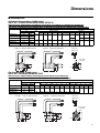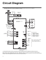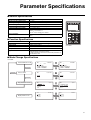
1
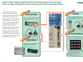
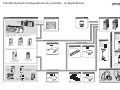
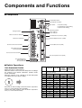
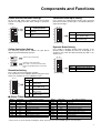
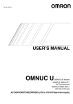
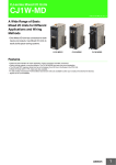
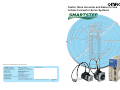
Faster, More Accurate and Easier to Use
A New Concept in Servo Systems
Note: Do not use this document to operate the Unit.
OMRON Corporation
Control Devices Division H.Q.
Shiokoji Horikawa, Shimogyo-ku,
Kyoto, 600-8530
Japan
Tel:(81)75-344-7109
Fax:(81)75-344-7149
OMRON ELECTRONICS LLC
1 East Commerce Drive, Schaumburg,
IL 60173 U.S.A.
Tel:(1)847-843-7900/Fax: (1)847-843-8568
Regional Headquarters
OMRON ASIA PACIFIC PTE. LTD.
83 Clemenceau Avenue,
#11-01, UE Square,
Singapore 239920
Tel:(65)6835-3011/Fax : (65)6835-2711
OMRON EUROPE B.V.
Wegalaan 67-69, NL-2132 JD Hoofddorp
The Netherlands
Tel:(31)2356-81-300/
Fax:(31)2356-81-388
OMRON (CHINA) CO., LTD.
Room 2211, Bank of China Tower,
200 Yin Cheng Zhong Road,
PuDong New Area, Shanghai, 200120 China
Tel:(86)21-5037-2222/Fax:(86)21-5037-2200
Authorized Distributor:
Note: Specifications subject to change without notice.
Cat. No. I807-E1-04
Printed in Japan
0405-1M
Quick, High-Torque, High-Precision Positionin g for Up to 15 Axes.
Plus, an Operating Environment that Ensures Fast and Easy Setup.
Backed by the trend toward
increasing complexity in motor
control, more advanced functions,
multifunctional versatility and
greater applications compatibility
Setup
Connection
Control cables for connecting drivers and
controllers are available for every type of controller
for easy connection. Motors are also connected
with a single cable. Special decelerators are also
available.
Basic setup requires no adjustments. Front-panel
switches make settings easy and eliminate the need
for time-consuming parameter settings whenever
adjustment is required. Ease of use is equivalent to
that of a stepping motor.
are demanded in servo systems.
This is further combined with the
need to raise productivity and
improve cost performance.
SMARTSTEP meets these needs
with high-speed, high-precision
positioning, fewer process steps,
speedier setup, and a variety of
Performance
functions that allow easy operation
and quick and efficient connection
Positioning is stable because SMARTSTEP prevents
out-of-step operation, making high-speed, hightorque, high-precision positioning easier than ever.
with peripheral components.
Speed vs. torque comparison for a 100-W motor
Operation
SMARTSTEP instantaneous peak torque
Torque (N.m)
1.0
0.8
OMRON PLCs and PTs combine to make monitoring
and debugging easier than ever. This functionality is
further enhanced by Programming Devices like
Monitoring Software and Parameter Units.
0.6
SMARTSTEP
rated torque
0.4
Stepping motor
torque
characteristics
NS 12
Programmable Terminal
0.2
SYSMAC CJ/CS-series PLC
0
1000
2000
3000
4000 Speed (r/min)
International standards
SMARTSTEP conforms to CE, UL, cUL and other
standards for international use.
2
3
Flexible System Configurations for a Variety of Applications
Controllers
Communications Cable
Parameter Unit
Monitoring and debugging possible
via SYSMAC C-series PLC.
R7A-PR02A
Connection to
NS5, NS8,
NS10, or NS12
SYSMAC
CJ Series
B.B
INP
VCMP
TGON
REF
AC Servo Drivers
POWER
R7A–PR02A PARAMETER UNIT
RESET
SCROLL
JOG
JO
READ
DRIVER
MODE/SET
DATA
R UN
UN
WRITE
PR
PR
DRIVER
NS12/10/8/5
*These models are shown as examples.
Power Cables
SYSMAC CS Series
Serial Communications Unit
Motor Cables
Special Servo Driver protocol
Communications Cable
XW2ZCS1W-SCB41-V1
CS1W-SCU21-V1
CJ1W-SCU41-V1
Pulse Train Command
J-C1
(See note.)
Servo Relay Unit
Servo Driver Cable
XW2B-40J6-4A
(with communications)
XW2Z-
J-B7
Integrated Motor
Power/Encoder
Cable
R7A-CEA
S
(without brake)
R7A-CEA
B
(with brake)
Position Control (NC) Units
Note: Refer to page 27 for details.
CS1W-NC113/213/413
NC133/233/433
C200HW-NC113/213/413
Motor power feedback signal
Serial Communications
Board
Separate Motor
Power and Encoder
Cables
R88A-CAW
S
(without brake)
R88A-CAW
S
(with brake)
Encoder Cable
Separate Motor
Power and Encoder
Cables
R7A-CRA
C
CJ1W-NC113/213/413
NC133/233/433
*With the Separate Motor
Power and Encoder
Cables, one Power Cable
and one Encoder Cable
is required.
AC Servomotor
SYSMAC
CJ1M
Customizable Counter Units
CS1W-HCP22-V1
Position Control Cable
Position Control Cable
Servo Relay Unit
Servo Driver Cable
XW2Z-
XW2B-
XW2Z-
J-A
J6- B (See note.)
J-B5 (See note.)
(See note.)
SYSMAC CPM2A
SYSMAC
CPM2C
One-axis
Positioner
3F88M-DRT141
*These models are shown as examples.
4
Note: Refer to page 27 for details.
5
Components and Functions
■ Components
Unit Number Switch
Gain Adjustment Switch
• Resolution Setting
• Command Pulse Input Setting
• Dynamic Brake Setting
DIP Switch
Autotuning Switch
Charge Indicator
Alarm Indicator
Power Indicator
Main-circuit Power Terminals
Communications Connector (CN3)
Monitor Output Connector (CN4)
DC Reactor Terminals
Control I/O Connector (CN1)
Control-circuit Power Terminals
External Regeneration
Resistor Terminals
Servomotor Power Terminals
Encoder Input Connector (CN2)
Ground Terminals for
Power Supply and
Servomotor Power
■ Switch Operations
Gain Adjustment Switch
Adjusts the motor’s responsiveness.
When this switch is set to 0, the Unit will operate according to
the settings in the internal parameters (Pn100, Pn101,
Pn102, and Pn401).
When this switch is set to 1 through F, the Unit will operate
according to the rotary switch’s setting.
F 0 1
2
Decrease the switch setting to lower the motor’s responsiveness (i.e., so that it moves more smoothly).
Increase the switch setting to raise the motor’s responsiveness (i.e., so that it moves faster).
6
Setting
0
Position
Loop Gain
Speed
Loop Gain
Speed
Loop
Integral
Constant
Torque
Command
Filter Time
Constant
Enables parameter settings (including settings other
than gain settings).
1
15
15
4,000
250
2
20
20
3,500
200
3
30
30
3,000
150
4
40
40
2,000
100
5
60
60
1,500
70
6
85
85
1,000
50
7
120
120
800
30
8
160
160
600
20
9
200
200
500
15
A
250
250
400
10
B
250
250
400
10
C
250
250
400
10
D
250
250
400
10
E
250
250
400
10
F
250
250
400
10
Components and Functions
Enable Switch/Parameter Settings
Command Pulse Input Setting
Pin 6 of the DIP switch selects whether the Servo Driver
operates according to the DIP switch settings or parameter
settings.
Pin 3 selects the command pulse mode. Select “Forward
pulse/Reverse pulse: positive logic” or “Feed pulses/Direction
signal: positive logic.”
Pin 6
ON OFF
6
5
4
3
2
1
DIP Switch/Parameter
Setting Selection
Enables the DIP switch
settings.
Enables the parameter settings.
OFF
ON
ON OFF
6
5
4
3
2
1
(Default setting)
Pin 3
OFF
ON
Command Pulse Mode
Forward pulse/Reverse
pulse: positive logic
Feed pulses/Direction signal: positive logic
(Default setting)
Dynamic Brake Setting
Online Autotuning Setting
The Autotuning Switch selects whether the gain will be
adjusted automatically during operation.
Pin 2 enables or disables dynamic brake operation. If the
dynamic brake is enabled, the motor can be brought to an
emergency stop when the RUN command goes OFF or an
alarm occurs.
ON OFF
Perform online autotuning.
1
ON OFF
Complete online autotuning.
The result is stored in the Inertia Ratio
parameter (Pn103) and the Servo Driver
runs.
1
Resolution Setting
Pins 4 and 5 select the positioning resolution.
If the resolution is set to 1,000 (the default setting), the motor
makes one revolution for every 1,000 pulses input.
Pins
ON OFF
6
5
4
3
2
1
(Default setting)
ON OFF
6
5
4
3
2
1
Pin 2
OFF
ON
Dynamic Brake Mode
Dynamic brake disabled.
Dynamic brake enabled.
(Default setting)
Resolution
5
4
OFF OFF 1,000 pulses/revolution
(0.36°/step)
OFF ON 10,000 pulses/revolution (0.036°/step)
ON OFF 500 pulses/revolution
(0.72°/step)
ON ON 5,000 pulses/revolution
(0.072°/step)
■ Alarm Table
Display
ALM output
Display
ALM output
A.04*
OFF
Parameter setting error
Error detection function
A.7A
OFF
Error detection function
A.10*
OFF
Overcurrent
A.bF*
OFF
System error
A.30
OFF
Regeneration error
A.C1
OFF
Runaway detected
A.32
OFF
Regeneration overload
A.C2*
OFF
Phase not detected
A.40
OFF
Overvoltage/Undervoltage
A.C3*
OFF
Encoder disconnect detected
A.51
OFF
Overspeed
A.d0
OFF
Deviation counter overflow
A.70
OFF
Overload
CPF00
---
Parameter Unit transmission error 1
A.73
OFF
Dynamic brake overload
CPF01
---
Parameter Unit transmission error 2
A.74
OFF
Inrush resistance overload
A.91
---
Overload warning
A.92
---
Regeneration overload warning
Overheat
* These errors are not cleared by resetting the alarm. The power must be turned ON again to clear the alarm.
7
Servo Driver Specifications
■ General Specifications
Item
Specification
Ambient operating temperature
0 to 55°C
Ambient operating humidity
90% max. (with no condensation)
Ambient storage temperature
−20 to 85°C
Ambient storage humidity
90% max. (with no condensation)
Storage/operating atmosphere
No corrosive gases.
Vibration resistance
10 to 55 Hz in X, Y, and Z directions with 0.1-mm double amplitude or acceleration of
4.9 m/s2 max., whichever is smaller
Impact resistance
Acceleration 19.6 m/s2 max., in X, Y, and Z directions, three times
Insulation resistance
Between power line terminals and case: 0.5 MΩ min. (at 500 V DC)
Dielectric strength
Between power line terminals and FG: 1,500 V AC for 1 min at 50/60 Hz
Between each control signal and FG: 500 V AC for 1 min
Protective structure
International
standards
Built into panel (IP10).
EC
Directives
EMC
Directive
EN55011 class A group 1
Low Voltage
Directive
EN50178
EN61000-6-2
UL Standards
UL508C
cUL Standards
cUL C22.2 No. 14
■ Performance Specifications
Control Specifications for 100-V AC Input Type
Item
Applicable Servomotor (R7M-)
100 V AC
30 W
50 W
100 W
200 W
400 W
R7D-APA3L
R7D-APA5L
R7D-AP01L
R7D-AP02L
R7D-AP04L
A03030
A05030
A10030
AP10030
A20030
AP20030
A40030
AP40030
Continuous output current (rms)
0.42
0.6
0.89
2.0
2.6
Momentary maximum output current (rms)
1.3
1.9
2.8
6.0
8.0
Control power supply
Single-phase 100/115 V AC (85 to 127 V) 50/60 Hz
Main-circuit power supply
Single-phase 100/115 V AC (85 to 127 V) 50/60 Hz (Voltage doubler method)
Control method
All-digital servo
Speed feedback
2,000 pulses/revolution Incremental Encoder
Inverter method
PWM method based on IGBT
PWM frequency
11.7 kHz
Weight
0.8
0.8
0.8
Compatible motor voltage
Compatible motor capacity
0.8
1.1
200 W
400 W
200 V
30 W
50 W
100 W
Command pulse response
250 kHz
Control Specifications for 200-V AC Input Type
Item
Applicable Servomotor (R7M-)
200 VAC
30 W
50 W
100 W
200 W
400 W
750 W
R7D-APA3H
R7D-APA5H
R7D-AP01H
R7D-AP02H
R7D-AP04H
R7D-AP08H
A03030
A05030
A10030
AP10030
A20030
AP20030
A40030
AP40030
A75030
AP75030
Continuous output current (rms)
0.42
0.6
0.89
2.0
2.6
4.4
Momentary maximum output current (rms)
1.3
1.9
2.8
6.0
8.0
13.9
Control power supply
Single-phase 200/230 V AC (170 to 253 V) 50/60 Hz
Main-circuit power supply
Single-phase 200/230 V AC (170 to 253 V) 50/60 Hz
(Three-phase 200/230 V AC can be used with the 750-W model.)
Control method
All-digital servo
Speed feedback
2,000 pulses/revolution Incremental Encoder
Inverter method
PWM method based on IGBT
PWM frequency
Weight
11.7 kHz
0.8
0.8
0.8
Compatible motor voltage
Compatible motor capacity
Command pulse response
8
0.8
1.1
1.7
200 W
400 W
750 W
200 V
30 W
50 W
100 W
250 kHz
Servo Driver Specifications
■ I/O Specifications
Terminal Specifications
Symbol
Name
L1 and L2
or
L1, L2, and L3
+1
Function
Main-circuit Power
Supply Terminals
These are the input terminals for the main-circuit power supply.
DC Reactor
Terminals
Normally short-circuit between +1 and +2.
If harmonic control measures are required, connect a DC Reactor between +1 and +2.
+2
−
Main-circuit DC Out- Do not connect anything to this terminal.
put
L1C
Control Circuit Power Supply Terminals
L2C
B1 and B2
or
B1, B2, and B3
U
V
These are the input terminals for the control power supply.
External Regenera- Connect an External Regeneration Resistor to these terminals if the regenerative capacity of the intertion Resistance Ter- nal capacitor is exceeded. (An External Regeneration Resistor cannot be connected to the 30 to 200minals
W models.)
Servomotor
Terminals
Red
Frame ground
This is the ground terminal.
W
These are the terminals for outputs to the Servomotor.
White
Blue
Control I/O (CN1) Specifications
Pin
Symbol
1
+PULS/CW/A
2
−PULS/CW/A
3
+SIGN/CCW/B
4
−SIGN/CCW/B
5
+ECRST
6
−ECRST
7
BKIR
8
INP
10
OGND
13
Name
Function/interface
Feed pulses, reverse pulses, or 90° phase Line-driver input: 7 mA at 3 V
difference pulses (A phase)
Open-collector input: 7 to 15 mA
Input impedance: 200 Ω
Direction signal, forward pulses, or 90°
Maximum response frequency: 250 kpps
phase difference pulses (B phase)
Position control is performed based on the pulses that have been input.
Deviation counter reset
Line-driver input: 7 mA at 3 V
Open-collector input: 7 to 15 mA
Input impedance: 200 Ω
ON: Resets deviation counter.
Brake interlock output
Outputs holding brake timing signals.
Positioning completed output
ON when the position error is within the positioning completed range.
Output ground common
Ground common for output signals (pins 7 and 8).
+24V
+24V DC power input for control
Power supply input (+24 V DC) for pins 14 and 18.
14
RUN
RUN command input
ON: Servo ON (Starts power to Servomotor.)
18
RESET
Alarm reset input
ON: Servo alarm status is reset.
19
GND
RS-422A ground
Ground for RS-422A
20
RXD+
RS-422A reception data
Interface for RS-422A data transfers
21
RXD−
22
TXD+
23
TXD−
24
RT
32
Z
33
ZCOM
34
ALM
35
ALMCOM
Shell
FG
RS-422A transmission data
Termination resistance terminal
Connect to RXD- (pin 21) in the Unit at the end of the line.
Encoder phase-Z open-collector output
Output goes ON when the encoder’s phase-Z signal (1 pulse/revolution) is detected.
Open-collector output: 20 mA max. at 30 V DC
Alarm output
Output goes OFF when alarm is detected.
Open-collector output: 50 mA max. at 30 V DC
Cable shield ground
Ground for cable's shield wire.
Compatible Connectors
Receptacle at Servo Driver: 10236-52A2JL (Sumitomo 3M) or equivalent
Cable solder plug: 10136-3000VE (Sumitomo 3M)
Cable case: 10336-52A0-008 (Sumitomo 3M)
9
Servo Driver Specifications
Encoder Connector (CN2) Specifications
Pin
1, 2, 3
4, 5, 6
8
9
10
11
12
13
Shell
Symbol
E0V
E5V
S+
S−
A+
A−
B+
B−
FG
Name
Encoder power supply GND
Encoder power supply +5 V
Encoder + phase-S input
Encoder − phase-S input
Encoder + phase-A input
Encoder − phase-A input
Encoder + phase-B input
Encoder − phase-B input
Cable shield ground
Function
Power supply outlet for encoder
Line driver input (conforms to EIA-RS422A)
(Input impedance: 220 Ω ± 5%)
Line driver input (conforms to EIA-RS422A)
(Input impedance: 220 Ω ± 5%)
Line driver input (conforms to EIA-RS422A)
(Input impedance: 220 Ω ± 5%)
Ground for cable's shield wire.
Compatible Connectors
Receptacle at Servo Driver: 10214-52AJL (Sumitomo 3M) or equivalent
Cable plug: 10114-3000VE (Sumitomo 3M)
Cable case: 10314-52A0-008 (Sumitomo 3M)
Communications Connector (CN3) Specifications
Pin
1
2
3
7
8
Shell
Symbol
/TXD
/RXD
PRMU
+5V
GND
FG
Name
Transmission data
Reception data
Unit switching
+5 V output
Ground
Cable shield ground
Function/
Transmission data: RS-232C output
Reception data: RS-232C input
Switching terminal for a Parameter Unit
This is the +5 V power supply output to the Parameter Unit.
Ground for cable's shield wire.
Compatible Connectors
Receptacle at Servo Driver: HR12-10R-8 SDL (Hirose Electric)
Cable connector: HR212-10P-8P (Hirose Electric)
Monitor Output (CN4) Specifications
Pin
1
2
3
4
Symbol
NM
AM
GND
GND
Name
Speed monitor
Current monitor
Ground
Ground
Compatible Connectors
Receptacle at Servo Driver: DF11-4DP-2DSA (01) (Hirose Electric)
Cable socket: DF11-4DS-2C (Hirose Electric)
Cable case: DF11-2428SCF (Hirose Electric)
10
Function/
Speed monitor output: 1 V per 1,000 r/min
Current monitor: 1 V / rated torque
Grounds for monitor output
Motor Specifications
■ General Specifications
Item
Specification
Ambient operating temperature
0 to 40°C
Ambient operating humidity
20% to 80% (with no condensation)
Ambient storage temperature
−20 to 60°C
Ambient storage humidity
20% to 80% (with no condensation)
Storage/operating atmosphere
No corrosive gases.
Vibration resistance
10 to 2,500 Hz in X, Y, and Z directions with 0.2-mm double amplitude or acceleration of 24.5 m/s2
max., whichever is smaller
Impact resistance
Acceleration 98 m/s2 max., in a vertical direction, two times
Insulation resistance
Between power line terminals and FG: 10 MΩ min. (at 500 V DC)
Dielectric strength
Between power line terminals and FG: 1,500 V AC for 1 min at 50/60 Hz
Run position
Any direction
Insulation grade
Type B
Structure
Totally-enclosed self-cooling
Protective structure
IP55 for both the Cylindrical and Flat Servomotors
Vibration grade
V-15
Mounting method
Flange-mounting
International standards
Approval obtained for UL, cUL, and EN (EMC directive and low-voltage directive)
■ Performance Specifications
Flat Servomotors
Item
Applicable Servo Driver (R7D-)
R7M-AP10030
R7M-AP20030
R7M-AP40030
R7M-AP75030
AP01H
AP01L
AP02H
AP02L
AP04H
AP04L
AP08H
Rated output
100 W
200 W
400 W
750 W
Rated torque
0.318 N⋅m
0.637 N⋅m
1.27 N⋅m
2.39 N⋅m
Rated rotation speed
3,000 r/min
3,000 r/min
3,000 r/min
3,000 r/min
Momentary maximum rotation speed
4,500 r/min
4,500 r/min
4,500 r/min
4,500 r/min
0.96 N⋅m
1.91 N⋅m
3.82 N⋅m
7.1 N⋅m
Rated current
0.89 A (rms)
2.0 A (rms)
2.6 A (rms)
4.1 A (rms)
Momentary maximum current
2.8 A (rms)
6.0 A (rms)
8.0 A (rms)
13.9 A (rms)
10-6
10-5
10-5
2.11 × 10⁻⁴ kg⋅m2
Momentary maximum torque
Rotor inertia
6.5 ×
Power rate
kg⋅m2
2.09 ×
kg⋅m2
3.47 ×
kg⋅m2
15.7 kW/s
19.4 kW/s
46.8 kW/s
Allowable radial load
78 N
245 N
245 N
392 N
Allowable thrust load
49 N
68 N
68 N
147 N
Without brake
0.7 kg
1.4 kg
2.1 kg
4.2 kg
With brake
0.9 kg
1.9 kg
2.6 kg
5.7 kg
Weight
Encoder resolution
2,000 pulses/revolution for phase-A and phase-B, 1 pulse/revolution for phase-Z
t6 × 250 mm square
Radiation shield dimensions
Brake Spec- Brake inertia
ifications
Excitation voltage
26.9 kW/s
t12 × 300 mm square
3.1 × 10⁻⁶ kg⋅m2
1.52 × 10⁻⁵ kg⋅m2
Power consumption (at
20°C)
7.5 W
7.6 W
8.2 W
7.5 W
Current consumption (at
20°C)
0.31 A
0.32 A
0.34 A
0.31 A
Static friction torque
0.4 N⋅m min.
0.9 N⋅m min.
1.9 N⋅m min.
3.5 N⋅m min.
Attraction time
60 ms max.
40 ms max.
60 ms max.
20 ms max.
Release time
20 ms max.
20 ms max.
20 ms max.
40 ms max.
1°
1°
1°
1°
Continuous
Continuous
Continuous
Continuous
Type F
Type F
Type F
Type F
Backlash
Rating
Insulation grade
1.52 × 10⁻⁵ kg⋅m2
8.75 × 10⁻⁵ kg⋅m2
24 V DC ±10%
11
Motor Specifications
■ Torque and Rotation Speed Characteristics
Flat Servomotors
The following graphs show the characteristics with a 3-m standard cable and an R7D-AP@L Servo Driver (100-V AC input) or
R7D-AP@H Servo Driver (200-V AC input).
R7M-AP10030 (100 W)
R7M-AP20030 (200 W)
(N•m)
1.0
(N•m)
0.96
2.0
0.96
(3725)
0.8
0.8
Repeated usage
1.5
Repeated usage
1.91
(3600)
1.91
1.4
0.6
1.0
0.4
0.318
0.2
0.637
0.318
0.5
0.222
Continuous usage
1000
2000
3000
4000
5000
(r/min)
0
R7M-AP40030 (400 W)
1000
2000
3000
4000
5000
R7M-AP75030 (750 W)
(N•m)
4.0
0.452
Continuous usage
(r/min)
0
0.637
(N•m)
3.82
(2350)
8.0
3.82
(3250)
(2500)
7.1
7.1
(3200)
100 VAC input
3.0
Single-phase
200 VAC input
6.0
Repeated usage
3-phase
200 VAC input
Repeated usage
2.0
4.0
1.77
1.27
1.27
12
2000
3000
2.45
1.64
1.54
Continuous usage
(r/min)
1000
2.39
2.0
0.89
Continuous usage
0
2.39
1.22
1.0
4000
5000
0
(r/min)
1000
2000
3000
4000
5000
Motor Specifications
■ Performance Specifications
Cylindrical Servomotors
Item
R7M-A03030 R7M-A05030 R7M-A10030 R7M-A20030 R7M-A40030 R7M-A75030
Applicable Servo Driver (R7D-)
APA3H
APA5H
AP01H
AP02H
AP04H
AP08H
APA3L
APA5L
AP01L
AP02L
AP04L
Rated output
30 W
50 W
100 W
200 W
400 W
750 W
Rated torque
0.095 N⋅m
0.159 N⋅m
0.318 N⋅m
0.637 N⋅m
1.27 N⋅m
2.39 N⋅m
Rated rotation speed
3,000 r/min
3,000 r/min
3,000 r/min
3,000 r/min
3,000 r/min
3,000 r/min
Momentary maximum rotation 4,500 r/min
4,500 r/min
4,500 r/min
4,500 r/min
4,500 r/min
4,500 r/min
speed
Momentary maximum torque
0.29 N⋅m
0.48 N⋅m
0.96 N⋅m
1.91 N⋅m
3.82 N⋅m
7.1 N⋅m
Rated current
0.42 A (rms) 0.6 A (rms) 0.87 A (rms) 2.0 A (rms)
2.6 A (rms)
4.4 A (rms)
Momentary maximum current
1.3 A (rms)
1.9 A (rms)
2.8 A (rms)
6.0 A (rms)
8.0 A (rms) 13.9 A (rms)
Rotor inertia
1.7 × 10⁻⁶
2.2 × 10⁻⁶
3.6 × 10⁻⁶
1.19 × 10⁻⁵
1.87 × 10⁻⁵
6.67 × 10⁻⁵
kg⋅m2
kg⋅m2
kg⋅m2
kg⋅m2
kg⋅m2
kg⋅m2
Power rate
Allowable radial load
Allowable thrust load
Weight Without brake
With brake
Encoder resolution
Radiation shield dimensions
5.31 kW/s
11.5 kW/s
28.1 kW/s
34.1 kW/s
86.3 kW/s
85.6 kW/s
68 N
68 N
78 N
245 N
245 N
392 N
54 N
54 N
54 N
74 N
74 N
147 N
0.3 kg
0.4 kg
0.5 kg
1.1 kg
1.7 kg
3.4 kg
0.6 kg
0.7 kg
0.8 kg
1.6 kg
2.2 kg
4.3 kg
2,000 pulses/revolution for phase-A and phase-B, 1 pulse/revolution for phase-Z
Brake
Specifications
0.85 × 10⁻⁶
kg⋅m2
Brake inertia
t6 × 250 mm square
0.85 × 10⁻⁶
kg⋅m2
Excitation voltage
Power consumption
6W
6W
(at 20°C)
Current consump0.25 A
0.25 A
tion (at 20°C)
Static friction torque 0.2 N⋅m min. 0.2 N⋅m min.
Attraction time
Release time
Backlash
Rating
Insulation grade
30 ms max.
60 ms max.
1°
Continuous
Type F
30 ms max.
60 ms max.
1°
Continuous
Type F
0.85 × 10⁻⁶
kg⋅m2
6.4 × 10⁻⁶
kg⋅m2
24 V DC ±10% V
6W
7W
6.4 × 10⁻⁶
kg⋅m2
1.7 × 10⁻⁵
7W
7.7 W
kg⋅m2
0.25 A
0.29 A
0.29 A
0.32 A
0.34 N⋅m
min.
30 ms max.
60 ms max.
1°
Continuous
Type F
1.47 N⋅m
min.
60 ms max.
20 ms max.
1°
Continuous
Type F
1.47 N⋅m
min.
60 ms max.
20 ms max.
1°
Continuous
Type F
2.45 N⋅m
min.
60 ms max.
20 ms max.
1°
Continuous
Type F
13
Motor Specifications
■ Torque and Rotation Speed Characteristics
Cylindrical Servomotors
The following graphs show the characteristics with a 3-m standard cable and an R7D-AP@L Servo Driver (100-V AC input.) or
R7D-AP@H Servo Driver (200-V AC input.)
R7M-A03030 (30 W)
R7M-A05030 (50 W)
(N•m)
0.3
(N•m)
0.29
0.5
0.29
0.48
0.48
0.4
0.2
Repeated usage
Repeated usage
0.3
0.2
0.1
0.095
0.159
0.095
0.069
0.1
Continuous usage
(r/min)
0
1000
2000
3000
4000
5000
R7M-A10030 (100 W)
0.107
Continuous usage
(r/min)
0
1000
2000
3000
4000
5000
R7M-A20030 (200 W)
(N•m)
(N•m)
1.0
0.159
2.0
0.96
0.96
(3600)
1.91
1.91
(3650)
0.91
0.8
1.5
1.33
Repeated usage
Repeated usage
0.6
1.0
0.4
0.318
0.2
0.637
0.318
0.5
0.222
Continuous usage
1000
2000
3000
4000
5000
R7M-A40030 (400 W)
(r/min)
0
1000
3000
4000
5000
(N•m)
(2000)
3.82
8.0
3.82
(2900)
7.1
(2225)
7.1
100 VAC input
3.0
6.0
Repeated usage
Repeated usage
2.0
4.0
1.27
1.0
2000
R7M-A75030 (750 W)
(N•m)
4.0
0.452
Continuous usage
(r/min)
0
0.637
1.45
1.27
2.39
1.24
0.89
Continuous usage
2.0
2.39
Continuous usage
1.24
0
14
(r/min)
1000
2000
3000
4000
5000
0
(r/min)
1000
2000
3000
4000
5000
Decelerator Specifications
■ Performance Specifications
Backlash within 45 Minutes
Motor
capacity
Deceleration ratio
Model (R7G-)
For Cylindrical
Servomotors
50 W
100 W
200 W
400 W
750 W
Note:
For Flat
Servomotors
Rated
rotation
speed
Rated
torque
Efficiency
Instantaneous
peak rotation
speed
Instantaneous peak
torque
Decelerator
inertia
(See note 1.)
Allowable
radial load
(shaft center)
(See note 4.)
Allowable
thrust load
r/min
N·m
%
r/min
N·m
kg·m2
N
N
1/5
RGSF05B50
---
600
0.517
65
900
1.56
4.13 × 10⁻⁶
392
196
1/9
RGSF09B50
---
333
0.93
65
500
2.81
3.53 × 10⁻⁶
441
220
1/15
RGSF15B50
---
200
1.67
70
300
5.04
3.67 × 10⁻⁶
588
294
1/25
RGSF25B50
---
120
2.78
70
180
8.40
3.59 × 10⁻⁶
686
343
1/5
RGSF05B100
RGSF05B100P
600
1.19
75
900
3.60
4.08 × 10⁻⁶
392
196
1/9
RGSF09B100
RGSF09B100P
333
2.29
80
500
6.91
3.43 × 10⁻⁶
441
220
1/15
RGSF15B100
RGSF15B100P
200
3.82
80
300
11.5
3.62 × 10⁻⁶
588
294
1/25
RGSF25B100
RGSF25B100P
120
4.02
(See note 2.)
50
180
12.0
(See note 2.)
3.54 × 10⁻⁶
686
343
1/5
RGSF05B200
RGSF05B200P
600
2.71
85
900
8.12
1.53 × 10⁻⁵
392
196
1/9
RGSF09C400
RGSF09C400P
333
3.78
66
500
11.3
2.68 × 10⁻⁵
931
465
1/15
RGSF15C400
RGSF15C400P
200
6.31
66
300
18.9
2.71 × 10⁻⁵
1176
588
1/25
RGSF25C400
RGSF25C400P
120
11.1
70
180
33.4
2.67 × 10⁻⁵
1323
661
1/5
RGSF05C400
RGSF05C400P
600
5.4
85
900
16.2
3.22 × 10⁻⁵
784
392
1/9
RGSF09C400
RGSF09C400P
333
9.49
83
500
28.5
2.68 × 10⁻⁵
931
465
1/15
RGSF15C400
RGSF15C400P
200
15.8
83
300
47.6
2.71 × 10⁻⁵
1176
588
1/25
RGSF25C400
RGSF25C400P
120
21.7
(See note 2.)
68
180
65.1
(See note 2.)
2.67 × 10⁻⁵
1323
661
10−5
1/5
RGSF05C750
RGSF05C750P
600
10.8
90
900
32.0
7.17 ×
784
392
1/9
RGSF09C750
RGSF09C750P
333
9.7
(See note 2.)
45
500
29.1
(See note 2.)
6.23 × 10⁻⁵
931
465
1/15
RGSF15C750
RGSF15C750P
200
16.2
(See note 2.)
45
300
48.6
(See note 2.)
6.56 × 10⁻⁵
1176
588
1/25
RGSF25C750
RGSF25C750P
120
21.7
(See note 2.)
36
180
65.1
(See note 2.)
6.5 × 10⁻⁵
1323
661
1.
2.
3.
4.
This inertia is for Cylindrical Servomotors. Refer to the Flat Servomotor User's Manual (Cat. No. I533) for applicable inertia for that model.
This torque is for the decelerator. Be sure to select a motor capacity with torque no higher than this value.
This decelerator is for a Servomotor with a straight shaft without a key.
The value given for the allowable radial load is the value at the center of the shaft.
Backlash within 3 Minutes
Motor
capacity
Deceleration ratio
Model (R7G-)
For Cylindrical
Servomotors
50 W
100 W
200 W
400 W
750 W
Note:
For Flat
Servomotors
Rated
rotation
speed
Rated
torque
Efficiency
Instantaneous
peak rotation
speed
Instantaneous peak
torque
Decelerator
inertia
(See note 1.)
r/min
N·m
%
r/min
N·m
kg·m2
Allowable
radial load
(shaft center)
(See note 3.)
Allowable
thrust load
N
N
1/5
VRSFPB05B50
---
600
0.517
65
900
1.56
−6
4.13 × 10
392
196
1/9
VRSFPB09B50
---
333
0.93
65
500
2.81
3.53 × 10⁻⁶
441
220
1/15
VRSFPB15B50
---
200
1.67
70
300
5.04
3.67 × 10⁻⁶
588
294
1/25
VRSFPB25B50
---
120
2.78
70
180
8.40
3.59 × 10⁻⁶
686
343
1/5
VRSFPB05B100
VRSFPB05B100P
600
1.19
75
900
3.60
4.08 × 10⁻⁶
392
196
1/9
VRSFPB09B100
VRSFPB09B100P
333
2.29
80
500
6.91
3.43 × 10⁻⁶
441
220
1/15
VRSFPB15B100
VRSFPB15B100P
200
3.82
80
300
11.5
3.62 × 10⁻⁶
588
294
1/25
VRSFPB25C100
VRSFPB25C100P 120
6.36
80
180
19.2
3.92 × 10⁻⁶
1323
661
1/5
VRSFPB05B200
VRSFPB05B200P
600
2.71
85
900
8.12
1.53 × 10⁻⁵
392
196
1/9
VRSFPB09C400
VRSFPB09C400P 333
3.78
66
500
11.3
2.68 × 10⁻⁵
931
465
1/15
VRSFPB15C400
VRSFPB15C400P 200
6.31
66
300
18.9
2.71 × 10⁻⁵
1176
588
1/25
VRSFPB25C200
VRSFPB25C200P 120
11.1
70
180
33.4
2.67 × 10⁻⁵
1323
661
1/5
VRSFPB05C400
VRSFPB05C400P 600
5.40
85
900
16.2
3.22 × 10⁻⁵
784
392
1/9
VRSFPB09C400
VRSFPB09C400P 333
9.49
83
500
28.5
2.68 × 10⁻⁵
931
465
1/15
VRSFPB15C400
VRSFPB15C400P 200
15.8
83
300
47.6
2.71 × 10⁻⁵
1176
588
1/25
VRSFPB25D400
VRSFPB25D400P 120
26.4
83
180
79.3
2.79 × 10⁻⁵
1617
808
1/5
VRSFPB05C750
VRSFPB05C750P 600
10.8
90
900
32.0
7.17 × 10⁻⁵
784
392
1/9
VRSFPB09D750
VRSFPB09C750P 333
18.3
85
500
54.3
6.50 × 10⁻⁵
1176
588
1/15
VRSFPB15D750
VRSFPB15D750P 200
30.5
85
300
90.5
7.09 × 10⁻⁵
1372
686
1/25
VRSFPB25E750
VRSFPB25E750P
50.8
85
180
151
7.05 × 10⁻⁵
2058
1029
120
1. This inertia is for Cylindrical Servomotors. Refer to the Flat Servomotor User's Manual (Cat. No. I533) for applicable inertia for that model.
2. This decelerator is for a Servomotor with a straight shaft without a key.
3. The value given for the allowable radial load is the value at the center of the shaft.
15
Dimensions
■ Servo Drivers
200 V AC: 30 W/50 W/100 W/200 W
Mounting dimensions
(R7D-APA3H/APA5H/AP01H/AP02H)
100 V AC: 30 W/50 W/100 W/200 W
5.5
Two, M4
(R7D-APA3L/APA5L/AP01L/AP02L)
160
160
149.5±0.5
(5)
(75)
55
130
5
55
17
200 V AC: 400 W
(R7D-AP04H)
Mounting dimensions
5 dia. hole
100 V AC: 400 W
5.5
Two, M4
5.5
(R7D-AP04L)
160
160
149.5±0.5
149.5
5
(5)
12
12
75
(5)
(75)
(63)
75
130
17
200 V AC: 750 W
(R7D-AP08H)
Mounting dimensions
5 dia. hole
5.5
Two, M4
94
160
160
149.5±0.5
35
96
55
90
(5)
180
(75)
17
16
27
90
Dimensions
■ Servomotors
Cylindrical Servomotors (3,000 r/min)
200 V AC: 30 W/50 W/100 W/200 W/400 W/750 W
Without Brake: R7M-A03030(-S1)/A05030(-S1)/A10030(-S1)/A20030(-S1)/A40030(-S1)/A75030(-S1)
With Brake: R7M-A03030-B(S1)/A05030-B(S1)/A10030-B(S1)/A20030-B(S1)/A40030-B(S1)/A75030-B(S1)
Dimensions (mm)
Model
LL
LR
Without B
With B
69.5
101
R7M-A05030@
77
108.5
R7M-A10030@
94.5
135
R7M-A03030@
R7M-A20030@
96.5
136
R7M-A40030@
124.5
164
R7M-A75030@
145
189.5
Axis end
Flange surface
D2
F
G
C
D1
25
40
46
30h7
30
60
70
h7
50
3
6
40
80
90
70h7
3
8
5
2.5
Z
S
QK*
b*
h*
t1*
Two, 4.3 dia.
6h6
14
2
2
1.2
3
3
1.8
5
5
3
8h6
Four, 5.5 dia.
14h6
20
Four, 7 dia.
16h6
30
* Dimensions of R7M-A@-@S1(with key)
R7M-A@@@30(-S1) (Without Brake)
R7M-A@@@30-B(-S1) (With Brake)
300
*Axis end
dimensions
300
b
t1
h
300
300
Hole with
“Z” mark
QK*
QK*
C
S dia. D2 dia.
S dia. D2 dia.
D1 dia.
G
LL
G
F
LR
C
F
LR
LL
Flat Servomotors (3,000 r/min)
200 V AC: 100 W/200 W/400 W/750 W
Without Brake: R7M-AP10030(-S1)/AP20030(-S1)/AP40030(-S1)/AP75030(-S1)
With Brake: R7M-AP10030-B(S1)/AP20030-B(S1)/AP40030-B(S1)/AP75030-B(S1)
Dimensions (mm)
Model
LL
LR
Without B
With B
R7M-AP10030@
62
91
R7M-AP20030@
67
98.5
R7M-AP40030@
87
118.5
R7M-AP75030@
86.5
120
Flange surface
Axis end
C
D1
D2
F
G
Z
S
QK*
b*
h*
t1*
25
60
70
50h7
3
6
5.5
8h6
14
3
3
1.8
30
80
90
70h7
3
8
7
14h6
16
5
5
3
40
120
145
110h7
3.5
10
10
16h6
22
* Dimensions of R7M-A@-@S1(with key)
R7M-AP@@@30(-S1) (Without Brake)
*Axis end
dimensions
R7M-AP@@@30-B(-S1) (With Brake)
300
300
b
t1
h
300
300
Four, Z-dia.
mounting
holes
QK*
QK*
S dia. D2 dia.
S dia. D2 dia.
C
D1 dia.
G
LL
F
LR
G
LL
F
LR
C
17
Circuit Diagram
Single-phase 200 to 230 V AC +10%/–15% (50/60 Hz) or Single-phase 100 to 115 V AC +10%/–15% (50/60 Hz)
(The 750-W Servo Drivers can input three-phase 200 to 230 V AC.)
1MCCB
Noise filter
Main-circuit
power supply
OFF
Main-circuit
contactor
ON
1MC
1MC
X
Surge
suppressor
∗
B1
B2
Servomotor
1MC
U
L1
V
L2
SMARTSTEP A-series
Servo Driver
M
W
L1C
L2C
If necessary, connect a
DC Reactor to these
terminals to suppress
high harmonics in the
power supply.
+
1
+
2
RE
CN2
−
Always ground
this terminal.
Attach the shield wire to
the terminal securely.
CN1
Reverse
Pulses
+CW 1
−CW 2
200 Ω
Forward
Pulses
+CCW 3
−CCW 4
200 Ω
Deviation
Counter
Reset
+ECRST 5
−ECRST 6
200 Ω
Position
Commands
Encoder
22
23
TXD+ Transmission
TXD− data
20
21
RXD+ Reception
RXD− data
220 Ω
24
8
+24VIN 13
24 V DC
RUN
Command
Alarm reset
7
10
RUN 14
3.3k
32
RESET 18
33
3.3k
34
35
RT
Terminating
Resistor
INP
Positioning
Completed
Output
Brake
BKIR Interlock
Output
OGND
Z
RS-422 Interface
Compatible Line Drivers
Texas Inst. SN75174,
MC3487 or equivalent
Compatible Line Receivers
Texas Inst. SN75175,
MC3486 or equivalent
Max. operating voltage: 30 V DC
Max. output current: 50 mA
(Phase-Z output is 20 mA max.)
Phase Z
ZCOM
ALM
Alarm
Output
ALMCOM
Shell
FG (Frame Ground)
Connect the shield wire to the
connector shell.
∗ A Regeneration Resistor can be connected across the B1 and B2 terminals with 400-W and 750-W Servo Drivers.
When using an external Regeneration Resistor with a 400-W Servo Driver, just connect it across the B1 and B2 terminals.
When using an external Regeneration Resistor with a 750-W Servo Driver, remove the jumper bar from the B2 and B3 terminals
and then connect the Regeneration Resistor across the B1 and B2 terminals.
18
Parameter Specifications
■ General Specifications
Item
Specification
Ambient operating temperature
0 to 55°C
Ambient operating humidity
90% max. (with no condensation)
Ambient storage temperature
−20 to 85°C
Ambient storage humidity
90% max. (with no condensation)
Storage/operating atmosphere
No corrosive gases.
Vibration resistance
10 to 55 Hz in X, Y, and Z directions with 0.1-mm double amplitude or acceleration of
9.8 m/s2 max., whichever is smaller
Impact resistance
B.B
INP
VCMP
TGON
REF
POWER
R7A–PR02A PARAMETER UNIT
Acceleration 19.6 m/s2 max., in X, Y, and Z directions, three
times
SCROLL
RESET
JOG
MODE/SET
DATA
RUN
■ Function Specifications
Item
READ
Function
DRIVER
Setting mode
Display or change parameter settings.
Monitor mode
Display monitor values.
Execute Function mode
Execute each function mode.
Display Alarms
Display alarms that have occurred.
Copy Parameters
Read or save parameters from the Servo Driver.
Write parameters to the Servo Driver.
Compare parameters in the Servo Driver with parameters in
the Parameter Unit.
WRITE
PR
PR
DRIVER
R7A-PR02A
■ Mode Change Specifications
Power ON
Parameter/Monitor mode
MODE/SET
MODE/SET
Function mode
MODE/SET
Copy Parameters mode
Display Alarms mode
-PRM/MONBB
Un000 = 3000 r/min
Un002 = 40%
Un008 = 00100pulse
Un00D = 10000000
BB
Fn000
Fn001
Fn002
Fn003
BB
1
→PR
2: PR→DRIVER
3: Verify
4: LIST
A. 70
1: A.00
2: A.02
3: A.10
4: A.71
-FUNCTION-
-COPY-
-ALARM-
-PRM/MONBB
Pn000 = 0000
Un002 = 40%
Un008 = 00100pulse
Un00D = 10000000
BB
Fn001
Fn002
Fn003
Fn005
BB
1: DRIVER→PR
2: PR→DRIVER
3: Verify
4: LIST
A. 70
2: A.02
3: A.10
4: A.71
5: A.72
-FUNCTION-
-COPY-
-ALARM-
19
Parameter Specifications
■ Parameter Details
Parameter
number
Parameter name
Digit
Pn000
Function selection basic switch 1
(See note 1.)
0
1
2 to 3
Pn001
Function selection basic switch 2
(See note 1.)
0
1 to 3
Reverse rotation
Setting
Explanation
Default
setting
Unit
Setting
range
0
CCW direction is taken for positive command
0010
---
---
1
CW direction is taken for positive command
1002
---
---
80
Hz
1 to
2,000
2000
0.01 ms
15 to
51,200
Control mode
1
Position control by pulse train command
Not used.
---
---
Select stop method if an alarm occurs when
Servomotor is
OFF
0
Servomotor stopped by dynamic brake.
1
Stop by dynamic brake and release
brake after Servomotor stops.
2
Servomotor stopped with free run
Not used.
---
---
Pn100
Speed loop gain
Adjusts speed loop’s responsiveness.
Pn101
Speed loop integral
constant
Speed loop integral time constant
Pn102
Position loop gain
Adjusts position loop’s responsiveness.
40
1/s
1 to
2,000
Pn103
Inertia ratio
Set using the ratio between the machine system inertia and the Servomotor rotor inertia.
300
%
0 to
10,000
Pn109
Feed-forward amount
Position control feed-forward compensation value
0
%
0 to 100
Pn10A
Feed-forward command filter
Sets position control feed-forward command filter.
0
0.01 ms
0 to
6,400
Pn110
Online autotuning setting
(See note 1.)
0012
---
---
0
Selects online
auto-tuning
0
Auto-tunes initial operations only after
power is turned ON.
1
Always auto-tunes.
2
No auto-tuning
1
Not used.
---
---
2
Selects adhesive
friction compensation function
0
Friction compensation: OFF
1
Friction compensation: rated torque ratio
small
2
Friction compensation: rated torque ratio
large
---
---
3
20
Name
Not used.
Parameter Specifications
Parameter
number
Pn200
Parameter name
Position control setting 1
(See note 1.)
Digit
0
1
2
3
Pn202
Electronic gear ratio
G1 (numerator)
(See note 1.)
Pn203
Electronic gear ratio
G2 (denominator)
(See note 1.)
Pn204
Position command filter time constant 1
(primary filter)
Pn207
Position control setting 2
(See note 1.)
Name
Command pulse
mode
Deviation counter
reset
Deviation counter
reset if an alarm
occurs when the
Servomotor is
OFF
Not used.
Setting
Explanation
0
Feed pulses/Direction signal: Positive
logic
1
Forward pulse/Reverse pulse: Positive
logic
2
90° phase difference (A/B phase) signal
(x1): Positive logic
3
90° phase difference (A/B phase) signal
(x2): Positive logic
4
90° phase difference (A/B phase) signal
(x4): Positive logic
5
Feed pulses/Direction signal: Negative
logic
6
Forward pulse/Reverse pulse: Negative
logic
7
90° phase difference (A/B phase) signal
(x1): Negative logic
8
90° phase difference (A/B phase) signal
(x2): Negative logic
9
90° phase difference (A/B phase) signal
(x4): Negative logic
0
High level signal
1
Rising signal (low to high)
2
Low level signal
3
Falling signal (high to low)
0
Deviation counter reset if an alarm occurs when Servomotor is OFF.
1
Deviation counter not reset if an alarm
occurs when Servomotor is OFF.
2
Deviation counter reset only if alarm occurs.
---
---
Sets the pulse rate for the command pulses and Servo Servomotor travel distance.
Setting range: 0.01 ≤ G1/G2 ≤ 100
Sets soft start for command pulse. (Soft start characteristics are for the primary
filter.)
0
1 to 3
Selects position
command filter.
0
Primary filter
1
Linear acceleration and deceleration
Not used.
---
---
Default
setting
Unit
Setting
range
1011
---
---
4
---
1 to
65,535
1
---
1 to
65,535
0
0.01 ms
0 to
6,400
0000
---
---
0
0.01 ms
0 to
6,400
Pn208
Position command filter time constant 2
(linear acceleration
and deceleration)
(See note 1.)
Sets soft start for command pulse. (soft start characteristics are for the linear
acceleration and deceleration.)
Pn304
Jog speed
Sets rotation speed during jog operation.
500
r/min
0 to
10,000
Pn401
Torque command filter time constant
Sets the constant when filtering the internal torque command.
40
0.01 ms
0 to
65,535
Pn402
Forward torque limit
Forward rotation output torque limit (percentage of rated torque ratio).
350
%
0 to 800
Pn403
Reverse torque limit
Reverse rotation output torque limit (percentage of rated torque ratio).
350
%
0 to 800
Pn500
Positioning completion range
Sets the range of positioning completed output signal
3
Command
units
0 to 250
Pn505
Deviation counter
overflow level
Sets the detection level for the deviation counter over alarm.
1024
×256 command units
1 to
32767
Pn600
Regeneration resistor
capacity
(See note 2).
Setting for regeneration resistance load ratio monitoring calculations.
0
10 W
See
model
specs.
Note: 1. These parameters are read when the power is turned ON. Parameter Pn110.2 is valid when online.
2. When using a Regeneration Resistor, set the resistor’s capacity when the temperature has risen to 120°C. Set this parameter to 0 if a Regeneration Resistor is not being used.
21
Parameter Specifications
■ Function Mode Details
Number
Name
Explanation
Fn000
Alarm history display
Displays up to 10 alarm entries.
Fn001
Rigidity setting during online auto- Sets the control target during online auto-tuning.
tuning
Fn002
Jog operation
Makes the Servomotor rotate using key operations from the Parameter Unit.
Fn003
Servomotor origin search
Makes the Servomotor rotate using key operations from the Parameter Unit and fixes the position of phase Z after phase Z is detected.
Fn005
User parameter initialization
Restores user parameters to their default settings.
Fn006
Alarm history data clear
Clears the data stored in the alarm history.
Fn007
Store online auto-tuning results
Writes the load data calculated using online auto-tuning to Pn103 (inertia ratio).
Fn00C
Analog monitor output offset man- Manually adjusts the analog output monitor offset.
ual adjustment
Fn00D
Analog monitor output scaling
Fn00E
Servomotor current detection off- Automatically adjusts the offset for Servomotor current detection.
set automatic adjustment
Fn00F
Servomotor current detection off- Manually adjusts the offset for Servomotor current detection.
set manual adjustment
Fn010
Password setting
You can permit or prohibit writing to user parameters.
Fn012
Version check
Check the Servo Driver’s version information.
Changes the analog monitor output scaling (output voltage adjustment).
■ Monitor Mode Details
Number
22
Contents
Un000
Speed feedback
Un002
Torque command
Un003
Number of pulses from phase-Z edge
Un004
Electrical angle
Un005
Input signal monitor
Un006
Output signal monitor
Un007
Command pulse speed display
Un008
Position deviation (deviation counter)
Units
r/min
%
Pulses
°
----r/min
Command
units
Explanation
Displays actual rotation speed of Servomotor.
Displays command values to current loop (rated torque = 100%).
Displays rotation position from phase-Z edge (4X calculation).
Displays the electrical angle of the Servomotor.
Displays the control input signal (CN1) status using ON/OFF bits.
Displays the control output signal (CN1) status using ON/OFF bits.
Calculates and displays command pulse frequency in r/min.
Displays number of residual pulses in deviation counter (input pulse
standard).
Un009
Cumulative load ratio
%
Displays effective torque (rated torque = 100%, 10-s cycle)
Un00A
Regeneration load ratio
%
Displays regeneration absorption power due to regeneration resistance
(calculates internal resistance capacity or Pn600 setting as 100% in
10-s cycles).
Un00B
Dynamic brake resistance load ratio
%
Displays power consumption during dynamic brake operation (calculates tolerance power consumption as 100% in 10-s cycles).
Un00C
Input pulse counter
Un00D
Feedback pulse counter
Command
units
Pulses
Counts and displays input pulses (displayed in hexadecimal).
Counts and displays feedback pulses (4X calculation, displayed in hexadecimal).
Model Number Legends
AC Servomotors
AC Servo Drivers
R7M-A@@@@@@-@@@
1
No.
1
2
3
4
5
6
7
2 3
4
5
6
R7M-AP@@@
7
Item
Code
Indicates a Servomotor
Series
A
Type
Blank
P
Motor capacity 030
050
100
200
400
750
Speed
30
Brake
Blank
B
Shaft
Blank
S1
Specification
--Cylinder motor
Flat motor
30 W
50 W
100 W
200 W
400 W
750 W
3000 r/min
No brake
24-V DC brake
Straight shaft without key
Straight shaft with key
1
2
3
4
1
2
No.
Item
Code
Indicates a Servo Driver
Series
AP
Maximum out- A3
put capacity
A5
01
02
04
08
Power supply
H
specification
L
3
4
Specification
--30 W
50 W
100 W
200 W
400 W
750 W
200 VAC
100 VAC
23
Connecting Cables
SMARTSTEP
Servo Driver
Analog Monitor
Computer Monitor
Software for Windows
Position Control
Unit,
Customizable
Counter Unit, or
DeviceNet oneaxis positioner
Servo Relay Unit
SMARTSTEP
Servomotor
Serial Communications Unit/Board
Connector Terminal
Block
Position Control Unit
(with pulse output)
■ Integrated Motor Cables (For CN2)
Symbol
Name
Compatible
Servomotors
Servomotor Cable R7M-A@@@30
(for Servomotor
R7M-A@@@30-S1
without brake)
R7M-AP@@@30
R7M-AP@@@30-S1
Model
R7A-CEA@@@S
The boxes in the
model number are
for the cable
length: 1 m, 3 m,
5 m, 10 m, 15 m,
or 20 m.
Description
Power Cable
Servomotor connector
(Taiko Electronics Amp)
Connector Cap: 350780-1
Connector Socket: 350570-3
Encoder Cable
Motor Connector (Molex)
Connector: 54280-0800
Servomotor Cable R7M-A@@@30-B
(for Servomotor
R7M-A@@@30-BS1
with brake)
R7M-AP@@@30-B
R7M-AP@@@30-BS1
R7A-CEA@@@B
The boxes in the
model number are
for the cable
length: 1 m, 3 m,
5 m, 10 m, 15 m,
or 20 m.
Power Cable
Servomotor connector
(Taiko Electronics Amp)
Connector Cap: 350781-1
Connector Socket: 350570-3
Encoder Cable
Motor Connector (Molex)
Connector: 54280-0800
24
Driver Connector (Sumitomo 3M)
Connector Plug: 10114-3000VE
Connector Case: 10314-52A0-008
Driver Connector (Sumitomo 3M)
Connector Plug: 10114-3000VE
Connector Case: 10314-52A0-008
Connecting Cables
■ Separate Motor Cables (For CN2)
Symbol
Name
Power Cable (for
Motor without
brake)
Compatible
Servomotors
R7M-A@@@30
R7M-A@@@30-S1
R7M-AP@@@30
R7M-AP@@@30-S1
Model
R88A-CAWA@@@S
The boxes in the
model number are
for the cable
length: 3 m, 5 m,
10 m, 15 m, or 20
m.
Power Cable (for R7M-A@@@30-B
R88A-CAMotor with brake) R7M-A@@@30-BS1 WA@@@B
R7M-AP@@@30-B
The boxes in the
R7M-AP@@@30-BS1 model number are
for the cable
length: 3 m, 5 m,
10 m, 15 m, or 20
m.
Encoder Cable
R7M-A@@@30@
R88AR7M-AP@@@30@
CRA@@@C
The boxes in the
model number are
for the cable
length: 3 m, 5 m,
10 m, 15 m, or 20
m.
Note: A
Power Cable and an
Description
Motor Connector (Tyco Electronics Amp)
Connector Cap: 350780-1
Connector Socket: 350570-3
Motor Connector (Tyco Electronics Amp)
Connector Cap: 350781-1
Connector Socket: 350570-3
Motor Connector (Molex)
Connector Socket: 54280-0800
Driver Connector (Sumitomo 3M)
Connector Plug: 10114-3000VE
Crimp Terminal: 10134-52AD-008
Encoder Cable are required for Separate Motor Cables.
25
Ordering Guide
■ Servomotors
Cylindrical Servomotors (3,000-r/min)
Specifications
Straight
Without
30 W
shaft with- brake
50 W
out key
100 W
200 W
400 W
750 W
With brake 30 W
50 W
100 W
200 W
400 W
750 W
Straight
Without
30 W
shaft with
brake
50 W
key
100 W
200 W
400 W
750 W
With brake 30 W
50 W
100 W
200 W
400 W
750 W
Model
R7M-A03030
R7M-A05030
R7M-A10030
R7M-A20030
R7M-A40030
R7M-A75030
R7M-A03030-B
R7M-A05030-B
R7M-A10030-B
R7M-A20030-B
R7M-A40030-B
R7M-A75030-B
R7M-A03030-S1
R7M-A05030-S1
R7M-A10030-S1
R7M-A20030-S1
R7M-A40030-S1
R7M-A75030-S1
R7M-A03030-BS1
R7M-A05030-BS1
R7M-A10030-BS1
R7M-A20030-BS1
R7M-A40030-BS1
R7M-A75030-BS1
■ Servo Drivers
Specifications
200 V AC
30 W
50 W
100 W
200 W
400 W
750 W
100 V AC
30 W
50 W
100 W
200 W
400 W
■ Control Cables (For CN1)
Symbol
Name
26
Model
R7M-AP10030
R7M-AP20030
R7M-AP40030
R7M-AP75030
R7M-AP10030-B
R7M-AP20030-B
R7M-AP40030-B
R7M-AP75030-B
R7M-AP10030-S1
R7M-AP20030-S1
R7M-AP40030-S1
R7M-AP75030-S1
R7M-AP10030-BS1
R7M-AP20030-BS1
R7M-AP40030-BS1
R7M-AP75030-BS1
Compatible Units
Model
Servo Re- Use with Position Control Units
lay Unit
(Doesn’t support communications
functions.)
Units: CS1W-NC113/133, CJ1WNC113/133, C200HW-NC113,
C200H-NC112, and 3F88MDRT141
XW2B-20J6-1B
Use with Position Control Units
(Doesn’t support communications
functions.)
Units: CS1W-NC213/233/413/
433, CJ1W-NC213/233/413/433,
C200HW-NC213/413, C500NC113/211, and C200H-NC211
XW2B-40J6-2B
Use with Other Units
(Doesn’t support communications
functions.)
Units: CS1W-HCP22, CQM1HPLB21, and CQM1-CPU43-V1
XW2B-20J6-3B
Use with Position Control Units.
(Supports communications functions.)
CS1W-NC213/233/413/433,
CJ1W-NC213/233/413/433
XW2B-40J6-4A
For CS1W-HCP22-V1 Customizable Counter Unit
XW2B-80J7-1A
One-axis Servo Relay Unit for
CJ1M-CPU21/22/23 CPU Unit
XW2B-20J6-8A
Two-axis Servo Relay Unit for
CJ1M-CPU21/22/23 CPU Unit
XW2B-40J6-9A
Doesn’t support communications functions.
(For the XW2B-@@J6@B)
1m
XW2Z-100J-B5
2m
XW2Z-200J-B5
Supports communica1m
tions functions.
2m
(For the XW2B-40J6-4A)
XW2Z-100J-B7
Flat Servomotors (3,000-r/min)
Specifications
Straight
Without
100 W
shaft with- brake
200 W
out key
400 W
750 W
With brake 100 W
200 W
400 W
750 W
Straight
Without
100 W
shaft with
brake
200 W
key
400 W
750 W
With brake 100 W
200 W
400 W
750 W
Model
R7D-APA3H
R7D-APA5H
R7D-AP01H
R7D-AP02H
R7D-AP04H
R7D-AP08H
R7D-APA3L
R7D-APA5L
R7D-AP01L
R7D-AP02L
R7D-AP04L
Cable to
Servo
Driver
XW2Z-200J-B7
Ordering Guide
Symbol
Name
Cable to
Position
Control
Unit
Compatible Units
CQM1H-PLB21 and
CQM1-CPU43-V1
C200H-NC112
Model
0.5 m
XW2Z-050J-A3
1m
XW2Z-100J-A3
0.5 m
XW2Z-050J-A4
1m
XW2Z-100J-A4
C200H-NC211 and
C500-NC113/211
0.5 m
XW2Z-050J-A5
1m
XW2Z-100J-A5
CS1W-NC113 and
C200HW-NC113
0.5 m
XW2Z-050J-A8
1m
XW2Z-100J-A8
CS1W-NC213/413 and
C200HW-NC213/413
0.5 m
XW2Z-050J-A9
1m
XW2Z-100J-A9
CS1W-NC133
CS1W-NC233/433
CJ1W-NC113
CJ1W-NC213/413
CJ1W-NC133
CS1W-NC233/433
CS1WHCP22-V1
0.5 m
XW2Z-050J-A12
1m
XW2Z-100J-A12
0.5 m
XW2Z-050J-A13
1m
XW2Z-100J-A13
0.5 m
XW2Z-050J-A16
1m
XW2Z-100J-A16
0.5 m
XW2Z-050J-A17
1m
XW2Z-100J-A17
0.5 m
XW2Z-050J-A20
1m
XW2Z-100J-A20
0.5 m
XW2Z-050J-A21
1m
XW2Z-100J-A21
Generalpurpose
I/O Cables
0.5 m
XW2Z-050J-A29
1m
XW2Z-100J-A29
Control I/O
Cables
0.5 m
XW2Z-050J-A32
1m
XW2Z-100J-A32
For the 3F88M-DRT141
0.5 m
XW2Z-050J-A25
1m
XW2Z-100J-A25
1m
XW2Z-100J-A26
RS-422 Cable (with the
XW2B-40J6-4A only)
1m
XW2Z-100J-C1
2m
XW2Z-200J-C1
Control
Cable
For general-purpose
Controllers
1m
R88A-CPU001S
2m
R88A-CPU002S
Connector Terminal Block
Cable
For general-purpose
Controllers
1m
R88A-CTU001N
2m
R88A-CTU002N
---
XW2B-40F5-P
CJ1M-CPU21/22/23, for
2 axes
Connector Terminal Block
Name
Computer Monitor Cable
and Power Cable)
Symbol
Model
R7A-CCA002P2
Specifications
For Motors
1m
without brakes 3 m
5m
10 m
15 m
20 m
For Motors
1m
with brakes
3m
5m
10 m
15 m
20 m
Model
R7A-CEA001S
R7A-CEA003S
R7A-CEA005S
R7A-CEA010S
R7A-CEA015S
R7A-CEA020S
R7A-CEA001B
R7A-CEA003B
R7A-CEA005B
R7A-CEA010B
R7A-CEA015B
R7A-CEA020B
■ Power Cables (Separate Motor
Cables)
Symbol
Specifications
Pow- For Mo- 3 m
er Ca- tors
5m
bles
without
brakes 10 m
15 m
20 m
For Mo- 3 m
tors with 5 m
brakes
10 m
15 m
20 m
Model
R88A-CAWA003S
R88A-CAWA005S
R88A-CAWA010S
R88A-CAWA015S
R88A-CAWA020S
R88A-CAWA003B
R88A-CAWA005B
R88A-CAWA010B
R88A-CAWA015B
R88A-CAWA020B
■ Encoder Cables (Separate Motor
Cables)
Symbol
■ Options for CN3
Symbol
■ Motor Cables (Integrated Encoder
Specifications
Encoder Cables 3 m
5m
10 m
15 m
20 m
Model
R7A-CRA003C
R7A-CRA005C
R7A-CRA010C
R7A-CRA015C
R7A-CRA020C
■ Other Options
Symbol
Name
Analog Monitor Cable
Model
R88A-CMW001S
27
Ordering Guide
Accessories
■ Connectors
■ DC Reactor
Specifications
Encoder Connector (Motor side)
Encoder Connector (Driver side)
Control I/O Connector
Model
R7A-CNA02R
R7A-CNA01R
R88A-CNU01C
■ Parameter Copy Unit
Specifications
Parameter Unit (with cable)
Model
R7A-PR02A
■ External Regeneration Resistor
Specifications
Resistor
Model
R88A-RR22047S
Specifications
For the R7D-APA3L, R7D-APA5L, or
R7D-AP01L
For the R7D-AP02L
For the R7D-APA3H, R7D-APA5H, or
R7D-AP01H
For the R7D-AP02H
For the R7D-AP04H
For the R7D-AP04L or R7D-AP08H
Model
R88A-PX5063
R88A-PX5062
R88A-PX5071
R88A-PX5070
R88A-PX5069
R88A-PX5061
■ Front Mounting Bracket
Specifications
Front Mounting Bracket
Model
R88A-TK01W
■ Computer Monitor Software
Specifications
WMON Win Version 2.0
Catalog number
SBCE-011
■ Decelerator (Straight Shaft with Key: Nihon Densan Shinpo)
Cylindrical Servomotor (Backlash within
Cylindrical Servomotor (Backlash within 3
45 Minutes)
Minutes)
Motor
capacity
50 W
100 W
200 W
400 W
750 W
28
Model
R7G-RGSF05B50
R7G-RGSF09B50
R7G-RGSF15B50
R7G-RGSF25B50
R7G-RGSF05B100
R7G-RGSF09B100
R7G-RGSF15B100
R7G-RGSF25B100
R7G-RGSF05B200
R7G-RGSF09C400
R7G-RGSF15C400
R7G-RGSF25C400
R7G-RGSF05C400
R7G-RGSF09C400
R7G-RGSF15C400
R7G-RGSF25C400
R7G-RGSF05C750
R7G-RGSF09C750
R7G-RGSF15C750
R7G-RGSF25C750
Deceleration
(deceleration ratio)
1/5
1/9 1/15 1/25
❍
❍
❍
❍
❍
❍
❍
❍
❍
❍
❍
❍
❍
❍
❍
❍
❍
❍
❍
❍
Motor
capacity
50 W
100 W
200 W
400 W
750 W
Model
R7G-VRSFPB05B50
R7G-VRSFPB09B50
R7G-VRSFPB15B50
R7G-VRSFPB25B50
R7G-VRSFPB05B100
R7G-VRSFPB09B100
R7G-VRSFPB15B100
R7G-VRSFPB25C100
R7G-VRSFPB05B200
R7G-VRSFPB09C400
R7G-VRSFPB15C400
R7G-VRSFPB25C400
R7G-VRSFPB05C400
R7G-VRSFPB09C400
R7G-VRSFPB15C400
R7G-VRSFPB25D400
R7G-VRSFPB05C750
R7G-VRSFPB09D750
R7G-VRSFPB15D750
R7G-VRSFPB25E750
Deceleration
(deceleration ratio)
1/5 1/9 1/15 1/25
❍
❍
❍
❍
❍
❍
❍
❍
❍
❍
❍
❍
❍
❍
❍
❍
❍
❍
❍
❍
Ordering Guide
Flat Servomotor (Backlash within 45
Minutes)
Motor
capacity
100 W
200 W
400 W
750 W
Model
R7G-RGSF05F100P
R7G-RGSF09F100P
R7G-RGSF15F100P
R7G-RGSF25F100P
R7G-RGSF05B200P
R7G-RGSF09C400P
R7G-RGSF15C400P
R7G-RGSF25C400P
R7G-RGSF05C400P
R7G-RGSF09C400P
R7G-RGSF15C400P
R7G-RGSF25C400P
R7G-RGSF05C750P
R7G-RGSF09C750P
R7G-RGSF15C750P
R7G-RGSF25C750P
Deceleration
(deceleration ratio)
1/5
1/9 1/15 1/25
❍
❍
❍
❍
❍
❍
❍
❍
❍
❍
❍
❍
❍
❍
❍
❍
Flat Servomotor (Backlash within 3
Minutes)
Motor
capacity
100 W
200 W
400 W
750 W
Model
R7G-VRSFPB05B100P
R7G-VRSFPB09B100P
R7G-VRSFPB15B100P
R7G-VRSFPB25C100P
R7G-VRSFPB05B200P
R7G-VRSFPB09C400P
R7G-VRSFPB15C400P
R7G-VRSFPB25C200P
R7G-VRSFPB05C400P
R7G-VRSFPB09C400P
R7G-VRSFPB15C400P
R7G-VRSFPB25D400P
R7G-VRSFPB05C750P
R7G-VRSFPB09D750P
R7G-VRSFPB15D750P
R7G-VRSFPB25E750P
Deceleration
(deceleration ratio)
1/5 1/9 1/15 1/25
❍
❍
❍
❍
❍
❍
❍
❍
❍
❍
❍
❍
❍
❍
❍
❍
29
30
Read and Understand this Catalog
Please read and understand this catalog before purchasing the product. Please consult your OMRON representative if you have
any questions or comments.
Warranty and Limitations of Liability
WARRANTY
OMRON's exclusive warranty is that the products are free from defects in materials and workmanship for a period of one year
(or other period if specified) from date of sale by OMRON.
OMRON MAKES NO WARRANTY OR REPRESENTATION, EXPRESS OR IMPLIED, REGARDING NON-INFRINGEMENT,
MERCHANTABILITY, OR FITNESS FOR PARTICULAR PURPOSE OF THE PRODUCTS. ANY BUYER OR USER
ACKNOWLEDGES THAT THE BUYER OR USER ALONE HAS DETERMINED THAT THE PRODUCTS WILL SUITABLY MEET
THE REQUIREMENTS OF THEIR INTENDED USE. OMRON DISCLAIMS ALL OTHER WARRANTIES, EXPRESS OR
IMPLIED.
LIMITATIONS OF LIABILITY
OMRON SHALL NOT BE RESPONSIBLE FOR SPECIAL, INDIRECT, OR CONSEQUENTIAL DAMAGES, LOSS OF PROFITS
OR COMMERCIAL LOSS IN ANY WAY CONNECTED WITH THE PRODUCTS, WHETHER SUCH CLAIM IS BASED ON
CONTRACT, WARRANTY, NEGLIGENCE, OR STRICT LIABILITY.
In no event shall the responsibility of OMRON for any act exceed the individual price of the product on which liability is asserted.
IN NO EVENT SHALL OMRON BE RESPONSIBLE FOR WARRANTY, REPAIR, OR OTHER CLAIMS REGARDING THE
PRODUCTS UNLESS OMRON'S ANALYSIS CONFIRMS THAT THE PRODUCTS WERE PROPERLY HANDLED, STORED,
INSTALLED, AND MAINTAINED AND NOT SUBJECT TO CONTAMINATION, ABUSE, MISUSE, OR INAPPROPRIATE
MODIFICATION OR REPAIR.
Application Considerations
SUITABILITY FOR USE
OMRON shall not be responsible for conformity with any standards, codes, or regulations that apply to the combination of the
product in the customer's application or use of the product.
Take all necessary steps to determine the suitability of the product for the systems, machines, and equipment with which it will
be used.
Know and observe all prohibitions of use applicable to this product.
NEVER USE THE PRODUCT FOR AN APPLICATION INVOLVING SERIOUS RISK TO LIFE OR PROPERTY WITHOUT
ENSURING THAT THE SYSTEM AS A WHOLE HAS BEEN DESIGNED TO ADDRESS THE RISKS, AND THAT THE OMRON
PRODUCT IS PROPERLY RATED AND INSTALLED FOR THE INTENDED USE WITHIN THE OVERALL EQUIPMENT OR
SYSTEM.
PROGRAMMABLE PRODUCTS
OMRON shall not be responsible for the user's programming of a programmable product, or any consequence thereof.
Disclaimers
CHANGE IN SPECIFICATIONS
Product specifications and accessories may be changed at any time based on improvements and other reasons. Consult with
your OMRON representative at any time to confirm actual specifications of purchased product.
DIMENSIONS AND WEIGHTS
Dimensions and weights are nominal and are not to be used for manufacturing purposes, even when tolerances are shown.
PERFORMANCE DATA
Performance data given in this catalog is provided as a guide for the user in determining suitability and does not constitute a
warranty. It may represent the result of OMRON's test conditions, and the users must correlate it to actual application
requirements. Actual performance is subject to the OMRON Warranty and Limitations of Liability.