1
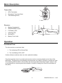
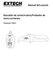
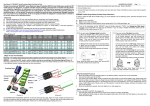
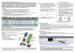
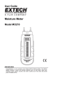
User Guide Circuit Breaker Finder/Receptacle Tester Model CB20 Introduction Thank you for selecting the Extech Model CB20. This device is shipped fully tested and calibrated and, with proper use, will provide years of reliable service. Please visit our website (www.extech.com) to check for the latest version of this User Guide. The Extech Instruments brand, a wholly owned subsidiary of FLIR Systems, Inc., is ISO-9001 certified. Safety International Safety Symbols This symbol, adjacent to another symbol or terminal, indicates the user must refer to the manual for further information. This symbol, adjacent to a terminal, indicates that, under normal use, hazardous voltages may be present Double insulation Safety Note Remove the battery if the device is to be stored for longer than 60 days. Cautions If the equipment is used in a manner not specified by the manufacturer, the protection provided by the equipment may be impaired. This product is designed for use by suitably qualified personnel familiar with electrical supply systems. Before using this product, read these instructions and safety warnings. Failure to comply with the safety warning or use of the unit in a manner not specified may result in serious injury or damage to equipment. Use in dry conditions Before use test that unit is functioning correctly. WARNING: Refer all indicated problems to a qualified electrician. 2 CB20-EU-EN V1.0 8/12 Meter Description Transmitter 1. GFCI Test button 2. Receptacle Test Code Chart 3. Test Indicating LED’s 1 2 3 Receiver 4. Battery Compartment 5. ON/OFF/RESET button 6. Low Battery LED 7. Indicating LED 8. Sensing Tip 9. Battery Cover Latch 8 7 6 5 4 9 Operation Functional Test Turn the receiver on and check that: 1. The Indicating LED is ON and Red. 2. The Low Battery LED is OFF. If either of these conditions does not exist, replace the battery Plug the transmitter into a live socket and move the receiver scanning head over the face of the transmitter. The frequency of the beeping should become very rapid or change to a continuous tone. The Indicating LED should turn Green when the scanning head is detecting a signal ”hotspot” (this is good practice for scanning since the indication is similar to finding the correct circuit breaker at the panel.) 3 CB20-EU-EN V1.0 8/12 Finding a Circuit Breaker The transmitter injects a signal onto the circuit which can be detected by the receiver. The receiver will beep and the indicating LED will change from red to green when the strongest signal is located. The receiver sensitivity automatically adjusts to minimize false identifications. 1. Plug the transmitter into the socket under test and the “correct” LEDs will turn on. 2. Go to the circuit breaker panel or fuse box and turn on the receiver. The Indicating LED on the receiver will light red to indicate automatic scan. 3. Place the sensing tip in contact with the face of the circuit breaker or fuses. Slowly run the sensing tip along the row of circuit breakers. Maintain a constant angle to the breakers as shown. The frequency of the beeping will increase to a very rapid or continuous tone and the LED will turn from red to green when the receiver encounters the breaker with the strongest signal. Continue the scan through all the breakers. 4. Repeat the scan of the row of breakers. With each sweep the receiver will automatically adjust its sensitivity and disregard weaker signals. 5. Continue scanning until the correct indication (rapid or continuous tone and green LED) is given only when the sensing tip is over one breaker or fuse. This is the breaker protecting the circuit that the transmitter is plugged into. 6. Turn the selected circuit breaker off and the receiver will revert to a red LED display. 7. Return to the tested socket and confirm that the correct breaker has been selected by checking that the LEDs on the transmitter are no longer ON (power is off). 8. Press and Hold the ON/OFF/RESET button to turn the Receiver OFF. Tips for automatic scanning The receiver works by comparing the strength of the signal received from one breaker to the next. Observe the following for best results. Important: The first strong signal encountered may not be the strongest there is. Do not stop scanning when a strong signal is first encountered. It is essential to continue scanning until all the breakers are tested to insure the correct breaker is located. Do not let the scanning head wander around. To operate well, the automatic scanning memory needs a consistent signal. Keep the red scanning head at the same angle relative to the breaker or fuses for the duration of the test. Keep the head in contact with the breaker during each sweep to ensure consistency in the proximity of the head to the breaker. Test only the same side of each breaker during a test. Pay particular attention to this when testing a vertically hung panel which may have neighboring breakers mounted in opposite directions. Always reset the receiver (away from the distribution board) before changing any test condition. 4 CB20-EU-EN V1.0 8/12 Alternate Scanning Techniques Due to the differing designs of circuit breakers it may sometimes be unclear from the above procedure which of two breakers the strongest signal comes from, particularly if it appears to come from a boundary area between two adjacent breakers. In the event of this occurring, one of the following variations should enable clear identification. A: Reset the receiver and scan the breakers on the opposite side of the switch. The strongest signal may be found at the top of the breaker. B: Reset the receiver and scan the breakers at a 90° angle to the original scan. At some point a stronger signal will be found; scan at the new angle. Receptacle Wiring Test 1. Plug the Transmitter / Receptacle tester into the outlet. 2. The three LED’s will indicate circuit condition. The diagram lists all of the conditions that the CB20 can detect. The LED’s in this diagram represent the view from the GFCI button side of the transmitter. When viewing the other side of the transmitter the LED’s will be a mirror image of those shown here. 3. The tester will not indicate the quality of the ground connection, 2 hot wires in a circuit, a combination of defects, or reversal of ground and neutral conductors. CORRECT WIRING GFCI TESTING IN PROGRESS HOT ON NEUTRAL WITH HOT OPEN HOT AND GROUND REVERSED HOT AND NEUTRAL REVERSED OPEN HOT OPEN NEUTRAL OPEN GROUND OFF ON Receptacle GFCI Test 1. Before using the tester, press the TEST button on the installed GFCI receptacle, the GFCI should trip. If it does not trip, do not use the circuit and call a qualified electrician. If it does trip, press the RESET button on the receptacle. 2. Plug the Transmitter / Receptacle tester into the outlet. Verify that the wiring is correct as described above. 3. Press and hold the test button on the tester for at least 8 seconds, the indicator lights on the tester will shut off when the GFCI trips. 4. If the circuit does not trip, either the wiring is incorrect, or the wiring is correct and the GFCI is defective. 5 CB20-EU-EN V1.0 8/12 Battery Replacement When the red low battery LED on the receiver turns on, the 9V battery must be replaced. To replace the battery: Press down on the battery cover latch then slide the cover to the rear and lift off. Replace the 9V battery. Reinstall the battery cover. Note: The transmitter is powered by the AC line and does not require a battery. All EU users are legally bound by the Battery Ordinance to return all used batteries to community collection points or wherever batteries / accumulators are sold! Disposal in household trash or refuse is prohibited! Disposal: Follow the valid legal stipulations in respect of the disposal of the device at the end of its lifecycle Other Battery Safety Reminders Never dispose of batteries in a fire. Batteries may explode or leak. Never mix battery types. Always install new batteries of the same type. Cleaning Wipe the exterior surface of the transmitter and receiver with a damp cloth or cleansing wipe. Do not use solvents. Dry thoroughly before use. 6 CB20-EU-EN V1.0 8/12 Specifications Operating Voltage 90 to 120VAC Operating Frequency 47 to 63Hz Power supply 9V battery (receiver) Operating Temperature 5ºC to 40ºC (41ºF to 104ºF) Storage Temperature -20 C to 60 C (-4 F to 140 F) Operating Humidity Max 80% up to 31ºC (87ºF) decreasing linearly to 50% at 40ºC (104ºF) Storage Humidity <80% Operating Altitude 2000 meters (7000ft.) maximum Weight Transmitter: 91g (3.2oz) Receiver: 136g (4.8oz) Dimensions Transmitter: 118 x 60 x 35mm (4.6 x 2.4 x 1.4”) Receiver: 196 x 55 x 36mm (7.7 x 2.2 x 1.4”) Approvals UL CE UL Listed The UL mark does not indicate that this product has been evaluated for the accuracy of its readings. o o o o Copyright © 2012 FLIR Systems, Inc. All rights reserved including the right of reproduction in whole or in part in any form ISO-9001 Certified www.extech.com 7 CB20-EU-EN V1.0 8/12


![User Manual [PDF 80.57KB]](http://vs1.manualzilla.com/store/data/005808718_1-0fabb64b5e1899e1380b2d49f3e9d3a7-150x150.png)