1
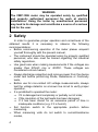
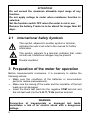
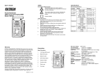
OPERATING INSTRUCTION
AC/DC DIGITAL CLAMP
METER
CMP-1006
Version 1.4
1
2
INTRODUTION...................................................... 3
SAFETY ................................................................... 4
2.1
3
INTERNATIONAL SAFETY SYMBOLS ...........................................6
PREPARATION OF THE METER FOR
OPERATION ........................................................... 6
FUNCTIONAL DESCRIPTION............................ 7
4
4.1
MEASUREMENT SOCKETS AND ELEMENTS OF SELECTION OF THE
MEASUREMENT FUNCTION....................................................................7
4.2 LCD DISPLAY .............................................................................8
4.3 TEST LEADS ................................................................................9
5
MEASUREMENTS................................................. 9
5.1
5.2
5.3
5.4
5.5
5.6
5.7
5.8
5.9
5.10
5.11
5.12
6
7
8
9
10
AC/DC CURRENT MEASUREMENTS ............................................9
AC AND DC VOLTAGE MEASUREMENTS ...................................11
RESISTANCE MEASUREMENTS ..................................................11
FREQUENCY OR % DUTY CYCLE MEASUREMENTS ....................12
TEMPERATURE MEASUREMENTS ..............................................12
CONTINUITY MEASUREMENTS .................................................13
DIODE MEASUREMENTS ...........................................................13
DATA HOLD FUNCTION .........................................................14
DC ZERO ................................................................................14
INRUSH FUNCTION ...................................................................14
LCD BACKLIGHT BUTTON .......................................................15
AUTOMATIC POWER OFF.........................................................15
BATTERY REPLACEMENT.............................. 15
CLEANING AND MAINTENANCE .................. 16
STORAGE ............................................................. 16
DISMANTLING AND UTILIZATION .............. 16
ATTACHMENTS.................................................. 17
10.1 TECHNICAL DATA .....................................................................17
10.2 STANDARD EQUIPMENT ............................................................19
10.3 MANUFACTURER ......................................................................19
2
1 Introdution
We appreciate your having purchased our digital clamp meter.
The CMP-1006 meter is a modern, high-quality measuring device,
which is easy and safe to use. Please acquaint yourself with the
present manual in order to avoid measuring errors and prevent
possible problems related to operation of the tester.
In the present manual we apply three kinds of warnings. These
are texts in frames, which describe possible dangers both for the
user and the meter itself. The messages starting from the word
‘WARNING:’ describe situations which imply a risk for life or health
should the recommendations presented in the present manual not
be observed. The word ‘ATTENTION!’ introduces a description of a
situation where non-observance of the recommendations presented
in the present manual may imply damage for the meter. Indications
of possible problems are preceded by the word ‘Attention:’.
WARNING:
Before using the instrument acquaint yourself with the
present manual and observe the safety regulations and
recommendations specified by the manufacturer.
WARNING:
The purpose of the CMP-1006 meter is to realise clamp
measurements of AC/DC current and also to realise AC/DC
voltage,
resistance,
frequency
and
temperature
measurements. Using the meter in a manner which does not
comply with the recommendations specified in the present
manual may lead to its damage and constitutes a source of a
serious risk for the user.
3
WARNING:
The CMP-1006 meter may be operated solely by qualified
and properly authorised personnel for work at electric
installations. Using the tester by unauthorised personnel
may lead to its damage and constitutes a source of a serious
risk for the user.
2 Safety
In order to guarantee proper operation and correctness of the
obtained results it is necessary to observe the following
recommendations:
• Before commencing operation of the meter please acquaint
yourself thoroughly with the present manual,
• The instrument should be operated solely by properly qualified
personnel, who also must be trained regarding the industrial
safety regulations,
• Use great care when making measurements if the voltages are
greater than 20VAC rms or 40VDC. These voltages are
considered a shock hazard,
• Always discharge capacitors and remove power from the device
under test before performing Diode, Resistance or Continuity
tests,
• Before use for non-contact AC voltage measurements, always
test the voltage detector on a known live circuit to verify proper
operation,
• It is prohibited to operated the meter:
⇒ If it is damaged and completely or partially out of order,
⇒ If the insulation of the test leads has been damaged,
⇒ If it has been stored for an excessive period of time in
inadequate conditions (e.g. if it is humid),
• Set function switch to the appropriate position before
measuring,
• When measuring volts do not switch to current/resistance
modes,
4
•
•
•
•
Do not measure current on a circuit whose voltage exceeds
600V,
When changing ranges always disconnect the test leads from
the circuit under test,
If the equipment is used in a manner not specified by the
manufacturer, the protection provided by the equipment may be
impaired,
Repairs must be realised solely by an authorised service
workshop.
ATTENTION!
Input Limits
Function
A DC, A AC
V DC, V AC
Resistance, Frequency, Diode
Test
Temperature (°C/°F)
Maximum Input
1000A DC/AC
600V DC/AC
250V DC/AC
60V DC, 24V AC
WARNING:
Do not realise measurements with wet hands.
WARNING:
Do not realise measurements in environments in which there
are inflammable gases. Otherwise operation of the meter
under such conditions may cause sparking and explosion.
5
ATTENTION!
Do not exceed the maximum allowable input range of any
function.
Do not apply voltage to meter when resistance function is
selected.
Set the function switch OFF when the meter is not in use.
Remove the battery if meter is to be stored for longer than 60
days.
2.1
International Safety Symbols
This symbol, adjacent to another symbol or terminal,
indicates the user must refer to the manual for further
information.
This symbol, adjacent to a terminal, indicates that, under
normal use, hazardous voltages may be present
Double insulation
3 Preparation of the meter for operation
Before measurements commence, it is necessary to realise the
following actions:
• Make sure the conditions of the batteries or accumulators
permit to realise measurements,
• Make sure the casing of the meter and the insulation of the test
leads are not damaged,
• Insert the black test lead into the negative COM terminal and
the red test lead into the V·Ω· oC· oF·Hz positive terminal.
WARNING:
Connection of inappropriate or damaged test leads
constitutes a risk of an electric shock with a dangerous
voltage.
6
4 Functional description
4.1
Measurement sockets and elements of
selection of the measurement function
1
A
2
A
6
3
4
DC
AC
¡C
ã
¡ã
F
A
mV
kM
5
1.
Current clamp
7
2.
Clamp opening trigger
3.
Control buttons:
a. Backlight
b. Inrush / Mode
c. Maks. / Min.
d. Data Hold
e. Hz / % / DC Zero
4.
Backlit LCD Display
5.
COM negative input jack for black test lead
6.
Rotary function switch
7.
V·Ω
Ω ·°C·°F·Hz positive input jack for red lead
4.2
LCD display
HOLD
- Data Hold
Minus sign
- Negative reading display
0 do 6600
- Measurement display digits
DC ZERO
- DCA Zero
MAKS/MIN
- Maximum/Minimum
INRUSH
- Inrush Current
AUTO
- Auto Range mode
DC/AC
- Direct Current / Alternating Current
- Low battery
mV lub V
8
- Milli-volts or Volts (Voltage)
Ω
- Ohms (Resistance)
A
- Amperes (Current)
F
- Farad (Capacitance)
Hz
- Hertz (Frequency)
o
- Fahrenheit and Celsius units (Temperature)
F i oC
n, m, µ, M, k - Unit of measure prefixes: nano, milli, micro, mega,
and kilo
·)))
- Continuity test
- Diode test
4.3
Test leads
The manufacturer guarantees correct measurement indications
provided original test leads are used.
WARNING:
Connection of inadequate test leads constitutes a risk of
electric shock with a dangerous voltage or may be a cause of
measurement errors.
5 Measurements
It is recommended to get acquainted thoroughly with the
contents of the present chapter since it describes the measurement
systems, the manner of realisation of measurements and the basic
principles of interpretation of the results. Set the function select
switch to the OFF position when the meter is not in use.
5.1
AC/DC current measurements
WARNING:
Do not measure current on a circuit whose voltage exceeds
600V AC. Do not take current readings on circuits where the
maximum current potential is not known. Do not exceed the
9
maximum allowable input range while measuring current.
WARNING:
Do not realise measurements if the battery compartment is
open.
WARNING:
Do not commence measurements if the test leads are
connected to the meter.
In order to realise a measurement of current, it is necessary to
realise the following actions:
•
Set the Function switch to the 1000A or 660A range. If the
approx. range of the measurement is not known, select the
highest range then move to the lower ranges if necessary,
•
Press the DC ZERO button to zero the meter display,
•
Press the trigger to open jaw. Fully enclose only one wire. For
optimum results, center the wire in the jaw,
•
Read the result of the measurement on the display.
Attention:
During measurements of the current make sure the clamp is
properly placed. Otherwise the results of the measurements
will not be exact. The most exact result we will get if the wire
is placed in the middle of clamp.
10
5.2
AC and DC voltage measurements
WARNING:
Do not realise measurements if the battery compartment is
open.
In order to realise a measurement of AC or DC voltage, it is
necessary to realise the following actions:
•
Insert the black test lead into the negative COM terminal and
the red test lead into the positive V·Ω
Ω ·°C·°F·Hz terminal,
•
Set the function switch to the V Hz position,
•
Use the MODE button to select AC or DC Voltage,
•
Connect the test leads in parallel to the circuit under test,
•
Read the voltage measurement on the LCD display.
5.3
Resistance measurements
WARNING:
Measurements must not be realised in live circuits.
Capacitors must be discharged.
WARNING:
Do not realise measurements if the battery compartment is
open.
In order to realise a measurement of the resistance it is
necessary to realise the following actions:
•
Insert the black test lead into the negative COM terminal and
the red test lead into the V·Ω
Ω ·°C·°F·Hz positive terminal,
•
Set the function switch to the Ω •)))
position,
•
Touch the test probe tips across the circuit or component
under test; it is best to disconnect one side of the device under
11
•
5.4
test so the rest of the circuit will not interfere with the
resistance reading,
Read the resistance on the LCD display.
Frequency or % duty cycle
measurements
In order to realise frequency or % duty cycle measurement it is
necessary to realise the following actions:
•
Insert the black test lead banana plug into the negative COM
jack and the red test lead banana plug into the V·Ω
Ω ·°C·°F·Hz
positive jack,
•
Set the function switch to the V Hz position,
•
Press the Hz/% button to select the Frequency (Hz) or Duty
cycle (%)function,
•
Touch the test probe tips across the circuit under test,
•
Read the Frequency value on the display,
•
Duty cycle measurement: When the duty cycle is less than
10.0%, the LCD panel shows UL. When the duty cycle is more
than 94.9%, the LCD panel shows OL,
•
The display will indicate the proper decimal point and value,
•
Press the HZ/% button again to return to the voltage mode.
5.5
Temperature measurements
In order to realise temperature measurement it is necessary to
realise the following actions:
•
Set the function switch to the Temp position,
•
Insert the Temperature Probe into the negative COM and the
V·Ω
Ω ·°C·°F·Hz positive jacks, observing polarity,
•
Touch the Temperature Probe head to the device under test.
Continue to touch the part under test with the probe until the
reading stabilizes,
•
Read the temperature on the display. The digital reading will
indicate the proper decimal point and value,
•
Use the MODE button to select oF or oC.
12
WARNING:
To avoid electric shock, be sure the thermocouple has been
removed before changing to another measurement function.
5.6
Continuity Measurements
WARNING:
Measurements must not be realised in live circuits.
Capacitors must be discharged.
WARNING:
Do not realise measurements if the battery compartment is
open.
In order to realise continuity test it is necessary to realise the
following actions:
•
Insert the black test lead into the negative COM terminal and
the red test lead into the V·Ω
Ω ·°C·°F·Hz positive terminal,
•
Set the function switch to the Ω •)))
position,
•
Use the MODE button to select continuity “•)))”. The display
icons will change when the MODE button is pressed,
•
Touch the test probe tips across the circuit or component
under test,
•
If the resistance is < 40Ω, a tone will sound.
5.7
Diode Measurements
In order to realise diode test it is necessary to realise the
following actions:
•
Insert the black test lead banana plug into the negative COM
jack and the red test lead banana plug into the V·Ω
Ω ·°C·°F·Hz
positive jack,
13
•
•
•
•
Turn the function switch to Ω •)))
position. Use the MODE
button to select the diode function if necessary (diode symbol
will appear on the LCD when in Diode test mode),
Touch the test probe tips to the diode or semiconductor
junction under test. Note the meter reading,
Reverse the test lead polarity by reversing the red and black
leads. Note this reading,
The diode or junction can be evaluated as follows:
⇒ If one reading displays a value (typically 0.400V to 0.900V)
and the other reading displays OL, the diode is good;
⇒ If both readings display OL the device is open;
⇒ If both readings are very small or ‘0’, the device is shorted.
5.8
DATA HOLD Function
To freeze the LCD reading, press the HOLD button. While data
hold is active, the HOLD icon appears on the LCD. Press the HOLD
button again to return to normal operation.
5.9
DC ZERO
The DC ZERO is a relative feature and can be used in a
measurement of DC current.
•
Press the DC ZERO button to zero the display. “ZERO” will
appear in the display. The displayed reading is now the actual
value less the stored “zero” value;
•
To exit this mode, press and Hold the ZERO button until
“ZERO” is no longer in the display.
5.10
Inrush Function
The Inrush current function for AC current measurement to
detect the starting-up current of a motor. In ACA modes, press
INRUSH button will force meter to enter INRUSH mode. Then LCD
Displays ”- - - -” until the motor starting up an being detected. The
detection will be done only one time and the output reading will be
hold. To exit INRUSH mode, press INRUSH button more than one
second.
14
5.11
LCD Backlight Button
The LCD is equipped with backlighting for easier viewing,
especially in dimly lit areas. Press the backlight button to turn the
backlight on. Press again to turn the backlight off. Note that the
meter does have an auto power off feature as described below.
5.12
Automatic Power OFF
In order to conserve battery life, the meter will automatically turn
off after approximately 25 minutes. To turn the meter on again, turn
the function switch to the OFF position and then to the desired
function position.
6 Battery replacement
The CMP-1006 meter is supplied by means of one 9V battery. It
is recommended to use alkaline battery.
Attention:
When making measurements with a battery's mnemonic on,
one must take into account additional indefinite
measurement uncertainty or unstable working of the meter.
WARNING:
Should the test leads be left in the sockets during
replacement of the battery, there might be a risk of electric
shock with a dangerous voltage.
In order to replace the battery it is necessary to do the following:
•
Remove the Phillips head screw that secures the rear battery
door,
•
Open the battery compartment,
•
Replace the 9V battery,
•
Secure the battery compartment.
15
7 Cleaning and maintenance
The casing of the meter may be cleaned with a soft, damp cloth
using all-purpose detergents. Do not use any solvents or cleaning
agents which might scratch the casing (powders, pastes, etc.).
The electronic system of the meter does not require maintenance.
8 Storage
In the case of storage of the device, the following
recommendations must be observed:
•
Disconnect all the test leads from the meter,
•
Make sure the meter and its accessories are dry,
•
In the case the meter is to be stored for a prolonged period of
time, the battery must be removed from the device.
9 Dismantling and utilization
Worn-out electric and electronic equipment should be gathered
selectively, i.e. it must not be placed with waste of another kind.
Worn-out electronic equipment should be sent to a collection
point in accordance with the law of worn-out electric and electronic
equipment.
Before the equipment is sent to a collection point, do not
dismantle any elements.
Observe the local regulations concerning disposal of packages,
worn-out batteries and accumulators.
16
10 Attachments
10.1
Technical data
„m.v.” means measured value of standard
Function
Range &
Resolution
AC Current
True RMS (45 Hz
to 65 Hz)
660.0A
1000A
±(2.5% m.v. + 8 digits)
660.0A
±(2.5% m.v. + 5 digits)
1000A
±(2.8% m.v. + 8 digits)
DC Current
Basic Accuracy
±(2.8% m.v. + 8 digits)
6.600V
DC Voltage
66.00V
±(1.5% m.v. + 3 digits)
600.0V
AC Voltage
True RMS (45 Hz
to 65 Hz)
6.600V
66.00V
±(1.8% m.v. + 5 digits)
600.0V
660.0Ω
±(1.0% m.v. + 4 digits)
6.600KΩ
Resistance
66.00KΩ
±(1.5% m.v. + 2 digits)
660.0KΩ
Frequency
6.600MΩ
±(2.5% m.v. + 3 digits)
66.0MΩ
±(3.5% m.v. + 5 digits)
±(1.2% m.v. + 2 digits)
Sensitivity:
30…5kHz:10Vrms min.
5kHz…15kHz: 40Vrms
0,660…6,599kHz
min.
30,0…659,9Hz
17
6,60…15,00kHz
@ 20% to 80% duty
cycle
10.0…94.9%
unspecificated
Pulse width: 100µs…100ms,
Frequency: 30Hz…15kHz;
Sensitivity: 30…5kHz:10Vrms min.
5kHz…15kHz:40Vrms min.
Duty Cycle
Temperature
(probe accuracy
not included)
-20 to 760°C
o
-4 do 1400 F
±(3.0% m.v. + 5 °C)
±(3.0% m.v. + 9 °F)
Other technical data:
a)
b)
c)
d)
e)
f)
g)
h)
i)
j)
k)
l)
m)
n)
o)
p)
q)
r)
18
Measurement category ..........III 600V according to EN 61010-1
Clamp jaw opening………………....34mm (1.34") approximately
Internal diameters of clamp...…….………36x52mm (1,42x2,05”)
Display……………………………………6600 counts backlit LCD
Continuity check…………..threshold 40Ω; Test current < 0.5mA
Diode test……………………………test current of 0.3mA typical;
open circuit voltage < 3VDC typical
Low Battery indication…………………………..‘BAT’ is displayed
Over-range indication…………………………….‘OL’ is displayed
Measurement rate……………….2 readings per second, nominal
Inrush……………………………………….integration time 100ms
Temperature sensor…………………………type K thermocouple
Input Impedance…………………….……..10MΩ (VDC and VAC)
AC bandwidth……………………….50 to 400Hz (AAC and VAC)
Operating temperature……………...5oC to 40oC (41oF to 104oF)
Storage temperature……………….-20oC to 60oC (-4oF to 140oF)
Operating humidity………………….max 80% up to 31oC F (87o)
decreasing linearly to 50% at 40oC (104oF)
Storage humidity………………………………………………<80%
Operating altitude………………………2000m (7000ft) maximum
s)
t)
u)
v)
Battery………………………………………………..one 9V battery
Auto power OFF………………….after approximately 25 minutes
Dimensions…………………...229 x 80 x 49mm (9.0 x 3.1 x 2.0")
Weight……………………………………………………………303g
Attention:
For indoor use and in accordance with the requirements for
double insulation to IEC1010-1 (1995): EN61010-1 (1995)
Overvoltage Category III 600V, Pollution Degree 2.
10.2 Standard equipment
The standard set provided by the manufacturer includes the
following components:
• The CMP-1006 meter,
• Test leads (2 pieces),
• K Type temperature probe,
• 9V battery,
• Operating manual,
• Carrying case,
• Guarantee card.
10.3 Manufacturer
The manufacturer of the device, which also provides guarantee
and post-guarantee service is the following company:
SONEL S. A.
ul. Wokulskiego 11
58-100 Świdnica
Tel: + 48 74 858 38 60
Fax: +48 74 858 38 09
E-mail: [email protected]
Web page: www.sonel.pl
19
Service repairs
manufacturer.
must
Note:
be realised
solely
Made in China for SONEL S.A.
20
by
the