1
m
User Manual
s.
co
Configuring and Installing the INTERBUS
Loop 2 and INTERBUS S-Line Product
Range
Designation: IB L2 SYS PRO UM E
on
l
in
ec
om
po
ne
nt
Order No.:
27 43 49 1
s.
nt
ne
po
om
in
ec
on
l
co
m
Revision:
C
Order No.:
27 43 49 1
nt
IB L2 SYS PRO UM E
in
ec
om
po
ne
Designation:
s.
co
m
Configuring and Installing the INTERBUS Loop 2 and
INTERBUS S-Line Product Range
on
l
This manual is valid for:
Modules of the INTERBUS Loop 2 and INTERBUS S-Line product range
© PHOENIX CONTACT 08/2002
5796C
s.
nt
ne
po
om
in
ec
on
l
co
m
Please Observe the Following Notes:
In order to guarantee the safe use of your device, we recommend that you
read this manual carefully. The following notes give you information on
how to use this manual.
m
Requirements of the User Group
nt
s.
co
The use of products described in this manual is oriented exclusively to
qualified electricians or persons instructed by them, who are familiar with
applicable national standards. Phoenix Contact assumes no liability for
erroneous handling or damage to products from Phoenix Contact or external products resulting from disregard of information contained in this manual.
ne
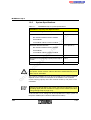
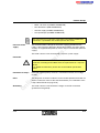
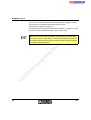
Explanation of Symbols Used
om
po
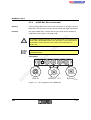
The attention symbol refers to an operating procedure which, if not carefully followed, could result in damage to equipment or personal injury.
on
l
in
ec
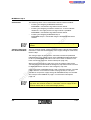
The note symbol informs you of conditions that must strictly be observed
to achieve error-free operation. It also gives you tips and advice on hardware and software optimization to save you extra work.
The text symbol refers to detailed sources of information (manuals, data
sheets, literature, etc.) on the subject matter, product, etc. This text also
provides helpful information for the orientation in the manual.
We Are Interested in Your Opinion
We are constantly attempting to improve the quality of our manuals.
Should you have any suggestions or recommendations for improvement
of the contents and layout of our manuals, we would appreciate it if you
would send us your comments. Please use the universal fax coupon at the
back of the manual for this.
5796C
Short Designation
Statement of Legal Authority
This manual, including all illustrations contained herein, is copyright protected. Use of this manual by any third party in departure from the copyright provision is forbidden. Reproduction, translation, or electronic or
photographic archiving or alteration requires the express written consent
of Phoenix Contact. Violations are liable for damages.
on
l
in
ec
om
po
ne
nt
s.
co
m
Phoenix Contact reserves the right to make any technical changes that
serve the purpose of technical progress.
5796C
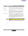
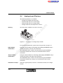
About This Manual
This manual illustrates how to configure a Loop 2 system to meet your
application requirements.
Who should use this
manual
Use this manual if you are responsible for configuring and installing a
Loop 2 system within INTERBUS. This manual is written based on the
assumption that the reader possesses basic INTERBUS knowledge.
Related
documentation
For additional information regarding INTERBUS in general, refer to the
"General Introduction to the INTERBUS System" User Manual.
co
m
Purpose of this
manual
nt
s.
The manual mentioned above may be ordered directly from Phoenix Contact.
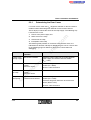
Order Designation
ne
Description
on
l
5796C
IBS SYS INTRO G4 UM E
27 45 21 1
om
Make sure you are always working with the latest documentation published. Changes in or additional information on present documentation
can be found on the Internet at www.phoenixcontact.com. The Phoenix
Contact homepage is updated daily.
in
ec
Current
documentation on
the Internet
po
General Introduction to the
INTERBUS System
Order No.
Short Designation
The manual starts with the main table of contents that gives you an
overview of all manual topics.
–
Each manual section starts with an overview of the section topics.
–
On the left side of the pages within the sections you will see the topics
that are covered in the section.
–
In the appendix you will find a list of figures and a list of tables. The
index helps you find the term you are looking for.
–
At the end of this manual you will find explanations of typical
INTERBUS terms and abbreviations used in this manual.
co
m
–
The first section of this manual introduces you to the Loop 2 basics.
The following sections contain general information that applies to all modules or module groups of the INTERBUS Loop 2 and INTERBUS S-Line
product range. Topics are, for example:
ne
nt
This user manual
includes
For easy orientation when looking for specific information the manual
offers the following help:
s.
Orientation in this
manual
Overview of the product groups
–
Structure of the modules
–
Module installation and connection
–
Troubleshooting and debugging
–
Common technical data
om
po
–
on
l
Validity of
documentation
in
ec
If you need specific information on a module refer to the module-specific
data sheets.
This manual contains a description of the modules that were available
when the manual was published.
Phoenix Contact reserves the right to make any technical extensions and
changes to the system that serve the purpose of technical progress. Up to
the time that a new manual revision is published, any updates or changes
will be documented on the Internet at www.phoenixcontact.com.
5796C
Table of Contents
1 Integration of Loop 2 Into the INTERBUS System............................................1-3
The INTERBUS System..............................................................1-3
1.2
The INTERBUS Installation System as the Basis
of the INTERBUS System ...........................................................1-9
1.3
INTERBUS S-Line as Part of the INTERBUS Loop System .....1-17
co
m
1.1
s.
2 Product Groups.................................................................................................2-3
Loop 2 Bus Terminal Module .....................................................2-3
2.2
Loop 2 Branch Terminal..............................................................2-6
2.3
Digital Loop 2 Devices ................................................................2-7
2.4
Analog Loop 2 Devices ...............................................................2-9
2.5
Loop 2 Motor Starter .................................................................2-12
2.6
Loop 2 Power Module ...............................................................2-14
2.7
INTERBUS S-Line.....................................................................2-15
om
po
ne
nt
2.1
on
l
in
ec
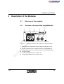
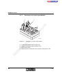
3 Description of the Modules ...............................................................................3-3
3.1
Structure of the modules .............................................................3-3
3.2
Dimensions of the Modules.........................................................3-8
3.3
Labeling of I/O Modules ............................................................3-16
3.4
Diagnostic and Status Indicators...............................................3-17
4 Mounting and Connecting Modules ..................................................................4-3
5796C
4.1
General Information on INTERBUS Installation ..........................4-3
4.2
Loop 2 Installation .......................................................................4-8
4.3
Mounting Loop 2 Modules.........................................................4-13
4.4
Connecting Cables....................................................................4-15
4.5
Shielding of Analog Sensors and Actuators..............................4-31
1
Product Short Designation
4.6
Connecting Loop 2 Motor Starter ..............................................4-35
4.7
Mounting and Connecting S-Line Modules ...............................4-42
4.8
Initial Startup .............................................................................4-48
4.9
Measuring Voltage Drop ...........................................................4-51
4.10
Connecting Sensors and Actuators...........................................4-54
m
5 Error Localization and Removal........................................................................5-3
General Information on Localization of an Error .........................5-3
5.2
Failure of the Loop Supply ..........................................................5-4
s.
co
5.1
nt
6 Technical Data..................................................................................................6-3
System Data................................................................................6-3
6.2
Technical Data ............................................................................6-7
6.3
Technical Data of the Cable Types ...........................................6-14
po
ne
6.1
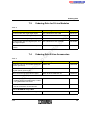
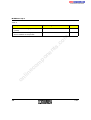
7 Ordering Data ...................................................................................................7-3
7.2
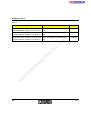
Ordering Data for Loop 2 Accessories ........................................7-4
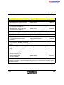
Ordering Data for S-Line Modules ..............................................7-5
A
B
on
l
in
ec
7.3
Ordering Data for Loop 2 Modules..............................................7-3
om
7.1
7.4
Ordering Data S-Line Accessories..............................................7-5
7.5
Ordering Data for Documentation .............................................7-10
List of Devices of an INTERBUS Loop 2 System ......................................... A-1
A1
Loop 2 Device List..................................................................... A-2
A2
S-Line Module Device List ........................................................ A-4
Lists............................................................................................................... B-1
B1
2
List of Figures............................................................................ B-1
5796C
Section 1
This section informs you about
–
the INTERBUS system
–
the INTERBUS installation system
–
the INTERBUS Loop 2 product range
–
the INTERBUS S-Line product range
The INTERBUS System..............................................................1-3
1.3
s.
The INTERBUS Installation System as the Basis
of the INTERBUS System ...........................................................1-9
Product Ranges of the Installation System ....................1-9
1.2.2
Features of the Installation System..............................1-10
1.2.3
Loop 2 as a Component of the
INTERBUS Installation System....................................1-12
1.2.4
Loop 2 Product Description..........................................1-14
1.2.5
System Specifications..................................................1-16
nt
1.2.1
ne
1.2
Example Topology of an INTERBUS System ................1-4
co
1.1.1
po
1.1
m
Integration of Loop 2 Into the INTERBUS System................................................1-3
INTERBUS S-Line as Part of the INTERBUS Loop System .....1-17
S-Line Product Description ..........................................1-18
om
1.3.1
S-Line Example Topology............................................1-19
on
l
in
ec
1.3.2
5796C
1-1
1-2
5796C
s.
nt
ne
po
om
in
ec
on
l
co
m
Integration of Loop 2 Into the INTERBUS System
1
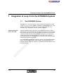
Integration of Loop 2 Into the INTERBUS System
1.1
The INTERBUS System
s.
From the controller board, all devices are connected to the bus system.
Each device has two separate lines for data transmission: one for forward
data transfer and one for return data transfer. This eliminates the need for
a return line from the last to the first device, necessary in a simple ring
system. The forward and return lines run in one bus cable. From the
installation point of view, INTERBUS has a tree structure as only one cable
leads from one device to the next.
ne
nt
Forward and return
line in one cable
co
m
INTERBUS is a serial bus system, which transmits data between control
systems (e.g., PCs, PLCs, VMEbus computers, robot controllers etc.) and
spatially distributed I/O modules that are connected to sensors and
actuators (e.g., temperature sensors, position switches).
on
l
in
ec
om
po
In the INTERBUS topology the single bus devices can be differentiated by
means of their position in the system. There are controller boards, bus
terminal modules, remote bus devices, installation remote bus devices and
local bus devices.
5796C
1-3
INTERBUS Loop 2
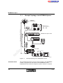
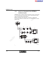
1.1.1
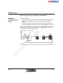
Example Topology of an INTERBUS System
IN T E R B U S
c o n tr o lle r b o a r d
2 4 V
IN
O U T
m
2 4 V
IN
O U T
IN T E R B U S L o o p 2
IN
O U T
s.
[7 .9 5 m i.])
IN
O U T
po
ne
nt
IN T E R B U S S T c o m p a c t s ta tio n
on
l
in
ec
om
(m a x . 1 2 .8 k m
[1 3 1 2 .3 4 ft.])
R e m o te b u s
IB S L B O X 2 4 D I 4 /4 M 1 2 -D -2
B u s s e g m e n t (m a x . 4 0 0 m
(6 5 6 .1 7 ft.)
co
m a x . 2 0 0 m
1-4
R D
T R
U L
U S
D
1
2
1
1
2
1
2
D
1
2
D
1
2
D
1
2
2
U L
D
E
E
U M
D O 8
D I2
D I2
D I2
P W
R
IN /F
In lin e s ta tio n
L 2
m a x . 2 0 m
(6 5 .6 2 ft.)
2 4 V
IN
IN
O U T
IN
O U T
T E R
B
U S
X 3 0
IN T E R B U S
L O O P IN
IN
O U T
D IA G
U S
X 3 1
IN T E R B U S
L O O P O U T
M 1
M 2
M 3
M 4
IN T E R B U S L o o p 2
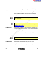
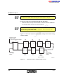
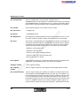
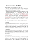
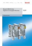
Figure 1-1
Controller board
B A
R C
5 7 9 6 B 1 0 1
Example topology of the INTERBUS system
The controller board takes over the master function in the INTERBUS
network. It organizes the data traffic in the INTERBUS system,
independent of the control or computer system in which it is installed.
5796C
Integration of Loop 2 Into the INTERBUS System
Controller boards are available for a wide range of control and computer
systems. These are listed in the "INTERBUS Addressing" Data Sheet
(DB GB IBS SYS ADDRESS, Part No. 90 00 99 0)
Tasks of the controller board:
–
Reading the input data from the input modules
–
Monitoring INTERBUS
–
Sending error messages to the host system
–
Indicating diagnostic messages
–
Controlling the cyclic I/O protocol
s.
co
m
Transmitting output data to the output modules
nt
The first step in setting up a modular system is to connect the bus terminal
module to the INTERBUS remote bus cable. I/O modules (or also power
modules and function modules) may be installed branching off from this
bus terminal module, to create a local bus.
ne
Bus terminal module
–
om
po
A bus terminal module divides the system into segments, thus allowing you
to switch off single branches during operation. In addition, the bus terminal
module supplies communications voltage to the module electronics of the
connected modules.
in
ec
A bus terminal module must be supplied with non-interruptible voltage. This
means that the voltage may not be off at the same time as the subsystem
if the whole bus system is to continue operation. A failure of the supply
voltage on the bus terminal module stops the system and causes an error
message for the bus segment.
on
l
Tasks of the bus terminal module:
5796C
–
Coupling the remote bus and local bus
–
Supplying the modules with communications voltage
–
Updating the data signal (repeater function)
–
Electrical isolation of the bus segments
–
Connecting or disconnecting the local bus and the outgoing remote bus
via firmware
–
If required, reporting errors via an electrically isolated alarm output
(e.g., sound signal, light signal)
1-5
INTERBUS Loop 2
Remote bus
The remote bus connects the controller board with the remote bus devices
and the remote bus devices with each other.
Remote bus devices are bus terminal modules, certain modules or a
mixture of both. Each has a local voltage supply and an electrically isolated
outgoing INTERBUS segment.
m
The maximum number of remote bus devices on INTERBUS is limited to
254.
In addition to the data transmission lines, the remote bus can also carry the
voltage supply line for the connected devices, the sensors and analog
actuators. This network cabling is referred to as installation remote bus.
Local bus
A local bus is a bus connection that branches off from a remote bus via a
bus terminal module and connects the local bus devices with each other.
The bus terminal supplies the connected devices with communications
voltage. The switching voltage for the outputs must be connected
separately to the output modules.
ne
nt
s.
co
Installation remote
bus
po
Local bus devices are I/O devices used to set up a decentralized substation
in the control cabinet or in the field. The devices are connected to the
remote bus via a bus terminal module. Within the local bus, branching is
not allowed.
The installation local bus connects INTERBUS Loop devices or INTERBUS
Loop 2 devices.
on
l
in
ec
Installation local bus
om
The maximum number of local bus devices depends on the bus terminal
module used.
1-6
The installation local bus is used to network distributed sensors and
actuators on machines or in systems. Individual I/O devices with
corresponding module electronics can also be connected to the installation
local bus (Loop or Loop 2).
5796C
Integration of Loop 2 Into the INTERBUS System
INTERBUS Loop
INTERBUS Loop (Loop) is connected to the remote bus using a bus
terminal module. The bus terminal module converts the signals from the
remote bus to the installation local bus and provides the supply voltage for
the Loop. Up to 32 Loop devices can be connected to a bus terminal
module using a two-wire twisted unshielded cable which transfers data and
supplies power to the connected devices.
s.
co
m
In a Loop system Loop 2 modules can only be used with firmware
version 4.4x or later.
INTERBUS Loop 2 (Loop 2) is a further development of INTERBUS Loop.
It features extended technical parameters and more extensive diagnostics.
po
INTERBUS Loop 2
ne
nt
For additional information on INTERBUS Loop, please refer to the
"Configuring and Installing the INTERBUS Loop Product Range" User
Manual (IB SL SYS PRO UM E) on the Internet at
www.phoenixcontact.com.
om
With Loop 2 up to 63 INTERBUS Loop 2 devices can be connected to a
bus terminal module using a two-wire twisted unshielded cable which
transfers data and supplies power to the connected devices.
on
l
in
ec
In the same way as INTERBUS Loop, Loop 2 topologically represents an
installation local bus. The installation local bus is integrated into an
INTERBUS remote bus via a bus terminal module or into an Inline station
via a local bus branch terminal.
INTERBUS Inline
Loop modules are not to be used in a Loop 2 system.
INTERBUS Loop 2 and INTERBUS Inline are the basis of the
Phoenix Contact INTERBUS installation system.
Only Loop 2 can be integrated into an Inline station. Loop 2 is connected
using a local bus branch terminal (Loop 2 branch terminal).
5796C
1-7
INTERBUS Loop 2
The bus terminal module (in the remote bus) or the branch terminal (within
the Inline station) converts INTERBUS signals to the bus physics of Loop 2
and provides the supply voltage. For general technical data about
INTERBUS Inline please refer to Section 6.1.3, "INTERBUS Inline System
Data".
co
m
For additional information on the Inline product range, please refer to the
"Configuring and Installing the INTERBUS Inline Product Range" User
Manual (IBS IL SYS PRO UM E, Order No. 27 43 04 8).
A remote bus branch is a branch off the remote bus. A branch is connected
to the main line of the remote bus via a special bus terminal module. This
bus terminal module allows the connection and disconnection of the
branching bus segment.
Bus segment
A bus segment consists of a remote bus device and the I/O modules
connected to it. The preceding cable is also part of the segment.
I/O modules
I/O modules connect INTERBUS to the sensors and actuators.
po
ne
nt
s.
Remote bus branch
on
l
in
ec
om
For additional information on the INTERBUS topology, please refer to
the "General Introduction to the INTERBUS System" User Manual
(IBS SYS INTRO G4 UM E, Order No. 27 45 21 1).
1-8
5796C
Integration of Loop 2 Into the INTERBUS System
1.2
The INTERBUS Installation System as the
Basis of the INTERBUS System
co
m
The INTERBUS installation system offers mechanical engineers and
system builders an automation system with decentralized control. The
INTERBUS system has the standard functions required to meet the needs
of virtually any automation system. INTERBUS Inline and INTERBUS
Loop 2 from Phoenix Contact are the basis for the INTERBUS installation
system.
1.2.1
Product Ranges of the Installation System
ne
The INTERBUS Inline product range is a modular automation system that
is integrated into the INTERBUS system. With Inline automation terminals
you can easily add one terminal to the next and build functional units that
meet your automation requirements. These functional units make the
classical and module-oriented control cabinet redundant.
po
INTERBUS Inline
s.
The installation system consists of standardized functions, uniform
interfaces, and easy connections.
nt
Definition
in
ec
om
The Inline system contains automation terminals for all standard functions,
like digital and analog input and output, control, pneumatics, safety,
hydraulics and motor starters.
on
l
INTERBUS Loop 2
INTERBUS Loop 2 can be directly connected to the INTERBUS remote
bus using a bus terminal module or to an Inline station using a Loop 2
branch terminal. In this way, the sensors and actuators in the field are
networked with the Inline station in the control box.
The individual input and output modules with IP 65/IP 67 protection are
connected using a two-wire twisted unshielded Loop cable. The modules
are connected to the bus using the QUICKON connection method. Sensors
and actuators are connected via M12 connectors.
Modules with digital and analog inputs and outputs and motor starters are
available within the Loop 2 product range (see "Versions"on page 1-14).
INTERBUS S-Line
5796C
INTERBUS S-Line is based on the INTERBUS Loop 2 functionality. It has
been especially developed for use on small and mid-sized machines. In
order to place I/O modules as close as possible to sensors and actuators
a new cabling system has been designed for meeting the requirements of
1-9
INTERBUS Loop 2
mechanical engineering. Preassembled and tested cables with M12
circular connectors are used as S-Line bus cables. Sensors and actuators
are connected to input and output modules (with IP 65/IP 67 protection)
using M8 connectors.
1.2.2
The basic idea of the installation system is distributing the inputs and
outputs in the field and creating function blocks in order to optimize the
application. After the I/O points have been decentralized, the required
standardized functions can now be created. The individual function blocks
that are created with INTERBUS Inline can be installed in terminal boxes
directly in the field. A control component (distributed intelligence, e.g.,
Inline controller) can be integrated in the function blocks. This makes it
possible to combine machines and systems modularly in small groups.
That means, the central control system is divided into small distributed
units in the machine or the system. Apart from the control component,
special function modules, pneumatic modules, safety modules, power
modules, hydraulic modules, etc. can be integrated into the Inline station.
All functions move from the control cabinet directly into the field.
po
ne
nt
s.
co
m
Standardized
functions
Features of the Installation System
on
l
Seamless bus
in
ec
om
Signals of modular machine and system parts close to the Inline station can
be processed in the distributed control system with INTERBUS Loop 2.
Loop 2 can be integrated into the Inline station via a Loop 2 branch
terminal.
Easy connection
1-10
The INTERBUS installation system features a seamless communication
from the sensor to the control system via INTERBUS. Neither INTERBUS
Inline nor INTERBUS Loop 2 require a gateway or link solution.
Every Loop 2 device is an INTERBUS network device and contains a
separate INTERBUS Loop 2 protocol chip (LPC2). Every Inline automation
terminal also is an INTERBUS network device with a separate INTERBUS
protocol chip (SUPI III OPC).
You need just one configuration and startup software package for the entire
installation system, e.g., CMD for standard controller boards or PC WORX
when using a Field Controller (e.g., Inline controller).
Connecting the individual components of the installation system can be
described in three words: "Automation without wiring".
5796C
Integration of Loop 2 Into the INTERBUS System
With INTERBUS Inline the complex wiring of individual terminal points that
was necessary in control cabinets is replaced by simply connecting the
Inline automation terminals together. When an Inline station is installed
correctly, I/O power and data circuits are automatically created.
m
The INTERBUS Inline I/O devices are connected using COMBICON
connectors with spring-clamp terminals. The connectors can be encoded
in such a way that they cannot be mixed up. If an automation terminal has
to be exchanged the wiring does not need to be removed. Just remove the
connector from the terminal.
co
The easy QUICKON connection method ensures quick interconnection of
Loop 2 modules with IP 65/IP 67 protection.
on
l
in
ec
om
po
ne
nt
s.
The I/O devices are connected to the Loop 2 modules using M12
connectors.
5796C
1-11
INTERBUS Loop 2
1.2.3
Loop 2 as a Component of the INTERBUS
Installation System
INTERBUS Loop 2 enables the direct connection of sensors and actuators
in an environment close to the station. Loop 2 is connected to an Inline
station using the Loop 2 branch terminal.
2
ne
1
nt
s.
co
m
Modules with digital and analog inputs and outputs, a temperature
measurement module and a motor starter are available within the Loop 2
product range.
0 2
0 1
3
0 1
IN
O U T
1
2
5
IN
O U T
1
IN
U S
B A
R D
T R
U L
M 3
M 4
D
1
2
1
1
2
1
2
D
1
2
D
1
2
D
1
2
2
7
D I2
D I2
D I2
6
U L
D
E
E
U M
D O 8
U S
M 2
8
U S
B
X 3 1
IN T E R B U S
L O O P O U T
M 1
9
R C
T E R
X 3 0
IN T E R B U S
L O O P IN
D IA G
P W
R
IN /F
L 2
1 0
5
on
l
in
ec
om
po
2
4
2 4 V
0 2
IN
O U T
IN
T E R
B
U S
X 3 0
IN T E R B U S
L O O P IN
D IA G
U S
X 3 1
IN T E R B U S
L O O P O U T
M 1
M 2
M 3
M 4
8
7
6
5 7 9 6 B 1 0 2
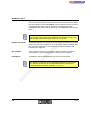
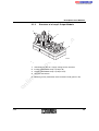
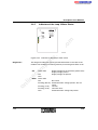
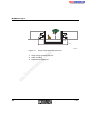
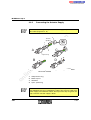
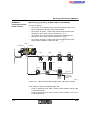
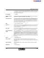
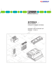
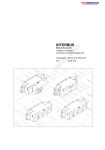
Figure 1-2
1-12
Schematic structure example of a Loop 2 system
5796C
Integration of Loop 2 Into the INTERBUS System
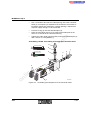
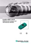
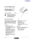
Figure 1-2 shows Loop 2 modules for different tasks within a system.
Loop 2 bus terminal module
2
Analog output module with one output
3
Analog input module with two inputs
4
Loop 2 module with four digital inputs
5
Loop 2 motor starter
6
Digital input and output module, each with two channels
7
Digital input module with four inputs
8
Digital input module with eight inputs
9
Digital output module with four outputs
m
1
co
Key:
on
l
in
ec
om
po
ne
nt
s.
10 Inline station with a Loop 2 branch terminal
5796C
1-13
INTERBUS Loop 2
1.2.4
Loop 2 Product Description
Modules with digital and analog inputs and outputs, a temperature
measurement module and a motor starter (e.g., to switch three-phase
induction motors directly) are available within the Loop 2 product range.
Versions
All of the modules and the bus terminal module have IP 65/IP 67 protection
whereas the Loop 2 motor starter has IP 54 protection.
s.
The following modules are available:
Bus terminal modules for connecting the Loop 2 system to the
INTERBUS remote bus
–
Loop 2 branch terminal (branch from the Inline system)
–
Module with four digital inputs
–
Module with eight digital inputs
–
Module with four digital outputs
–
Module with two digital inputs and two digital outputs
–
Power module with four digital inputs
–
Module with two analog inputs
–
Module with one analog output (current)
om
po
ne
nt
–
in
ec
on
l
System
requirements
co
m
I/O devices and supply are connected using the QUICKON insulation
displacement method. The Loop 2 modules are connected to INTERBUS
using a bus terminal module. Up to 63 bus devices can be connected to this
bus terminal module.
–
Module with one analog output (voltage)
–
Analog module for two temperature sensors
–
4-channel motor starter
The INTERBUS system with a controller board with firmware version
4.40 (G4) or later must be used to ensure optimum use of all system and
diagnostic functions.
For configuration, parameterization, and visualization of the system, CMD
software version 4.40 or later is available for standard controller boards.
When using a Field Controller, PC WORX software version 2.x or later is
available.
1-14
5796C
Integration of Loop 2 Into the INTERBUS System
Positioning
Loop 2 modules with IP 65/IP 67 protection are designed for applications
in the field. These modules can be directly used on machines or in systems.
Mounting
Loop 2 modules are directly screwed on a suitable (even) grounded
mounting surface. In this way, the functional earth ground is connected.
I/O connection
The inputs/outputs of sensors/actuators are connected to the I/O modules
using 5-pos. M12 connectors.
An INTERBUS Loop 2 system is connected to the INTERBUS remote bus
using a bus terminal module. This connection can made using SAB
connector hoods or the Loop 2 branch terminal from an Inline system.
nt
Bus connection
s.
co
m
Digital sensors can be connected using the 4-wire connection method
(signal, US, 0 V, functional earth ground). Digital actuators can be
connected using the 3-wire connection method (signal, 0 V, functional
earth ground).
om
po
ne
The bus terminal module adapts the bus signal to the Loop 2 system and
sends the adapted data to the connected modules via a Loop cable. The
Loop cable is connected using the QUICKON connection method
(insulation displacement).
on
l
in
ec
For additional information on the connection, please refer to the individual sections.
5796C
1-15
INTERBUS Loop 2
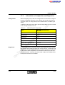
1.2.5
System Specifications
Table 1-1
INTERBUS Loop 2 system specifications
INTERBUS Loop 2 System Specifications
200 m (656.17 ft.)
Minimum distance between
0.2 m (0.66 ft.)
Bus terminal module and first module
-
Two modules
-
Last module and bus terminal module
s.
Maximum distance between
co
-
m
Permitted total length of the Loop 2
Bus terminal module and first module
-
Two modules
-
Last module and bus terminal module
ne
nt
-
po
Max. number of Loop 2 modules
Maximum current carrying capacity of the Loop 2
system
om
20 m (65.62 ft.)
1.8 A
19.2 V
in
ec
Minimum voltage at the device
63
on
l
The permissible number of devices that can be connected depends on
the specific station structure. None of the above mentioned limit parameters may be exceeded.
The number of modules that can be connected to a bus terminal module
depends on the current consumption of the modules. The maximum
current carrying capacity of the bus terminal module (1.8 A) must not be
exceeded.
Observe the voltage drops in the system. For safe bus operation, 19.2 V
(including ripple) must be available as supply to each module (see "Measuring Voltage Drop"on page 4-51).
To ensure the 19.2 V, voltage can be re-injected into a Loop 2 system via
the power module (IB L2 BOX 24 PWR IN DI 4/4 M12).
1-16
5796C
Integration of Loop 2 Into the INTERBUS System
1.3
INTERBUS S-Line as Part of the INTERBUS
Loop System
m
The INTERBUS S-Line modules have been designed for special operating
conditions in the field of mechanical engineering. They are especially
suitable if signals are to be processed when only little space is available,
and under extreme ambient conditions.
The INTERBUS S-Line modules are always integrated in INTERBUS
Loop 2. There are two possibilities:
s.
Bus connection
co
The small housings of the INTERBUS S-Line modules have IP 65/IP 67
protection. The sensors and actuators are connected via M8 connectors.
In this way the modules can be directly used in the machine.
ne
nt
1. Bus connection as branch line
A twin box is integrated in the INTERBUS Loop ring using the
QUICKON connection method. Up to two S-Line modules can be
connected to this twin box using M12 connectors (see page 1-19).
om
po
2. Bus connection as ring system
From the Loop 2 branch terminal in an Inline system, the bus structure
is established as ring system using Loop 2 M12 cables (see
page 1-20). Green Y connectors or ADAP boxes are installed in this
ring. To these the S-Line modules are connected using M12
connectors.
on
l
Safety circuit
in
ec
The bus is always connected to the S-Line modules using M12 connectors.
This is why the system is also referred to as INTERBUS Loop 2 M12.
5796C
A safety circuit can be integrated into the Loop 2 system. The signals of this
circuit are processed further using an Inline safety terminal. A yellow Y
connector is inserted in the ring to which an emergency stop button for
example can be connected (see page 1-22).
1-17
INTERBUS Loop 2
1.3.1
S-Line Product Description
Modules with up to eight digital inputs and outputs are available within the
S-Line product range.
The S-Line modules are integrated into INTERBUS Loop 2 using a branch
line (twin box) or a ring line (Y connector, ADAP boxes).
m
The following modules are available:
Module with eight digital inputs
–
Module with eight digital outputs
–
Module with four digital outputs, each with a load capacity of 2 A
–
Module with four digital inputs and four digital outputs
–
Module with four illuminated pushbuttons
s.
co
–
nt
Versions
S-Line has the same system requirements as Loop 2 (see page 1-14). The
basic system specifications are also the same as for Loop 2
(see page 1-16).
Positioning
S-Line modules with IP 67 protection are designed for applications in the
field. These modules can be directly used on machines or in systems.
Mounting
S-Line modules can either be screwed directly on a suitable even grounded
mounting surface or on suitable machine profiles. This can be carried out
from the front or from the side. Suitable screws and hammer slots are
available as an accessory.
po
om
in
ec
I/O connection
ne
System
requirements
on
l
Bus connection
1-18
The inputs/outputs of sensors/actuators are connected to the I/O modules
using 3-pos. M8 connectors.
The bus is connected to the S-Line modules using preassembled bus
cables with M12 connectors. The S-Line modules can be connected to
INTERBUS Loop 2 using a twin box (branch line) or green Y connectors or
ADAP boxes (ring system).
5796C
Integration of Loop 2 Into the INTERBUS System
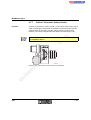
1.3.2
S-Line Example Topology
Bus Connection as Branch Line
R D Y
R U N
R D Y
F A IL
P F
S T O P
L
R C
B A
E
L D
R D
U
2
S L
IN
T E R
B
U S
0 2
0 1
a
IN
O U T
0 2
0 1
IN
O U T
U S
T E R
B
U S
X 3 1
IN T E R B U S
L O O P O U T
M 1
M 2
M 3
M 4
M
3
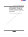
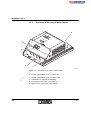
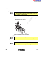
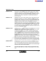
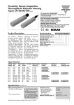
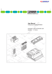
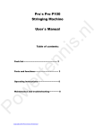
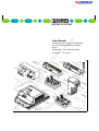
Example topology with a twin box (branch line)
1
Loop 2 bus terminal module
2
Loop 2 module
3
Twin box
4
S-Line module
5
Loop 2 motor starter/frequency inverter
6
Loop 2 encoder
5 7 9 6 B 1 0 5
om
Figure 1-3
po
ne
nt
4
in
ec
Key:
IN
X 3 0
IN T E R B U S
L O O P IN
D IA G
3
s.
b
6
5
m
U
co
1
on
l
The twin box is used to integrate one or two S-Line modules into a Loop 2
system (detailed description see page 2-18).
Unused twin box connections must be closed with a short-circuit connector
The twin box is not a bus device. It is important that it is not considered
as such for configuration and diagnostics.
5796C
1-19
INTERBUS Loop 2
In the example, the incoming bus cable of module 4 extends as far as
module 2, including the twin box and cable sections a and b. An error in the
incoming bus of module 4 could therefore also be in the forward line
(INTERBUS IN) between module 2 and the twin box (a).
Bus Connection as Ring System
B A
R D
R C
T R
U L
U S
D
1
2
1
1
2
U L
1
2
D
1
D
1
2
2
2
U M
E
U M
1
1
2
1
2
2
U S
D O 8
S A F E IL 1
L 2
1
D I8
2
S 1 1
S 1 2
S 2 1
S 2 2
S 4 1
S 4 2
S 5 1
S 5 2
1
S 4 1
S 4 2
S 1 1
S 1 2
S 2 1
S 2 2
S 3 3
S 3 4
2
S 3 3
S 3 4
1 3
1 3
1 4
1 4
m
1
1 3
1 4
4
ne
nt
3
s.
co
2
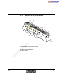
Figure 1-4
1
Example topology of a Loop 2 M12 ring system
Inline station
on
l
in
ec
Key:
5 7 9 6 B 1 0 6
om
po
5
2
Loop 2 branch terminal
3
Green Y connector
4
ADAP box
5
S-Line module
In the Loop 2 M12 ring system, each bus device that is to be connected is
assigned a green Y connector or a ADAP box, which leads the IN and OUT
line of the Loop 2 into the branch. See "Green Y Connector (Bus
Connection)"on page 2-21 or "ADAP Box (Bus Connection)"on page 2-24
for a detailed description.
Y connectors and ADAP boxes are not bus devices. It is important that
they are not considered as such for configuration and diagnostics.
1-20
5796C
Integration of Loop 2 Into the INTERBUS System
If, for example, an error is indicated on the outgoing bus cable of a module,
the error may have occurred at the following places:
At the connection between the module and the Y connector or the
module and the ADAP box
–
In the forward line to the next Y connector or to the ADAP box
(INTERBUS IN)
–
At this Y connector or this ADAP box
–
At the connection of this Y connector/this ADAP box to the next module
m
–
s.
co
The Y connector can be connected to the relevant Loop 2 module by a
Loop 2 M12 cable or by directly inserting the Y connector on the module.
on
l
in
ec
om
po
ne
nt
If the module is used in an environment with high levels of mechanical
strain, it should not be connected to the bus by directly inserting the Y
connector, but using a standard Loop 2 M12 cable.
5796C
1-21
INTERBUS Loop 2
Loop 2 Ring System with Safety Circuit
1
2
B A
R D
R C
T R
U L
U S
D
1
1
2
1
2
D
1
2
2
3
U L
1
E
U M
E
D
D
1
2
U M
1
2
1
2
1
2
2
U S
P W
D O 8
R
IN
L 2
S A F E IL 1
1
D I8
1
2
S 1 1
S 1 2
S 2 1
S 2 2
S 4 1
S 4 2
S 5 1
S 5 2
S 4 1
S 4 2
S 1 1
S 1 2
S 2 1
S 2 2
S 3 3
S 3 4
2
S 3 3
S 3 4
1 3
1 3
1 4
1 4
1 3
6
ne
po
4
nt
s.
co
m
1 4
7
om
5
on
l
Key:
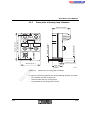
Example topology of a Loop 2 system with safety circuit
in
ec
Figure 1-5
6 1 6 3 A 0 1 0
1
Inline bus terminal
2
Loop 2 branch terminal
3
Inline safety terminal
4
Green Y connector for bus tap
5
Digital input module
6
Yellow Y connector for safety circuit tap
7
Emergency stop button
A safety circuit is created using the two additional cables (brown and
white), which are present in the Loop 2 M12 cable. These cables can be
tapped via a yellow Y connector (6). The safety circuit signals can then be
processed further via an Inline safety terminal (3).
1-22
5796C
Section 2
This section informs you about
–
the INTERBUS Loop 2 product gorups
–
the INTERBUS S-Line product groups
Product Groups.....................................................................................................2-3
Loop 2 Bus Terminal Module .....................................................2-3
2.2
Loop 2 Branch Terminal..............................................................2-6
2.3
Digital Loop 2 Devices ................................................................2-7
2.4
Analog Loop 2 Devices ...............................................................2-9
2.5
Loop 2 Motor Starter .................................................................2-12
2.6
Loop 2 Power Module ...............................................................2-14
2.7
INTERBUS S-Line.....................................................................2-15
nt
s.
co
m
2.1
Product Range .............................................................2-15
2.7.2
Digital S-Line Modules .................................................2-15
2.7.3
Information on Configuration and Diagnostics .............2-17
2.7.5
Twin Box (Bus Connection) .........................................2-18
Green Y Connector (Bus Connection) .........................2-21
ADAP Box (Bus Connection) .......................................2-24
om
2.7.6
po
2.7.4
ne
2.7.1
Yellow Y Connector (Safety Circuit).............................2-26
2.7.8
M8 Y Connector (Actuator Supply) ..............................2-29
on
l
in
ec
2.7.7
5796C
2-1
2-2
5796C
s.
nt
ne
po
om
in
ec
on
l
co
m
Product Groups
2
Product Groups
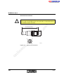
2.1
Loop 2 Bus Terminal Module
IBS L2 IP 24 BK-T bus terminal module
For the housing dimensions, please refer to Figure 3-1 on page 3-3.
on
l
in
ec
Housing
Function
5 7 9 6 B 2 0 1
om
Figure 2-1
po
ne
nt
s.
co
m
A Loop 2 bus terminal module is available for the INTERBUS Loop 2
system, with which the INTERBUS Loop 2 is directly connected to the
INTERBUS remote bus or the INTERBUS installation remote bus.
The bus terminal module forms the head of a Loop 2 system. It connects
the modules of a Loop 2 system to the INTERBUS remote bus and
performs the required bus signal conditioning.
The bus terminal generates the communications voltage for the connected
devices from the supply voltage. It also provides the supply of the
connected analog modules and the sensor supply of the digital input
modules.
The bus terminal module also allows you to disconnect or reconnect the
Loop 2 system from or to the network using the application software.
5796C
2-3
INTERBUS Loop 2
The following cables can be connected to the bus terminal module:
–
Incoming and outgoing INTERBUS remote bus
INTERBUS is connected using SAB connector hoods.
–
Incoming and outgoing installation remote bus. In the installation
remote bus, the supply for the bus logic and I/O is provided.
INTERBUS is connected using SAB connector hoods.
–
Incoming and outgoing INTERBUS Loop 2.
INTERBUS Loop 2 is connected using the QUICKON connection
method.
co
m
Connections
The bus terminal module supplies communications voltage to the module
electronics of the connected modules. If this supply voltage is switched off,
the bus stops.
ne
Voltage supply of the
bus terminal module
nt
s.
Digital actuators must be supplied separately at the corresponding
module.
om
po
The voltage supply of the actuators should be installed and protected
independently of the voltage supply of the INTERBUS module electronics.
In this way INTERBUS continues to run even if some I/O devices have
been switched off (see also "Power Concept"on page 4-9).
on
l
in
ec
When using an emergency stop circuit, only the voltage supply of the
actuators may be connected to the emergency stop circuit. Errors can then
be detected with the sensors in the emergency stop state.
2-4
For the operation of INTERBUS Loop 2 with "maximum structure" (up to 63
Loop 2 devices at a maximum current carrying capacity of 1.8 A) it is
possible to re-inject the supply voltage for INTERBUS Loop 2 in the field.
See "Loop 2 Power Module"on page 2-14 and "Power Concept"on
page 4-9.
The communications voltage of the devices depends on the supply voltage of the bus terminal module. It is therefore useful to supply the bus
terminal module with an increased voltage (28.5 V).
5796C
Product Groups
The number of devices that you can connect to a bus terminal module is
determined by several parameters:
–
The maximum number of devices in INTERBUS is limited to 512.
–
A maximum of 254 remote bus devices may be connected in
INTERBUS.
–
Up to 63 modules (local bus devices) can be connected to a Loop 2 bus
terminal module
This number includes all devices after the bus terminal module.
If the Loop 2 system is integrated in an Inline station via a Loop 2
branch terminal, the device number includes both the Inline terminals
of the station and the modules of Loop 2.
The devices of a remote bus branch connected to the Inline station do
not affect the number of Loop 2 system or Inline station devices.
–
The bus terminal module can supply a maximum current of 1.8 A in the
logic area.
Therefore please note the logic current consumption and the sensor
currents of every device when configuring a Loop 2 system (or an Inline
station with an integrated Loop 2). This data is given in every modulespecific data sheet. The current consumption can be different
depending on the module.
po
ne
nt
s.
co
m
Number of devices
om
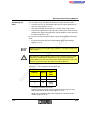
Do Not Exceed the Limit Parameters!
LEDs
on
l
Protection
in
ec
The permissible number of devices that can be connected depends on
the specific station structure. None of the above mentioned limit parameters may be exceeded.
Functional earth
ground
5796C
The bus terminal module has short circuit protection through an electronic
fuse.
The diagnostic indicators of the bus terminal module indicate the Loop 2
state and the remote bus state, and indicate if the supply voltages are
present or not (see "Bus Terminal Module Indicators"on page 3-18).
When mounting the module on a grounded mounting surface the module
is grounded through the mounting screws (see "Structure of the Loop 2 Bus
Terminal Module"on page 3-3 and Section "Grounding Concept" on
page 4-11).
2-5
INTERBUS Loop 2
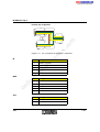
2.2
Loop 2 Branch Terminal
Via a Loop 2 branch terminal, you can integrate a Loop 2 branch and its
modules into an INTERBUS Inline station.
nt
s.
co
m
The Loop 2 branch terminal converts INTERBUS signals to the bus physics
of Loop 2 and provides the supply voltage.
Loop 2 branch terminal IB IL 24 L2
po
Figure 2-2
ne
5 5 5 2 1 0 0 1
in
ec
om
Phoenix Contact recommends to supply INTERBUS Loop 2 via a separate power terminal. For additional information on the terminal, please
refer to the module-specific data sheet.
on
l
If an increased voltage (28.5 V) is provided for the power terminal this
voltage is also available in the Loop 2 system.
The Loop 2 branch terminal is not a device with protocol chip in the
INTERBUS system. This branch terminal has no logical and physical device number. This must be considered during error diagnostics if two or
more branch terminals are installed side by side.
If the Loop 2 system is integrated in an Inline station via a Loop 2 branch
terminal, the local bus devices are also counted. Please take into
account that a maximum of 63 devices can be connected to a bus
terminal module (remote bus devices).
2-6
5796C
Product Groups
2.3
Digital Loop 2 Devices
The following modules are available:
Digital input modules with four inputs
–
Digital input modules with eight inputs
–
Digital output modules with four outputs
–
Digital input/output modules with two inputs and two outputs
m
–
The size of the module housing varies according to the number of
connections.
2
5 7 9 6 0 2 0 2
Digital modules
om
Figure2-3
po
ne
nt
s.
1
co
Housing
Housing of the output modules and of the input and output modules
2
Housing of the input modules
in
ec
1
For the housing dimensions, please refer to the figures on page 3-8.
on
l
Function
5796C
Digital output modules are used to network individual actuators, and digital
input modules are used to read individual sensors. Individual actuators and
individual sensors can be distributed on machines or in systems.
2-7
INTERBUS Loop 2
Input module
connections
Using the input modules the incoming and outgoing INTERBUS Loop 2
and the I/O devices (sensors) are connected.
The INTERBUS Loop 2 cables are connected using the QUICKON
connection method. The sensors are connected via M12 circular
connectors.
Using the output modules the incoming and outgoing INTERBUS Loop 2,
the I/O devices (actuators) and the supply of the actuators are connected.
m
Output module
connections
co
The INTERBUS Loop 2 cables and the supply lines for the actuators are
connected with the QUICKON connection method. The actuators are
connected via M12 circular connectors.
Protection against polarity reversal is carried out internally via a bridge
rectifier.
LEDs
The diagnostic and status indicators on the modules provide information on
the bus and on the status of the inputs and outputs (see Section 3.4.2 on
page 3-20).
Functional earth
ground
When mounting the module on a grounded mounting plate the module is
grounded through the mounting screws.
po
ne
nt
s.
Protection of Loop 2
The communications voltage is provided when connecting the supply
voltages to the bus terminal module. The input modules are also supplied
with the voltage supply for the sensors. Using the output modules the
actuator supply must be supplied via additional supply lines.
on
l
in
ec
Provision of the
supply
om
Voltage Supply for the Digital I/O Modules
Please note that bus supply and actuator supply should be electrically
isolated (see also "Power Concept"on page 4-9).
To guarantee error-free bus operation always ensure actuator supply
and bus supply are isolated.
2-8
5796C
Product Groups
2.4
Analog Loop 2 Devices
The following modules are available:
Analog input module with two inputs
–
Output module with one current output
–
Output module with one voltage output
–
Analog module for two temperature sensors
m
–
All analog Loop 2 modules are of the same size.
po
ne
nt
s.
co
Housing
5 7 9 6 A 2 0 3
Example of an analog Loop 2 module
om
Figure2-4
For the housing dimensions, please refer to Figure 3-9 on page 3-11.
Using the input modules the incoming and outgoing INTERBUS Loop 2
and the I/O devices (sensors) are connected.
in
ec
on
l
Input module
connections
Output module
connections
The INTERBUS Loop 2 cables are connected using the QUICKON
connection method. The sensors are connected via M12 circular
connectors.
Using the output modules the incoming and outgoing INTERBUS Loop 2
and the I/O devices (actuators) are connected.
The INTERBUS Loop 2 cables are connected using the QUICKON
connection method. The actuators are connected via M12 circular
connectors.
Protection of Loop 2
5796C
Protection against polarity reversal is carried out internally via a bridge
rectifier.
2-9
INTERBUS Loop 2
LEDs
The module diagnostic indicators provide information on the bus (see
"Indicators for Analog I/O Modules"on page 3-22).
Shielding
Shielding of analog input modules is carried out via the
IB L2 SHIELD shield plate supplied with the module.
co
m
Phoenix Contact only recommends connecting the shield via the
IB L2 SHIELD shield plate for analog output modules in the case of extreme interference. The shield plate can be ordered as an accessory
("Ordering Data for Loop 2 Accessories"on page 7-4).
When mounting the module on a grounded mounting plate the module is
grounded through the mounting screws. If the module cannot be fixed to a
grounded mounting plate, use the IB L2 SHIELD shield plate for analog
output modules. Connect the shield plate using a separate cable with a
grounding point.
Parameterization
Analog input modules are parameterized via the INTERBUS OUT process
data word (output data word).
po
ne
nt
s.
Functional earth
ground
Analog output modules are parameterized using the connector coding.
in
ec
om
Some output modules can also be parameterized to other configurations
through the output data words. Refer to the module-specific data sheet to
find out if a specific analog module can be configured and how the output
data words are assigned.
Diagnostics in the
input data word
Error detection is implemented via the input data word (process data).
Analog input modules have overrange recognition in all measuring ranges.
on
l
Open circuit is indicated in the 4 mA to 20 mA range.
2-10
Open circuit can also be indicated for modules used to connect
thermocouples (for module-specific data, please refer to the appropriate
data sheets).
5796C
Product Groups
Extended
diagnostics
Some data formats support extended diagnostics. If extended diagnostics
are available for a specific module, it is indicated in the module-specific
data sheet.
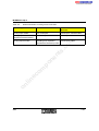
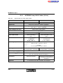
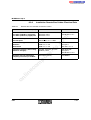
Possible error messages are listed in Table 2-1.
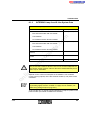
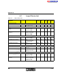
Table 2-1
Error messages for analog input modules
Error
8001
Under range
8002
Open circuit
8004
Measured value invalid
8008
Cold junction defective
8010
Configuration invalid
8020
Supply voltage defective
8040
Module faulty
8080
Overrange
po
ne
nt
s.
co
m
Code (hex)
All required supply voltages (communications voltage, sensor supply and
actuator supply) are provided when connecting the supply voltages to the
bus terminal module.
in
ec
Provision of the
supply
om
Voltage Supply for Analog Input and Output Modules
on
l
An electrically isolated I/O supply is generated from the supply voltage of
the bus terminal module.
5796C
2-11
INTERBUS Loop 2
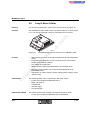
2.5
Loop 2 Motor Starter
For the housing dimensions, please refer to Figure 3-10 on page 3-12.
Function
The INTERBUS Loop 2 motor starter can operate either as a direct starter
or as a reversing-load motor starter in electromechanical versions.
nt
s.
co
m
Housing
Direct starting for four or reversing-load operation for two independent
motors
–
Integrated motor protection for each motor by means of thermistor
current or thermostatic switches
–
Line voltage up to 500 V AC
–
Motors can be switched off independently at overtemperature
om
ne
–
on
l
in
ec
Features
INTERBUS Loop 2 motor starter IB L2 IP 500 MLR 4-6A
po
5 7 9 6 0 2 0 4
Figure 2-5
Connections
Connection method
–
Actuators (power section) can be deactivated independently of
INTERBUS Loop 2.
–
Connectors for supply voltage, actuator voltage (power supply), motor
and PTC input
The following cables can be connected to the motor starter:
–
Incoming and outgoing INTERBUS Loop 2
–
Motor 1 to motor 4
–
4 thermistors
–
Actuator supply
–
Line input/output
The following connection methods are used for the motor starter:
–
2-12
Incoming and outgoing INTERBUS Loop 2 (QUICKON)
5796C
Product Groups
–
Motor 1 to motor 4 (POWER-COMBICON)
–
Four thermistors (MINI-COMBICON)
–
Actuator supply (POWER-COMBICON)
–
Line input/output (POWER-COMBICON)
co
The communications voltage for the motor starter is provided via the
Loop 2 cable. The PTC detectors (thermistors) and the actuators (power
section) are supplied with power by means of a 24 V connection (actuator
supply).
s.
Provision of the
supply
m
The connector pin assignment of the MINI and POWER COMBICON
connectors is specified in the module-specific data sheet.
nt
The motor starter is also connected to a 3-phase system supply.
ne
Protection
The diagnostic and status indicators on the module provide information on
the bus and on the status of the connected device (see "Indicators of the
Loop 2 Motor Starter"on page 3-23).
on
l
LEDs
Grounding
5796C
Protection against polarity reversal is carried out internally via a bridge
rectifier.
in
ec
Protection of Loop 2
om
po
The motor starter does not have any built-in protection. The short-circuit
protection according to IEC 60947 must be implemented in a separate
device.
For additional information, please refer to the module-specific data
sheet.
The motor starter is connected to the flange via the PE connection
(protective earth ground).
2-13
INTERBUS Loop 2
2.6
Loop 2 Power Module
For the housing dimensions, please refer to Figure 3-7 on page 3-9.
Function
The Loop 2 power module is used to re-inject the supply voltage in the
Loop 2 system if the maximum total current of 1.8 A is reached. The
module can also be used as an input module with four digital inputs.
nt
s.
co
m
Housing
ne
5 7 9 6 A 2 0 5
INTERBUSLoop 2 power module
po
Figure 2-6
The incoming and outgoing INTERBUS Loop 2, the input devices (sensors)
and the power for supplying the modules are connected at the power
module. (The voltage is supplied opposite the data direction and the
module counting method.)
Connection method
The INTERBUS Loop 2 cables and the supply lines are connected using
the QUICKON connection method. The sensors are connected via M12
circular connectors.
in
ec
om
Connections
on
l
Protection of Loop 2
Protection against polarity reversal is carried out internally via a serial
diode.
To guarantee error-free bus operation always ensure that both actuator
supply and bus supply are protected independently.
LEDs
The diagnostic and status indicators on the modules provide information on
the bus and on the status of the inputs and power supply (see "Indicators
of Digital I/O Modules"on page 3-20).
Functional earth
ground
When mounting the module on a grounded mounting plate the module is
grounded through the mounting screws.
2-14
5796C
Product Groups
2.7
2.7.1
INTERBUS S-Line
Product Range
m
For detailed description, please refer to "INTERBUS S-Line as Part of
the INTERBUS Loop System"on page 1-17.
Digital S-Line Modules
ne
2.7.2
nt
s.
co
The INTERBUS S-Line modules can be integrated in INTERBUS Loop 2.
They can especially be used when only little space is available on the
machine.
The following modules are available:
on
l
Connections
–
Module with eight digital outputs
–
Module with four digital outputs, each with a load capacity of 2 A
–
Module with four digital inputs and four digital outputs
–
Module with four illuminated pushbuttons
om
po
Module with eight digital inputs
For the housing dimensions, please refer to "Dimensions of the S-Line
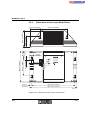
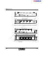
Modules"on page 3-13.
in
ec
Housing
–
INTERBUS Loop 2 is connected to these modules using M12 connectors.
The incoming and the outgoing bus is connected to these M12 connectors.
In order to integrate the S-Line modules in a Loop 2 system an
intermediate station (twin box, see page 2-18) is necessary to adapt
Loop 2 to Loop 2 M12.
From a Loop 2 branch terminal the S-Line modules can also be operated
via Loop 2 M12 cables only. For this an intermediate station (Y connector,
see page 2-21, or ADAP box, see page 2-24) is also required.
The digital output module with four outputs
(IB L2-M BOX 24 DO 4/4 M8-2A) provides a M12 connection for the
actuator supply. For the other modules with outputs the actuator supply can
5796C
2-15
INTERBUS Loop 2
be connected to any output. If you want to use all outputs, you must install
an M8 Y connector (see page 2-29). This connector enables the
connection of the actuator supply and the output.
The sensors and actuators are connected via 3-pos. M8 connectors.
The module diagnostic indicators (green) provide information on the states
of the bus and communications voltage. Output modules additionally
provide a diagnostic indicator for the actuator supply.
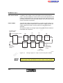
m
LEDs
s.
Functional earth grounding on the S-Line modules is not required.
on
l
in
ec
om
po
ne
nt
Functional earth
ground
co
The status indicators (yellow) provide information on the states of the
inputs and outputs (see "Indicators of the S-Line Modules"on page 3-25).
2-16
5796C
Product Groups
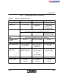
2.7.3
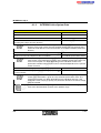
Configuration
Information on Configuration and Diagnostics
When configuring Loop 2 M12, the configuration of a branch line or ring line
must be considered separately. As the branch line contains the forward
and return path, the voltage drop must be doubled when considering the
sizing.
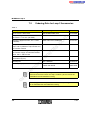
Determining the voltage drop
co
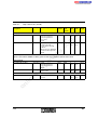
Table 2-2
Assumed Voltage Drop
per Item
Twin box
0.1 V
nt
s.
Item
0.1 V
ADAP box
Loop 2 M12 module
ne
Y connector
0.1 V
0.1 V
0.1 V/m
Loop 2 M12 cable (branch)
0.2 V/m
om
po
Loop 2 M12 cable (ring)
Loop 2 cable
0.03 V/m
As with configuration, it must be noted for error diagnostics that a branch
line contains the forward and return path. As the twin box, Y connector and
ADAP boxes are not INTERBUS devices, the error source may not only be
on the path to these components, but could be anywhere up to the next
INTERBUS device. Therefore we recommend using preassembled cables
to keep error sources to a minimum.
on
l
in
ec
Diagnostics
m
To determine the total voltage drop, specific voltage drops can be assumed
at an average current of 1.25 A.
5796C
2-17
INTERBUS Loop 2
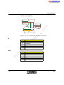
2.7.4
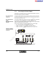
Twin Box (Bus Connection)
For the housing dimensions, please refer to Figure 3-14 on page 3-15.
Function
The twin box is used to connect S-Line modules to INTERBUS Loop 2. The
twin box is integrated in Loop 2 using the QUICKON connection method
and enables the connection of two S-Line modules via M12 female
connectors (see "Bus Connection as Branch Line"on page 1-19). For this
you need a special 4-wire Loop 2 M12 cable (see "Assembling Loop 2 M12
Cables"on page 4-43).
co
m
Housing
ne
nt
s.
Unused M12 female connectors must be closed with a short-circuit connector (SAC-4P-M12MS L2 SCP). Bus operation is not possible with an
unused M12 female connector.(see "Short-Circuit Connector"on
page 2-20).
po
The twin box does not contain any active components, i.e., it is not an
INTERBUS device.
in
ec
om
Connections
1
2
0 2
0 1
1
IN
O U T
2
3
2
on
l
5
2-18
4
3
1
5
4
6 4 8 0 A 0 0 8
Figure 2-7
Pin assignments of the twin box
5796C
Product Groups
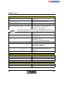
Loop 2 connection
Connection
Signal
1
INTERBUS Loop 2 OUT
2
INTERBUS Loop 2 IN
Loop 2 connection 1
2
OUT-
3
IN-
4
OUT+
5
-
co
IN+
s.
1
m
Assignment
nt
Pin
Loop 2 connection 2
Assignment
IN+
2
OUT-
3
IN-
4
OUT+
om
-
on
l
in
ec
5
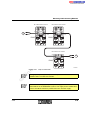
Internal circuit
diagram
po
1
ne
Pin
0 2
0 1
IN
O U T
2
2
2
1
2
6 1 6 3 B 0 1 4
Figure 2-8
5796C
Circuit diagram of the twin box
2-19
INTERBUS Loop 2
Short-Circuit Connector
(1 .6 1 4 ")
ne
Æ
nt
s.
1 4 .7 m m
(Æ 0 .5 7 9 ")
co
4 1 m m
m
Unused M12 female connectors must be closed with a short-circuit connector (SAC-4P-M12MS L2 SCP). Bus operation is not possible with an
unused M12 female connector.
3
po
4
om
1
6 1 6 3 A 0 1 6
Short-circuit connector
on
l
in
ec
Figure 2-9
2
2-20
5796C
Product Groups
2.7.5
Function
Green Y Connector (Bus Connection)
The green Y connector is used to connect one S-Line module to
Loop 2 M12 (see "Bus Connection as Ring System"on page 1-20).
co
m
If the module is used in an environment with high levels of mechanical
strain, it should not be connected to the bus by directly inserting the Y
connector into the S-Line module, but using a standard Loop 2 M12 cable.
ne
M O D
6 4 8 0 A 0 0 9
Connections of the green Y connector
on
l
Figure 2-10
O U T
in
ec
om
po
IN
nt
s.
The Y connector does not contain any active components, i.e., it is not
an INTERBUS device.
5796C
2-21
INTERBUS Loop 2
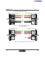
Internal pin assignment
1
2
3
4
5
IN
1
2
3
4
1
m
5
M O D
2
3
co
4
5
s.
O U T
6 1 6 3 B 0 1 8
nt
Pin assignment of the green Y connector
ne
Figure 2-11
IN
Pin
Assignment
Safety circuit IN
2
Loop IN-
3
Multi-function circuit IN
4
Loop IN+
5
Parallel cable
MOD
in
ec
om
po
1
on
l
Pin
Assignment
1
Loop IN+
2
Loop OUT-
3
Loop IN-
4
Loop OUT+
5
Multi-function circuit OUT
OUT
Pin
2-22
Assignment
1
Safety circuit OUT
2
Loop OUT-
5796C
Product Groups
Pin
Assignment
Multi-function circuit OUT
4
Loop OUT+
5
Parallel cable
on
l
in
ec
om
po
ne
nt
s.
co
m
3
5796C
2-23
INTERBUS Loop 2
2.7.6
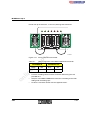
ADAP Box (Bus Connection)
For the housing dimensions, please refer to Figure 3-11 on page 3-13. The
dimensions are the same as for the S-Line module with eight connections.
Function
The green ADAP box is used to connect up to three S-Line modules to
Loop 2 M12 (see Figure 1-4 on page 1-20).
m
Housing
nt
s.
co
Unused M12 female connectors must be closed with a short-circuit connector (SAC-4P-M12MS L2 SCP). Bus operation is not possible with an
unused M12 female connector (see "Short-Circuit Connector"on
page 2-20).
ne
The ADAP box does not contain any active components, i.e., it is not an
INTERBUS device.
om
po
Connections
in
ec
3
2
3
2
3
2
on
l
4
2-24
B U S IN
Figure 2-12
1
1
4
M O D U L E 1 2 3
4
1
B U S O U T
5 7 9 6 B 2 0 2
Pin assignments of the ADAP box
5796C
Product Groups
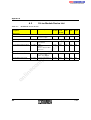
Loop 2 M12 (BUS IN)
2
IN-
3
OUT-
4
IN+
1
IN+
2
OUT-
3
IN-
4
OUT+
5
-
Pin
co
Assignment
s.
Pin
m
OUT+
ne
Loop 2-M12
(BUS OUT)
1
Assignment
po
Loop 2 M12
(Module
connections 1, 2 and
3)
Assignment
nt
Pin
IN+
2
OUT-
om
1
IN-
4
OUT+
5
-
on
l
in
ec
3
5796C
2-25
INTERBUS Loop 2
2.7.7
A yellow Y connector is used to create a safety circuit in the Loop 2 ring to
which an emergency stop button for example can be connected. For this
parallel cables in the Loop 2 ring are further used by an Inline safety
terminal (see "Loop 2 Ring System with Safety Circuit"on page 1-22).
m
Function
Yellow Y Connector (Safety Circuit)
om
O U T
po
M O D
ne
nt
IN
s.
co
The Y connector does not contain any active components, i.e., it is not
an INTERBUS device.
Connections of the yellow Y connector
on
l
in
ec
Figure 2-13
6 4 8 0 A 0 0 9
2-26
5796C
Product Groups
Internal Pin Assignment
1
2
3
4
5
IN
1
2
5
1
M O D
co
2
m
3
4
3
4
s.
5
O U T
Pin assignment of the yellow Y connector
ne
Figure 2-14
nt
6 1 6 3 B 0 2 0
IN
Assignment
po
Pin
Safety circuit IN
2
Loop OUT-
om
1
5796C
Multi-function circuit IN
4
Loop OUT+
5
Parallel cable
Pin
Assignment
in
ec
on
l
MOD
3
1
Safety circuit IN
2
Safety circuit OUT
3
Multi-function circuit IN
4
Multi-function circuit OUT
5
Parallel cable
2-27
INTERBUS Loop 2
OUT
Pin
Assignment
Safety circuit OUT
2
Loop OUT-
3
Multi-function circuit OUT
4
Loop OUT+
5
Parallel cable
on
l
in
ec
om
po
ne
nt
s.
co
m
1
2-28
5796C
Product Groups
2.7.8
For modules with digital outputs without additional actuator supply
connection the actuator supply can be connected to any output. However,
if you want to use all outputs you can insert a M8 Y connector. The output
and actuator supply can be connected to this connector.
co
s.
nt
6 4 8 0 A 0 1 1
Connections of the black M8 Y connector
po
Figure 2-15
ne
1 6 9 6 2 2 2
D O U T
M o d u le
m
+ 2 4 V U s
Function
M8 Y Connector (Actuator Supply)
om
Internal Pin Assignment
+ 2 4 V U
1
on
l
in
ec
3
M o d u le
1
3
4
1
3
4
D
O U T
Figure 2-16
5796C
S
6 4 8 0 A 0 1 2
Pin assignment of the black M8 Y connector
2-29
INTERBUS Loop 2
D OUT
Pin
Assignment
1
24 V (US)
4
Output
3
0 V (US)
24 V (US)
4
Not used
3
0 V (US)
s.
1
co
Assignment
Module
Assignment
24 V (US)
4
Output
3
0 V (US)
on
l
in
ec
om
po
1
ne
Pin
nt
Pin
m
+24 V US
2-30
5796C
Section 3
This section informs you about
–
the module structure
–
the housing dimensions
–
the diagnostic and status indicators
Description of the Modules ...................................................................................3-3
Structure of a Loop 2 input Module................................3-4
3.1.3
Structure of a Loop 2 Output Module.............................3-5
3.1.4
Structure of the Loop 2 Motor Starter ............................3-6
3.1.5
Structure of an S-Line Module .......................................3-7
Dimensions of the Loop 2 Bus Terminal Module ...........3-8
3.2.2
Dimensions of Digital Loop 2 Modules...........................3-9
3.2.3
Dimensions of Analog Loop 2 Modules .......................3-11
Dimensions of the S-Line Modules ..............................3-13
Dimensions of the Twin Box ........................................3-15
Labeling of I/O Modules ............................................................3-16
Diagnostic and Status Indicators...............................................3-17
in
ec
on
l
Dimensions of the Loop 2 Motor Starter ......................3-12
om
3.2.6
5796C
s.
3.2.1
3.2.5
3.4
nt
Dimensions of the Modules.........................................................3-8
3.2.4
3.3
m
Structure of the Loop 2 Bus Terminal Module ...............3-3
3.1.2
co
3.1.1
ne
3.2
Structure of the modules .............................................................3-3
po
3.1
3.4.1
Bus Terminal Module Indicators ..................................3-18
3.4.2
Indicators of Digital I/O Modules ..................................3-20
3.4.3
Indicators of the Power Module ...................................3-21
3.4.4
Indicators for Analog I/O Modules................................3-22
3.4.5
Indicators of the Loop 2 Motor Starter .........................3-23
3.4.6
Indicators of the S-Line Modules .................................3-25
3-1
3-2
5796C
s.
nt
ne
po
om
in
ec
on
l
co
m
Description of the Modules
Description of the Modules
3.1
Structure of the modules
Structure of the Loop 2 Bus Terminal Module
3
2
U
L
R C
co
m
3.1.1
E
B A
L D
R D
L C
U
L 2
IN
0 2
IN T E R B U S O U T
0 3
0 4
IN T E R B U S L O O P 2 IN
IN T E R B U S L O O P 2 O U T
5 7 9 6 B 3 0 1
Structure of the IB L2 IP 24 BK-T bus terminal module
Mounting screw (connection to the functional earth ground - FE)
on
l
in
ec
1
U S
om
Figure 3-1
B
T y p e : IB L 2 IP 2 4 B K -T
O rd . N r.: 2 7 3 2 3 7 6
B u s T e r m in a l
2 4 V D C , IP 6 7
M o d u le Id e n t. : 4
po
1
T E R
nt
IN T E R B U S IN
ne
0 1
6
5
4
s.
3
5796C
2
Incoming remote bus or installation remote bus (INTERBUS IN)
3
Outgoing remote bus or installation remote bus (INTERBUS OUT)
4
Diagnostic LEDs
5
Incoming INTERBUS Loop 2 (Loop 2 IN)
6
Outgoing INTERBUS Loop 2 (Loop 2 OUT)
3-3
INTERBUS Loop 2
3.1.2
Structure of a Loop 2 input Module
1
m
2
co
3
5 7 9 6 A 3 0 2
Structure of a Loop 2 input module
om
Figure 3-2
po
ne
nt
s.
4
Incoming INTERBUS Loop 2 (Loop 2 IN)
2
Outgoing INTERBUS Loop 2 (Loop 2 OUT)
in
ec
1
Sensor connections
4
Mounting screw (connection to the functional earth ground - FE)
on
l
3
3-4
5796C
Description of the Modules
3.1.3
Structure of a Loop 2 Output Module
2
1
m
3
co
4
5 7 9 6 B 3 0 3
Structure of a Loop 2 output module
po
Figure 3-3
ne
nt
s.
5
Connections of the 24 V supply voltage for the actuators
2
Incoming INTERBUS Loop 2 (Loop 2 IN)
3
Outgoing INTERBUS Loop 2 (Loop 2 OUT)
4
Actuator connections
5
Mounting screw (connection to the functional earth ground - FE)
on
l
in
ec
om
1
5796C
3-5
INTERBUS Loop 2
3.1.4
Structure of the Loop 2 Motor Starter
m
5
s.
co
1
om
po
ne
nt
2
3
in
ec
4
on
l
Figure 3-4
3-6
5 7 9 6 0 3 0 4
Structure of the Loop 2 motor starter
1
Incoming INTERBUS Loop 2 (Loop 2 IN)
2
Outgoing INTERBUS Loop 2 (Loop 2 OUT)
3
Connection for equipotential bonding
4
Left terminal connection compartment
5
Right terminal connection compartment
5796C
Description of the Modules
3.1.5
Structure of an S-Line Module
1
m
2
nt
s.
co
3
Structure of an S-Line module (example)
INTERBUS Loop 2 M12 connection
in
ec
1
5 7 9 6 B 3 1 8
om
Figure 3-5
po
ne
4
Diagnostic LEDs
3
Digital inputs and outputs
4
Status LEDs
on
l
2
5796C
3-7
INTERBUS Loop 2
3.2
Dimensions of the Modules
The modules of the INTERBUS Loop 2 range have different housing sizes.
The following figures show the housing dimensions.
Dimensions of the Loop 2 Bus Terminal Module
(6 .4 1 7 ")
R C
L
B A
E
L D
L C
R D
U
L 2
co
(2 .0 4 7 ")
B
U
T E R
B
B
U S
om
9 m m
(0 .3 5 4 ")
8 .6 m m
(0 .3 3 9 ")
4 .8 m m
(0 .1 8 9 ")
1 0 m m
(0 .3 9 4 ")
S e c tio n a l v ie w B - B
5 7 m m
1 5 m m
(0 .5 9 1 ")
Æ
on
l
in
ec
9 3 m m (3 .6 6 1 ")
4 .0 m m (0 .1 5 8 ")
S e c tio n a l v ie w A - A
Æ
Æ
(6 .8 9 0 ")
(2 .2 4 4 ")
1 7 5 m m
po
A
ne
A
8 0 m m
nt
5 2 m m
s.
IN
(3 .1 5 0 ")
1 6 3 m m
m
3.2.1
Æ
6 m m
(0 .2 3 6 ")
5 7 9 6 B 3 0 7
Figure 3-6
3-8
Dimensions of the bus terminal module
5796C
Description of the Modules
m
co
s.
nt
(4 .5 1 6 ")
1 1 4 .7 m m
Dimensions of Digital Loop 2 Modules
om
po
ne
(4 .9 2 1 ")
1 2 5 m m
3.2.2
in
ec
6 2 m m
Figure 3-7
(2 .4 4 1 ")
6 0 m m
(2 .3 6 2 ")
5 7 9 6 0 3 0 8
Dimensions of digital Loop 2 modules
on
l
In Figure 3-7 the housing dimensions of the following modules are shown:
5796C
–
I/O module with two digital inputs and two digital outputs
–
Output module with four digital outputs
–
Power module with four digital inputs
3-9
INTERBUS Loop 2
0 2
0 1
m
(3 .3 3 5 ")
6 0 m m
(2 .3 6 2 ")
5 7 9 6 0 3 0 9
Dimensions of the digital input module
om
Figure 3-8
(2 .4 4 1 ")
po
6 2 m m
ne
nt
s.
co
8 4 .7 m m
9 5 m m
(3 .7 4 0 ")
IN
O U T
In Figure 3-8 the housing dimensions of the following modules are shown:
Input module with four digital inputs
–
Input module with eight digital inputs
on
l
in
ec
–
3-10
5796C
Description of the Modules
3.2.3
Dimensions of Analog Loop 2 Modules
6 0 m m
m
co
nt
(0 .3 1 5 ")
s.
(0 .1 6 9 ")
(3 .3 3 5 ")
3 .5 m m
(2 .4 4 ")
in
ec
6 2 m m
om
po
ne
8 m m
4 .3 m m
8 4 .7
9 5 m m
m m
(3 .7 4 0 ")
IN
O U T
(2 .3 6 2 ")
Figure 3-9
3 2 .0 m m
(1 .2 6 0 ")
(0 .1 3 8 ")
5 7 9 6 0 3 1 0
Dimensions of analog Loop 2 modules
on
l
In Figure 3-9 the housing dimensions of the following modules are shown:
5796C
–
Input module with two analog inputs
–
Output module with one analog output
–
Input module for two temperature sensors
3-11
INTERBUS Loop 2
3.2.4
co
m
(3 .5 0 4 ")
po
ne
nt
s.
8 9 m m
1 8 m m
(0 .7 0 9 ")
om
(0 .5 5 1 ")
9 m m
(0 .3 5 4 ")
in
ec
1 4 m m
(5 .6 6 9 ")
1 4 4 m m
(9 .9 2 1 ")
(8 .3 4 6 ")
D IA G
U S
IN T E R B U S
X 3 0
IN T E R B U S -L o o p 2
IN
T y p e : IB
O rd . N o
R e m o te
M o d u le
5 0 0 V A
L 2 IP 5 0
.: 2 7 3 2 3
D ig ita l IN
ID .: B 3 hex
C , IP 5
0 M L R 4 -6 A
8 9
/O U T
(1 7 9 )
4
0 0 0 1 0 2 0 3 0 4 0 5 0 6 0 7 0 8 0 9 1 0
X 3 1
IN T E R B U S -L o o p 2
O U T
M 1
M 2
M 3
M 4
on
l
2 5 2 m m
2 1 2 m m
(2 .9 9 2 ")
5 4 m m
(2 .1 2 6 ")
1 3 2 m m
(5 .1 9 7 ")
7 6 m m
Dimensions of the Loop 2 Motor Starter
1 5 m m
(0 .5 9 1 ")
3 3 4 m m
3 6 4 m m
(1 3 .1 5 0 ")
(1 3 .3 3 1 ")
5 7 9 6 A 3 1 1
Figure 3-10
3-12
Dimensions of the Loop 2 motor starter
5796C
Description of the Modules
C h a n n e l
1
3
4
5
6
7
8
0 0 0 1 0 2 0 3 0 4 0 5
ne
po
5 7 9 6 B 4 3 0
Dimensions of the S-Line modules with eight connections
om
Figure 3-11
2 6 m m
(1 .0 2 4 ")
(5 .0 7 9 ")
nt
4 m m
(0 .1 5 7 ")
1 2 9 m m
(5 .4 6 1 ")
s.
1 3 8 .7 m m
co
m
IN T E R B U S
2
2 6 m m
(1 .0 2 4 ")
Dimensions of the S-Line Modules
4 m m
(0 .1 5 7 ")
3.2.5
In Figure 3-11 the housing dimensions of the following modules are shown:
I/O module with four digital inputs and four digital outputs
in
ec
–
–
Output module with eight digital outputs
–
Input module with eight digital inputs
on
l
The housing dimensions are the same for the
5796C
–
ADAP box
3-13
IN T E R B U S
3
C h a n n e ls
4
0 0 0 1 0 2 0 3 0 4 0 5
T E R
B
U S
D IO
4 /4
B T
0 0 0 0 0 1 0 2 0 3 0 4 0 5 0 6 0 7
4
(1 .0 2 4 ")
IN
3
2 4
(1 .0 2 4 ")
2
T y p e : IB L 2 -M B O X
O rd . N o .: 2 8 1 9 2 7 3
M o d u le Id e n t.: 1 7 9
2 6 m m
(0 .1 5 7 ")
4 m m
1
(5 .0 7 9 ")
2 6 m m
IN / O U T :
in
ec
5 7 9 6 B 3 1 7
ne
po
1 2 9 m m
1 6 0 m m (6 .2 9 9 ")
1 5 4 ,5 m m (6 .0 8 3 ")
D IA G
on
l
S
Dimensions of the S-Line modules with four connections
om
4 m m
(0 .1 5 7 ")
Figure 3-12
nt
s.
co
4 m m
(0 .1 5 7 ")
1 5 4 .3 m m (6 .0 7 5 ")
1 2 9 m m (5 .0 7 9 ")
U
2 6 m m
(1 .0 2 4 ")
2
2 6 m m
(1 .0 2 4 ")
1
B U S
m
4 m m
(0 .1 5 7 ")
INTERBUS Loop 2
5 7 9 6 B 3 2 0
Figure 3-13
3-14
Dimensions of the S-Line modules with four illuminated
pushbuttons
5796C
Description of the Modules
Dimensions of the Twin Box
m
IN
O U T
1
2
(2 .4 4 1 ")
6 0 m m
(2 .3 6 2 ")
6 4 8 0 A 0 1 5
ne
6 2 m m
Dimensions of the twin box
on
l
in
ec
om
po
Figure 3-14
co
(2 .1 5 3 ")
5 4 .7 m m
0 1
nt
(2 .5 5 9 ")
6 5 m m
0 2
s.
3.2.6
5796C
3-15
INTERBUS Loop 2
3.3
Labeling of I/O Modules
5 7 9 6 B 3 0 5
Labeling of I/O modules
om
Figure 3-15
po
ne
nt
s.
co
m
1
in
ec
The labeling plates (1) are not supplied as standard. See “Ordering Data
for Loop 2 Accessories”on page 7-4.
on
l
Different labeling plates are required for S-Line modules See “Ordering
Data S-Line Accessories”on page 7-5.
How to proceed
3-16
The I/O modules can be labeled in several places on the module housing
(see Figure 3-15). In this example, a digital input module with four inputs is
labeled.
Follow these steps when labeling:
•
Take the labeling plate and snap it into one of the recesses provided.
•
If you want to change the labeling plate, it can be removed using a
small screwdriver.
5796C
Description of the Modules
3.4
Diagnostic and Status Indicators
For quick local error diagnostics, the modules have diagnostic and status
indicators. They are installed clearly on the surface of the module.
Diagnostics
The diagnostic indicators are red and green LEDs. The module is
functioning correctly if all of the green LEDs are on.
co
m
If an error occurs, the green diagnostic LED of a module flashes (see the
following pages).
s.
Once errors have been removed, the indicators immediately display the
current status.
po
ne
nt
If the error cause is undervoltage, this error must be removed and then
reset at the master. The indicators on the Loop 2 modules then indicate
the current status again.
om
For further information on diagnostics, please refer to the Quick Start
Guide IBSSYS DIAG DSC UM E, Order No. 27 47 28 0).
Status
The status LEDs (yellow) display the status of the according inputs/outputs
or the connected device.
on
l
in
ec
The LEDs listed below are typical for Loop 2 modules, but not all of the
LEDs are on every module. Depending on the module type, additional
indicators can also indicate the status of the module.
5796C
For additional information on the diagnostic and status indicators of a
particular module, please refer to the module-specific data sheet.
3-17
INTERBUS Loop 2
3.4.1
Bus Terminal Module Indicators
U
L
B A
R C
E
L D
R D
L C
U
L 2
T E R
B
U S
m
IN
co
5 7 9 6 B 3 1 2
Diagnostic indicators of the bus terminal module
s.
Figure 3-16
The diagnostic indicators (red/green) provide information on the state of
the module. The module is functioning correctly if all of the green LEDs are
on.
Green
LED
ON:
OFF:
Supply voltage of the module electronics
Supply voltage in permissible tolerance zone
Supply voltage not present
– Fuse F1 blown
– Internal power supply unit for the communications
voltage is defective
om
po
UL
ne
nt
Diagnostics
Green
LED
ON:
OFF:
Remote bus connection (remote bus check)
Incoming remote bus connection established
Incoming remote bus connection faulty
BA
Green
LED
ON:
OFF:
Flashing:
Bus active (remote bus active)
Data transmission on INTERBUS active
No data transmission
Bus active, but no cyclic data transmission
E
Red LED
This LED is reserved for future applications.
LD
Red LED
ON:
OFF:
Local bus disabled
Local bus switched off
Local bus switched on
on
l
in
ec
RC
3-18
5796C
Description of the Modules
Red LED
ON:
OFF:
Remote bus disabled
Outgoing remote bus disabled
Outgoing remote bus switched on
LC
Green/red Loop 2 active
LED
Green:
Loop IN receives telegrams
Red:
Loop voltage switched off (because of short circuit/
overload etc.)
UL2
Green/red
LED
Green:
Red:
OFF:
co
Loop 2 supply voltage
m
RD
on
l
in
ec
om
po
ne
nt
s.
Supply voltage o.k, Loop 2 circuit closed
Supply voltage o.k, Loop 2 circuit not closed
Supply voltage too low or not available
5796C
3-19
INTERBUS Loop 2
3.4.2
Indicators of Digital I/O Modules
D IA G
X 4
X 3
Indicators of digital I/O modules
ne
Figure 3-17
nt
5 7 9 6 0 3 1 3
The diagnostic indicators (green) provide information on the state of the
module. The module is functioning correctly if all of the green LEDs are on.
Green LED
Green:
OFF:
om
US
po
Diagnostics
on
l
in
ec
DIAG
Status
Supply voltage for the actuators
Supply voltage present
Supply voltage not present
Green LED
Green:
Bus active
Flashing (0.5 Hz): Communications voltage present, bus not
active
Flashing (2 Hz): I/O error
Flashing (4 Hz): Local bus error
OFF:
Communications voltage not present
The status of an input/output can be read on the corresponding yellow
LED:
X(n)
3-20
co
X 1
s.
X 2
m
U S
Yellow LED
ON:
OFF:
Status of the input/output
Input/output active, i.e., logic state "1"
Input/output inactive, i.e., logic state "0"
5796C
Description of the Modules
3.4.3
Indicators of the Power Module
D IA G
X 4
X 3
Indicators of the power module
ne
Figure 3-18
nt
5 7 9 6 0 3 1 3
The diagnostic indicators (green/red) provide information on the state of
the module. The module is functioning correctly if all of the green LEDs are
on.
Green/red LED
Green:
Red:
in
ec
om
US
po
Diagnostics
on
l
DIAG
Status
OFF:
Power voltage
Power voltage present, bus voltage OUT o.k.
Power voltage present, bus voltage OUT not
present or too low
Power voltage not present or too low
Green/red LED
Green:
Bus active
Flashing (0.5 Hz): Communications voltage UL present, bus not
active
Flashing (2 Hz): I/O error
Flashing (4 Hz): Local bus error
Bus voltage overloaded
Red:
The status of an input can be read on the corresponding yellow LED:
X(n)
5796C
co
X 1
s.
X 2
m
U S
Yellow LED
ON:
OFF:
Status of the inputs
Input active, i.e., logic state "1"
Input inactive, i.e., logic state "0"
3-21
INTERBUS Loop 2
3.4.4
Indicators for Analog I/O Modules
IN
O U T
The diagnostic indicators (green) provide information on the state of the
module. The module is functioning correctly if the green LED is on.
on
l
in
ec
DIAG
3-22
Indicators for analog I/O modules
om
Diagnostics
5 7 9 6 B 3 1 4
po
Figure 3-19
ne
nt
s.
co
m
D IA G
Green LED
ON:
Bus active
Flashing (0.5 Hz): Communications voltage present, bus not
active
Flashing (2 Hz): I/O error
Flashing (4 Hz): Local bus error
OFF:
Communications voltage not present
5796C
Description of the Modules
3.4.5
Indicators of the Loop 2 Motor Starter
IN T E R B U S
X 3 0
L O O P 2 IN
T y p e : IB
O rd . N o
R e m o te
M o d u le
5 0 0 V A
.:
D
Id
C
L 2
2 7
ig
e n
,
IP 5 0 0 M L R 4 -6 A
3 2 3 8 9
ita l IN /O U T
t.: B 3 hex (1 7 9 )
IP 5 4
0 0 0 1 0 2 0 3 0 4 0 5 0 6 0 7 0 8 0 9 1 0
X 3 1
D IA G
L O O P 2 O U T
U S
M 1
m
M 2
M 3
Indicators of the Loop 2 motor starter
po
Figure 3-20
The diagnostic indicators (green) provide information on the state of the
module. The module is functioning correctly if all of the green LEDs are on.
om
Diagnostics
in
ec
US
on
l
DIAG
5796C
5 7 9 6 0 3 0 6
ne
nt
s.
co
M 4
Green LED
ON:
OFF:
Supply voltage for the actuators (power level)
Supply voltage present
Supply voltage not present
Green LED
ON:
Bus active
Flashing (0.5 Hz): Communications voltage present, bus not
active
Flashing (2 Hz): I/O error
Flashing (4 Hz): Local bus error
OFF:
Communications voltage not present
3-23
INTERBUS Loop 2
The status indicators provide information on the status of the connected
devices:
Motor 1/motor 1 direction of rotation 1
ON:
Motor 1 on/motor 1 direction of rotation 1
switched on
Motor 1 OFF/motor 1 direction of rotation 1 not
switched on
OFF:
Motor 2/motor 1 direction of rotation 2
ON:
Motor 2 on/motor 1 direction of rotation 2
switched on
Motor 2 OFF/motor 1 direction of rotation 2 not
switched on
OFF:
M3
Yellow LED
Motor 3/motor 3 direction of rotation 1
ON:
Motor 3 on/motor 3 direction of rotation 1
switched on
Motor 3 OFF/motor 3 direction of rotation 1 not
switched on
po
OFF:
Yellow LED
Motor 4/motor 3 direction of rotation 2
ON:
Motor 4 on/motor 3 direction of rotation 2
switched on
Motor 4 OFF/motor 3 direction of rotation 2 not
switched on
om
M4
OFF:
on
l
in
ec
co
Yellow LED
s.
M2
m
Yellow LED
nt
M1
ne
Status
3-24
5796C
Description of the Modules
3.4.6
Indicators of the S-Line Modules
X
Indicators of the S-Line modules (example)
Green LED
ON:
Bus active
Flashing (0.5 Hz): Communications voltage present, bus not
active
Flashing (2 Hz): I/O error
Flashing (4 Hz): Local bus error
OFF:
Communications voltage not present
in
ec
om
DIAG
ne
The diagnostic indicators (green) provide information on the state of the
module. The module is functioning correctly if all of the green LEDs are on.
po
Diagnostics
5 7 9 6 B 3 1 9
nt
Figure 3-21
s.
U S
co
m
D IA G
Status
5796C
on
l
US
Green LED
ON:
OFF:
Supply voltage for the actuators
Supply voltage present
Supply voltage not present
The status of an input or output can be read on the corresponding yellow
LED:
X(n)
Yellow LED
ON:
OFF:
Status of the inputs/outputs
Input/output active, i.e., logic state "1"
Input/output inactive, i.e., logic state "0"
3-25
on
l
in
ec
om
po
ne
nt
s.
co
m
INTERBUS Loop 2
3-26
5796C
Section 4
This section informs you about
–
general information on the INTERBUS and Loop 2 installation
–
connecting the modules and sensors/actuators
–
the initial startup
Mounting and Connecting Modules ......................................................................4-3
Loop 2 Installation .......................................................................4-8
Power Supply for the Bus Terminal Modules.................4-8
4.2.2
Power Concept ..............................................................4-9
4.2.3
Grounding Concept......................................................4-11
s.
4.2.1
Mounting Loop 2 Modules.........................................................4-13
4.3.1
Mounting Loop 2 Bus Terminal Modules .....................4-13
4.3.2
Mounting Loop 2 Modules............................................4-14
4.3.3
Mounting Loop 2 Motor Starters ..................................4-14
Connecting Cables....................................................................4-15
om
4.4
m
Interference Suppression Measures ..............................4-7
co
Installing Bus Lines Between Buildings .........................4-5
4.1.2
nt
4.3
4.1.1
ne
4.2
General Information on INTERBUS Installation ..........................4-3
po
4.1
Connecting Remote Bus Cables
to the Bus Terminal Module .........................................4-15
4.4.2
Connecting Loop 2.......................................................4-21
in
ec
4.4.1
on
l
4.5
4.6
4.7
5796C
4.4.3
Connecting the Actuator Supply ..................................4-26
4.4.4
Mounting Filler Plugs ...................................................4-30
Shielding of Analog Sensors and Actuators..............................4-31
4.5.1
Analog Sensors ...........................................................4-31
4.5.2
Analog Actuators..........................................................4-31
Connecting Loop 2 Motor Starter ..............................................4-35
4.6.1
Connecting the Bus Cable to the Motor Starter ...........4-35
4.6.2
Connecting the Power Periphery .................................4-36
Mounting and Connecting S-Line Modules ...............................4-42
4.7.1
Mounting the Modules..................................................4-42
4.7.2
Assembling the Connecting Cables .............................4-42
4.7.3
Assembling Loop 2 M12 Cables ..................................4-43
4-1
4.7.4
Connecting the Actuator Supply ..................................4-46
Initial Startup .............................................................................4-48
4.9
Measuring Voltage Drop ...........................................................4-51
4.10
Connecting Sensors and Actuators...........................................4-54
on
l
in
ec
om
po
ne
nt
s.
co
m
4.8
4-2
5796C
Mounting and Connecting Modules
4
Mounting and Connecting Modules
4.1
General Information on INTERBUS
Installation
co
m
When preparing for cable installation, the local conditions and the
corresponding mounting regulations are very important. Cables can for
example be installed in cable ducts or on cable bridges.
ne
nt
s.
A minimum distance between the cabling and possible sources of interference (e.g., machines, welding equipment, power cables) is defined in
relevant regulations and standards. During planning and installation of
the INTERBUS system these regulations and standards must be taken
into account and observed.
om
po
Protect the bus lines from electric/magnetic interference and mechanical
strain.
Note the following guidelines for "Electromagnetic Compatibility" (EMC).
in
ec
Note the following guidelines to keep mechanical danger and interference as low as possible:
on
l
Mechanical strain
Interference
5796C
–
Choose the correct cable type for each application (e.g., for indoor and
outdoor installation, trailing chains), see "Technical Data of the Cable
Types"on page 6-14.
–
Make sure the bending radius does not fall below a certain value, see
"Technical Data of the Cable Types"on page 6-14.
–
Cables must not enter the shear area of moving machine parts.
–
Do not install bus lines at right angles to driving paths and machine
movements.
–
Use cable ducts or cable bridges.
–
Signal and power supply lines should not be installed in parallel. If
necessary, metal isolating segments should be placed between the
power supply and signal lines.
4-3
INTERBUS Loop 2
–
For the installation, all interlocks of the connectors (screws, cap nuts)
must be firmly tightened to guarantee the best contact between
shielding and ground. Before initial startup, the connection between
ground and shielding must be checked for low-resistance continuity.
–
Install bus lines in separate cable ducts or separate cable bundles.
–
Avoid the installation of bus lines parallel to power supply lines.
–
Install bus lines with a minimum distance of 10 cm (3.937 in.) to power
cables.
–
If possible, use metal cable hangers.
–
Do not install bus lines together with or parallel to power supply lines.
–
Separate bus lines on cable bridges or in cable ducts from the power
supply lines using isolating segments.
–
Install bus lines as far away as possible from interference sources, e.g.,
motors and welding equipment.
–
For long line connections, install an additional equipotential bonding
line between the connection points.
–
Install the bus lines in metal pipes that are grounded on both sides or
in concrete cable ducts with continuous reinforcement.
ne
nt
s.
co
m
Refer to "Installing Bus Lines Between Buildings"on page 4-5 when
grounding cables run between buildings.
in
ec
Routing of buses
outside buildings
–
po
Routing of buses in
buildings
Only use connectors with metal housings and connect as much of the
shielding as possible to the housing.
om
Routing of buses in
control cabinets
–
For long line connections, install an additional equipotential bonding
line between the connection points.
on
l
–
4-4
5796C
Mounting and Connecting Modules
4.1.1
Installing Bus Lines Between Buildings
Surge voltages result from switching operations, electrostatic discharges
and lightning discharges. Surge voltages inject inductively, capacitively or
galvanically into the electrical lines for power supply, measured value
transmission and data transmission. In this way, surge voltages reach
supply units and interfaces of systems and devices.
Grounding cable
shielding
Ground the cable shielding (Figure 4-1, 2) directly after it has been installed
in the building to avoid surge voltages. The cable shielding must have a
diameter that meets all applicable standards.
Equipotential
bonding line
Install an additional equipotential bonding line between the grounding
points of buildings (Figure 4-1, 3), that preferably is designed as
A metal reinforced concrete channel
–
An additional grounding cable
–
A metal pipe
po
ne
nt
–
Phoenix Contact recommends to connect all cable wires with surge voltage
protection devices (Figure 4-1, 1) to protect the modules from surge
voltages.
om
Surge voltage
protection devices
s.
co
m
Surge voltages
on
l
in
ec
Make sure you follow the national and international regulations when installing the surge voltage protection devices.
5796C
4-5
INTERBUS Loop 2
2
3
6 0 0 0 A 2 0 2
Surge voltage protection measures
ne
Figure 4-1
nt
s.
co
m
1
Surge voltage protection devices
2
Cable shielding
3
Equipotential bonding line
on
l
in
ec
om
po
1
4-6
5796C
Mounting and Connecting Modules
4.1.2
Interference Suppression Measures
co
m
Phoenix Contact recommends connecting relay coils and motor coils to an
RC element, to protect the modules from interferences. Depending on the
application, the delay time of the relay can be increased by
approximately 1 ms.
Relay coil with RC element
nt
Figure 4-2
s.
5001B301
R = 100 Ω to 200 Ω
ne
For the sizing of the RC element the following values are recommended:
on
l
in
ec
om
po
C = 220 nF to 470 nF
5796C
4-7
INTERBUS Loop 2
4.2
4.2.1
Loop 2 Installation
Power Supply for the Bus Terminal Modules
m
The bus terminal module supplies communications voltage to the module
electronics of the connected modules. If this supply voltage is switched off,
the bus stops.
s.
co
Install the voltage supply of the actuators independently of the voltage
supply of the INTERBUS module electronics. Protect the voltage supplies
independently.
In this way INTERBUS continues to run even if some I/O devices are
switched off.
on
l
in
ec
om
po
ne
nt
When using an emergency stop circuit, only the voltage supply of the
actuators may be connected to the emergency stop circuit. Errors can then
be detected by means of the sensors in the emergency stop state.
4-8
5796C
Mounting and Connecting Modules
4.2.2
Power Concept
m
As described above, the bus terminal module of a Loop 2 system provides
the module electronics of the connected modules with communications
voltage. The actuator supply is provided separately for the output modules.
The sensor connections are supplied using the supply from the bus
terminal module.
P o w e r s u p p ly u n it 2 4 V
(2 8 .5 V )
2 4 V
co
I/O
ne
nt
s.
B u s te r m in a l
m o d u le
2 4 V
o u tp u t
2 4 V
in p u t
in
ec
om
po
IN T E R B U S lo g ic
S U P I III L P C 2
on
l
Figure 4-3
5 7 9 6 B 3 1 6
Recommended power concept
Please note that the bus supply and actuator supply should be electrically isolated.
Voltage drops occur at bus devices and on bus lines. In order for the
Loop voltage not to fall under a value of 19.2 V (ripple included) in Loop
systems with numerous devices or a large extension the bus terminal
module should be supplied with 28.5 V.
5796C
4-9
INTERBUS Loop 2
In addition to the module current consumption of the communications
power, each input module has a total sensor current which depends on the
number of connected sensors. This total sensor current and the current for
the module electronics of the connected modules must not exceed 1.8 A to
ensure error-free bus operation.
Power module
To enable the supply of up to 63 devices in a Loop 2 system, there is an
option of using a power module (IB L2 PWR IN DI 4/4 M12) to boost the
supply voltage in the Loop 2 system and thus ensure error-free bus
operation.
m
Total sensor current
co
At the power module, the voltage supply from the bus terminal module is
interrupted and re-injected.
om
in
ec
on
l
IN
nt
I/O
4 .0 4
O U T
IN
O U T
IN
O U T
po
L
O U T
O u tg o in g
L o o p s u p p ly
v o lta g e
O U T
I/O
4 .0 3
ne
IN
U
I/O
4 .0 2
I/O
4 .0 1
L o o p - 2 b u s te r m in a l m o d u le
4 .0 0
s.
In c o m in g L o o p 2
s u p p ly v o lta g e
I/O
4 .n + 2
Figure 4-4
IN
O U T
I/O
4 .n + 1
IN
O U T
IN
I/O
4 .n
L o o p 2
p o w e r m o d u le
R e - in je c te d
L o o p 2 s u p p ly
v o lta g e
5 7 9 6 A 3 1 7
Voltage supply for a Loop 2 system with power module
When determining the supply point, please consider that the voltage is
supplied opposite the data direction and the module counting method.
4-10
5796C
Mounting and Connecting Modules
4.2.3
Grounding Concept
m
Grounding protects human beings and machines from dangerous voltages. To avoid these dangers, a correct installation, taking the local conditions into account, is vital.
Ensure that the modules you are using are properly grounded before
startup.
co
For grounding, a distinction is made between power modules (motor
starters) and low-level signal modules (I/O modules).
Power modules are grounded via the PE (protective earth ground). For the
Loop 2 motor starter, a PE connection is provided on the flange.
Low-level signal
modules - FE
Low-level signal modules are grounded via the FE (functional earth
ground).
ne
nt
s.
Power modules PE
po
Functional Earth Ground for S-Line Modules
om
Functional earth grounding on the S-Line modules is not required.
Functional Earth Ground for Loop 2 Modules
on
l
in
ec
Loop 2 modules are designed for screw-mounting on a flat mounting
surface (direct mounting). The FE connection of the housing can be
achieved using a mounting screw on a grounded mounting surface or an
outside grounding connection.
5796C
4-11
INTERBUS Loop 2
Functional Earth Ground for Digital Output/Input Modules
m
For modules with digital outputs and for the power module, the
functional earth ground (FE) of the actuator supply/power voltage has no
internal connection to the functional earth ground (FE) of the mounting
screw.
The module can only be connected to (FE) via the mounting screw.
0 4
co
The FE line of the actuator supply/power voltage is jumpered between
the two actuator supply/power voltage interfaces (03 and 04) (see
Figure 4-5).
om
po
ne
nt
s.
0 3
2 4 V
2 4 V
on
l
in
ec
L P C 2
5 7 9 6 B 4 3 1
Figure 4-5
4-12
Jumpered FE line on the digital output module
5796C
Mounting and Connecting Modules
4.3
4.3.1
Mounting Loop 2 Modules
Mounting Loop 2 Bus Terminal Modules
m
The bus terminal module is screwed directly onto a flat mounting surface.
co
The mounting surface must be flat to avoid strain in the housing when
tightening the screws.
nt
s.
Functional earth
ground
ne
When mounting the bus terminal module directly, the module is grounded with the lower mounting screw (see Figure 3-1 on page 3-3). Make
sure that the mounting angle section or mounting plate is grounded.
The M4 bore hole on the left housing side panel (sectional view A-A in
Figure 3-6 on page 3-8) is provided for an additional FE connection.
om
po
Additional
grounding
in
ec
This additional grounding is required for error-free operation
The bus terminal module can be mounted in any position.
Mounting
Mount the module with the two M4 hexagonal socket-head screws that are
part of the housing. The drill hole distance can be found in the dimensional
drawing ("Dimensions of the bus terminal module"on page 3-8).
on
l
Mounting position
5796C
4-13
INTERBUS Loop 2
4.3.2
Mounting Loop 2 Modules
Loop 2 modules are mounted directly on a flat mounting surface.
m
The mounting surface must be flat to avoid strain in the housing when
tightening the screws.
co
Functional earth
ground
nt
s.
When mounting the module directly, the module is grounded with the
lower mounting screw (see Figure 3-2 on page 3-4). Make sure that the
mounting angle section or mounting plate is grounded.
You can directly mount the modules on the mounting surface, or on
mounting profiles, through two mounting holes (∅ 4 mm [0.157 in.],
cylindrical sinking 8 mm [0.315 in.]). The drill hole distance can be found in
the dimensional drawings in Figure 3-7 on page 3-9, Figure 3-8 and
Figure 3-9 on the pages 3-10 and 3-11.
om
po
ne
Mounting
4.3.3
Mounting Loop 2 Motor Starters
in
ec
The motor starter is designed for wall mounting.
Screw the module directly onto a flat mounting surface. The drill hole
distance can be found in Figure 3-10 on page 3-12.
on
l
Mounting position
Grounding
4-14
The motor starter can be mounted in any position.
Ground the motor starter via the equipotential bonding on the flange of the
housing.
5796C
Mounting and Connecting Modules
4.4
Connecting Cables
Connecting Remote Bus Cables to the
Bus Terminal Module
nt
s.
co
m
4.4.1
Loop 2 bus terminal module
po
Figure 4-6
ne
5 7 9 6 0 4 0 1
Preparing SAB Connector Hoods
om
4
in
ec
3
4
on
l
2
3
1
5091A004
Figure 4-7
Fitting the threaded joints
The connector hoods and their accessories are supplied with the
module.
5796C
4-15
INTERBUS Loop 2
Use a screwdriver to break the cable openings out of the connector
hood (1). One opening is required for the remote bus connection or
installation remote bus connection, another opening is required if a
separate supply voltage is to be connected.
•
Push the O-ring (3) onto the threaded joint (4).
•
Place the hexagonal metal nut (2) of the PG-threaded joint in the
recess or in the slot of the connector hood (1).
•
Tighten the cable gland until the end by turning the threaded joint (4)
with a wrench (17 mm [0.669 in.]).
co
m
•
Assembling a Cable and Leading It Through the Connector Hood
s.
7
6 0 m m
(2 .3 6 2 ")
A
5
(0 .2 3 6 ")
on
l
in
ec
8
5
4
om
po
B
1
9
Figure 4-8
4-16
6
ne
6 m m
7
nt
6
5 7 9 6 0 4 0 3
Assembling the components of the connector hood
5796C
Mounting and Connecting Modules
•
Push the following parts onto the cable:
cap (7), flexible ring (6), strain relief (5),
connector hood with the threaded joint (1 and 4)
Refer to the description "Mounting Strain Relief"on page 4-19.
Strip 60 mm (2.362 in.) off the outer cable sheath (A).
•
Remove the braided shield from the wires and twist as much of it as
possible together to form one wire (B).
•
Cut off the white wire close to the outer cable sheath, as it is not
required.
•
Crimp a ferrule to the end of the wire consisting of braided shield.
Connect the ferrule to the shielding contact (9).
•
Strip 6 mm (0.236 in.) off the conductor ends and fit ferrules at the
ends.
•
Push the wires into the contacts of the MINI-COMBICON connector.
•
Secure the wires in the contacts by tightening the screws.
on
l
in
ec
om
po
ne
nt
s.
co
m
•
5796C
4-17
INTERBUS Loop 2
Wiring MINI-COMBICON Connectors
O u t g w o e i n i t g e r i f n ü s h t r a e l ln a d t i e o r n F r e e r m n b o u t e s b u s
E
[
-U
S 1
-U
S 1
+ 2 4 V
0 V
G re e n
S 1
+ U
S 1
-U
+ U
L
U
S 1
[
+ U
S 2
S
[
V o lta g e
s u p p ly
S 2
L
L
U
S
L
-U
S
+ U
S
-U
+ U
on
l
+ 2 4 V
0 V
R B S T
+ 5 V
B la c k
[
[
S h ie ld
+ U
[
S h ie ld
G re e n
C
E
om
G ra y
D
C
K
K
D O
D O
D I
D I
C O M
A
D
H
H
B
A
J
J
Y e llo w
G re e n
G ra y
P in k
B ro w n
B
F
F
in
ec
G
G
a n I k n o c mo m m i n e g n r d e e m r o F t e r b n u b s u s
S 1
w e i O t e u r t f g ü o h i n r ge n r e d m e r o t F e e b r u n s b u s
5 7 9 6 B 4 0 4
MINI-COMBICON pin assignment
(installation remote bus)
ne
Figure 4-9
B lu e
S 1
nt
L
D O
D O
D I
D I
C O M
-U
+ 2 4 V
0 V
s.
U
S 1
B la c k
S
L
[
+ U
-U
-U
S h ie ld
[
B la c k 1
B la c k 2
S
po
S
+ U
U
L
L
-U
S
B lu e
Y e llo w /G r e e n
+ U
E
[
[
[
5 7 9 6 A 4 0 5
Figure 4-10
4-18
E
[
S h ie ld
+ 2 4 V
0 V
R B S T
+ 5 V
C
m
K
K
D
C
H
D O
D O
D I
D I
C O M
A
D
H
G ra y
J
J
B
A
F
B
F
Y e llo w
G re e n
G ra y
P in k
B ro w n
G
co
G
D O
D O
D I
D I
C O M
I n c o m a n i n k g o m i n m s t e a n l l d a te i r o nF e r r e n m b o u t s e b u s
MINI-COMBICON pin assignment (remote bus)
5796C
Mounting and Connecting Modules
Mounting Strain Relief
Ensure the tightness of the connector hood opening to guarantee IP 65/
IP 67 protection of the module.
m
6
Strain relief and flexible ring
ne
Figure 4-11
nt
5 7 9 6 0 4 0 6
s.
co
5
Push the flexible ring (6) into the strain relief (5).
•
Push the strain relief (5) into the threaded joint (4) (see Figure 4-8).
•
Pull the cable back so that the outer cable sheath is still visible from the
inside of the connector hood.
•
Fasten the cap (7) onto the threaded joint (4) by turning the cap with a
wrench (17 mm (0.669 in.]) (see Figure 4-8).
om
po
•
in
ec
Placing the Connector Hoods
on
l
Avoid damage to the module electronics!
5796C
4-19
INTERBUS Loop 2
Do not mix up the terminals, as this may damage the electronics.
R C
U L
E
L D
R D
U
S L
B U
G N
G N
S 1
A
-U
S 1
D
+ U
S 2
-U
S 2
[
S 1
F + U
S 1
-U
S 1
J -U
S 1
C
C + U
S 2
E
E
D
A + U
B U
G
[
-U
H
K
L
S 2
U
L
[
+ U
S 1
-U
S 1
G
F
J
U
L
L
H
K
Placing the connector hoods
Color assignment of the MINI-COMBICON connector
om
Table 4-1
GN
Gray
GY
Black
BK
Blue
BU
INTERBUS IN
on
l
in
ec
Green
4-20
5 1 0 9 B 9 0 8
po
Figure 4-12
ne
nt
s.
+ U
G Y
B K
B
B
co
[
G Y
m
B K
B A
INTERBUS OUT
•
Push the shielding contact into the connector hood using the rails
provided for it.
•
Snap the wired MINI-COMBICON connectors according to the color
coding onto the locking clips.
•
Fasten the connector hoods with the supplied screws.
5796C
Mounting and Connecting Modules
4.4.2
Connecting Loop 2
To connect Loop 2, use a two-wire Loop cable.
IN
O U T
4
3
1 1 )
co
1 (P G
m
2
A
ne
nt
1 5 m m
(0 .5 9 1 ")
s.
C
D
om
po
B
Connecting Loop 2 using the QUICKON connection method
in
ec
Figure 4-13
5 7 9 6 B 4 0 9
Green cap nut
2
Compression ring
3
Grommet
4
2-pos. splice ring
on
l
1
Assembling the
cable
5796C
The connector set includes various cap nuts. Ensure you select the correct individual parts for assembling the cable. The cap nuts (Loop 2/actuator supply) are of different colors: The cap nut for Loop 2 is green, the
cap nut for the actuator supply is black.
•
Push the cap nut (1), the compression ring (2) and the grommet (3)
onto the cable (Figure 4-13, A).
•
Strip approximately 15 mm (0.591 in.) off the outer cable sheath.
4-21
INTERBUS Loop 2
•
First push the grommet to the end of the cable sheath, then push the
compression ring onto the grommet. This provides the strain relief for
the cable (Figure 4-13, B).
•
Insert the wire ends into the corresponding splice ring openings (4)
(Figure 4-13, C).
Table 4-2
co
m
To ensure that the + and - signals are not mixed up, the splice ring openings are marked 1 and 2.
Pin assignment of the splice ring
1
+
2
-
Wire
Color
nt
Signal
Brown
ne
Labeling
s.
2-Pos. Splice Ring
po
Blue
om
Mixing up the polarity (+ and -) of the Loop cable between standard
modules does not affect the function. However, the splice rings are
marked 1 and 2 so that they cannot be mixed up for special modules.
Cut off the protruding wire ends (Figure 4-13, D).
Ensure that the wire ends are flush with the splice ring; they must
neither protrude nor be too short.
•
Attach the assembled cable to the appropriate connector on the
module.
on
l
in
ec
•
4-22
5796C
Mounting and Connecting Modules
Mounting QUICKON
co
m
A
5 7 9 6 0 4 0 8
Mounting QUICKON on the bus terminal module
on
l
in
ec
om
po
ne
nt
Figure 4-14
s.
B
5796C
4-23
INTERBUS Loop 2
A
s.
co
m
B
Mounting QUICKON on I/O modules
IN
OUT
on
l
in
ec
om
po
ne
Figure 4-15
nt
5 7 9 6 0 4 1 1
5001B617
Figure 4-16
4-24
Mounting QUICKON on motor starters
5796C
Mounting and Connecting Modules
If the Loop IN and Loop OUT lines are mixed up, Loop 2 will not operate
correctly. The red LD LED of the bus terminal module is on. That means
that the I/O modules of the local bus are disconnected.
m
To avoid mixing up IN and OUT connections, the splice ring keying for the
incoming Loop 2 (IN) is circular and the splice ring keying for the outgoing
Loop 2 (OUT) is square (see Figure 4-13, C).
Turn the assembled cable until the coding tabs fit exactly into the
guideways.
•
Tighten the threaded joint by turning the cap nut. The insulation is cut
open and the electrical contact is established (QUICKON connection
method).
nt
s.
co
•
po
ne
QUICKON connections can be tightened manually or with a wrench.
Please note that only a small torque is required when using a wrench
(1.8 Nm for the electrical contact, the maximum value is 2.2 Nm).
on
l
in
ec
om
After removing a QUICKON connection you must cut off the slit open
wires and repeat the assembly steps before making a new connection.
5796C
4-25
INTERBUS Loop 2
4.4.3
Connecting the Actuator Supply
co
4
1
3
1 5 m m
(0 .5 9 1 ")
m
For modules with digital outputs the actuator supply is provided via a 3wire cable (Figure 4-17, A).
1
s.
2
C
nt
A
ne
3
D
in
ec
om
B
po
2 (P G 1 3 .5 )
on
l
Figure 4-17
5 7 9 6 B 4 1 0
Assembling the connecting cable using the QUICKON
connection method
1
Compression ring
2
Black cap nut
3
Grommet
4
3-pos. splice ring
The connector set includes various cap nuts. Ensure you select the correct individual parts for assembling the cable. The cap nuts (Loop 2/actuator supply) are of different colors: The cap nut for Loop 2 is green, the
cap nut for the actuator supply is black.
4-26
5796C
Mounting and Connecting Modules
Assembling the
cable
The assembly steps are identical for two-wire and three-wire cables.
•
Push the cap nut (1), the compression ring (2) and the grommet (3)
onto the cable (Figure 4-17, A).
•
Strip approximately 15 mm (0.591 in.) off the outer cable sheath.
•
First push the grommet to the end of the cable sheath, then push the
compression ring onto the grommet. This provides the strain relief for
the cable (Figure 4-17, B).
co
Insert the wire ends into the corresponding splice ring openings
(Figure 4-17, C).
s.
•
m
Ensure that you use the correct splice ring for the three-wire connecting
cable.
ne
nt
Note the marking on the splice rings (labeled 1, 2 and 3) to prevent polarity reversal.
om
po
The protection against polarity reversal at the actuator supply is implemented via a diode with an external fuse. To guarantee protection
against polarity reversal, the short circuit current of the power supply unit
must be at least four times the nominal current of the fuse.
on
l
in
ec
Table 4-3
5796C
Pin assignment of the splice ring
3-Pos. Splice Ring
Labeling
Signal
Wire
Color
1
+
Brown
2
-
Blue
3
FE
Green/
yellow
•
Cut off the protruding wire ends.
Ensure that the wire ends are flush with the splice ring; they must
neither protrude nor be too short (Figure 4-17, D).
•
Attach the assembled cable to the appropriate connector on the
module (Figure 4-18, A).
4-27
INTERBUS Loop 2
Mounting QUICKON
Mixing up IN and OUT when the actuator supply is connected has no effect, which means that the splice ring for both connections has the same
keying (see Figure 4-17 on page 4-26).
Turn the assembled cable until the coding tabs fit exactly into the
guideways.
•
Tighten the threaded joint by turning the cap nut (Figure 4-18, B). The
insulation is cut open and the electrical contact is established
(QUICKON connection method).
in
ec
om
nt
po
B
ne
A
s.
co
m
•
on
l
Figure 4-18
5 7 9 6 A 4 2 1
Mounting the connecting cable
QUICKON connections can be tightened manually or with a wrench.
Please note that only a small torque is required when using a wrench
(1.8 Nm for the electrical contact, the maximum value is 2.2 Nm).
After removing a QUICKON connection you must cut off the slit open
wires and repeat the assembly steps before making a new connection.
4-28
5796C
Mounting and Connecting Modules
Cover Unused Connections
Cover the unused connections for the actuator supply with filler
plugs and screw down the cap nut to ensure the level of protection
for the module (see "Mounting Filler Plugs"on page 4-30).
•
Cover unused actuator sockets with protective caps (accessories) to
ensure the level of protection for the module.
on
l
in
ec
om
po
ne
nt
s.
co
m
•
5796C
4-29
INTERBUS Loop 2
4.4.4
Mounting Filler Plugs
Cover the unused connections for the actuator supply with filler plugs
and tighten the cap nut to ensure the level of protection for the module.
m
.
4
A
co
5
B
3
D
1
s.
2
D 1
D 2
om
po
ne
nt
C
on
l
in
ec
Figure 4-19
Assembly steps
4-30
5 7 9 6 A 4 1 2
Mounting filler plugs
1
Black cap nut
2
Filler plug
3
Compression ring
4
Grommet
5
3-pos. splice ring
•
Push the compression ring (1) onto the grommet (4) and then attach
both parts to the filler plug (2) (Figure 4-19, B).
•
Once assembled, push these into the cap nut (1) (Figure 4-19, C).
•
Place the splice ring in the unused socket (e.g., for the outgoing
actuator supply). Attach the threaded joint with the assembled filler
plugs (Figure 4-19, D1) and tighten the cap nut (Figure 4-19, D2).
5796C
Mounting and Connecting Modules
4.5
Shielding of Analog Sensors and
Actuators
Analog Sensors
co
4.5.1
m
The maximum line length for connecting sensors and actuators is 30 m
(98.43 ft.).
Always connect analog sensors using shielded, twisted-pair cables.
–
For use in environments with heavy noise Phoenix Contact
recommends using the IB L2 SHIELD shield plate (supplied as
standard).
ne
nt
s.
–
–
Always connect analog actuators using twisted-pair cables.
in
ec
–
Analog Actuators
om
4.5.2
po
To prevent compensating currents from flowing over the shield, connect
the shield on the module to ground potential at only one point.
on
l
–
5796C
For use of the module in environments with extremely heavy noise,
use shielded, twisted-pair cables and the IB L2 SHIELD shield plate
(see "Ordering Data for Loop 2 Accessories"on page 7-4).
Shield plate installation and grounding is shown in Figure 4-20.
To prevent compensating currents from flowing over the shield, connect
the shield on the module to ground potential at only one point.
4-31
INTERBUS Loop 2
Table 4-4
Shield connection of analog sensors/actuators
Connection to the Module
Connection to the Sensor/
Actuator
Analog input module
Use shield plate
Twisted-pair shielded cables
Analog input module for
temperature measurement
Use shield plate
Twisted-pair shielded cables
Analog output module
Shielding only required in
environments with heavy noise
Twisted-pair cables
on
l
in
ec
om
po
ne
nt
s.
co
m
Module Type
4-32
5796C
Mounting and Connecting Modules
Connecting Shield Plate on Modules for Analog Signals
The analog input module is already equipped with the shield plate upon
delivery.
For analog output modules the shield plate is required in environments with
extremely heavy noise. To snap on the shield plate, proceed as shown in
Figure 4-20, A and B.
A
co
m
You have two options for grounding the shield plate (Figure 4-20, C1 or
C2):
om
po
ne
nt
s.
B
C 2
on
l
in
ec
C 1
5 7 9 6 A 4 1 5
Figure 4-20
5796C
Connecting the shield plate for analog modules
4-33
INTERBUS Loop 2
Before placing the module on the mounting plate, snap the shield
plate onto the module.
•
Push the shield plate over the module (Figure 4-20, A).
•
Push the shield plate over the M12 sockets (Figure 4-20, B).
•
Install the module on a grounded mounting plate. The shield plate is
automatically grounded (Figure 4-20, C1).
m
•
nt
s.
co
If it is not possible to fasten the module on a grounded mounting plate,
connect the shield plate with a grounding point by means of a separate
cable (Figure 4-20, C2). Use a cable lug to connect the cable with the
shield plate.
Danger of Creating Ground Loops
po
ne
The shielding must only be directly connected with the ground potential
at one point.
on
l
in
ec
om
Connect the sensor with shielded sensor cable and M12 metal connector.
4-34
5796C
Mounting and Connecting Modules
4.6
4.6.1
Connecting Loop 2 Motor Starter
Connecting the Bus Cable to the Motor Starter
m
Dangerous Voltage
co
Before working on the motor starter, disconnect the line voltage and ensure that it cannot be switched on again.
s.
The IB L2 IP 500 MLR 4-6A motor starter is integrated into Loop 2 using
the QUICKON connection method.
on
l
in
ec
om
po
ne
nt
For the assembly of the Loop cable using QUICKON and its connection to
the motor starter, refer to Section "Connecting Loop 2" on page 4-21.
5796C
4-35
INTERBUS Loop 2
4.6.2
Connecting the Power Periphery
Dangerous Voltage
Before working on the module or system, disconnect the line voltage
and ensure that it cannot be switched on again!
co
m
If these instructions are not followed, there is a danger of damage to health
or even of a life-threatening injury.
nt
s.
The power periphery is connected by means of POWER-COMBICON. The
female connectors are located under a cover in the terminal connection
compartments of the module.
ne
The connector pin assignment of the MINI- and POWER-COMBICON
connectors is specified in the module-specific data sheet.
on
l
in
ec
om
po
Connecting the Cables in the Terminal Connection Compartments
5 7 9 6 0 4 1 6
Figure 4-21
•
4-36
Removing the terminal strip cover
Loosen the two screws of the terminal strip cover and remove the
cover.
5796C
Mounting and Connecting Modules
In the terminal connection compartments you can connect motor, line,
thermistor and supply voltage.
The connector assembly shown uses the example of a cable for a motor
with PTC connection. Proceed in the same way when you assemble other
cables.
1
m
2
A
B
m a x . 6 m m
(0 .2 3 6 ")
C
on
l
in
ec
om
po
ne
nt
s.
co
a
D
E
3 m m
(0 .1 1 8 ")
5 7 9 6 B 4 1 7
Figure 4-22
5796C
Basic assembly of the cables in the terminal connection
compartments
4-37
INTERBUS Loop 2
Note that POWER-COMBICON connectors, MINI-COMBICON connectors and PG-threaded joints with filler plugs are not supplied as standard. You may order these accessories as a connector set (see
"Ordering Data"on page 7-3).
Push the cable through the thrust nut (1) and the basic unit (2) of the
PG-threaded joint (Figure 4-22A).
•
Strip off the outer cable sheath according to your needs
(Figure 4-22, B). The stripping length (a) depends on the opening
through which you want to lay the cable, whether you want to wire a
PTC, and how much cable you want to have in the terminal connection
compartment.
•
Strip off the conductors and fit them with ferrules. The stripping length
also depends on the wire cross section used and the required ferrules.
•
For PTC connections only: Shorten the shielding by maximum 6 mm
(0.236 in.)
•
Wire the connectors according to the tables in the module-specific data
sheet (Figure 4-22, C).
•
For PTC connections only: Install the shield clamp. The braided shield
must be securely placed under the clamp. This ensures both the
required contact and the strain relief.
•
Push the basic unit of the PG-threaded joint to within approximately
3 mm (0.118 in.) of the insulation (Figure 4-22, D and E). Tighten the
PG-threaded joint by turning the cap nut.
on
l
in
ec
om
po
ne
nt
s.
co
m
•
4-38
5796C
5 7 9 6 A 4 1 8
Example of connecting a motor
and its PTC connection
in
ec
om
Figure 4-23
po
ne
nt
s.
co
m
Mounting and Connecting Modules
Plug the connector into the corresponding terminal strip so that the
coding tabs match and push the PG-threaded joint into the associated
recess (see Figure 4-24).
on
l
•
5796C
4-39
s.
co
m
INTERBUS Loop 2
5 7 9 6 0 4 1 9
Motor and PTC connection are connected
on
l
in
ec
om
Figure 4-24
po
ne
nt
M o to r 1
4-40
5796C
Mounting and Connecting Modules
•
Once you have occupied all of the desired terminal strips, connect the
PE cable (1) to the terminal strip cover (2) via the terminal connection
compartment.
To ensure IP 54 protection, put PG-threaded joints with filler plugs into
unused cable openings.
After having installed all PG-threaded joints, close the terminal
connection compartment by tightening the supplied screws.
s.
ne
nt
2
co
m
•
on
l
in
ec
om
po
1
5796C
5 7 9 6 B 4 2 0
Figure 4-25
Mounting the terminal strip cover
4-41
INTERBUS Loop 2
4.7
4.7.1
Mounting and Connecting S-Line Modules
Mounting the Modules
•
The bottom or the side can be the mounting surface.
•
When mounting on a machine profile use the SACB-HMB 10-M4
hammer slot, Order No. 16 95 46 9.
s.
co
When mounting on a mounting surface use screws as for example
SACB-M4x35, Order No. 16 95 47 2.
4.7.2
po
Loop 2 M12 is connected to the M12 connector.
on
l
Digital inputs/
outputs M8
Assembling the Connecting Cables
Connect the bus using a preassembled and tested Loop 2 M12 cable
(see "Ordering Data S-Line Accessories"on page 7-5).
or assemble the cables yourself (see "Assembling Loop 2 M12
Cables"on page 4-43).
•
Push the M12 socket into the connection and tighten.
om
•
in
ec
Loop 2 M12
nt
On a machine profile
•
ne
Directly on a
mounting surface
m
S-Line modules can either be screwed on an even grounded mounting
surface or on a machine profile.
The sensors/actuators are directly connected to the M8 sockets using a
cable with M8 connectors.
•
Connect the I/O using a sensor/actuator cable, e.g.,
Order No. 16 81 78 7.
•
Push the M8 connector into the connection and tighten.
Make sure that all M8 and M12 connections are securely tightened.
4-42
5796C
Mounting and Connecting Modules
4.7.3
Assembling Loop 2 M12 Cables
We recommend using preassembled cables to keep error sources to a
minimum.
Preassembled Loop 2 M12 cables (PUR)
Description
Order Designation
2
co
Table 4-5
m
Different PUR (polyurethane insulation) cables are available:
Order No.
s.
Preassembled Loop 2 M12 Cables, 2 x 2 x 0.5 mm (20 AWG), Straight Male and Female
Connectors
SAC-4P-M12MS/ 0,15-PUR/M12FS TP
Straight M12 male connector to
straight M12 female connector
Length: 0.3 m (0.98 ft.)
SAC-4P-M12MS/ 0,3-PUR/M12FS TP
ne
po
SAC-4P-M12MS/ 0,6-PUR/M12FS TP
om
Straight M12 male connector to
straight M12 female connector
Length: 0.6 m (1.97 ft.)
nt
Straight M12 male connector to
straight M12 female connector
Length: 0.15 m (0.49 ft.)
15 06 80 4
15 06 81 7
15 06 82 0
SAC-4P-M12MS/ 1,5-PUR/M12FS TP
15 06 83 3
Straight M12 male connector to
straight M12 female connector
Length: 3.0 m (9.84 ft.)
SAC-4P-M12MS/ 3,0-PUR/M12FS TP
15 06 84 6
Loose end to straight M12 female
connector; length: 1.5 m (4.92 ft.)*
SAC-4P-M12MS/ 1,5-PUR TP
15 05 22 9
Straight M12 male connector loose
end; length: 1.5 m (4.92 ft.)†
SAC-4P-1,5-PUR/M12FS TP
15 05 21 6
on
l
in
ec
Straight M12 male connector to
straight M12 female connector
Length: 1.5 m (4.92 ft.)
Preassembled Loop 2 M12 Cables, 2 x 2 x 0.5 mm2 (20 AWG), Angled Male and Female
Connectors
Angled M12 male connector to
angled M12 female connector
Length: 0.15 m (0.49 ft.)
5796C
SAC-4P-M12MR/ 0,15-PUR/M12FR TP
15 05 16 4
4-43
INTERBUS Loop 2
Table 4-5
Preassembled Loop 2 M12 cables (PUR)
Order Designation
Order No.
Angled M12 male connector to
angled M12 female connector
Length: 0.3 m (0.98 ft.)
SAC-4P-M12MR/ 0,3-PUR/M12FR TP
15 05 17 7
Angled M12 male connector to
angled M12 female connector
Length: 0.6 m (1.97 ft.)
SAC-4P-M12MR/ 0,6-PUR/M12FR TP
15 05 18 0
Angled M12 male connector to
angled M12 female connector
Length: 1.5 m (4.92 ft.)
SAC-4P-M12MR/ 1,5-PUR/M12FR TP
15 05 19 3
s.
co
m
Description
Table 4-6
om
po
ne
nt
Angled M12 male connector to
SAC-4P-M12MR/ 3,0-PUR/M12FR TP
15 05 20 3
angled M12 female connector
Length: 3.0 m (9.84 ft.)
* On one side preassembled cable used as incoming Loop 2 M12 cable to the Inline branch
terminal.
† On one side preassembled cable used as outgoing Loop 2 M12 cable from the Inline branch
terminal.
Loop 2 M12 cable for free assembling
Order Designation
in
ec
Description
Order No.
Material for Free Assembly of Loop 2 M12 Cables
SACC-M12MS-4QLCON
16 40 22 3
Freely configurable M12 female
connector
SACC-M12FS-4QLCON
16 40 21 0
Green Loop 2 cable, 2 x 2 x 0.5 mm2
(20 AWG), twisted pair, PVC
SAC-4P-...-PVC TP
16 96 38 7
Green Loop 2 cable, 2 x 2 x 0.5 mm2
(20 AWG), twisted pair, PUR
SAC-4P-...-PUR TP
15 06 85 9
on
l
Freely configurable M12 male
connector
4-44
5796C
Mounting and Connecting Modules
Assembling Loop Cables With M12 Connectors
Pin Assignment
3
4
W h it
B ro w
G re e
Y e llo
1
3
2
1
4
2
3
e
1
n
4
3
n
2
w
4
2
1
5 7 9 6 B 4 2 4
Pin assignment of M12 circular connectors
4
5
3
3
2
1
nt
4
s.
2
co
m
Figure 4-26
Position of the individual parts
–
po
ne
1
6 1 6 3 C 0 2 3
Figure 4-27
om
Push the cap nut (1), compression ring (2), and grommet (3) onto the
cable (Figure 4-27).
in
ec
1 5 m m
(0 .6 ")
on
l
Figure 4-28
5796C
6 8 4 0 A 0 1 0
Stripping off the cable
–
Strip approximately 15 mm (0.591 in.) off the outer cable sheath
(Figure 4-28).
–
Insert the wire ends into the corresponding splice ring openings (4). Cut
off the protruding wire ends (Figure 4-27).
Ensure that the wire ends are flush with the splice ring; they must
neither protrude nor be too short.
–
Tighten the threaded joint by turning the cap nut (1). The insulation is
cut open and the electrical contact is established (QUICKON).
4-45
INTERBUS Loop 2
4.7.4
Connecting the Actuator Supply
Depending on the module type there are different possibilities to connect
the actuator supply to the S-Line modules.
The digital output module with four outputs provides one M12 connection
for the actuator supply. For information on the connection, please refer to
the module-specific data sheet.
IB L2-M BOX 24 DO
8/8 M8
IB L2-M BOX 24 DIO
4/4/8 M8
For the other modules with outputs the actuator supply can be connected
to any output. You can additionally use an M8 Y connector (see
page 2-29). This connector enables connecting the actuator supply and the
output, or jumpering the actuator supply.
s.
co
m
IB L2-M BOX 24 DO
4/4 M8-2A
There are three different possibilities to connect the actuator supply:
To an unused actuator connector (see Figure 4-29),
–
Via M8 Y connectors as bus jumpers (see Figure 4-30), or
–
Via M8 Y connectors, supplied independently (see Figure 4-31).
Actuators supplied
via unused actuator
connector
B A
R D
R C
T R
U L
po
ne
nt
–
U S
D
1
2
1
1
2
U L
1
2
D
1
2
D
1
2
E
U M
2
1
1
2
1
2
2
U M
U S
D O 8
S A F E IL 1
L 2
1
D I8
1
2
S 1 1
S 1 2
S 2 1
S 2 2
S 4 1
S 4 2
S 5 1
S 5 2
S 4 1
S 4 2
S 1 1
S 1 2
S 2 1
S 2 2
S 3 3
S 3 4
2
S 3 3
S 3 4
1 3
1 3
1 4
1 4
1 3
on
l
in
ec
om
1 4
+ 2 4 V
4 A / lin e
D O
8
D O
8
D O
8
D I 8
D IO
4 /4
5 7 9 6 B 4 2 5
Figure 4-29
4-46
Actuator supply via unused actuator connector
5796C
Mounting and Connecting Modules
Actuators supplied
via M8 Y connectors,
jumpered
B A
R D
R C
T R
U L
U S
D
1
1
1
2
U L
1
2
2
D
1
2
D
1
2
E
U M
1
1
2
1
2
2
2
U M
U S
D O 8
S A F E IL 1
L 2
1
D I8
1
2
S 1 1
S 1 2
S 2 1
S 2 2
S 4 1
S 4 2
S 5 1
S 5 2
S 4 1
S 4 2
S 1 1
S 1 2
S 2 1
S 2 2
S 3 3
S 3 4
2
S 3 3
S 3 4
1 3
1 3
1 4
1 4
1 3
co
m
1 4
A C
4 A
8
D O
8
D I 8
D IO
4 /4
5 7 9 6 B 4 2 6
om
po
Actuator supply via M8 Y connectors, jumpered
B A
R D
R C
T R
U L
U S
D
1
2
U M
D O 8
1
1
2
U L
1
2
D
1
2
D
1
2
E
2
1
1
2
1
2
2
U M
U S
S A F E IL 1
L 2
1
D I8
1
2
S 1 1
S 1 2
S 2 1
S 2 2
S 4 1
S 4 2
S 5 1
S 5 2
S 4 1
S 4 2
S 1 1
S 1 2
S 2 1
S 2 2
S 3 3
S 3 4
2
S 3 3
S 3 4
1 3
1 3
1 4
1 4
1 3
1 4
on
l
in
ec
Actuators supplied
independently via
M8 Y connectors
8
ne
m a x . 4 A
Figure 4-30
D O
nt
D O
s.
+ 2 4 V
+ 2 4 V
4 A / lin e
D O
8
D O
O U T
8
D O
O U T
8
D I 8
O U T
D IO
4 /4
O U T
5 7 9 6 B 4 2 7
Figure 4-31
5796C
Independent actuator supply via M8 Y connectors
4-47
INTERBUS Loop 2
4.8
Initial Startup
m
Information on the initial startup also applies to INTERBUS S-Line. However, grounding is not necessary for S-Line modules.
Check whether the modules are mounted on a grounded mounting
surface or grounded in any other way.
•
Check whether all of the modules are connected with the Loop cable.
•
Apply 24 V to one side of Loop 2 (A or B in Figure 4-32). Do not apply
the actuator supply yet!
•
When the voltage is applied at Loop 2, the green DIAG LED on the first
module should flash at 4 Hz if the bus terminal module is not
connected. On each subsequent module, the green DIAG LED should
flash at 0.5 Hz. If not, check the connection starting from the first device
on which the LED is not flashing.
ne
nt
•
on
l
in
ec
om
po
Connecting and
testing Loop 2
s.
co
At initial startup, before connecting the Loop 2 to the bus terminal module make sure that the Loop 2 and actuator supply are correctly installed.
4-48
5796C
Mounting and Connecting Modules
IB L 2 B O X 2 4 D O
IB L 2 B O X 2 4 D O
4 /4 M 1 2
2 4 V
4 /4 M 1 2
2 4 V
IN
IN
IN
O U T
IN
O U T
O U T
D IA G
O U T
m
A
in
ec
on
l
Figure 4-32
IB L 2 B O X 2 4 D I 4 /4 M 1 2
IN
IN
O U T
B
O U T
D IA G
om
po
ne
nt
s.
co
D IA G
5 7 9 6 0 5 0 1
Loop 2 connection
Mixing up the polarity (+ and -) of the Loop cable between standard
modules does not affect the function.
For the actuator supply, a separate power supply unit should be used to
avoid effects on the INTERBUS system. The supply for the module electronics should be electrically isolated from the actuator supply.
5796C
4-49
INTERBUS Loop 2
•
Apply the actuator voltage US to the output modules. The US LED on
the modules must be on.
IB L 2 B O X 2 4 D O
IB L 2 B O X 2 4 D O
4 /4 M 1 2
IN
IN
S
2 4 V
2 4 V
IN
IN
IN
O U T
IN
O U T
O U T
O U T
co
U S
m
U
4 /4 M 1 2
in
ec
om
po
ne
nt
s.
U S
on
l
Figure 4-33
IN
IN
O U T
O U T
D IA G
5 7 9 6 A 5 0 2
Actuator supply connection
If an actuator supply voltage US is not applied, no error message is generated. If the actuator voltage is not applied, the DIAG LED does not indicate an error.
•
4-50
IB L 2 B O X 2 4 D I 4 /4 M 1 2
If Loop 2 and the actuator supply are correctly installed, you can
connect Loop 2 to the bus terminal module (see Section 4.4.2,
"Connecting Loop 2").
5796C
Mounting and Connecting Modules
4.9
Measuring Voltage Drop
Several factors can cause a drop of the supply voltage to the module
electronics and sensors (cable lengths, connected devices, module type).
m
When installing the bus system, make sure that the voltage UL for the
module electronics does not fall below 19.2 V DC.
s.
co
The supply voltage for the digital sensors is provided by the voltage UL. The
voltage value for the connected sensors depends on the sensor type. The
sensor voltage is UL minus 3.5 V. If, for example, the sensor requires 20 V,
the voltage UL must be at least 23.5 V.
nt
To ensure that this voltage is available in the event of an error, measure UL
OUT and UL IN.
on
l
in
ec
om
po
ne
When measuring the voltage drop, the bus system must be running and all
inputs/outputs must be set.
5796C
4-51
INTERBUS Loop 2
Measuring UL OUT and UL IN (Without Power Module)
Proceed as follows:
•
To measure UL OUT, connect the measuring instrument between the
Loop 2 OUT connection of the bus terminal module and the first
module.
•
To measure UL IN, connect the measuring instrument between the
Loop 2 IN connection of the bus terminal module and the last module.
m
INTERBUS
connection via
Loop 2 bus terminal
module
L o o p 2 O U T
L
O U T
nt
U
s.
L o o p 2 IN
co
If the voltage is within the required range and UL IN is greater than UL OUT,
the bus is installed correctly. The voltage is supplied at the Loop 2 IN
connection of the bus terminal module.
IN
O U T
1 .0 3
1 .0 2
IN
O U T
2 4 V
IN
O U T
om
po
ne
1 .0 1
5 7 9 6 A 4 2 3
Measuring the Loop voltage (Loop 2 bus terminal module)
on
l
in
ec
U LIN
Figure 4-34
4-52
5796C
Mounting and Connecting Modules
INTERBUS
connection via Inline
branch terminal
Measuring UL OUT and UL IN (With Loop 2 Power Module)
Proceed as follows:
To measure UL IN, connect the measuring instrument to the 24 V
power connections 03 or 04 of the power module.
•
To measure UL OUT 1, connect the measuring instrument to the
connector 1 of the Loop 2 branch terminal (1.1; 2.1).
•
To measure UL IN 2, connect the measuring instrument to the
connector 2 of the Loop 2 branch terminal (1.1; 2.1).
•
To measure UL OUT 2, connect the measuring instrument to the
Loop 2 power module at Loop OUT (01).
co
m
•
1 .0 0
U
B A
R D
R C
T R
U L
U S
D
1
2
1
1
2
U L
1
2
D
1
D
1
2
2
E
U M
IN 2
L
2
s.
L
O U T 1
1
1
2
nt
U
1
2
2
U M
U S
L 2
S A F E IL 1
1
D I8
1
2
S 1 1
S 1 2
S 2 1
S 2 2
S 4 1
S 4 2
S 5 1
S 5 2
S 4 1
S 4 2
S 1 1
S 1 2
S 2 1
S 2 2
S 3 3
S 3 4
2
S 3 3
S 3 4
1 3
1 3
1 4
1 4
1 .0 1
1 3
1 4
IN
1 .0 2
ne
D O 8
O U T
IN
O U T
IN
2 4 V
O U T
IN
2 4 V
IN
O U T
IN
O U T
O U T
IN
O U T
om
po
IN
O U T
1 .0 4
1 .0 3
1 .n + 3
IN
O U T
IN
L
O U T 2
O U T
IN
U
L
IN 1
IN
O U T
0 2
IN
O U T
0 1
2 4 V
Figure 4-35
1 .n
U
O U T
on
l
1 .n + 1
IN
O U T
in
ec
1 .n + 2
L o o p 2
p o w e r
m o d u le
R e - in je c te d
L o o p 2 s u p p ly
v o lta g e
5 7 9 6 B 4 2 8
Measuring the Loop voltage (Inline with power module)
If the voltage is within the required range and:
5796C
–
UL IN 1 is greater than UL OUT 1 the bus for the modules 1.01 to 1.04
is installed correctly.
–
UL IN 2 is greater than UL OUT 2 the bus for the modules 1.n to 1.n+3
is installed correctly.
4-53
INTERBUS Loop 2
4.10
Connecting Sensors and Actuators
co
m
The connection of the sensors and actuators is shown in the modulespecific data sheets since the assignment of the 5-pos. M12 female connectors (and the 3-pos. M8 female connectors in the case of S-Line
modules) varies depending on the module type.
s.
The maximum line length for connecting sensors and actuators is 30 m
(98.43 ft.).
0 V
3
3
4
4
1
3
3
4
S ig n a l
2
po
1
S ig n a l
2
om
4
+ 2 4 V D C
S ig n a l
0 V
1
+ 2 4 V D C
1
ne
nt
Wiring the Sensor/Actuator Cables
1
1
3
2
2
+ 2 4 V D C
S ig n a l
0 V
S ig n a l
F E
3
on
l
4
S A C -4 P -M 1 2 /M S /x x -P U R /M 1 2 F x
in
ec
S A C -3 P -M 1 2 /M S /x x -P U R /M 1 2 F x
4
3
5
S A C -5 P -M 1 2 /M S /x x -P U R /M 1 2 F x
4
0 V
3
4
5
S ig n a l
F E
1
S A C -3 P -M
4
3
0 V
4
S ig n a l
3
8 /M x /x x -P U R /M 8 F x
F r o n t v ie w
( n o t s o ld e r s id e )
M a le
c o n n e c to r
F e m a le
c o n n e c to r
S A C -3 P -M 1 2 /M S /x x -P U R /A -1 L -S
Figure 4-36
4-54
5
+ 2 4 V D C
1
5 7 9 6 B 4 2 9
Pin assignment of the male and female connectors
5796C
Mounting and Connecting Modules
For the meaning of the product designations please refer to the ordering
data (see "Ordering Data for Loop 2 Accessories"on page 7-4).
m
For the module-specific data, please refer to the corresponding data
sheets.
on
l
in
ec
om
po
ne
nt
s.
co
Observe the safety notes in the module-specific data sheets when connecting the individual modules.
5796C
4-55
on
l
in
ec
om
po
ne
nt
s.
co
m
INTERBUS Loop 2
4-56
5796C
Section 5
This section informs you about
–
finding errors
–
determining the error cause
–
error localization
Error Localization and Removal............................................................................5-3
General Information on Localization of an Error .........................5-3
5.2
Failure of the Loop Supply ..........................................................5-4
co
m
5.1
Determining the Error Cause .........................................5-5
5.2.2
Error Localization ...........................................................5-7
5.2.3
Error Localized and Removed .......................................5-9
5.2.4
Measuring Procedure...................................................5-10
on
l
in
ec
om
po
ne
nt
s.
5.2.1
5796C
5-1
5-2
5796C
s.
nt
ne
po
om
in
ec
on
l
co
m
Error Localization and Removal
5
Error Localization and Removal
5.1
General Information on Localization of an
Error
nt
s.
co
m
Loop 2 module diagnostic and status indicators denote the location of
errors. An error in the Loop 2 system is indicated locally (see "Diagnostic
and Status Indicators"on page 3-17). In addition, the device on which the
error has occurred is reported to the control system and can be read using
the CMD G4 or PC WORX software.
If an error occurs consider all diagnostics information:
Check the diagnostic indicators on the bus terminal module (UL2)
–
Check the diagnostic indicators on the devices (DIAG)
–
Check the individual error assignment and the I/O error assignment
on the controller board
om
po
ne
–
on
l
in
ec
The indicated error codes in the detected individual error are described
in the INTERBUS Diagnostics Guide (IBS SYS DIAG DSC UM E,
Order No. 27 47 29 3).
5796C
Make sure that the power of the Loop voltage is supplied in the opposite
direction of the data flow.
5-3
INTERBUS Loop 2
5.2
Failure of the Loop Supply
A Loop supply failure may be caused by one of many factors (see
"Determining the Error Cause"on page 5-5). The INTERBUS diagnostics
states the location at which an error stopped the bus operation.
m
If a device has detected an error on its Loop IN interface, the diagnostic
indicator (DIAG) of this device flashes at 4 Hz. The error can then be on the
indicated device, as well as in the line before the indicated device (a prior
device or cable fault).
s.
co
The bus operation is disturbed at a device if, for example, the voltage that
supplies the bus operation is no longer sufficient.
ne
nt
When troubleshooting make sure that the cables and the device before
the device indicating an error are checked, if necessary.
Example:
po
Device 4.03 indicates an error (diagnostic indicator on the device flashes
at 4 Hz).
om
Check the cable between devices 4.03 and 4.02. If no error is found, check
device 4.02 and 4.03. If no error is found, check device 4.01 and the bus
terminal module, as well as the cables.
in
ec
In c o m in g r e m o te b u s
L o o p 2 b u s te r m in a l m o d u le
4 .0 0
L o o p 2 d e v ic e
4 .0 1
O U T O U T +
on
l
U
IN
O U T
L o o p 2 d e v ic e
4 .0 2
IN
O U T
L o o p 2 d e v ic e
4 .0 3
IN
O U T
L o o p 2 d e v ic e
4 .0 4
IN
O U T
L
IN +
IN -
O u tg o in g r e m o te b u s
5 7 9 6 B 3 1 5
Figure 5-1
5-4
Example structure
5796C
Error Localization and Removal
5.2.1
Determining the Error Cause
If an error occurs check the UL2 diagnostic indicator on the bus terminal
module and the DIAG diagnostic indicator on the local bus device.
These displays indicate the failure of the Loop supply. The following may
have been the cause:
Failure of the power supply unit
2
Short circuit in the Loop
3
Overload in the Loop
4
Interruption of the Loop
co
m
1
ne
nt
s.
The following table provides an overview of the possible errors, the
indicated error location and help for determining the causes. Please refer
to the following pages for details on error cause, localization and
debugging.
Indicated Error
Location
Determining Error Cause
Failure of the
voltage supply
Bus terminal module
Check the power supply unit and cable between
power supply unit and bus terminal module
(UL2 = OFF)
Short circuit
Bus terminal module
and/or
local bus device
om
Check the diagnostic indicators of the bus terminal
module (LC = RED)
Measure cable resistance
Bus terminal module
and/or
local bus device
Measure cable resistance
Bus terminal module
and/or local bus device
Check the diagnostic indicators of the bus terminal
module (UL2 = RED)
on
l
Loop
interrupted
in
ec
Overload in
the Loop
po
Error
Check the diagnostic indicators of the local bus
device (DIAG = OFF)
Measure cable resistance
5796C
5-5
INTERBUS Loop 2
The error cause can be determined by measuring the voltages, currents
and resistance. For detailed information please refer to
"Measuring Procedure"on page 5-10.
Compare your measured results with those in Table 5-1 on page 5-14. The
measured results provide information on the type of error.
m
Make sure that all current and voltage measurements are made when
the Loop 2 system is under load, i.e., all inputs and outputs must be set.
on
l
in
ec
om
po
ne
nt
s.
co
Resistance measurements must be carried out when the Loop 2 system
is not connected to the power.
5-6
5796C
Error Localization and Removal
5.2.2
Error Localization
Short Circuit
Effects on the bus
1. Bus error
2. Single error
The bus terminal module and/or device is indicated as an error location
(UL2 = OFF; DIAG = OFF).
Error localization
•
Evaluate the diagnostics for details on the error location (see
"General Information on Localization of an Error"on page 5-3).
•
Unplug the Loop 2 IN connection on the bus terminal module so that
the Loop 2 is disconnected from the power.
•
Isolate the Loop cable before the suspected error location (according
to diagnostics).
In this way, the Loop 2 system is divided into two segments.
•
To determine the faulty segment, measure the resistance R4 at the
separated point of one segment (see Figure 5-4 on page 5-13). If a low
resistance is measured, this indicates a short circuit in this Loop 2
segment.
•
Close the connection again and take note of the point in a test protocol
for a later search (e.g., identification in the CMD bus configuration).
om
po
ne
nt
s.
co
m
INTERBUS
diagnostics
in
ec
After removing a QUICKON connection, cut off the slit open wires and
connect the QUICKON again (see Section "Connecting Loop 2" on
page 4-21).
on
l
•
Divide the detected faulty segment in the center into two parts.
Measure the R4 resistance at the separated point of one segment part
(see Figure 5-4 on page 5-13).
After a few measurements, the error location can be narrowed down so that
the faulty point can be localized.
•
Remove the error, e.g., by replacing the cable or making a new
connection.
Disconnect the Loop 2 system when replacing a module to avoid damaging the system.
5796C
5-7
INTERBUS Loop 2
It may be that the voltage is not automatically switched on again by the
bus terminal module after removing the short circuit in Loop 2.
In this case, Loop 2 must be disconnected from the power.
Remove either the Loop IN connection on the bus terminal module or
the voltage supply on the bus terminal module.
m
•
s.
co
If a power module is integrated in your Loop 2 system, the system
consists of two separately supplied segments. Please take this into
account during error localization.
ne
nt
Figure 5-2 shows two separate Loop 2 supply voltage circuits when using
a power module.
In c o m in g L o o p 2
s u p p ly v o lta g e
O U T
on
l
O u tg o in g
L o o p s u p p ly
v o lta g e
po
L
in
ec
U
O U T
IN
O U T
IN
O U T
IN
om
IN
I/O
4 .n + 2
I/O
4 .0 3
I/O
4 .0 2
I/O
4 .0 1
L o o p 2 b u s te r m in a l m o d u le
4 .0 0
I/O
4 .n + 1
IN
I/O
4 .0 4
O U T
O U T
IN
O U T
IN
I/O
4 .n
L o o p 2
p o w e r m o d u le
R e - in je c te d
L o o p 2 s u p p ly
v o lta g e
5 7 9 6 B 3 1 3
Figure 5-2
5-8
Separated Loop 2 supply voltage circuits
5796C
Error Localization and Removal
Overload
Effects on the bus
–
Bus error
–
Cycle error
–
I/O error: Undervoltage from the device
–
I/O error: Undervoltage from the bus terminal module
Either the bus terminal module or a device is indicated as the error location
in the Loop system. The cause is the voltage in the Loop which is too low.
Error localization
•
co
m
INTERBUS
diagnostics
s.
For error localization, please refer to the error case "Short Circuit"on
page 5-7.
nt
Interruption
A Loop device in the local bus is indicated as error location.
Error localization
•
ne
INTERBUS
diagnostics
Error Localized and Removed
in
ec
om
5.2.3
po
Check the indicated device, the preceding device and the cable
between the devices.
on
l
When an error has been localized and removed, in a few cases the
diagnostics may be incorrect due to the different device response times.
In this case, start up the bus again. The error location indicated after
startup is correct
5796C
5-9
INTERBUS Loop 2
5.2.4
Measuring Procedure
To clearly determine the error cause and localize the corresponding error,
proceed as follows:
m
Measuring Voltage and Current
s.
co
To measure voltage and current all inputs and outputs of the Loop 2
system must be set.
nt
Make sure that the power of the Loop voltage is supplied in the opposite
direction of the data flow.
To measure the U1 voltage, connect a voltage measuring device
between IN+ and IN- of the Loop IN cable at the bus terminal module.
A voltage of between 19.2 V and 30.0 V here is ok.
•
To measure the U2 voltage, connect a voltage measuring device
between OUT+ and OUT- of the Loop OUT cable at the bus terminal
module. A voltage of between 19.2 V and 30.0 V here is ok.
•
To measure the I1 current, connect a current measuring device to IN+
of the Loop IN cable at the bus terminal module. A current of less than
1.8 A is measured here is ok.
in
ec
om
po
ne
•
on
l
Compare your measured results with those in Table 5-1. The measured
results provide information on the type of error.
5-10
5796C
Error Localization and Removal
Figure 5-3 shows how
–
Voltage U1 and current I1 at the Loop IN connection and
–
Voltage U2 at the Loop OUT connection
are measured.
m
L o o p 2 O U T
L o o p 2 IN
U 2
IN
O U T
O U T -
po
IN IN +
5 7 9 6 B 4 3 2
Measuring the voltages U1, U2, and the current I1
on
l
in
ec
om
Figure 5-3
U 1
ne
I1
O U T +
nt
s.
IN
O U T
co
2 4 V
5796C
5-11
INTERBUS Loop 2
Measuring the Resistance
The Loop system must be disconnected before carrying out the following measurements.
Unplug the Loop IN and Loop OUT cable from the bus terminal module.
•
To measure the R1 resistance, connect a resistance measuring device
between IN+ and OUT+ of the unplugged Loop IN and Loop OUT cable
(detection of a cable interrupt).
•
To measure the R2 resistance, connect a resistance measuring device
between IN- and OUT- of the unplugged Loop IN and Loop OUT cable
(detection of a cable interrupt).
•
To measure the R3 resistance, connect a resistance measuring device
between IN+ and IN- of the Loop IN cable before the last device (4.n+1)
(detection of overload or a short circuit)
•
To measure the R4 resistance, connect a resistance measuring device
between + and - of the Loop cable, e.g., before the suspected error
location (detection of overload or a short circuit).
po
ne
nt
s.
co
m
•
in
ec
om
The R4 resistance must be measured for error localization.
The measurement of this resistance is of no importance when
determining the error cause.
on
l
Compare your measured results with those in Table 5-1 on page 5-14.
The measured results provide information on the type of error.
5-12
5796C
Error Localization and Removal
R 2
R 4
R 1
IN
O U T
L o o p 2
O U T
om
I/O
4 .n + 1
5 7 9 6 A 3 1 9
Measuring resistances R1 to R4
on
l
in
ec
Figure 5-4
IN
O U T
po
ne
IN
2 4 V
nt
L o o p 2
I/O
4 .n
s.
IN
O U T
co
I/O
4 .0 1
m
R 3
5796C
5-13
INTERBUS Loop 2
Table 5-1
Error categories
UL LED
U1
U2
I1
R1
R2
R3
R4*
Short circuit
OFF
0V
to
14 V
0V
to
14 V
0A
to
0.5 A
0Ω
to
13 Ω
0Ω
to
13 Ω
0Ω
to
6Ω
0Ω
to
6Ω
Overload
OFF/ON
19.2 V
to
30 V
14 V
to
19.2 V
1.8 A
to
5A
0Ω
to
13 Ω
0Ω
to
13 Ω
4Ω
to
16 Ω
4Ω
to
16 Ω
Interruption
OFF
19.2 V
to
30 V
0V
to
14 V
0A
to
1.8 A
>100 Ω
>100 Ω
>16 Ω
>16 Ω
co
s.
nt
The R4 resistance must be measured for error localization. The measurement of this
resistance is of no importance when determining the error cause.
ne
*
m
Category
on
l
in
ec
om
po
Please note that all data specified in the table depends on the size of the
Loop 2 system. Deviations can therefore not be excluded
5-14
5796C
Section 6
This section informs you about
–
system data
–
technical data
Technical Data......................................................................................................6-3
System Data................................................................................6-3
INTERBUS Inline System Data......................................6-6
co
INTERBUS Loop 2 and S-Line System Data.................6-5
6.1.3
Technical Data ............................................................................6-7
INTERBUS Loop 2 Technical Data................................6-7
6.2.2
INTERBUS S-Line Technical Data ..............................6-11
s.
6.2.1
nt
6.3
6.1.2
Technical Data of the Cable Types ...........................................6-14
6.3.1
INTERBUS Loop Cables..............................................6-14
6.3.2
INTERBUS Loop 2 M12 Cables (S-Line).....................6-16
6.3.3
Remote Bus Cables: Overview ....................................6-17
6.3.4
Remote Bus Cables: Electrical Data............................6-19
Installation Remote Bus Cables: Overview..................6-20
om
6.3.5
ne
6.2
INTERBUS System Data ..............................................6-3
m
6.1.1
po
6.1
Installation Remote Bus Cables: Electrical Data..........6-22
on
l
in
ec
6.3.6
5796C
6-1
6-2
5796C
s.
nt
ne
po
om
in
ec
on
l
co
m
Technical Data
6
Technical Data
INTERBUS System
po
Number of I/O points
Protocol
in
ec
Transmission reliability
om
Number of data words
Transmission speed
s.
INTERBUS System Data
ne
6.1.1
System Data
nt
6.1
co
m
The following tables provide standard data. Please refer to the modulespecific data sheets for additional information or to confirm the specific
data provided herein.
The technical data does not claim to be complete. Technical modifications reserved.
4096, maximum
256, maximum
500 kbps
CR check
(Hamming distance: 4)
EN 50254
Number of Devices/Levels
512, maximum
Number of remote bus devices
254, maximum
Number of PCP devices
62, maximum
Number of remote bus levels
16, maximum
on
l
Total number of bus devices
5796C
6-3
INTERBUS Loop 2
Distances
From the controller board to the last bus terminal module
12.8 km (164.04 ft), maximum,
(copper)
80 km (9842.52 ft.), maximum,
(glass fiber)
400 m (164.04 ft), maximum,
(copper)
m
From the controller board to the first device
co
50 m (164.04 ft.), maximum,
(polymer fiber)
s.
300 m (984.252 ft.), maximum
(HCS fiber)
nt
3000 m (9842.52 ft.), maximum,
(glass fiber)
om
po
ne
Between two remote bus devices
in
ec
Between two installation remote bus devices
50 m (164.04 ft.), maximum,
(polymer fiber)
300 m (984.252 ft.), maximum
(HCS fiber)
3000 m (9842.52 ft.), maximum,
(glass fiber)
50 m (164.04 ft), maximum,
(copper)
50 m (164.04 ft), maximum,
(copper)
on
l
Between bus terminal module and installation remote bus
device
400 m (164.04 ft), maximum,
(copper)
6-4
5796C
Technical Data
6.1.2
INTERBUS Loop 2 and S-Line System Data
INTERBUS Loop 2 System Data
200 m (656.17 ft.)
Minimum distance between
0.2 m (0.66 ft.)
Bus terminal module and first module
-
Two modules
-
Last module and bus terminal module
co
-
m
Permitted total length of Loop 2
20 m (65.62 ft.)
Maximum distance between
Bus terminal module and first module
-
Two modules
-
Last module and bus terminal module
nt
s.
-
63
Maximum current carrying capacity of the Loop 2
system
1.8 A
Minimum voltage at the device
19.2 V
om
po
ne
Max. number of Loop 2 modules (local bus
devices)
on
l
in
ec
The permissible number of devices that can be connected depends on
the specific station structure. None of the above mentioned limit parameters may be exceeded.
The number of modules that can be connected to a bus terminal module
depends on the current consumption of the modules. The maximum
current carrying capacity of the bus terminal module (1.8 A) must not be
exceeded.
Observe the voltage drops in the system. For safe bus operation, 19.2
V (including ripple) must be available as supply to each module (see
"Measuring Voltage Drop"on page 4-51).
To ensure the 19.2 V, voltage can be boosted into a Loop 2 system via the
power module (IB L2 BOX 24 PWR IN DI 4/4 M12).
5796C
6-5
INTERBUS Loop 2
6.1.3
INTERBUS Inline System Data
System Data
Version 4.40 or later
CMD software (for standard controller boards)
Version 4.40 or later
PC WORX software
Version 2.x or later
Number of devices of an Inline station
(including the Loop 2 local bus devices)
63, maximum
m
Controller board firmware
s.
co
If the Loop 2 branch terminal is integrated in an Inline station, the local bus
devices of the Loop system are also counted. Please take into account that a
maximum of 63 devices can be connected to a bus terminal module (remote bus
devices).
Maximum current consumption of the I/O modules
2A
nt
Maximum current of the bus terminal in the logic area
See module-specific data sheets
po
ne
Observe the logic current consumption of each device when configuring an
Inline station. This information is given in every module-specific data sheet. The
current consumption can differ depending on the individual module. The
permissible number of devices that can be connected depends on the specific
station structure.
om
Maximum current carrying capacity of the voltage jumper UANA 0.5 A
Maximum current carrying capacity of the voltage jumpers UM, 8 A
US (total current)
on
l
in
ec
Observe the current consumption of each device when configuring an Inline
station. This information is given in every terminal-specific data sheet. The
current consumption can differ depending on the individual terminal. If the
maximum current carrying capacity (2 A) of the bus terminal is reached, voltage
must be boosted.
For further technical data regarding the INTERBUS Inline product range, please
refer to the documentation specific to this product range.
6-6
5796C
Technical Data
6.2
6.2.1
Technical Data
INTERBUS Loop 2 Technical Data
System Data
Version 4.40 or later
CMD software (for standard controller boards)
Version 4.40 or later
PC WORX software
Version 2.x or later
Number of INTERBUS Loop 2 devices
(local bus devices)
63, maximum
s.
co
m
Controller board firmware
ne
nt
If the Loop 2 system is integrated in an Inline station via a Loop 2 branch
terminal, the local bus devices of the Inline station are also counted. Please take
into account that a maximum of 63 devices can be connected to a bus terminal
module (remote bus devices).
Total length of INTERBUS Loop 2
200 m (656.17 ft.)
20 m (65.62 ft.), maximum
0.2 m (0.66 ft.), minimum
Maximum length of the actuator and sensor cables
30 m (98.43 ft.)
Maximum current consumption of the Loop 2 system
1.8 A
Maximum current consumption of the I/O modules
See module-specific data sheets
om
po
Distance between two modules or between bus terminal
module/branch terminal and I/O module
in
ec
Note that not all of the limit values can be met at the same time when configuring
INTERBUS Loop 2. The maximum expansion of Loop 2 is reached when one of
the limit values is reached.
Ambient Conditions
on
l
Please note that module-specific deviations from the data listed below may
occur. For the exact data, please refer to the module-specific data sheets
Regulations
Developed according to DIN EN 50178, UL 508
Ambient temperature of I/O modules (operation) -25 °C to +55 °C (-13°F to +131°F)
Ambient temperature of I/O modules (storage/
transport)
5796C
-25 °C to +70 °C (-13°F to +158°F)
6-7
INTERBUS Loop 2
Ambient Conditions (Contd.)
Ambient temperature of motor starter (operation)
-20°C to +40 °C (-4°F to +104°F), no
condensation
Ambient temperature
of motor starter (storage)
-20 °C to +70 °C (-4°F to +158°F)
Humidity (operation)
100% (condensation permissible)
co
m
Humidity (storage/transport with unused
75%, permanent
interfaces [standard packaging i.e., not capped]) (transport climate category according to
EN 60721-3-2 Class 2K2)
For a short period, slight condensation may appear on the outside of the
housing if, for example, the module is brought into a closed room from a vehicle.
80 kPa to 106 kPa up to 2000 m (6562 ft.) above
sea level
Air pressure (storage/transport)
66 kPa to 106 kPa up to 3500 m (11483 ft.)
above sea level
ne
nt
s.
Air pressure (operation)
IP 65/IP 67: I/O modules, bus terminal module
IP 54: Motor starter
(according to DIN 40050, IEC 60536)
po
Degree of protection
Vibration test
Shock test
in
ec
Air and creepance distances
Class 3 according to IEC 60536
om
Class of protection
According to IEC 60664/ IEC 60664A/
DIN VDE 0110: 1989-01 and
DIN VDE 0160: 1988-05
5g, 10 Hz to 150 Hz, (IEC 60068-2-6)
(Acceleration amplitude above the limit
frequency)
30g (IEC 60068-2-27)
on
l
Supply Voltage of the Module Electronics UL
Nominal value
24 V DC
Ripple
1.2 Vpp within the permissible voltage range
Permissible voltage range (including ripple)
19.2 V DC to 30 V DC
Protection against polarity reversal
Yes (bridge rectifier)
Supply Voltage of the Actuator Supply US
Nominal value
24 V DC
Ripple
3.6 Vpp within the permissible voltage range
6-8
5796C
Technical Data
Supply Voltage of the Actuator Supply US (Contd.)
Permissible voltage range (including ripple)
19.2 V DC to 30.0 V DC
The protection against polarity reversal at the actuator supply is implemented
via a diode with an external fuse. To guarantee protection against polarity
reversal, the short-circuit current of the power supply unit must be at least four
times the nominal current of the fuse.
m
Connection type
MINI-COMBICON connectors 1.5 mm²
(16 AWG)
Local bus connection (Loop 2)
QUICKON connection method 2 x 1.5 mm²
(16 AWG), PG-11-threaded joint (IP 65/IP 67)
I/O connection
5-pos. M12 connectors
Actuator supply
QUICKON connection method 3 x 1.5 mm²
(16 AWG) (24 V, GND, PE),
PG-13.5-threaded joint (IP 65/IP 67)
ne
nt
s.
co
Remote bus connection (bus terminal module)
po
Loop 2 Data Interface
Cable lengths
20 m (65.62 ft.)
Minimum cable length between two devices
0.2 m (0.66 ft.)
INTERBUS Loop 2 maximum total length
200 m (656.17 ft.)
Error evaluation
Diagnostic and status indicators
in
ec
om
Maximum cable length between two devices
Module-specific
on
l
Electrical isolation
5796C
6-9
INTERBUS Loop 2
Conformance With EMC Directive 89/336/EEC
Conformance only exists if the module is connected to functional
earth ground (FE).
Noise immunity test according to EN 50082-2:1995
EN 61000-4-2:1995/
Criterion B
IEC 61000-4-2
6 kV contact discharge
m
Electrostatic discharge (ESD)
8 kV air discharge
IEC 61000-4-3
Field strength: 10 V/m
EN 61000-4-4:1995/
Criterion B
IEC 61000-4-4
Supply lines: 2 kV
co
Criterion A
s.
Fast transients (burst)
EN 61000-4-3:1993/
nt
Electromagnetic fields
Signal/data lines: 2 kV
EN 61000-4-6:1993/
Criterion A
ne
Conducted interference
po
IEC 61000-4-6
Test voltage 10 V
Noise emission test according to EN 50081-2:1993
Mechanical Capability
Shock
on
l
Vibration (transport)
6-10
Class A
IEC 60068-2-27:1987
30g
IEC 60068-2-6:1982
5g
IEC 60068-2-6:1982
5g
in
ec
Vibration (operation)
EN 55011:1991
om
Noise emission of housing
Module-specific deviations can occur for the data on the conformance
with the EMC directive and mechanical capability.
5796C
Technical Data
6.2.2
INTERBUS S-Line Technical Data
General Data
PBT V0, self-extinguishing (V0)
Drill hole spacing
129 mm (5.078 in.)
Temperature (operation)
-25 °C to +55 °C (-13°F to +131°F)
Temperature (storage)
-25 °C to +70 °C (-13°F to +158°F)
Humidity (operation)
100% (condensation permissible)9
m
Housing material
s.
co
Humidity (storage/transport with unused
75%, permanent
interfaces [standard packaging i.e., not capped]) (transport climate category according to
EN 60721-3-2 Class 2K2)
nt
For a short period, slight condensation may appear on the outside of the housing if, for
example, the module is brought into a closed room from a vehicle.
ne
Humidity (storage/transport with used interfaces 100%, condensation permissible
[filler plugs on all unused connections])
(transport climate category according to
EN 60721-3-2 Class 2K3)
po
The requirements of EN 50178 regarding storage and transport are met.
in
ec
Air pressure (storage)
om
Air pressure (operation)
80 kPa to 106 kPa up to 2000 m (6562 ft.) above
sea level
70 kPa to 106 kPa up to 3000 m (9843 ft.) above
sea level
IP 65/IP 67 according to IEC 60529
Class 12 according to NEMA 250
Class of protection
Class 3 according to EN 50178
Resistance to oil and lyes
E.g., soluble oil, lubricants, detergents. The use
of the module in corrosive media should be
decided on the basis of each individual case.
Resistance to gases that may endanger
functions according to DIN 40046-36,
DIN 40046-37
Sulfur dioxide (SO2) 10 cm3/m3 ± 0.3 cm3
(25°C [77°F] and 75% humidity),
Hydrogen sulfide (H2S)
1 cm3/m3 ± 0.3 cm3/m3
(25°C [77°F] and 75% humidity)
on
l
Degree of protection
5796C
6-11
INTERBUS Loop 2
Loop 2 M12 Interface
M12 circular connectors
Number of pins
4
Cable diameter
0.5 mm2 (20 AWG)
IN+, IN-, OUT+, OUT-
Current carrying capacity
1.8 A
Contact resistance
≤ 5 mΩ
Through resistance
80 mΩ per path
Maximum voltage drop between IN and OUT
0.3V
s.
Cable lengths
co
Signals
m
Connection
20 m (65.62 ft.)
Minimum cable length between two devices
0.2 m (0.66 ft.)
INTERBUS Loop 2 maximum total length
200 m (656.17 ft.)
ne
nt
Maximum cable length between two devices
Error evaluation
Diagnostic and status indicators
Module-specific
po
Electrical isolation
Nominal voltage
Ripple
in
ec
Permissible voltage range
(ripple included)
om
Supply Voltage of the Module Electronics UL (From the Loop 2 Cable)
24 V DC
19.2 V DC to 30 V DC
1.2 Vpp within the permissible voltage range
Current consumption
0.06 A
Protection against polarity reversal
Yes (bridge rectifier)
CE
UL
on
l
Approvals
INTERBUS certification
Yes
In preparation
In preparation
Supply Voltage of the Actuator Supply US
Nominal value
24 V DC
Ripple
3.6 Vpp within the permissible voltage range
6-12
5796C
Technical Data
Supply Voltage of the Actuator Supply US (Contd.)
Permissible voltage range (including ripple)
19.2 V DC to 30.0 V DC
The protection against polarity reversal at the actuator supply is implemented
via a diode with an external fuse. To guarantee protection against polarity
reversal, the short circuit current of the power supply unit must be at least four
times the nominal current of the fuse.
m
Conformance With EMC Directive 89/336/EEC
co
Conformance only exists if the module is connected to functional
earth ground (FE).
Noise immunity test according to EN 50082-2:1995
Criterion B
IEC 61000-4-2
6 kV contact discharge
s.
EN 61000-4-2:1995/
nt
Electrostatic discharge (ESD)
8 kV air discharge
EN 61000-4-3:1993/
Criterion A
ne
Electromagnetic fields
Field strength: 10 V/m
EN 61000-4-4:1995/
Criterion B
IEC 61000-4-4
Supply lines: 2 kV
om
po
Fast transients (burst)
IEC 61000-4-3
EN 61000-4-6:1993/
Criterion A
IEC 61000-4-6
Test voltage 10 V
in
ec
Conducted interference
Signal/data lines: 2 kV
Noise emission test according to EN 50081-2:1993
Noise emission of housing
EN 55011:1991
Class A
IEC 60068-2-27:1987
30g
Vibration (operation)
IEC 60068-2-6:1982
5g
Vibration (transport)
IEC 60068-2-6:1982
5g
Shock
on
l
Mechanical Capability
Module-specific deviations can occur for the data on the conformance
with the EMC directive and mechanical capability.
5796C
6-13
INTERBUS Loop 2
6.3
Technical Data of the Cable Types
6.3.1
Table 6-1
INTERBUS Loop Cables
Specifications for installation local bus cables* (fixed)
27 21 62 0
Installation local bus/sensor
supply (indoor installation);
with meters marked on the
cable
Actuator supply (indoor
installation)
s.
Application
27 22 13 7
co
Order No.
IBSL PSC CU3/1,5-METER
m
IBSL SLC CU2/1,5-METER
2 single conductors with
common outer sheath, twisted,
unshielded
ne
nt
Structure
DIN 47100
Brown, blue
po
Color coding of the wires
Conductor cross section
Outer cable sheath
in
ec
Litz wire structure
Operating temperature
on
l
Bending radius
DIN 47100
Brown, blue, green/yellow
1.5 mm² (16 AWG)
7.5 mm (0.295 in.)
om
Outside diameter
3 single conductors with
common outer sheath,
unshielded
Green (RAL 6017)
Special mixture on PVC base
8.4 mm (0.331 in.)
Black (RAL 9005)
Special mixture on PVC base
Finely stranded
(VDE 0295, class 5)
Fixed
-30 °C to +70°C (-22°F to +158°F)
Fixed at least 8 x D (60 mm
[2.362 in.], minimum)
Fixed at least 8 x D
(67.2 mm [2.646 in.], minimum)
Test voltage wire-wire
Urms = 1000 V, 1 min
(VDE 0472-509, test type C, IEC 60189 cl. 5.2)
Conductor resistance
13.3 Ω/km (3208 ft.), maximum
(VDE 0295)
Isolation resistance (after
testing the dielectric
strength)
6-14
20 MΩ/km (3208 ft.), minimum
(VDE 0472-502, test type B, ICE 60189-1 cl. 5.3)
5796C
Technical Data
Table 6-1
Specifications for installation local bus cables* (fixed)
(Contd.)
Characteristic impedance
IBSL SLC CU2/1,5-METER
IBSL PSC CU3/1,5-METER
75 Ω ±5%
at f = 250 kHz to 10 MHz
(IEC 61156-1 cl. 3.3.6)
–
Specifications for installation local bus cables* (very flexible)
IBS DATA/2HD/F
28 19 94 3
nt
Order No.
2 single conductors with
common outer sheath, twisted,
unshielded
3 single conductors with
common outer sheath,
unshielded
VDE 0293
Brown, blue
Coding acc. to numbers
black (1), black (2), yellow (3)
in
ec
Outside diameter
om
Color coding of the wires
Conductor cross section
Outer cable sheath
on
l
Litz wire structure
Operating temperature
Bending radius
5796C
27 25 08 0
Actuator supply, very flexible
po
Structure
IBS PWR/3HD/F
Installation local bus/sensor
supply, very flexible
ne
Application
*
co
Table 6-2
s.
*
Free of substances which hinder coating with paint or varnish
(chloroform test according to the central 57650 standard of VW,
Audi and Seat)
These are typical values at 20°C (68°F) ambient temperature.
m
Environmental compatibility
1.5 mm² (16 AWG)
7.5 mm (0.295 in.)
8.0 mm (0.315 in.)
Yellow-green (RAL 6018)
PUR mixture
Matt gray (RAL 7041)
PUR mixture
Finely stranded
(VDE 0295, class 5)
Fixed
-20 °C to +70°C (-4°F to 158°F)
Flexible
-10 °C to +60 °C (+14°F to +140°F)
Fixed at least 2 x D
(15 mm [2.362 in.], minimum)
Fixed at least 2 x D
(16 mm [2.646 in.], minimum)
Flexible at least 10 x D
Flexible at least 10 x D
(75 mm [2.953 in.], minimum)
(80 mm [3.150 in.], minimum)
These are typical values at 20°C (68°F) ambient temperature.
6-15
INTERBUS Loop 2
6.3.2
Table 6-3
INTERBUS Loop 2 M12 Cables (S-Line)
Specifications for Loop 2 M12 cables
SAC-4P-...PUR TP
Order No.
16 96 38 7
15 06 85 9
Application
Loop 2 M12 connection (indoor installation)
m
SAC-4P-...PVC TP
2 x 2 single conductors with common outer sheath, twisted in
pairs and as a whole, unshielded
co
Structure
White, brown, green, yellow
Conductor cross section
0.5 mm² (20 AWG)
s.
Color coding of the wires
8.1 mm (0.319 in.)
Outer cable sheath
Green (RAL 6017)
PVC
Green (RAL 6017), matt
PUR
Litz wire structure
CU litz wire, plain, approx.
16 x 0,2 mm
(0.630 x 0.008 in.)
CU litz wire, plain, approx.
28 x 0.15 mm
(1.102 x 0.006 in.)
po
ne
nt
Outside diameter
in
ec
om
Operating temperature
Bending radius
on
l
Test voltage
Nominal voltage
Resistance
Approvals
6-16
7.8 mm (0.307 in.)
Fixed
-40°C to +80 °C (-40°F to +176°F)
Flexible
-5 °C to +80 °C (+23°F to +176°F)
Fixed at least 10 x D
(81 mm [3.189 in.], minimum)
Flexible at least 10 x D
(78 mm [3.070 in.], minimum)
1500 V
U0/U = 300/500 V
U0 – Urms between two outer conductors
Almost oil-resistant
Good resistance to oil and fuel
according to VDE 0250 and
VDE 0472
In accordance with VDE standards, CE-compliant
5796C
Technical Data
6.3.3
Overview of remote bus cables
IBS RBC METER/E-T
28 06 28 6
27 23 12 3
27 23 14 9
For fixed wiring
For highly flexible
applications
For permanent indoor
and outdoor
installation (even
underground)
co
Application
IBS RBC METER/F-T
Structure
3 x 2, twisted-pair,
with common shielding (tinned copper braided shield)
–
nt
–
0.22 mm²
Outside diameter
7.2 mm (0.283 in.)
Outer cable sheath
Green (RAL 6017),
flame-retardant
om
in
ec
on
l
Bending radius
5796C
po
Conductor cross
section
Weight
Additionally reinforced
PVC outer sheath
DIN 47100
Pink, gray, yellow, green, white, brown (data lines)
ne
Color coding of the
wires
Operating
temperature
m
Order No.
IBS RBC METER-T
s.
Table 6-4
Remote Bus Cables: Overview
Fixed
-30 °C to +70 °C (22°F to +158°F)
0.25 mm² (24 AWG)
0.22 mm²
8.1 mm (0.319 in.)
9.3 mm (0.366 in.)
Green (RAL 6017),
flame-retardant,
halogen-free
Black (RAL 9005), UV
resistant
Fixed
-30 °C to +70 °C
(-22°F to +158°F)
Fixed
-30 °C to +70°C
(-22°F to +158°F)
Flexible
-5 °C to +70°C
(+23°F to +158°F)
7.2 kg/100 m (328 ft.)
7.4 kg/100 m (328 ft.)
9.4 kg/100 m (328 ft.)
Fixed
58 mm (2.283 in.),
minimum
Flexible
122 mm (4.803 in.),
minimum
Fixed
75 mm (2.953 in.),
minimum
6-17
INTERBUS Loop 2
Table 6-4
Overview of remote bus cables
IBS RBC METER/F-T
IBS RBC METER/E-T
Conductor
resistance
186 Ω/km (3208 ft.),
maximum
(loop)
159.8 Ω/km (3208 ft.),
maximum
(loop)
186 Ω/km (3208 ft.),
maximum
(loop)
Environmental
compatibility
Free of substances which would hinder coating with paint or varnish
(chloroform test according to central standard 57650 of VW, Audi and
Seat)
117
co
112
116
on
l
in
ec
om
po
ne
nt
s.
INTERBUS
certification
number
m
IBS RBC METER-T
6-18
5796C
Technical Data
6.3.4
Table 6-5
Remote Bus Cables: Electrical Data
Electric data of remote bus cables
Value
Test Method
DC conductor resistance
per 100 m (328.08 ft.)
9.6 Ω, maximum
VDE 0472-501
IEC 60189-1 cl. 5.1
Characteristic impedance
120 Ω + 20% at f = 0.064 MHz
100 Ω +15% at f > 1 MHz
IEC 61156-1 cl. 3.3.6
co
1000 Vrms, 1 min
1000 Vrms, 1 min
Isolation resistance (after testing
dielectric strength)
150 MΩ minimum for 1 km
(3280 ft.) cable
Maximum transfer impedance
(coupling resistance) at 30 MHz
250 mΩ/m (3.28 ft.)
Maximum wave attenuation for
100 m (328.08 ft.) cable
5796C
nt
ne
VDE 0472-509
test type C
IEC 60189-1 cl. 5.2
VDE 0472-502
test type B
IEC 60189-1 cl. 5.3
po
IEC 60096-1
60 nF, maximum, for 1 km
(3280 ft.) cable
om
on
l
in
ec
Minimum near-end crosstalk
attenuation (NEXT) for 100 m
(328.08 ft.) cable
s.
Dielectric strength
Wire/wire
Wire/shield
Effective capacitance at 800 Hz
m
Characteristic Size at 20°C (68°F)
At
0.772 MHz
61 dB
At
1 MHz
59 dB
At
2 MHz
55 dB
At
4 MHz
50 dB
At
8 MHz
46 dB
At
10 MHz
44 dB
At
16 MHz
41 dB
At
20 MHz
40 dB
At
0.256 MHz
1.5 dB
At
0.772 MHz
2.4 dB
At
1 MHz
2.7 dB
At
4 MHz
5.2 dB
At
10 MHz
8.4 dB
At
16 MHz
11.2 dB
At
20 MHz
11.9 dB
VDE 0472-504
test type A
IEC 60198-1 cl. 5.4
VDE 0472-517
IEC 61156-1 cl. 3.3.4
VDE 0472-515
IEC 61156-1 cl. 3.3.2
6-19
INTERBUS Loop 2
6.3.5
Overview of installation bus cables
Order No.
IBS INBC METER/S
IBS INBC METER/E
27 23 13 6
27 59 87 0
27 23 15 2
For fixed wiring
Partially weldingresistant
For highly flexible
applications
Partially weldingresistant
For permanent indoor
and outdoor
installation (even
underground)
co
Application
IBS INBC METER
m
Table 6-6
Installation Remote Bus Cables: Overview
With additional wires for the power supply
3 x 2, twisted-pair (data), 3 single wires (power),
with common shielding (braided shield consisting of high-grade steel)
nt
s.
Structure
–
ne
–
DIN 47100
Pink, gray, yellow, green, white, brown (data)
blue, red, green/yellow (power)
po
Color coding of the
wires
Additionally reinforced
PVC outer sheath
0.22 mm² (data)
1.0 mm2 (17 AWG)
(power)
0.25 mm² (24 AWG)
(data)
1.0 mm2 (18 AWG)
(power)
0.22 mm² (data)
1.0 mm2 (18 AWG)
(power)
Outside diameter
7.9 mm (0.311 in.)
7.9 mm (0.311 in.)
9.4 mm (0.370 in.)
Outer cable sheath
Green (RAL 6017),
flame-retardant
Green (RAL 6017),
flame-retardant,
halogen-free
Black (RAL 9005), UV
resistant
Fixed
-30 °C to +70°C
(-22°F to +158°F)
Fixed
-30 °C to +70°C
(-22°F to +158°F)
Fixed
-30 °C to +70°C
(-22°F to +158°F)
on
l
in
ec
om
Conductor cross
section
Operating
temperature
Flexible
-5 °C to +70°C (+23°F
to +158°F)
Weight
6-20
8.5 kg/100 m (328 ft.)
9.5 kg/100 m (328 ft.)
12.8 kg/100 m
(328 ft.)
5796C
Technical Data
Table 6-6
Overview of installation bus cables
IBS INBC METER/S
IBS INBC METER/E
Bending radius
Fixed at least 64 mm
(2.520 in.)
Flexible at least
119 mm (4.685 in.)
Fixed at least 76 mm
(2.992 in.)
Conductor
resistance
186 Ω/km (3280 ft.),
maximum (loop)
159.8 Ω/km (3280 ft.),
maximum
(loop)
186 Ω/km (3280 ft.),
maximum (loop)
Environmental
compatibility
Free of substances which would hinder coating with paint or varnish
(chloroform test according to central standard 57650 of VW, Audi and
Seat)
co
114
s.
115
113
on
l
in
ec
om
po
ne
nt
INTERBUS
certification
number
m
IBS INBC METER
5796C
6-21
INTERBUS Loop 2
6.3.6
Electric data of installation remote bus cables
Characteristic Size at 20°C (68°F)
Value
Test Method
DC conductor resistance
per 100 m (328.08 ft.) signal line
Per 100 m (328.08 ft.) supply line
Maximum 9.6 Ω
Maximum 2.2 Ω
Characteristic impedance of the
data line pairs
120 Ω + 20% at f = 0.064 MHz
100 Ω ±15% at f > 1 MHz
Dielectric strength
Wire/wire
Wire/shield
1000 Vrms, 1 min
1000 Vrms, 1 min
Isolation resistance (after testing
dielectric strength)
150 MΩ, minimum, for 1 km
(3280 ft.) cable
Maximum transfer impedance
(coupling resistance) at 30 MHz
250 mΩ/m (3.28 ft.)
VDE 0472-501
IEC 60189-1 cl. 5.1
nt
s.
co
IEC 61156-1 cl. 3.3.6
VDE 0472-509
test type C
IEC 189-1 cl. 5.2
VDE 0472-502
test type B
IEC 60189-1 cl. 5.3
IEC 60096-1
on
l
in
ec
om
po
ne
m
Table 6-7
Installation Remote Bus Cables: Electrical Data
6-22
5796C
Technical Data
Electric data of installation remote bus cables
Value
Test Method
Effective capacitance at 800 Hz
60 nF, maximum, for 1 km
(3280 ft.) cable
VDE 0472-504
test type A
IEC 6098-1 cl. 5.4
Minimum near-end crosstalk
attenuation (NEXT) for 100 m
(328.08 ft.) cable
At
0.772 MHz
61 dB
At
1 MHz
59 dB
VDE 0472-517
IEC 61156-1 cl. 3.3.4
At
2 MHz
55 dB
At
4 MHz
50 dB
At
8 MHz
46 dB
At
10 MHz
44 dB
At
16 MHz
At
20 MHz
40 dB
At
0.256 MHz
1.5 dB
At
0.772 MHz
2.4 dB
At
1 MHz
2.7 dB
At
4 MHz
5.2 dB
At
10 MHz
8.4 dB
At
16 MHz
11.2 dB
At
20 MHz
11.9 dB
co
s.
nt
41 dB
VDE 0472-515
IEC 61156-1 cl. 3.3.2
on
l
in
ec
om
po
Maximum wave attenuation for
100 m (328.08 ft.) cable
m
Characteristic Size at 20°C (68°F)
ne
Table 6-7
5796C
6-23
on
l
in
ec
om
po
ne
nt
s.
co
m
INTERBUS Loop 2
6-24
5796C
Section 7
This section informs you about
–
ordering data
Ordering Data .......................................................................................................7-3
Ordering Data for Loop 2 Modules..............................................7-3
7.2
Ordering Data for Loop 2 Accessories ........................................7-4
7.3
Ordering Data for S-Line Modules ..............................................7-5
7.4
Ordering Data S-Line Accessories..............................................7-5
7.5
Ordering Data for Documentation .............................................7-10
on
l
in
ec
om
po
ne
nt
s.
co
m
7.1
5796C
7-1
7-2
5796C
s.
nt
ne
po
om
in
ec
on
l
co
m
Ordering Data
7
Ordering Data
7.1
Ordering Data for Loop 2 Modules
Order Designation
Bus terminal module
IBS L2 IP 24 BK-T
Loop 2 branch terminal
IB IL 24 L2
Power module with four digital inputs
IB L2 BOX 24 PWR IN DI 4/4 M12
27 32 39 2
Power module with four digital inputs and
double-assigned M12 sockets
IB L2 BOX 24 PWR IN DI 4/4 M12-D
27 32 79 0
Input module with four digital inputs
IB L2 BOX 24 DI 4/4 M12
27 31 98 2
Input module with four digital inputs and
double-assigned M12 sockets
IB L2 BOX 24 DI 4/4 M12-D
27 32 76 1
Output module with four digital outputs
IB L2 BOX 24 DO 4/4 M12-2A
27 32 34 7
Output module with four digital outputs and
double-assigned M12 sockets
IB L2 BOX 24 DO 4/4 M12-2A-D
27 32 77 4
Input/output module with two digital inputs
and two digital outputs
IB L2 BOX 24 DIO 2/2/4 M12-2A
27 32 00 4
Input/output module with two digital inputs
and two digital outputs and double-assigned M12 sockets
IB L2 BOX 24 DIO 2/2/4 M12-2A-D
27 32 78 7
Input module with eight digital inputs
IB L2 BOX 24 DI 8/4 M12
27 31 99 5
Input module with two analog inputs
IB L2 BOX AI 2/2 M12
27 31 90 8
Analog module for temperature sensors
IB L2 BOX TEMP 2/2 M12
27 31 92 4
Output module with one analog current output
IB L2 BOX AO 1/2/I M12
27 31 93 7
Output module with one analog voltage output
IB L2 BOX AO 1/2/U M12
27 31 94 0
Motor starter
IB L2 IP 500 MLR 4-6A
27 32 38 9
on
l
in
ec
om
po
nt
s.
co
Description
ne
m
Table 1
5796C
Order No.
27 32 37 6
27 27 88 6
7-3
INTERBUS Loop 2
7.2
Ordering Data for Loop 2 Accessories
Order Designation
Order No.
Spare fuse 5 x 20/3,15 AT
IBS FUSE 5X20/3,15AT
27 22 38 6
Loop cable, green, with meters marked on
the cable, 2 x 1.5 mm² (16 AWG)
IBSL SLC CU2/1,5-METER
27 21 62 0
Actuator supply line, black, 3 x 1.5 mm²
(16 AWG)
IBSL PSC CU3/1,5 METER
27 22 13 7
Loop set with 50 Zack ("Quick") marker
strips and 15 protective caps for M12 sensor/actuator sockets
IBSL ZB-SET
27 21 98 9
Loop PG set consisting of 5 filler plugs for
the actuator supply and 20 PG threaded
joints, PG 11 and PG 13.5
IBSL PG-SET
27 21 99 2
Protective caps for unused sensor/actuator
connections (5 pcs.)
IBS IP PROT IO
27 59 91 9
Shield plate
IB L2 SHIELD
27 32 41 5
White: SS ZB WH
Yellow: SS ZB YE
50 31 17 1
50 31 65 0
on
l
in
ec
Markers (50 pcs.)
om
po
nt
s.
co
m
Description
ne
Table 2
For ordering data for freely configurable M12 connectors and for assembled sensor/actuator cables for Loop 2 modules, please refer to the
INTERBUS & AUTOMATION catalog.
For varying module data, please refer to the corresponding data sheet
or the INTERBUS & AUTOMATION catalog.
7-4
5796C
Ordering Data
7.3
Ordering Data for S-Line Modules
Table 3
Order Designation
Order No.
S-Line module with eight digital inputs
IB L2-M BOX 24 DI 8/8 M8
28 19 14 7
S-Line module with four digital outputs
IB L2-M BOX 24 DO 4/4 M8-2A
28 19 36 7
S-Line module with eight digital outputs
IB L2-M BOX 24 DO 8/8 M8
S-Line module with four digital inputs and
four digital outputs
IB L2-M BOX 24 DIO 4/4/8 M8
28 19 20 2
S-Line module with four illuminated pushbuttons
IB L2-M BOX 24 DIO 4/4 BT
28 19 27 3
28 19 34 1
Ordering Data S-Line Accessories
po
7.4
ne
nt
s.
co
m
Description
Table 4
Order Designation
Order No.
PROT-M8
16 82 54 0
Zack marker, without color print, for labeling with pencil (pack of 10)
ZB 5/M8:UNBEDRUCKT
16 99 94 4
M8 Y connector for the actuator supply
SAC-3P-M 8Y/2XM 8FS VP
16 96 22 2
Twin box, for connecting two S-Line
modules to the unshielded Loop 2 cable
using QUICKON connectors
IB L2 BOX ADAP 2/2 M12
28 19 15 0
Short-circuit connector for unused M12
female connectors on the twin box
SAC-4P-M12MS L2 SCP
16 96 31 6
IB L2-M ADAP 1/1 M12
28 19 16 3
om
Description
in
ec
Protective caps for unused M8 female connectors (pack of 5)
on
l
Use in INTERBUS Loop 2
Use in INTERBUS Loop 2 M12
Y connector for bus connection (green)
5796C
7-5
INTERBUS Loop 2
Table 4
Order Designation
Order No.
Y connector for setting up a safety circuit
(yellow)
IB L2-M ESTOP-ADAP 1/1 M12
28 19 18 9
ADAP box for connecting up to three
S-Line modules to Loop 2 M12
IB L2-M ADAP 3/3 M12
28 19 35 4
on
l
in
ec
om
po
ne
nt
s.
co
m
Description
7-6
5796C
Ordering Data
Table 4
Description
Order Designation
Order No.
Preassembled Loop 2 M12 Cables, 2 x 2 x 0.5 mm2 (20 AWG), Twisted Pair, PUR, Straight
Male and Female Connectors
SAC-4P-M12MS/0,15-PUR/M12FS
TP
Straight M12 male connector to straight
M12 female connector; Length: 0.3 m (0.98
ft.)
SAC-4P-M12MS/ 0,3-PUR/M12FS
TP
15 06 81 7
Straight M12 male connector to straight
M12 female connector; Length: 0.6 m (1.97
ft.)
SAC-4P-M12MS/ 0,6-PUR/M12FS
TP
15 06 82 0
Straight M12 male connector to straight
M12 female connector; Length: 1.5 m (4.92
ft.)
SAC-4P-M12MS/ 1,5-PUR/M12FS
TP
15 06 83 3
Straight M12 male connector to straight
M12 female connector; Length: 3.0 m (9.84
ft.)
SAC-4P-M12MS/ 3,0-PUR/M12FS
TP
15 06 84 6
Loose end to straight M12 female connector;
Length: 1.5 m (4.92 in.)
(on one side preassembled cable used as
incoming Loop 2 M12 cable to the Inline
branch terminal)
SAC-4P-M12MR/ 1,5-PUR TP
15 05 22 9
Straight M12 male connector to loose end;
Length: 1.5 m (4.92 in.)
(on one side preassembled cable used as
outgoing Loop 2 M12 cable from the Inline
branch terminal)
SAC-4P- 1,5-PUR/M12FR TP
15 05 21 6
15 06 80 4
on
l
in
ec
om
po
ne
nt
s.
co
m
Straight M12 male connector to straight
M12 female connector; Length: 0.15 m
(0.49 ft.)
Preassembled Loop 2 M12 Cables, 2 x 2 x 0.5 mm2 (20 AWG), Twisted Pair, PUR, Angled
Male and Female Connectors
Angled M12 male connector to angled M12
female connector; Length: 0.15 m (0.49 ft.)
SAC-4P-M12MR/0,15-PUR/M12FR
TP
15 05 16 4
Angled M12 male connector to angled M12
female connector; Length: 0.3 m (0.98 ft.)
SAC-4P-M12MR/ 0,3-PUR/M12FR
TP
15 05 17 7
5796C
7-7
INTERBUS Loop 2
Table 4
Order Designation
Order No.
Angled M12 male connector to angled M12
female connector; Length: 0.6 m (1.97 ft.)
SAC-4P-M12MR/ 0,6-PUR/M12FR
TP
15 05 18 0
Angled M12 male connector to angled M12
female connector; Length: 1.5 m (4.92 ft.)
SAC-4P-M12MR/ 1,5-PUR/M12FR
TP
15 05 19 3
Angled M12 male connector to angled M12
female connector; Length: 3.0 m (9.84 ft.)
SAC-4P-M12MR/ 3,0-PUR/M12FR
TP
15 05 20 3
on
l
in
ec
om
po
ne
nt
s.
co
m
Description
7-8
5796C
Ordering Data
Table 4
Description
Order Designation
Order No.
Labeling Material for Preassembled Loop 2 M12 Cables
PABA WH/15
10 13 15 1
Marker bar, yellow, without color print
4 x 15 mm (0.157 x 0.591 in.)
PABA YE/15
10 13 69 8
Marker bar, red, without color print
4 x 15 mm (0.157 x 0.591 in.)
PABA RD/15
Marker bar, blue, without color print
4 x 15 mm (0.157 x 0.591 in.)
PABA BU/15
co
s.
nt
Material for Free Assembly of Loop 2 M12 Cables
m
Marker bar, white, without color print
4 x 15 mm (0.157 x 0.591 in.)
10 13 94 4
08 00 72 1
SACC-M12MS-4QLCON
16 40 22 3
Freely configurable M12 female
connector
SACC-M12FS-4QLCON
16 40 21 0
Green Loop 2 M12 cable,
2 x 2 x 0.5 mm2 (20 AWG), twisted pair,
PVC
SAC-4P-...-PVC TP
16 96 38 7
Green Loop 2 M12 cable,
2 x 2 x 0.5 mm2 (20 AWG), twisted pair,
PUR
SAC-4P-..-PUR TP
15 06 85 9
Hammer slot with M4 thread,
for 10 mm (0.39 in.) slot
SACB-HMB 10-M4
16 95 46 9
Screw with M4 thread,
for Loop 2 modules
SACB-M4X35
16 95 47 2
Screw with M4 thread for twin box
SACB-M4X45
16 95 48 5
in
ec
om
po
ne
Freely configurable M12 male connector
on
l
Installation Material
Additional accessories for connecting M8 female connectors can be found in the Phoenix Contact
PLUSCON catalog.
5796C
7-9
INTERBUS Loop 2
7.5
Ordering Data for Documentation
Table 5
Order Designation
Order No.
General introduction to the INTERBUS
system
IBS SYS INTRO G4 UM E
27 45 21 1
CD-ROM with all INTERBUS data sheets
CD IBS DB ELDOC
CD-ROM with all INTERBUS manuals and
data sheets
CD IBS UM/DB ELDOC
27 45 60 6
27 45 61 9
s.
co
m
Description
on
l
in
ec
om
po
ne
nt
In addition, the complete INTERBUS documentation is also available on
the Internet at http://www.phoenixcontact.com.
7-10
5796C
Appendix A
A
List of Devices of an INTERBUS
Loop 2 System
The following tables contain a list of all current Loop 2 devices and their
most important features and order numbers.
The short description gives a brief overview of the module.
m
Short description
Number of inputs/outputs
–
Nominal voltage
–
Nominal current
–
Any special features
nt
s.
–
co
The following can be specified:
Each INTERBUS device has an ID code (identification code) that is used
by the controller board to identify the device. The ID code specifies the type
of device in the data telegram. In the tables, this code is indicated in
decimal and hexadecimal notation.
po
ne
ID code/
Length code
om
The length code provides the number and type of representation of the process data (bit, nibble, byte, word) In the tables, this code is indicated in decimal and hexadecimal notation.
on
l
IN Addr.
in
ec
From the ID code and length code, the controller board generates a bus
image which is used later for address assignment of the I/O data and for
error detection during operation.
OUT Addr.
Reg. Length
Number of bytes that the module requires in the input address area
The input address area is an area in which the INTERBUS devices store
their data for the control system.
Number of bytes that the module requires in the output address area
The control system stores the data that is to be transmitted to the
INTERBUS devices in the output address area.
Number of bytes in the INTERBUS ring (register length) for cycle time calculation
The register length indicates the number of bytes that a device occupies in
the INTERBUS ring. This information is required to calculate the cycle time.
5796C
A-1
Appendix A
A1
Table A-1
Loop 2 Device List
Loop 2 device list
Order
Designation
Order No.
Short description
ID Code
dec/hex
Length
Code
dec/hex
IN
Addr.
OUT
Addr.
Reg.
Length
27 32 37 6 Remote bus devices
24 V supply voltage
04/04
00/00
0 bits
0 bits
0 bits
IB L2 BOX 24 PWR IN
4/4 M12
27 32 39 2 4 IN,
incl. sensor supply
24 V power supply
178/B2
4 bits
0 bits
4 bits
IB L2 BOX 24 PWR IN
4/4 M12-D
27 32 79 0 4 IN,
double-assigned M12
incl. sensor supply
24 V power supply
65/41
4 bits
0 bits
4 bits
178/B2
65/41
4 bits
0 bits
4 bits
178/B2
65/41
4 bits
0 bits
4 bits
IBS L2 IP 24 BK-T
m
Bus terminal module
co
Supply
s.
65/41
nt
178/B2
ne
Digital Inputs
27 31 98 2 4 IN,
incl. sensor supply
IB L2 BOX 24 DI 4/4 M12-D
27 32 76 1 4 IN,
double-assigned M12
incl. sensor supply
IB L2 BOX 24 DI 8/4 M12
27 31 99 5 8 IN,
incl. sensor supply
178/B2
129/81
8 bits
0 bits
8 bits
27 32 34 7 4 OUT,
24 V, 2 A
177/B1
65/41
0 bits
4 bits
4 bits
177/B1
65/41
0 bits
4 bits
4 bits
IB L2 BOX 24 DIO 2/2/4 M12-2A 27 32 00 4 2 IN,
incl. sensor supply
2 OUT, 24 V, 2 A
179/B3
65/41
4 bits
4 bits
4 bits
IB L2 BOX 24 DIO 2/2/4
M12 2A-D
179/B3
65/41
4 bits
4 bits
4 bits
in
ec
IB L2 BOX 24 DO 4/4 M12 2A
om
Digital Outputs
po
IB L2 BOX 24 DI 4/4 M12
on
l
IB L2 BOX 24 DO 4/4 M12 2A-D 27 32 77 4 4 OUT,
double-assigned M12
24 V, 2 A
Digital Inputs and Outputs
A-2
27 32 78 7 2 IN,
double-assigned M12
incl. sensor supply
2 OUT, 24 V, 2 A
5796C
Table A-1
Loop 2 device list (Contd.)
Order
Designation
Order No.
Short description
ID Code
dec/hex
Length
Code
dec/hex
IN
Addr.
OUT
Addr.
Reg.
Length
4
bytes
4
bytes
4 bytes
4
bytes
4 bytes
Analog Inputs
27 31 90 8 2 IN
0 mA through 20 mA
4 mA through 20 mA
0 V to 10 V
12 bits
115/73
02/02
IB L2 BOX TEMP 2/2 M12
115/73
27 31 92 4 2 TC IN, (J, K, ...)
2 RTD IN (PT 100 ...)
2 U IN (-20 mV through
+150 mV
-20 mV through +2400 mV)
2 R IN (0 Ω through 8 kΩ)
16 bits
02/02
4
bytes
nt
s.
co
m
IB L2 BOX AI 2/2 M12
ne
For a complete list of the sensors, which can be used in connection with the module for temperature
sensors (IB L2 BOX TEMP 2/2 M12), please refer to the module-specific data sheet
po
Analog Outputs
27 31 93 7 1 OUT,
0 mA through 20 mA
4 mA through 20 mA
16 bits
113/71
01/01
0
bytes
2
bytes
2 bytes
IB L2 BOX AO 1/2/U M12
27 31 94 0 1 OUT,
±10 V, 12 bits
113/71
01/01
0
bytes
2
bytes
2 bytes
179/B3
129/81
1
bytes
1
bytes
1 bytes
in
ec
Motor Starter
om
IB L2 BOX AO 1/2/I M12
27 32 38 9 500 V AC
4 motors
on
l
IB L2 IP 500 MLR 4-6A
5796C
A-3
Appendix A
A2
Table A-2
S-Line Module Device List
INTERBUS S-Line devices
Order
Designation
Order No.
Short description
ID Code
dec/hex
Length
Code
dec/hex
IN
Addr.
OUT
Addr.
Reg.
Length
28 19 14 7 8 IN
incl. sensor supply
178/B2
81/129
8 bits
0 bits
8 bits
IB L2-M BOX 24 DO 8/8 M8
28 19 34 1 8 OUT,
24 V, 500 mA
177/B1
81/129
0 bits
8 bits
8 bits
IB L2-M BOX 24 DO 4/4 M8-2A
28 19 36 7 4 OUT,
24 V, 2 A
Actuator supply via M12
connectors
177/B1
65/41
0 bits
4 bits
4 bits
65/41
4 bits
4 bits
4 bits
65/41
4 bits
4 bits
4 bits
IB L2-M BOX 24 DI 8/8 M8
m
Digital Inputs
nt
s.
co
Digital Outputs
28 19 20 2 4 IN
incl. sensor supply
4 OUT, 24 V, 500 mA
179/B3
IB L2-M BOX 24 DIO 4/4 BT
28 19 27 3 4 illuminated pushbuttons
179/B3
on
l
in
ec
om
po
IB L2-M BOX 24 DIO 4/4/8 M8
ne
Digital Inputs and Outputs
A-4
5796C
Appendix B
B
Lists
B1
List of Figures
m
Section 1
Example topology of the INTERBUS system ...............1-4
Figure 1-2:
Schematic structure example of a Loop 2 system .....1-12
Figure 1-3:
Example topology with a twin box (branch line) .........1-19
Figure 1-4:
Example topology of a Loop 2 M12 ring system ........1-20
Figure 1-5:
Example topology of a Loop 2 system
with safety circuit .......................................................1-22
Section 2
Figure 2-1:
IBS L2 IP 24 BK-T bus terminal module ......................2-3
Loop 2 branch terminal IB IL 24 L2 ..............................2-6
om
Figure 2-2:
po
ne
nt
s.
co
Figure 1-1:
Digital modules ............................................................2-7
Figure2-4:
Example of an analog Loop 2 module .........................2-9
on
l
in
ec
Figure2-3:
5796C
Figure 2-5:
INTERBUS Loop 2 motor starter
IB L2 IP 500 MLR 4-6A ..............................................2-12
Figure 2-6:
INTERBUSLoop 2 power module ..............................2-14
Figure 2-7:
Pin assignments of the twin box ................................2-18
Figure 2-8:
Circuit diagram of the twin box ...................................2-19
Figure 2-9:
Short-circuit connector ...............................................2-20
Figure 2-10:
Connections of the green Y connector ......................2-21
Figure 2-11:
Pin assignment of the green Y connector ..................2-22
Figure 2-12:
Pin assignments of the ADAP box .............................2-24
Figure 2-13:
Connections of the yellow Y connector ......................2-26
Figure 2-14:
Pin assignment of the yellow Y connector .................2-27
B-1
Lists
Figure 2-15:
Connections of the black M8 Y connector .................2-29
Figure 2-16:
Pin assignment of the black M8 Y connector .............2-29
Figure 3-1:
Structure of the IB L2 IP 24 BK-T
bus terminal module ....................................................3-3
Figure 3-2:
Structure of a Loop 2 input module ..............................3-4
Figure 3-3:
Structure of a Loop 2 output module ...........................3-5
Figure 3-4:
Structure of the Loop 2 motor starter ...........................3-6
Figure 3-5:
Structure of an S-Line module (example) ....................3-7
Figure 3-6:
Dimensions of the bus terminal module .......................3-8
Figure 3-7:
Dimensions of digital Loop 2 modules .........................3-9
Figure 3-8:
Dimensions of the digital input module ......................3-10
Figure 3-9:
Dimensions of analog Loop 2 modules ......................3-11
co
s.
nt
ne
Dimensions of the Loop 2 motor starter .....................3-12
Dimensions of the S-Line modules
with eight connections ...............................................3-13
om
Figure 3-11:
po
Figure 3-10:
m
Section 3
on
l
in
ec
Figure 3-12:
B-2
Dimensions of the S-Line modules
with four connections .................................................3-14
Figure 3-13:
Dimensions of the S-Line modules
with four illuminated pushbuttons ...............................3-14
Figure 3-14:
Dimensions of the twin box ........................................3-15
Figure 3-15:
Labeling of I/O modules .............................................3-16
Figure 3-16:
Diagnostic indicators of the bus terminal module ......3-18
Figure 3-17:
Indicators of digital I/O modules .................................3-20
Figure 3-18:
Indicators of the power module ..................................3-21
Figure 3-19:
Indicators for analog I/O modules ..............................3-22
Figure 3-20:
Indicators of the Loop 2 motor starter ........................3-23
Figure 3-21:
Indicators of the S-Line modules (example) ..............3-25
5796C
Lists
Section 4
Surge voltage protection measures .............................4-6
Figure 4-2:
Relay coil with RC element ..........................................4-7
Figure 4-3:
Recommended power concept ....................................4-9
Figure 4-4:
Voltage supply for a Loop 2 system
with power module .....................................................4-10
Figure 4-5:
Jumpered FE line on the digital output module ..........4-12
Figure 4-6:
Loop 2 bus terminal module ......................................4-15
Figure 4-7:
Fitting the threaded joints ..........................................4-15
Figure 4-8:
Assembling the components of the connector hood ..4-16
Figure 4-9:
MINI-COMBICON pin assignment
(installation remote bus) .............................................4-18
Figure 4-10:
MINI-COMBICON pin assignment (remote bus) ........4-18
Figure 4-11:
Strain relief and flexible ring .......................................4-19
co
s.
nt
ne
Placing the connector hoods .....................................4-20
Connecting Loop 2 using the QUICKON
connection method ....................................................4-21
om
Figure 4-13:
po
Figure 4-12:
m
Figure 4-1:
Mounting QUICKON on the bus terminal module ......4-23
Figure 4-15:
Mounting QUICKON on I/O modules ........................4-24
on
l
in
ec
Figure 4-14:
5796C
Figure 4-16:
Mounting QUICKON on motor starters ......................4-24
Figure 4-17:
Assembling the connecting cable using
the QUICKON connection method .............................4-26
Figure 4-18:
Mounting the connecting cable ..................................4-28
Figure 4-19:
Mounting filler plugs ...................................................4-30
Figure 4-20:
Connecting the shield plate for analog modules ........4-33
Figure 4-21:
Removing the terminal strip cover .............................4-36
Figure 4-22:
Basic assembly of the cables
in the terminal connection compartments ..................4-37
Figure 4-23:
Example of connecting a motor
and its PTC connection ..............................................4-39
Figure 4-24:
Motor and PTC connection are connected ................4-40
B-3
Lists
Mounting the terminal strip cover ...............................4-41
Figure 4-26:
Pin assignment of M12 circular connectors ...............4-45
Figure 4-27:
Position of the individual parts ...................................4-45
Figure 4-28:
Stripping off the cable ................................................4-45
Figure 4-29:
Actuator supply via unused actuator connector .........4-46
Figure 4-30:
Actuator supply via M8 Y connectors, jumpered ........4-47
Figure 4-31:
Independent actuator supply via M8 Y connectors ....4-47
Figure 4-32:
Loop 2 connection .....................................................4-49
Figure 4-33:
Actuator supply connection ........................................4-50
Figure 4-34:
Measuring the Loop voltage
(Loop 2 bus terminal module) ....................................4-52
Figure 4-35:
Measuring the Loop voltage
(Inline with power module) .........................................4-53
Figure 4-36:
Pin assignment of the male and female connectors ..4-54
po
ne
nt
s.
co
m
Figure 4-25:
om
Section 5
Example structure ........................................................5-4
Figure 5-2:
Separated Loop 2 supply voltage circuits ....................5-8
Figure 5-3:
Measuring the voltages U1, U2, and the current I1 ...5-11
Figure 5-4:
Measuring resistances R1 to R4 ................................5-13
on
l
in
ec
Figure 5-1:
B-4
5796C
Appendix B
B 2 List of Tables
Section 1
INTERBUS Loop 2 system specifications...................1-16
Table 2-1:
Error messages for analog input modules ..................2-11
Table 2-2:
Determining the voltage drop......................................2-17
Table 4-1:
Color assignment of the MINI-COMBICON connector4-20
Table 4-2:
Pin assignment of the splice ring ................................4-22
m
Table 1-1:
nt
s.
co
Section 2
Pin assignment of the splice ring ................................4-27
Shield connection of analog sensors/actuators ..........4-32
om
Table 4-4:
po
Table 4-3:
ne
Section 4
Preassembled Loop 2 M12 cables (PUR)...................4-43
Table 4-6:
Loop 2 M12 cable for free assembling........................4-44
in
ec
on
l
Section 5
Table 4-5:
Table 5-1:
Error categories ..........................................................5-14
Table 6-1:
Specifications for installation local bus cables (fixed) .6-14
Table 6-2:
Specifications for installation local bus cables (very flexible) ..............................................................................6-15
Table 6-3:
Specifications for Loop 2 M12 cables .........................6-16
Table 6-4:
Overview of remote bus cables...................................6-17
Table 6-5:
Electric data of remote bus cables..............................6-19
Section 6
5796C
B-5
List of Tables
Table 6-6:
Overview of installation bus cables.............................6-20
Table 6-7:
Electric data of installation remote bus cables............6-22
Table 1:
......................................................................................7-3
Table 2:
......................................................................................7-4
Table 3:
......................................................................................7-5
Table 4:
......................................................................................7-5
Table A-1:
Loop 2 device list ......................................................... A-2
Table A-2:
INTERBUS S-Line devices .......................................... A-4
s.
co
m
Section 7
on
l
in
ec
om
po
ne
nt
Appendix A
B-6
5796C
Appendix B
B 3 Explanation of Terms
An actuator is a device that can influence the behavior of a process and
thereby cause a change in the process variables. Actuators are, for example, lamps, switches, relays and so on.
Address
The address defines a certain memory location. Data can be written to this
location or read when the memory location is accessed.
Addressing
The addressing is the way how addresses are assigned. INTERBUS uses
user-defined addressing and automatic addressing.
Analog input
An analog input is an input to accept analog signals.
Analog output
An analog output is an output which makes analog signals available.
Automatic
addressing
Automatic addressing is the assignment of process data (of devices) to the
memory area of a control or computer system. With this addressing the
process data is assigned automatically to the memory according to the
physical location of the devices in the bus. When new devices are added
later on, the process data has to be assigned again.
Automation terminal
Automation terminals are all modules of an INTERBUS Inline system with
different functions.
in
ec
on
l
Branch
om
po
ne
nt
s.
co
m
Actuator
An extension of the local bus is called branch. A branch is integrated
through a branch terminal into the local bus and allows to connect a local
bus of a different physical type. The branch is on the same device level as
the local bus and cannot be switched. An example for this is the integration
of INTERBUS Loop 2 into an INTERBUS Inline station.
Branch terminal
The branch terminal allows to connect a branch. It is not an INTERBUS device.
Bus
A bus is a system for the transmission of data, signals and, if necessary,
supply voltages between various equipment (devices, automation stations)
over a common wiring system. Speical conditions and protocols control the
data to be transmitted for the connection of equipment and for the exchange of data. The term “bus” is used independent of the topology, e.g.,
line, ring, star.
5796C
B-7
Explanation of Terms
The bus configuration is the physically available sum of
INTERBUS devices connected to the controller board. These also include
the INTERBUS cables and other devices (e.g., interface converters optical
fiber/two-wire, slip ring converter) that are required for data transmission.
Bus coupler
A bus coupler couples an I/O station to a bus system.
Bus cycle error
→ Single error
Bus device
→ INTERBUS device
Bus diagnostics
Bus diagnostics provide information on the status of the bus such as number of bus cycles or number, location and type of errors that occurred.
Bus error
A bus error is reported when the controller board cannot run valid data cycles after bus timeout (200 ms) has elapsed. Data transmission on the bus
is stopped. There are two types of bus errors: general bus errors (BUS),
which cannot be located exactly and bus errors which can be located:
ne
nt
s.
co
m
Bus configuration
- RBUS for a remote bus error
po
- LBUS for a local bus error
- OUT1 for errors at the outgoing interface
om
- OUT2 for errors at the branching interface
- DEV for an error on a device
A bus segment consists of a remote bus device and the I/O modules connected to it. The preceding cable is also part of the segment.
in
ec
Bus segment
on
l
Segment number
→ Bus segment number
Bus segment
number
The bus segment number is the high byte of the logical device number.
Bus terminal module
The first step in setting up a modular I/O station is to connect the bus terminal module to the INTERBUS remote bus cable. The I/O modules may
be installed branching off from these bus terminal modules to create a local
bus (or installation local bus). A remote bus branch, local bus branch, or
installation remote bus branch can be connected to this bus terminal module via an additional interface. Bus terminal modules amplify signals (repeater function), divide the system into segments, and provide the means
B-8
5796C
Explanation of Terms
for switching off single branches during operation. In addition, the bus terminal modules supply the module electronics of the connected I/O modules
with communications power.
→ Topology
Communications
power
Communications power UL supplies the module electronics of the device
with power. It is generated from the supply voltage.
Controller board
The host controller board connects programmable logic controllers (PLCs)
or computer systems (PCs, VMEbus systems etc.) to the INTERBUS system. The controller board takes over the master function and controls the
data traffic in the INTERBUS system, independent of the control or computer system in which it is installed.
CRC
→ Cyclic redundancy check
CRC error
Data transmission error which was detected by means of a CRC. This error
can be produced by every INTERBUS device after the CRC check word
has been generated.
Cycle time
The cycle time is the time that the INTERBUS system needs to read all data
from the connected devices and to write data to all connected devices.
Cyclic redundancy
check
The cyclic redundancy check is a test method for data integrity in which a
data block is divided by a standardized polynomial and the rest of the division is appended as a CRC check word to the user data block to be transmitted.The cyclic redundancy check is a test method for data integrity in
which a data block is divided by a standardized polynomial and the rest of
the division is appended as a CRC check word to the user data block to be
transmitted.
on
l
in
ec
om
po
ne
nt
s.
co
m
Bus topology
Device
→ INTERBUS device
Device code
The device code is a data word to identify the characteristics of an
INTERBUS device. It consists of the length code (high byte) and ID code
(low byte).
Device numbers
With INTERBUS, there are logical device numbers and physical device
numbers.
Diagnostics
→ Bus diagnostics
5796C
B-9
Explanation of Terms
In the INTERBUS system the modules can be installed using rail mounting
or direct mounting. Direct mounting means that the modules are fastened
with screws to grounded mounting angles or mounting plates.
Electrical isolation
Electrical isolation means that the circuits of an electrical device are galvanically separated from each other.
Extended installation remote bus
The extended installation remote bus is an installation remote bus with a
current carrying capacity of 16 A instead of the normal 4.5 A.
FC
→ Abbreviation for field controller
Field controller
The field controller (FC) is used to control an INTERBUS network. Unlike
the controller board, the FC is not connected to a control system, but operates autonomously. Programming takes place with PC WORX in accordance with IEC 61131.
Fieldbus
A fieldbus is a digital communication network used to connect process instrumentation and control systems.
Function module
A function module is a module with certain functions (e.g., counter module,
V.24 module, incremental encoder module, etc.).
Functional earth
ground
A low impedance path between electrical circuits and earth for non-safety
purposes such as noise immunity improvement.
Host
Host is the denomination for the control or computer system into which the
controller board is integrated.
ne
po
om
in
ec
on
l
I/O device
nt
s.
co
m
Direct mounting
An I/O device is an INTERBUS device that transmits IN process data and/
or OUT process data.
I/O module
I/O modules connect INTERBUS to the sensors and actuators.
ID code
Each INTERBUS device has an ID code (identification code) that is used
by the controller board to identify the device. The ID code specifies the type
of device in the data telegram. It indicates whether it is an analog or digital
module or a bus terminal module; whether it is an input or output module;
and whether it is a PCP device or a master. It uses the low byte of the device code.
B-10
5796C
Explanation of Terms
The controller board uses the ID cycle to determine the connected bus configuration. The following information is read in: number and order of modules, ID code and length code.
IN data
→ Input data
IN process data
The IN process data is the part of the input data which is cyclically transmitted from the INTERBUS devices to the INTERBUS controller board.
Incoming interface
Data from the previous device is received via the incoming interface. Data
which is received by next device via an outgoing interface is sent back to
the bus master via this incoming interface.
Input address area
The input address area is an area in which the INTERBUS devices store
their data for the control system.
Input data
Input data is data that is transmitted from an INTERBUS device to an application program. Within the INTERBUS, there are input process data and
input parameter data.
Installation remote
bus
The installation remote bus is a variant of the remote bus. The installation
remote bus carries communications power and supply voltage for the module electronics of the I/O modules and the sensors in the same bus cable.
Power is supplied through a bus terminal module into the installation remote bus. In terms of the topology it is a remote bus branch and can be
used to set up distributed substations with a direct connection of the sensors and actuators. (See also extended installation remote bus)
in
ec
om
po
ne
nt
s.
co
m
ID cycle
on
l
Installation remote
bus device
An installation remote bus device is an INTERBUS device whose remote
bus interface may provide an additional voltage for the supply of the module electronics and sensors.
Installation system
The INTERBUS installation system consists of standardized functions, uniform interfaces, and easy connections. This system consists of INTERBUS
Inline and INTERBUS Loop 2.
INTERBUS
INTERBUS is a fieldbus standardized according to IEC 61158 for the serial
transmission of data on the sensor/actuator level.
INTERBUS device
An INTERBUS device is part of an INTERBUS module and participates in
the data exchange via the INTERBUS system. Each INTERBUS device
has only one protocol chip. The devices are identified through the device
code. There are also INTERBUS modules that include several devices.
5796C
B-11
Explanation of Terms
The terminals of the INTERBUS Inline product family create a modular
automation system that is integrated into the INTERBUS system. Inline
automation terminals can be easily joined together, without the use of any
tools, to create function units, that meet the required automation tasks.
INTERBUS Inline can be used either in a central control cabinet or a
remote control box.
INTERBUS Loop
INTERBUS Loop can be used to network sensors and actuators that are
distributed at machines or in systems. Individual I/O devices with corresponding module electronics can also be connected to INTERBUS Loop.
INTERBUS Loop is connected to the remote bus by using a bus terminal
module. The terminal module converts the remote bus signal to an
INTERBUS Loop signal. The cable carries the Loop signal and the communications power to the Loop I/O modules. The INTERBUS Loop is a ring in
which the first device is connected to the terminal module. The Loop cable
is returned from the last device to the terminal module. INTERBUS Loop
can only be used with controller boards with a firmware of revision 4.15 or
later (see also INTERBUS Loop 2).
INTERBUS Loop 2
INTERBUS Loop 2 is a further development of INTERBUS Loop. It features
extended technical parameters and extensive diagnostics.
INTERBUS Loop 2 can be used to network sensors and actuators which
are distributed at machines or in systems. Individual I/O devices with
corresponding module electronics can also be connected to INTERBUS
Loop 2. INTERBUS Loop 2 is connected to the remote bus by using a bus
terminal module or to an Inline station by using a branch terminal. The bus
terminal module/branch terminal converts the remote bus signal to an
INTERBUS Loop 2 signal. The cable carries the Loop signal and the communications power to the Loop I/O modules. INTERBUS Loop 2 is a ring in
which the first device is connected to the bus terminal module/
branch terminal. The Loop 2 cable is returned from the last device to the
bus terminal module. INTERBUS Loop 2 can only be used with controller
boards with a firmware of revision 4.4x or later (see also INTERBUS Loop).
on
l
in
ec
om
po
ne
nt
s.
co
m
INTERBUS Inline
INTERBUS-S-Line
INTERBUS-S-Line is based on the functionality of INTERBUS Loop 2. It
was developed in particular for the use on small and medium-sized machines. Pre-assembled and tested cables with M12 circular connectors are
used as S-Line bus cables. Sensors and actuators are connected vie M8
connectors to the input and output modules.
Length code
The length code provides the number and type of representation of the
process data (bit, nibble, byte, word) by using the high byte of the device
code.
B-12
5796C
Explanation of Terms
→ Peripheral bus (connects flat-pack I/O modules)
Local bus branch
A local bus branch can be started with a special bus terminal module which,
apart from the standard interfaces, has an additional local bus interface. A
local bus branch cannot have further sub-branches.
Local bus device
A local bus device operates as a slave on a local bus.
Local bus error
The local bus error is a bus error that occurs in a local bus.
Logical addressing
→ User-defined addressing
Logical device
number
Each INTERBUS device of a configuration frame is assigned a unique device list. This device number is specified in the form "Segment.Position"
(Seg.Pos). The logical device number 0.0 is reserved for the controller
board. The numbers "1.0" to "254.254" can be assigned. Each remote bus
device receives the position number 0. Each local bus device receives the
segment number of the associated remote bus device.
Loop-2-M12
→ INTERBUS-S-Line
Master
The master controls the data transfer on the network and initiates the
media access of the slaves by sending messages. The master constitutes
the interface to the control system.
OUT process data
The OUT process data is the part of the output data which is cyclically
transmitted from the INTERBUS controller board to the INTERBUS devices.
in
ec
om
po
ne
nt
s.
co
m
Local bus
on
l
Outgoing interface
The outgoing interface is the INTERBUS interface of a device where the
data leaves the device on the same device level (Display: OUT1).
Output address area
The output address area is an area in which the application program stores
data which is to be transmitted to the INTERBUS devices.
OUT data
→ Output data
Output data
Output data is data which the INTERBUS controller board transmits to the
INTERBUS devices.
PCP
The peripherals communication protocol (PCP) belongs to the INTERBUS
protocol and controls the transmission of parameter data. Special PCP
services are available for this purpose.
5796C
B-13
Explanation of Terms
PF (peripheral fault) indicates an error in the periphery of an INTERBUS
device.
Peripherals communication protocol
→ PCP
PF
→ Peripheral fault
Physical addressing
→ Automatic addressing
Physical device
number
The physical device number identifies the order of the devices determined
by the bus system structure. It is assigned from 1 to 512 in an ascending
order without gaps.
Position number
The position number is the low byte of the logical device number (see also
logical device number).
Power terminal
The power terminal is a supply terminal. It supplies the main voltage to the
station-internal potential router. In addition to the main voltage, the segment voltage may be supplied or tapped off from the main voltage. Several
power terminals can be used in an Inline station. It realizes the electrical
isolation between the different current circuits and permits areas with different voltages within the station (e.g., 24 V DC and 230 V AC).
Process data length
Length of the data registers on an INTERBUS device in bytes (without PCP
channel).
in
ec
om
po
ne
nt
s.
co
m
Peripheral fault
→ Remote bus
RB
on
l
Remote bus
The remote bus interconnects remote bus devices and connects them to
the controller board. All devices that are connected to the remote bus must
be supplied with external power (see also installation local bus.)
Remote bus branch
A remote bus branch can be started with a special bus terminal module
which, apart from the standard interfaces, has an additional remote bus interface. A remote bus branch may have further branches. Up to 16 bus levels (branches) are permitted.
Remote bus cable
- Optical fiber in different types
B-14
5796C
Explanation of Terms
Remote bus devices are INTERBUS devices with a remote bus interface.
These include bus terminal modules, certain I/O modules or a combination
of both, as well as devices such as frequency inverters from third-party
manufacturers. Remote bus devices always have an external power supply.
Remote field
controller
The Remote Field Controller (RFC) opens an INTERBUS system in a
higher-level network (e.g., Ethernet or INTERBUS). Programming takes
place with PC WORX in accordance with IEC 61131.
RFC
→ Remote Field Controller
Segment
→ Bus segment
Single error
A single error is an error (for instance a CRC error) that occurs within a bus
cycle. The data of this cycle is completely rejected. A single error does not
generate an error message and does not cause a bus downtime.
Slave
A slave is a device in the network which can only participate in the data exchange after it has been addressed by the master.
Summation frame
The summation frame is a transmission protocol in which all physical devices are treated as if they were one logical device. All process data is
transmitted simultaneously to all devices during a cycle. On the basis of the
location of the information in the summation frame, each device can accept
the data that is determined for it.
Topology
on
l
Tree structure
in
ec
om
po
ne
nt
s.
co
m
Remote bus device
User-defined
addressing
5796C
In an INTERBUS system the topology is a ring structure.
The tree structure, which is characterized by several branches is an important development of the linear structure. It can be used to optimally adapt
a network to the spatial requirements of a building.
User-defined addressing is an assignment of the process data (of devices)
to the memory area of a control or computer system. With this addressing
the assignment of the process data to the memory area is freely assigned
by the user. The assignment of the process data is independent of the
physical location of the devices in the bus. This makes it possible to insert
further devices to the bus at a later stage without shifting the addresses of
the existing devices.(INTERBUS Generation 4).
B-15
on
l
in
ec
om
po
ne
nt
s.
co
m
Explanation of Terms
B-16
5796C
Appendix B
B 4 Index
A
Accessories ............................................... 7-10
Analog I/O modules
co
Connections ........................................... 2-9
m
ADAP box.................................................. 2-24
Diagnostic and status indicators........... 2-10
Grounding ............................................ 2-10
s.
Protection ............................................... 2-9
nt
Voltage supply...................................... 2-11
ne
B
Bus connection................................. 1-15, 1-18
po
Bus segment ............................................... 1-8
Bus terminal module............................. 1-5, 2-3
om
Connections ........................................... 2-4
Diagnostic LEDs..................................... 2-5
Grounding ..................................... 2-5, 4-13
in
ec
Voltage supply................................. 2-4, 4-8
C
on
l
Cable specification
Installation remote bus ......................... 6-20
Loop 2 M12 cable................................. 6-16
Remote bus cables .............................. 6-17
Connecting I/O devices
I/O modules .......................................... 4-54
Motor starter ......................................... 4-36
5796C
B-17
Anhang
Controller board........................................... 1-4
D
Diagnostic and status indicators................ 3-17
Diagnostics
Extended .............................................. 2-11
Connections ........................................... 2-8
co
Diagnostic and status indicators............. 2-8
m
Digital I/O modules
Grounding .............................................. 2-8
s.
Protection ............................................... 2-8
nt
Voltage supply........................................ 2-8
ne
E
Error
po
Diagnostics........................................... 3-17
G
om
Green Y connector .................................... 2-21
Ground loops............................................. 4-34
Grounding
in
ec
Analog I/O modules.............................. 2-10
Bus terminal module...................... 2-5, 4-13
Digital I/O modules ................................. 2-8
on
l
Loop 2 .................................................. 4-14
Power module ...................................... 2-14
I
I/O modules ................................................. 1-8
Connecting I/O devices ........................ 4-54
Installation local bus ............................. 1-6, 1-7
Installation remote bus ................................ 1-6
Selecting cables ................................... 6-20
B-18
5796C
Index
INTERBUS Loop 2 ...................................... 1-7
Module versions .......................... 1-14, 1-18
Positioning................................... 1-15, 1-18
Product description .............................. 1-14
INTERBUS S-Line
Configuration ........................................ 2-17
Digital modules..................................... 2-15
co
Example topologies .............................. 1-19
m
Diagnostics........................................... 2-17
Loop 2 M12 cable................................. 4-43
s.
Mounting .............................................. 4-42
Product description .............................. 1-18
nt
Product family ...................................... 2-15
System description ............................... 1-17
ne
Technical data ...................................... 6-11
INTERBUS System ..................................... 1-3
om
L
po
Internet ........................................................ 1-7
Local bus ..................................................... 1-6
Loop 2 M12 cable
in
ec
Assembling........................................... 4-43
Cable specification ............................... 6-16
on
l
Loop 2 M12 see INTERBUS S-Line
M
M8 Y connector ......................................... 2-29
Motor starter .............................................. 2-12
Connecting the power periphery .......... 4-36
Diagnostic and status indicators........... 3-23
5796C
B-19
Anhang
Mounting.................................. 1-15, 1-18, 4-13
O
Ordering Data
Documentation ..................................... 7-10
INTERBUS S-Line.................................. 7-5
co
Loop 2 modules...................................... 7-3
m
Loop 2 accessories ................................ 7-4
P
s.
Parameterization
Terminals for analog signals ................ 2-10
nt
Power module .................................. 2-14, 4-10
ne
Connections ......................................... 2-14
Diagnostic and status indicators.. 2-14, 2-16
Grounding ............................................ 2-14
po
Protection ............................................. 2-14
R
om
Protection .................................................... 2-5
Remote bus ................................................. 1-6
in
ec
see Remote bus
Selecting cables ................................... 6-17
on
l
Remote bus branch ..................................... 1-8
S
Safety circuit..................................... 1-17, 1-22
Shielding
Modules for analog signals................... 2-10
System Data
INTERBUS ............................................. 6-3
INTERBUS Inline.................................... 6-6
INTERBUS Loop 2 ................................. 6-5
B-20
5796C
Index
System requirements ....................... 1-14, 1-18
T
Technical data
INTERBUS Loop 2 ................................. 6-7
INTERBUS S-Line................................ 6-11
Tree structure .............................................. 1-3
co
Twin box .................................................... 2-18
m
Total sensor current .................................. 4-10
s.
V
Voltage supply.................................... 2-8, 2-11
nt
Bus terminal modules...................... 2-4, 4-8
ne
Y
Y connector
po
Green ................................................... 2-21
M8 ........................................................ 2-29
om
Yellow................................................... 2-26
on
l
in
ec
Yellow Y connector.................................... 2-26
5796C
B-21
s.
nt
ne
po
om
in
ec
on
l
co
m
Anhang
B-22
5796C
faxreply_10pt_ms.fm Seite 18 Dienstag, 19. Juli 2005 10:38 10
We Are Interested in Your Opinion!
We would like to hear your comments and suggestions concerning this
document.
We review and consider all comments for inclusion in future documentation.
co
s.
PHOENIX CONTACT GmbH & Co. KG
Documentation Services
32823 Blomberg
GERMANY
m
Please fill out the form on the following page and fax it to us or send your
comments, suggestions for improvement, etc. to the following address:
on
l
in
ec
om
po
ne
nt
Phone +49 - (0) 52 35 - 3-00
Telefax +49 - (0) 52 35 - 3-4 20 21
E-Mail [email protected]
5050df17
faxreply_10pt_ms.fm Seite 19 Dienstag, 19. Juli 2005 10:38 10
FAX Reply
PHOENIX CONTACT GmbH & Co. KG
Documentation Services
Date:
Fax No:
+49 - (0) 52 35 - 3-4 20 21
From:
Company:
Name:
Address:
Job function:
City, ZIP
code:
Phone:
Country:
Fax:
s.
co
m
Department:
nt
Document:
Revision:
ne
Designation:
My Opinion on the Document
po
Form
Order No.:
Yes
In part
No
Yes
In part
No
Is the table of contents clearly arranged?
om
Are the figures/diagrams easy to understand/helpful?
Are the written explanations of the figures adequate?
Does the quality of the figures meet your expectations/needs?
Contents
in
ec
Does the layout of the document allow you to find information
easily?
on
l
Is the phraseology/terminology easy to understand?
Are the index entries easy to understand/helpful?
Are the examples practice-oriented?
Is the document easy to handle?
Is any important information missing? If yes, what?
Other Comments:
5050df17