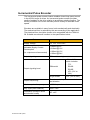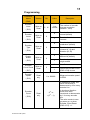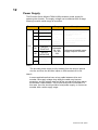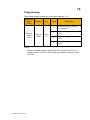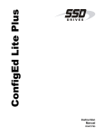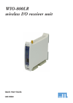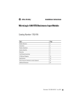
1
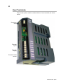
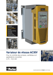
Option Modules
Encoder Option
HA502217U001 Issue 2
Technical Manual
aerospace
climate control
electromechanical
filtration
fluid & gas handling
hydraulics
pneumatics
process control
sealing & shielding
ENGINEERING YOUR SUCCESS
AC30V Encoder Option
Technical Manual
HA502217U001 Issue 2
Compatible with Firmware version 1.5 or later
Copyright 2014 Parker Hannifin Manufacturing Limited
All rights strictly reserved. No part of this document may be stored in a retrieval system, or transmitted in
any form or by any means to persons not employed by a Parker company without written permission from
Parker Hannifin Ltd. Although every effort has been taken to ensure the accuracy of this document it may
be necessary, without notice, to make amendments or correct omissions. Parker cannot accept
responsibility for damage, injury, or expenses resulting therefrom.
Parker Hannifin Manufacturing Limited is referred to throughout this document as Parker.
WARRANTY
The general terms and conditions of sale of goods and/or services of Parker Hannifin Europe
Sarl’s, Luxembourg, Switzerland Branch, Etoy, apply to this product unless otherwise agreed.
The terms and conditions are available on our website
www.parker.com/termsandconditions/switzerland.
FAILURE OR IMPROPER SELECTION OR IMPROPER USE OF THE PRODUCTS
DESCRIBED HEREIN OR RELATED ITEMS CAN CAUSE DEATH, PERSONAL INJURY
AND PROPERTY DAMAGE.
This document and other information from Parker-Hannifin
Corporation, its subsidiaries and authorized distributors
provide product or system options for further investigation by
users having technical expertise.
The user, through its own analysis and testing, is solely
responsible for making the final selection of the system and
components and assuring that all performance, endurance,
maintenance, safety and warning requirements of the
application are met. The user must analyze all aspects of the
application, follow applicable industry standards, and follow
the information concerning the product in the current product
catalog and in any other materials provided from Parker or its
subsidiaries or authorized distributors.
To the extent that Parker or its subsidiaries or authorized
distributors provide component or system options based upon
data or specifications provided by the user, the user is
responsible for determining that such data and specifications
are suitable and sufficient for all applications and reasonably
foreseeable uses of the components or systems.
Safety Information
Requirements
IMPORTANT: Please read this information BEFORE installing the equipment.
Intended Users
This manual is to be made available to all persons who are required to install, configure or
service equipment described herein, or any other associated operation.
The information given is intended to highlight safety issues, EMC considerations, and to
enable the user to obtain maximum benefit from the equipment.
Complete the following table for future reference detailing how the unit is to be installed
and used.
Model Number
(see product label)
Where installed
(for your own information)
INSTALLATION DETAILS
Application Area
The equipment described is intended for industrial motor speed control
utilising AC induction or AC synchronous machines
Personnel
Installation, operation and maintenance of the equipment should be carried
out by competent personnel. A competent person is someone who is
technically qualified and familiar with all safety information and established
safety practices; with the installation process, operation and maintenance of
this equipment; and with all the hazards involved.
Product Warnings
DANGER
Risk of electric
shock
WARNING
Hot
surfaces
Caution
Refer to
documentation
Earth/Ground
Protective
Conductor
Terminal
CAUTION!
APPLICATION RISK
The specifications, processes and circuitry described herein are for guidance only and
may need to be adapted to the user’s specific application. We cannot guarantee the
suitability of the equipment described in this Manual for individual applications.
RISK ASSESSMENT
Under fault conditions, power loss or unintended operating conditions, the drive may not
operate as intended. In particular:
• Stored energy might not discharge to
• The motor's direction of rotation might not
safe levels as quickly as suggested,
be controlled
and can still be present even though
• The motor speed might not be controlled
the drive appears to be switched off
• The motor might be energised
A drive is a component within a drive system that may influence its operation or effects
under a fault condition. Consideration must be given to:
• Stored energy • Supply
• Sequencing
• Unintended operation
disconnects
logic
•
Safety Information
DANGER! - Ignoring the following may result in injury
1. This equipment can endanger life by
exposure to rotating machinery and high
voltages.
5. For measurements use only a meter to IEC
61010 (CAT III or higher). Always begin using
the highest range.
CAT I and CAT II meters must not be used on
this product.
2. The equipment must be permanently
earthed due to the high earth leakage
current, and the drive motor must be
connected to an appropriate safety earth.
6. Allow at least 5 minutes for the drive's
capacitors to discharge to safe voltage levels
(<50V). Use the specified meter capable of
measuring up to 1000V dc & ac rms to confirm
that less than 50V is present between all
power terminals and between power terminals
and earth.
3. Ensure all incoming supplies are isolated
before working on the equipment. Be
aware that there may be more than one
supply connection to the drive.
4. There may still be dangerous voltages
present at power terminals (motor output,
supply input phases, DC bus and the
brake, where fitted) when the motor is at
standstill or is stopped.
7. Unless otherwise stated, this product must
NOT be dismantled. In the event of a fault the
drive must be returned. Refer to "Routine
Maintenance and Repair".
WARNING! - Ignoring the following may result in injury or damage to equipment
SAFETY
Where there is conflict between EMC and Safety requirements, personnel safety shall
always take precedence.
•
Never perform high voltage resistance
checks on the wiring without first
disconnecting the drive from the circuit
being tested.
• All control and signal terminals are SELV,
i.e. protected by double insulation. Ensure
all external wiring is rated for the highest
system voltage.
•
Whilst ensuring ventilation is sufficient,
provide guarding and /or additional safety
systems to prevent injury or damage to
equipment.
• Thermal sensors contained within the motor
must have at least basic insulation.
•
When replacing a drive in an application
and before returning to use, it is essential
that all user defined parameters for the
product’s operation are correctly installed.
• All exposed metalwork in the Inverter is
protected by basic insulation and bonded to
a safety earth.
• RCDs are not recommended for use with
this product but, where their use is
mandatory, only Type B RCDs should be
used.
EMC
•
In a domestic environment this product
may cause radio interference in which
case supplementary mitigation measures
may be required.
•
This equipment contains electrostatic
discharge (ESD) sensitive parts. Observe
static control precautions when handling,
installing and servicing this product.
• This is a product of the restricted sales
distribution class according to IEC 61800-3.
It is designated as “professional equipment”
as defined in EN61000-3-2. Permission of
the supply authority shall be obtained before
connection to the low voltage supply.
Contents.......................................................................................................... Page No.
AC30V Encoder Option ............................................................................................... 1
Introduction ....................................................................................................... 1
Understanding the Product Code ...................................................................... 1
Installation......................................................................................................... 2
User Terminals.................................................................................................. 4
User Wiring ....................................................................................................... 5
Terminal Cable Specification ....................................................... 5
Motor Thermistor ............................................................................................... 6
Programming ........................................................................................ 7
Specification ......................................................................................... 8
Example Application ............................................................................. 8
Incremental Pulse Encoder ............................................................................... 9
Encoder Inputs ................................................................................... 10
Programming............................................................................. 11
Power Supply ..................................................................................... 12
Programming............................................................................. 13
Specification .............................................................................. 14
Differential or Single-Ended Signalling....................................... 16
Example Applications ................................................................ 17
Specification .............................................................................. 21
Encoder Cable .................................................................................... 22
Recommended Encoders ................................................................................ 23
Setting up Closed Loop Operation................................................................... 24
Environmental ................................................................................................. 25
Registration, Evaluation, Authorisation and Restriction of Chemicals (REACH)
........................................................................................................... 25
Restriction of Hazardous Substances (RoHS)..................................... 25
Waste Electrical and Electronic Equipment (WEEE) ........................... 26
AC30V ENCODER OPTION
1
Introduction
The Encoder Option Module is compatible with the AC30V range of
drives, with firmware version 1.5 or later. It offers compatibility with a wide
range of encoders from many manufacturers.
Using this module enables the AC30V to operate in closed-loop speed
control. Alternatively the encoder input may be used as a speed setpoint,
with the drive operating in open-loop (volts / Hz) mode.
Understanding the Product Code
The Encoder Option Module product code is 7004-XX-YY.
Product Code
7004-04-00
7004-04-00
AC30V Encoder Option
Features available
1 x Incremental Pulse Encoder
1 x Motor Thermistor Input
Standard optimized minimal conformal coating
2
Installation
1.
This equipment contains electrostatic discharged (ESD) sensitive parts.
Observe static control precautions when handling, installing and servicing
this product.
2.
Refer to the AC30V product manual Chapter 1: Safety before installing or
removing an encoder option.
3.
4.
Ensure all power is removed from the drive.
5.
Remove the GKP by pulling from the top down, and remove.
After removing the screw, slide the VCM lower cover down slightly and then
remove.
AC30V Encoder Option
3
6.
Click the Option into place and tighten the retaining screw, as shown.
7.
Slide and click back the VCM lower cover, tighten the retaining screw and
slot back the GKP.
AC30V Encoder Option
4
User Terminals
The encoder option module contains blocks of user terminals, as shown
below.
Thermistor
Input
Encoder
Inputs
Encoder
Supply
Encoder Cable
screen
AC30V Encoder Option
5
User Wiring
Terminal Cable Specification
Solid minimum H05(07)V-U 0.2sqmm.
Solid maximum H05(07)V-U 1.5 sqmm.
Flexible minimum H05(07)V-K 0.2 sqmm.
Flexible maximum H05(07)V-K 1.5 sqmm.
W.wire end Ferrule DIN462228 Pt 1 minimum 0.25 sqmm.
W.wire end Ferrule DIN462228 Pt 1 maximum 1.5 sqmm.
W.plastic collar Ferrule DIN462228 Pt4 minimum 0. 25 sqmm (see note 1)
W.plastic collar Ferrule DIN462228 Pt4 maximum 0.75 sqmm (see note 2).
Note 1: Parker SSD part number CI053612U001 (Davico part No.
PET0505)
Note 2: Parker SSD part number CI053612U002 (Davico part No.
PET7575).
AC30V Encoder Option
6
Motor Thermistor
The motor thermistor input provides a means of monitoring motor
temperature in order to protect the motor from a potentially damaging high
temperature.
By default the drive will trip if the motor exceeds a user-defined
temperature threshold thereby preventing the motor temperature from
rising further.
Once tripped, the user can attempt to reset the trip at any time. However
if the motor temperature is still above the trip threshold, the trip cannot be
reset.
Refer to the Chapter 10 in the AC30V product manual (HA501718U002)
for information on trips, possible causes, and how to reset them. A motor
thermistor fault is identified in that manual as ID13 (Motor Overtemp).
Terminal
01
Name
Range
Connect motor thermistor between
these two terminals.
TH1
0Ω to
4500Ω
X22
02
TH2
Description
If a thermistor is not required,
connect these two terminals
together, and ensure PTC
thermistor is selected in parameter
1184.
AC30V Encoder Option
7
Programming
Parameter
Name
Access
Value
Write
or
Read
NTC
Description
(PNO)
Thermistor
Type
(1184)
PTC
KTY
Thermistor type.
Default = PTC
Measured thermistor resistance.
0Ω
Thermistor
Resistance
Read
only
0 to
5000Ω
(1185)
1Ω to
4500Ω
5000Ω
The thermistor
measurement is invalid.
Probably caused by a
faulty encoder board.
The thermistor
measurement is valid.
Note - A short circuit
thermistor reports a small
non-zero value.
The thermistor is opencircuit or the measurement
is invalid.
Thermistor trip level.
Default = 1000Ω
Thermistor
Trip Level
(1004)
AC30V Encoder Option
Write
or
Read
0 to
4500Ω
NTC
The drive trips if the
thermistor resistance is less
than this trip level.
PTC
or
KTY
The drive trips if the
thermistor resistance
exceeds this trip level.
8
Specification
Thermistor resistance
measurement range
0 to 4500Ω
Resistance measurement
accuracy
±5%
Thermistor compatibility
NTC, PTC, KTY
Default = PTC
Measurement supply voltage
1.3V @ 1kΩ
Motor temperature trip
threshold
Resistance threshold set by user.
Default = 1000Ω.
Update rate
1 second
Insulation
Reinforced insulation between
thermistor terminals and drive
electronics.
Important safety information:
Insulation and routing of wiring to the thermistor terminals must be
appropriately rated to ensure the correct degree of insulation to other user
wiring.
Example Application
X22/01
Motor
Thermistor
X22/02
AC30V Encoder Option
9
Incremental Pulse Encoder
The incremental pulse encoder feature enables closed-loop speed control
in the AC30V range of drives. An incremental pulse encoder provides
position feedback to the drive relative to an arbitrary starting position. The
drive’s processor can use the encoder position history to calculate motor
speed.
Encoders are available in many forms, both mechanically and electrically.
The mechanical form is selected by the user according to the application.
The electrical form should be chosen to be compatible with the 7004-0400. Suitable encoders will conform to the specification below:
Feature
Supply Voltage
Value
5V, 12V, 15V or 24V
< 300mA @ 5V
Unloaded Supply Current
Consumption
(i.e. outputs are disconnected)
< 210mA @ 12V
< 160mA @ 15V
< 100mA @ 24V
Output signaling
Differential or single-ended
±3V to ±24V,
which includes:
TTL
RS422
Differential
Output signaling level
RS485
HTL (10V to
30V)
Single-ended
HTL (10V to 24V)
Output sequencing
Two channels, in quadrature or clock
and direction
Maximum pulse frequency
≤ 250kHz per channel
Duty cycle (each channel)
50% ± 10%
Quadrature (except in clock
and direction mode)
90° ± 45°
AC30V Encoder Option
10
Encoder Inputs
The Encoder Option Module 7004-04-00 provides user terminals for
connecting to encoder outputs. A wide specification allows it to be used with a
wide variety of encoders from different manufacturers.
Terminal
01
Name
Range
Channel A
02
Channel /A
03
Channel B
04
Channel /B
05
SUPPLY
POSITIVE
06
SUPPLY
NEGATIVE
±3V to
±24V
(differential)
Or
0V to 24V
(singleended)
X24
07
08
Selectable
5V, 12V,
15V and
24V
Description
Encoder inputs, compatible
with a wide range of
encoders.
The user can program the
inputs to be differential or
single-ended, and
quadrature or clock
(channel A) and direction
(channel B).
Software-selectable power
supply output to encoder.
CABLE
SCREEN
AC30V Encoder Option
11
Programming
Parameter
Name
Access
Bit
Value
Write or
Read
0.. 16
1 to
100000
Description
(PNO)
Encoder
Lines
(1512)
Encoder
Invert
Write or
Read
0
Encoder direction is
normal (default)
1
Encoder direction is
inverted.
0
Encoder inputs are
quadrature (default)
1
Encoder inputs are clock
(channel A, /A) and
direction (B, /B)
0
Encoder inputs are
differential (default)
1
Encoder inputs are
single-ended
0
No effect
1
Forces the encoder count
(PNO 1518) to zero
0 ± 100000
Measured encoder speed
in RPM
0
(1513)
Encoder
Type
Write or
Read
0
(1514)
Singleended
Write or
Read
0
(1515)
Encoder
Count Reset
Write or
Read
0
(1517)
Encoder
Speed
Read
only
The number of encoder
lines per revolution
(default = 1024)
(1516)
In quadrature mode, this
value increments or
decrements by 4 for every
encoder line.
Encoder
Count
(1518)
31
Read
only
-2 to
+(231 – 1)
In clock and direction
mode, this value
increments or decrements
by 1 for every encoder
line.
The value resets to zero
on power-up, or when
Encoder Count Reset
(PNO 1517) = 1.
AC30V Encoder Option
12
Power Supply
The Encoder Option Module 7004-04-00 provides a power supply for
powering the encoder. The supply voltage can be selected from a range
allowing use with a wide range of encoders.
Terminal
Name
Range
01
Channel A
02
Channel /A
±3V to
±24V
(differential)
03
Channel B
Or
04
Channel /B
0V to 24V
(singleended)
05
SUPPLY
POSITIVE
06
SUPPLY
NEGATIVE
X24
07
08
Selectable
5V, 12V,
15V and
24V
Description
Encoder inputs, compatible
with a wide range of
encoders.
The user can program the
inputs to be differential or
single-ended.
Software-selectable power
supply output to encoder.
CABLE
SCREEN
Note 1:
The encoder power supply is fully isolated, from the drive’s internal
circuits, and from the encoder inputs on X24 terminals 01 to 04.
Note 2:
In some applications that have a long cable between drive and
encoder, the supply voltage drop along the cable may become
excessive, and the voltage received at the encoder might drop below
the encoder’s specification. This is most likely with 5V encoders. In
this case, the user should provide a local power supply, or choose an
encoder with a wider supply range.
AC30V Encoder Option
13
Programming
The encoder supply voltage can be set by parameter 1511,
Parameter
Name
(PNO)
Encoder
Supply
(1511)
Access
Write or
Read
Bit
00 to
01
Value
Description
0
Encoder supply voltage =
5V (default)
1
Encoder supply voltage =
12V
2
Encoder supply voltage =
15V
3
Encoder supply voltage =
24V
Note 3:
Where encoders support supplies within the range 8V to 30V, the
voltage should normally be set as high as possible to improve noise
immunity.
AC30V Encoder Option
14
Specification
Feature
Supply output voltage
Output voltage accuracy
Typical current capacity
Value
User selectable 5V, 12V, 15V, 24V
5V
Minimum = 5.02V
Typical = 5.15V
Maximum = 5.27V
12V, 15V, 24V
±7%
5V
Typical 450mA. Guaranteed 300mA
12V
Typical 350mA. Guaranteed 210mA
15V
Typical 280mA. Guaranteed 160mA
24V
Typical 175mA. Guaranteed 100mA
Fault protection
No damage will be caused by overload or
short circuit. It may be necessary to cycle
power to the drive or temporarily disconnect
the encoder to recover from a fault.
Isolation
The encoder supply is galvanically isolated
from the drive and from the encoder input
terminals. Isolation is functional only,
intended to eliminate ground loops. It is not
a safety isolation barrier.
AC30V Encoder Option
15
Cable Screen Connection
Terminals X24/07 and X24/08 are for connection to the encoder cable
screen. Either one or both terminals can be used; they are connected
together internally.
Terminal
Name
Range
01
Channel A
02
Channel /A
±3V to
±24V
(differential)
03
Channel B
Or
04
Channel /B
0V to 24V
(singleended)
05
SUPPLY
POSITIVE
06
SUPPLY
NEGATIVE
X24
07
08
Selectable
5V, 12V,
15V and
24V
Description
Encoder inputs, compatible
with a wide range of
encoders.
The user can program the
inputs to be differential or
single-ended.
Software-selectable power
supply output to encoder.
CABLE
SCREEN
Important notes:
In order to meet the Electro-Magnetic Compatibility (EMC) specification,
both the motor screen and encoder screen should both be connected
directly at the motor and drive, and not interrupted.
If the motor cable screen is not continuous or not connected directly at the
motor and drive, earth currents that should return to the drive through the
motor cable screen may instead return via the encoder cable screen, and
unreliable encoder operation may result.
If it is not possible for the motor cable screen to be continuous or not
connected directly at the motor or drive, encoder reliability may be
improved by disconnecting the encoder cable screen, preferably at the
encoder. In this case, it is the user’s responsibility to ensure the system
works reliably.
AC30V Encoder Option
16
Differential or Single-Ended Signalling
Differential signalling is the preferred connection method, especially in
noisy environments or where the transmission distance is long.
Differential Signaling Connections (PNO 1515 = 0)
Encoder
7004-04-00
X24/01
Channel A
X24/02
Isolation
X24/03
Channel B
X24/04
Single-Ended Signaling Connections (PNO 1515 = 1)
Encoder
Channel A
7004-04-00
X24/01
X24/02
Isolation
Channel B
X24/03
X24/04
AC30V Encoder Option
17
Example Applications
The following pages show the relationship between signal inputs of
different types, the Encoder Type and Encoder Invert.
Encoder Type = Quadrature (PNO 1514 = 0)
Encoder Invert = False (PNO 1513 = 0)
If Channel A leads Channel B, the encoder is considered to be rotating
clockwise. If Channel B leads Channel A, the encoder is considered to be
rotating anti-clockwise.
Clockwise
Anti-Clockwise
PNO 1518 increments on
every edge
PNO 1518 decrements on
every edge
A
B
(See Note)
Note:
A = Channel A relative to Channel /A
B = Channel B relative to Channel /B
AC30V Encoder Option
18
Encoder Type = Clock / Direction (PNO 1514 = 1)
Encoder Invert = False (PNO 1513 = 0)
If Channel B is low, the encoder is considered to be rotating clockwise. If
Channel B is high, the encoder is considered to be rotating anti-clockwise.
Clockwise
Anti-Clockwise
A
B
(See Note)
PNO 1518 increments
on every rising edge
PNO 1518 decrements
on every rising edge
Note:
A = Channel A relative to Channel /A
B = Channel B relative to Channel /B
AC30V Encoder Option
19
Encoder Type = Quadrature (PNO 1514 = 0)
Encoder Invert = True (PNO 1513 = 1)
If Channel A leads Channel B, the encoder is considered to be rotating
anti-clockwise. If Channel B leads Channel A, the encoder is considered
to be rotating clockwise.
Clockwise
Anti-Clockwise
PNO 1518 increments on
every edge
PNO 1518 decrements
on every edge
A
B
(See Note)
Note:
A = Channel A relative to Channel /A
B = Channel B relative to Channel /B
AC30V Encoder Option
20
Encoder Type = Clock and Direction (P 1514 = 1)
Encoder Invert = True (PNO 1513 = 1)
If Channel B is high, the encoder is considered to be rotating clockwise. If
Channel B is low, the encoder is considered to be rotating anti-clockwise.
Clockwise
Anti-Clockwise
A
B
(See Note)
PNO 1518 increments on
every rising edge
PNO 1518 decrements
on every rising edge
Note:
A = Channel A relative to Channel /A
B = Channel B relative to Channel /B
AC30V Encoder Option
21
Specification
Feature
Value
Absolute maximum input voltage
(A relative to /A and B relative to
/B)
Recommended input voltage
range (A relative to /A and B
relative to /B)
Input current
Input threshold voltage (typical)
Input Hysteresis (typical)
±30V
Differential
±3V to ± 24V
Single-ended
0 to +24V
≤10mA per channel
Differential
+2V and -2V
Single-ended
Differential
+7V
4V centred at
0V
Single-ended
Maximum pulse rate per channel
Isolation
AC30V Encoder Option
None
250kHz
The encoder inputs are
galvanically isolated from the
drive, from each other and from
the encoder supply. Isolation is
functional only, intended to
eliminate ground loops. It is not a
safety isolation barrier.
22
Encoder Cable
The ideal cable should have:
•
Three twisted pairs (one pair each for power supply, Channel A
and Channel B)
•
Each pair individually screened
•
Overall shield
•
Characteristic impedance 100Ω to 130Ω
•
Maximum cable length of 50m
e.g. Belden 8163
With 5V encoders in particular, voltage drop on the supply should be
considered, and the wire gauge and cable length chosen appropriately. If
necessary, a local power supply should be provided.
Wire gauge can be estimated from:
Resista nce / metre ≤
Supply Voltage − Encoder Voltage
2 × Cable Length × Current
Where:
Resistance / metre = individual conductor resistance per metre
Supply Voltage = 5.02V 1
Encoder Voltage = minimum supply voltage required by the 5V
encoder
Cable length from encoder to 7004-04-00, measured in metres
Current = Current drawn by the encoder in amps
= Unloaded current from encoder specification + 20mA
Example:
Encoder voltage = 5.00V ± 5% = 4.75V minimum
Cable length = 10 metres
Unloaded current = 150mA
5.02 − 4.75
2 × 10 × 0.17
= 0.079Ω / metre
Conductor Resista nce ≤
1
Assuming 5V supply is selected, the minimum output = 5.02V.
AC30V Encoder Option
23
Recommended Encoders
The following encoders have been tested and approved for use with the
7004-04-00:
AC30V Encoder Option
24
Setting up Closed Loop Operation
Please refer to the AC30V user manual HA501718U001 for information
on setting up and running the drive in closed loop operation using
encoder feedback.
AC30V Encoder Option
25
Environmental
Registration, Evaluation, Authorisation and
Restriction of Chemicals (REACH)
The Regulation (EC) No 1907/2006 of the European Parliament and of
the Council of 18 December 2006 concerning the Registration,
Evaluation, Authorization, and Restriction of Chemicals (REACH) entered
into force on June 1, 2007. Parker agrees with the purpose of REACH
which is to ensure a high level of protection of human health and the
environment. Parker is compliant with all applicable requirements of
REACH.
The registration requirements do not apply to Parker since it is neither a
manufacturer nor an importer of preparations into Europe.
However, product (article) manufacturers or importers into Europe are
obligated under Article 33 of REACH to inform recipients of any articles
that contain chemicals on the Substances of Very High Concern (SVHC)
candidate list above a 0.1% concentration (by weight per article). As of
19th December 2011 VSD products manufactured and marketed by
Parker do not contain substances on the REACH SVHC candidate list in
concentrations greater than 0.1% by weight per article. Parker will
continue to monitor the developments of the REACH legislation and will
communicate with our customers according to the requirement above.
WARNING
Restriction of Hazardous Substances (RoHS)
This product is in full compliance with RoHS Directive 2011/65/EU, with
respect to the following substances:
1) Lead (Pb),
2) Mercury (Hg),
3) Cadmium (Cd),
4) Hexavalent chromium (Cr (VI)),
5) Polybrominated biphenyls (PBB),
6) Polybrominated diphenyl ethers (PBDE).
AC30V Encoder Option
26
Waste Electrical and Electronic Equipment (WEEE)
WARNING
Waste Electrical and Electronic Equipment must not be disposed of with domestic waste.
It must be separately collected according to
local legislation and applicable laws.
WARNING
Parker Hannifin Company, together with local distributors and in
accordance with EU directive 2002/96/EC, undertakes to withdraw and
dispose of its products, fully respecting environmental considerations.
For more information about how to recycle your Parker supplied waste
equipment, please contact your local Parker Service Centre.
Packaging
During transport our products are protected by suitable packaging. This is
entirely environmentally compatible and should be taken for central
disposal as secondary raw material.
AC30V Encoder Option
Parker Worldwide
AE – UAE, Dubai
Tel: +971 4 8127100
[email protected]
FI – Finland, Vantaa
Tel: +358 (0)20 753 2500
[email protected]
PT – Portugal, Leca da Palmeira
Tel: +351 22 999 7360
[email protected]
AR – Argentina, Buenos Aires
Tel: +54 3327 44 4129
FR – France, Contamine s/Arve
Tel: +33 (0)4 50 25 80 25
[email protected]
RO – Romania, Bucharest
Tel: +40 21 252 1382
[email protected]
GR – Greece, Athens
Tel: +30 210 933 6450
[email protected]
RU – Russia, Moscow
Tel: +7 495 645-2156
[email protected]
HK – Hong Kong
Tel: +852 2428 8008
SE – Sweden, Spånga
Tel: +46 (0)8 59 79 50 00
[email protected]
AT – Austria, Wiener Neustadt
Tel: +43 (0)2622 23501-0
[email protected]
AT – Eastern Europe,
Wiener Neustadt
Tel: +43 (0)2622 23501 900
[email protected]
AU – Australia, Castle Hill
Tel: +61 (0)2-9634 7777
HU – Hungary, Budapest
Tel: +36 1 220 4155
[email protected]
AZ – Azerbaijan, Baku
Tel: +994 50 2233 458
[email protected]
IE – Ireland, Dublin
Tel: +353 (0)1 466 6370
[email protected]
SK – Slovakia, Banská Bystrica
Tel: +421 484 162 252
[email protected]
BE/LU – Belgium, Nivelles
Tel: +32 (0)67 280 900
[email protected]
IN – India, Mumbai
Tel: +91 22 6513 7081-85
SL – Slovenia, Novo Mesto
Tel: +386 7 337 6650
[email protected]
BR – Brazil, Cachoeirinha RS
Tel: +55 51 3470 9144
IT – Italy, Corsico (MI)
Tel: +39 02 45 19 21
[email protected]
BY – Belarus, Minsk
Tel: +375 17 209 9399
[email protected]
JP – Japan, Tokyo
Tel: +81 (0)3 6408 3901
SG – Singapore
Tel: +65 6887 6300
TH – Thailand, Bangkok
Tel: +662 717 8140
TR – Turkey, Istanbul
Tel: +90 216 4997081
[email protected]
KR – South Korea, Seoul
Tel: +82 2 559 0400
CA – Canada, Milton, Ontario
Tel: +1 905 693 3000
TW – Taiwan, Taipei
Tel: +886 2 2298 8987
KZ – Kazakhstan, Almaty
Tel: +7 7272 505 800
[email protected]
CH – Switzerland, Etoy
Tel: +41 (0)21 821 87 00
[email protected]
UA – Ukraine, Kiev
Tel +380 44 494 2731
[email protected]
MX – Mexico, Apodaca
Tel: +52 81 8156 6000
CL – Chile, Santiago
Tel: +56 2 623 1216
UK – United Kingdom,
Warwick
Tel: +44 (0)1926 317 878
[email protected]
MY – Malaysia, Shah Alam
Tel: +60 3 7849 0800
CN – China, Shanghai
Tel: +86 21 2899 5000
CZ – Czech Republic, Klecany
Tel: +420 284 083 111
[email protected]
NL – The Netherlands,
Oldenzaal
Tel: +31 (0)541 585 000
[email protected]
DE – Germany, Kaarst
Tel: +49 (0)2131 4016 0
[email protected]
NO – Norway, Asker
Tel: +47 66 75 34 00
[email protected]
DK – Denmark, Ballerup
Tel: +45 43 56 04 00
[email protected]
NZ – New Zealand, Mt Wellington
Tel: +64 9 574 1744
US – USA, Cleveland
Tel: +1 216 896 3000
VE – Venezuela, Caracas
Tel: +58 212 238 5422
ZA – South Africa,
Kempton Park
Tel: +27 (0)11 961 0700
[email protected]
PL – Poland, Warsaw
Tel: +48 (0)22 573 24 00
[email protected]
ES – Spain, Madrid
Tel: +34 902 330 001
[email protected]
European Product Information Centre
Free phone: 00 800 27 27 5374
(from AT, BE, CH, CZ, DE, EE, ES, FI, FR, IE,
IL, IS, IT, LU, MT, NL, NO, PT, SE, SK, UK)
© 2012 Parker Hannifin Corporation. All rights reserved.
Parker Hannifin Manufacturing Limited,
Automation Group, SSD Drives Europe,
New Courtwick Lane, Littlehampton,
West Sussex BN17 7RZ
United Kingdom
Tel: +44(0)1903 737000
Fax: +44(0)1903 737100
www.parker.com/ssd
*HA502217U001_02*