1
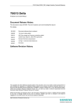
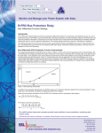
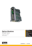
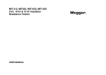
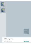
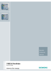
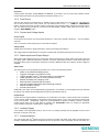
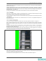
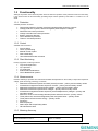
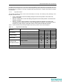
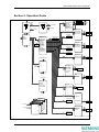
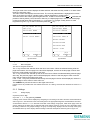
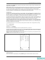
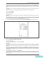
7SG13 Delta P20015 FM1 User Manual 7SG13 Delta Protection and Control Relays Document Release History This document is issue 2010/02 The list of revisions up to and including this issue is: Pre release 2010/02 Document reformat due to rebrand 2004/07 Second Issue – General update 2003/02 v2 Page 1: removed invalid references 2003/01 First issue Software Revision History The copyright and other intellectual property rights in this document, and in any model or article produced from it (and including any registered or unregistered design rights) are the property of Siemens Protection Devices Ltd. No part of this document shall be reproduced or modified or stored in another form, in any data retrieval system, without the permission of Siemens Protection Devices Ltd., nor shall any model or article be reproduced from this document unless Siemens Protection Devices Ltd. consent. While the information and guidance given in this document is believed to be correct, no liability shall be accepted for any loss or damage caused by any error or omission, whether such error or omission is the result of negligence or any other cause. Any and all such liability is disclaimed. ©2010 Siemens Protection Devices Ltd. 7SG13 Delta P20015 FM1 User Manual Contents Contents ..................................................................................................................................................2 List of Figures.........................................................................................................................................3 List of Tables ..........................................................................................................................................3 Section 1: Relay Description.................................................................................................................4 1.1 Overview ...................................................................................................................................4 1.2 Hardware...................................................................................................................................4 1.2.1 Case .............................................................................................................................4 1.2.2 User Interface / Fascia .................................................................................................4 1.2.3 Front Cover ..................................................................................................................6 1.2.4 Current and Voltage Inputs ..........................................................................................6 1.2.5 Status Inputs and Output Relays .................................................................................6 1.2.6 Auxiliary Supply............................................................................................................6 1.2.7 Communications ..........................................................................................................6 1.2.8 Terminals......................................................................................................................7 1.2.9 Internal Construction ....................................................................................................7 1.3 Functionality ..............................................................................................................................8 1.3.1 Protection .....................................................................................................................8 1.3.2 Control..........................................................................................................................8 1.3.3 Plant Monitoring ...........................................................................................................8 1.3.4 Measurements .............................................................................................................8 1.3.5 Metering Accuracy .......................................................................................................8 1.3.6 System Data.................................................................................................................9 1.3.7 General.......................................................................................................................10 Section 2: Operation Guide .................................................................................................................12 2.1 User Interface Operation.........................................................................................................13 2.1.1 Mimic Display and Control of Plant ............................................................................13 2.1.2 Menu System .............................................................................................................13 2.1.3 Settings ......................................................................................................................14 2.1.4 Instruments ................................................................................................................16 2.1.5 Fault Displays.............................................................................................................17 2.1.6 Viewing and Resetting Flag LEDs .............................................................................17 2.1.7 Operation with Front Cover Fitted..............................................................................18 2.1.8 Contrast Adjustment...................................................................................................18 2.2 Operation using ReyDisp Evolution ........................................................................................18 2.2.1 Keyswitch Position .....................................................................................................19 Section 3: Installation ..........................................................................................................................20 3.1 Unpacking, Storage and Handling ..........................................................................................20 3.2 Recommended Mounting Position..........................................................................................20 3.3 Relay Dimensions and Weight................................................................................................20 3.4 Wiring ......................................................................................................................................20 3.4.1 Communications ........................................................................................................20 3.5 Fixings.....................................................................................................................................21 3.5.1 Crimps ........................................................................................................................21 3.5.2 Panel Fixing Screws...................................................................................................21 3.6 Ancillary Equipment ................................................................................................................21 Section 4: Commissioning ..................................................................................................................22 4.1 Before Testing.........................................................................................................................22 4.1.1 Safety .........................................................................................................................22 4.1.2 Sequence of Tests .....................................................................................................22 4.1.3 Test Equipment ..........................................................................................................22 4.1.4 Precautions ................................................................................................................23 ©2010 Siemens Protection Devices Ltd. P20015 Page 2 of 27 7SG13 Delta P20015 FM1 User Manual 4.1.5 Applying Settings .......................................................................................................23 4.2 Tests .......................................................................................................................................23 4.2.1 Inspection ...................................................................................................................23 4.2.2 Insulation Tests ..........................................................................................................23 4.2.3 Secondary Injection Tests..........................................................................................24 4.2.4 Status Inputs ..............................................................................................................24 4.2.5 Output Relays ............................................................................................................24 4.2.6 Primary Injection Tests...............................................................................................24 4.3 Putting into Service .................................................................................................................24 Section 5: Testing and Maintenance ..................................................................................................25 5.1 Periodic Tests .........................................................................................................................25 5.2 Maintenance............................................................................................................................25 5.2.1 Module Handling Precautions ....................................................................................25 5.2.2 Removal of a Module .................................................................................................25 5.2.3 Insertion of a Module..................................................................................................25 5.3 Troubleshooting ......................................................................................................................26 5.4 Defect Report ..........................................................................................................................27 List of Figures Figure 1-1 Figure 1-2 Figure 2-1 Figure 2-2 Figure 2-3 Figure 2-4 Figure 2-5 Figure 2-6 Relay in Vertical Size 12 Case .......................................................................................................... 5 Interior of a Relay .............................................................................................................................. 7 Menu Structure................................................................................................................................ 12 Example Menu Screens .................................................................................................................. 14 Example Setting Displays................................................................................................................ 15 Setting Editing ................................................................................................................................. 15 Instrument Display........................................................................................................................... 16 Fault Data Display ........................................................................................................................... 17 List of Tables Table 1-1 Table 3-1 Table 5-1 Keyswitch Functionality ................................................................................................................... 11 Wire crimp sizes .............................................................................................................................. 21 Troubleshooting Guide .................................................................................................................... 26 ©2010 Siemens Protection Devices Ltd. P20015 Page 3 of 27 7SG13 Delta P20015 FM1 User Manual Section 1: Relay Description 1.1 Overview The Reyrolle modular range of products combines power system protection with the most up to date microprocessor technology to create a highly flexible solution for all transmission and distribution substation secondary applications. Within this range, these Protection and Control relays are specifically designed to integrate the bay level control and protection requirements into a single box, providing an attractive solution for most distribution requirements. Features The following features are available within these Relays: • • • • • • • • • • • • • Delayed (IDMTL) and instantaneous overcurrent protection, for phase currents, earth currents and negative phase sequence current Thermal overload protection Broken conductor detection Voltage protections for phase voltages, neutral voltage and negative phase sequence voltage Auto-reclosing with check synchronising Trip circuit supervision Circuit breaker failure protection CT and VT supervision Mimic display of plant status, with user-friendly local control Comprehensive metering functions User-programmable interlocking schemes Programmable user logic Remote control and monitoring through IEC 60870-5-103 protocol. The Relays benefit from the following features, which are provided on all products in the Modular range: • • • • • • • • • True RMS measurement for instrumentation Status inputs with independent pick-up and drop-off timers and logic inversion Flexible supply voltage ranges Low AC/DC burden Multiple independent settings groups Self, hand and electrical reset contacts Extensive fault, sequence of event and disturbance recorder IEC 60870-5-103 fibre-optic communications Continuous self-supervision of operation and power supply Each of these functions is fully specified in the appropriate Technical Reference documentation. The functions provided in a specific model will be confirmed on order, and will be specified in the Diagrams and Parameters documentation for the appropriate product. 1.2 Hardware 1.2.1 Case The product is housed in a vertical case designed to fit directly into circuit breaker panels. The standard case has a height of 312 mm, a width of 177 mm, and a behind panel depth (with wiring clearance) of 242 mm. An additional 75 mm clearance should be allowed if the fibre optic communications cables are fitted. The hardware is modular and, for maintenance or upgrade purposes, each module can be withdrawn from the front of the case. Shorting contacts ensure that CT circuits and normally closed contacts remain short-circuited. 1.2.2 User Interface / Fascia The user interface is designed to provide an easy and user-friendly method of controlling plant, entering settings and retrieving data from the product. ©2010 Siemens Protection Devices Ltd. P20015 Page 4 of 27 7SG13 Delta P20015 FM1 User Manual Figure 1-1 • Relay in Vertical Size 12 Case The fascia is hinged on the bottom edge and is secured on the upper edge by two screws at the left and right. A plastic handle is provided to open the fascia door. Caution. Care should be taken if the door is unscrewed while the relay is mounted in the panel. Relay Information The Reyrolle logo appears in the top left corner. At the bottom left an information label is provided which contains the model name, article number, configuration identification, serial number and nominal ratings of energising quantities. Liquid Crystal Display A 256 x 128 pixel, graphical, backlit liquid crystal display (LCD) is used to present the bay mimic, plant status, settings, instruments and fault data in a graphical and textual format. The display backlighting is turned off to conserve power if no pushbuttons are pressed for a settable period. ‘Protection Healthy’ LED The green LED indicates that the auxiliary supply has been applied to the relay, and that the relay is operating correctly. If a permanent fault is detected by the internal relay watchdog, then this LED will continuously flash. Indication LEDs Eight red LEDs allow indication of protection function pick-up or operation, or other functions that the user programs. However, these LEDs are used to display four pages of indications, each with on-screen description of 13 characters, allowing up to 32 alarm/trip/status indications to be displayed. Each of these virtual LEDs can be defined as self-reset or hand-reset. Once lit, hand-reset LEDs can be extinguished by pressing the TEST/RESET key, or using IEC 60870-5-103 communications, or by energising a status input that has been programmed to reset latched relays and the trip flag. If the relay powers down the LED indications are retained and when powered up again the LED information is still available. Keypad Nine keys are provided to control the plant and the functions of the relay. In common with other Reyrolle products the following keys are provided: , , ENTER, CANCEL and . In addition, to facilitate the control and monitoring aspects of the Relay, the following keys are provided: VIEW, TEST/RESET, I and 0. ©2010 Siemens Protection Devices Ltd. P20015 Page 5 of 27 7SG13 Delta P20015 FM1 User Manual Keyswitch A three-position keyswitch, Local, Remote and Service, is provided to set the control and protection status. Further detail of the function of the keyswitch is provided in section 1.3.7.4. 1.2.3 Front Cover After the relay has been commissioned it is sealed by fixing a clear plastic cover over the front. This allows the user to see the entire front of the product, but only allows access to the , , VIEW and TEST/RESET buttons, allowing all areas of the menu system to be viewed, but preventing setting changes and control actions. The only ‘action’ that is permitted is to reset the Fault Data display, latched output relays and the trip LED by using the TEST/RESET button. 1.2.4 Current and Voltage Inputs Current Inputs Current inputs are used for the current based protections –overcurrent, thermal overload etc. – and for metering purposes. CTs of 1A and 5A nominal rating may be connected to the inputs. Voltage Inputs Voltage inputs are used for voltage protections, check synchronising and metering. The voltage inputs are appropriate for connection to phase-earth and phase-phase (63.5V and 110V) VTs. 1.2.5 Status Inputs and Output Relays Status inputs allow digital inputs to the product from plant and supervisory controls whilst output relays are used for tripping, plant control and supervisory indication. The basic input/output provision is three status inputs and five output relays (three of which have changeover contacts). Additional inputs and outputs in blocks of eight are available. Status Inputs The status inputs can be programmed to perform one or more of the following functions: • • • • • • • • • Switch to an alternative settings group. Trigger the storage of a waveform record. Trigger operation of the I2 summation and trip count features. Inhibit operation of any one or more protection functions. Monitor the health of the tripping circuit. Electrical reset of latched output contacts. Input into programmable logic and interlocking schemes. Monitor the status of plant. Provide control inputs. Additionally, each input can be independently programmed to be inverted (i.e. de-energising the input activates the signal), and operate with time delayed pick-up and/or time delayed drop-off. Output Relays Outputs are user programmable to operate from any combination of functions. In their normal mode of operation, output contacts remain energised for the duration of their driving signal, or for a user programmed minimum time of up to 60 seconds. Alternatively, outputs can be programmed to operate as latching contacts if required. Latched output relays can be reset either by pressing the TEST/RESET button, by sending an appropriate communications command or electrically via a status input. 1.2.6 Auxiliary Supply A DC voltage of the appropriate level (or 110v ac if an ac auxiliary is fitted) must be supplied onto the correct terminals on the rear of the case. 1.2.7 Communications Two pairs of fibre-optic STTM (BFOC/2.5) bayonet connectors (COM1 and COM2, each made up a transmitter and receiver), optimised for glass-fibre, are fitted to the rear of the case. These are typically used for connection to a ©2010 Siemens Protection Devices Ltd. P20015 Page 6 of 27 7SG13 Delta P20015 FM1 User Manual control system. The two ports are redundant in that if one connection fails, communication will automatically be switched to the other port. A third communications port, with a 25-pin female RS232 connector, is mounted on the fascia. A setting is available to direct the port to either the front, rear, or it can be set to auto detect. When used in this mode the port will automatically switch COM2 from the rear of the case. This port can be used for dialogue communications to ReyDisp Evolution – see section 2.2. In common with all Modular II products, Relay uses IEC 60870-5-103 as its communications standard. 1.2.8 Terminals These are of a modular design, consisting of 28 terminals per block. All inputs and outputs (except for the serial communications interface and IRIG B) are made through these connectors. The rear terminals are designed to take two wires terminated using ring crimps and are secured using M4 screws – see section 3.5. The identification of the connections to the terminal blocks can be found in the appropriate Diagrams and Parameters Document. 1.2.9 Internal Construction The interior of the relay is divided into a number of slots, into which modules are inserted – see Figure 1-2. When a module is inserted into the case, contacts on the rear of the modules mate with contacts on the inside rear of the case. Shorting contacts are provided on CT circuits so CTs remain short circuited when modules are removed. Coding pins ensure that modules are inserted into the correct slot within the case. In addition, to correctly identify the location of each module, the module article number is printed on the module, and a list of all modules is printed on the inside of the fascia door. The ability to remove and insert modules in this manner allows replacement or relay upgrade to occur, without the need to remove wiring from the case with the ensuing recommissioning tests. Figure 1-2 • Interior of a Relay The module in the lowest slot contains the fibre-optic connections at the rear, and has the door hinge mounted on it at the front. Therefore, this module is fixed in place. The modules are connected together with one or more ribbon cables, as illustrated in Figure 1-2. ©2010 Siemens Protection Devices Ltd. P20015 Page 7 of 27 7SG13 Delta P20015 FM1 User Manual 1.3 Functionality Although the position of the fascia keyswitch does not affect the operation of the protection functions in the Relay, it can restrict access to this functionality (including output contact operation). See Table 1-1 in section 1.3.7 for detail. 1.3.1 Protection Available protection functions: • • • • • • • Overcurrent protection of phase, earth and negative phase sequence currents Voltage protection of phase, earth and negative phase sequence voltages Directional overcurrent protection Voltage controlled overcurrent protection Broken conductor detection Circuit breaker fail protection Thermal / overload protection 1.3.2 Control Available control functions: • • • • • Auto-reclosing Check synchronising Manual control of plant Plant interlocking User defined automation schemes 1.3.3 Plant Monitoring Primary equipment monitoring functions: • • • • • Trip circuit supervision CT supervision VT supervision External alarms/indications Circuit Breaker/Plan position 1.3.4 Measurements Indicative metering is provided. The instruments available are dependent on the model (VT inputs are required for voltage, power and energy metering), but include: • • • • • • • • • • • • Measured instantaneous phase and earth (neutral) currents – primary and secondary values Instantaneous negative and zero sequence currents – primary and secondary values Measured instantaneous phase-phase voltages – primary and secondary values Measured instantaneous phase-earth voltages – primary and secondary values Instantaneous negative and zero sequence (neutral displacement) voltages – primary and secondary values Maximum, minimum and average demand phase and earth currents – primary values Three-phase real, reactive and apparent power and power factor – primary values Three-phase real and reactive energy – primary values Frequency Element pickups Status Input and Output Relay status CB maintenance data 1.3.5 Metering Accuracy Currents (IA, IB, IC) Tolerance 1% of actual value or 0.5 % In ©2010 Siemens Protection Devices Ltd. Range 10% In to 200%In P20015 Page 8 of 27 7SG13 Delta P20015 FM1 User Manual Voltage(VAN, VBN, VCN) Tolerance 1% of actual value or 0.5 % In Range 10% In to 120%In Active Power, P (Watts) Tolerance typically < 3% of Actual value Range 20%Nom to 120%Nom for cosv of 0.707 to 1 Reactive Power, Q (Var) Tolerance typically < 3% of Actual value Range 20%Nom to 120%Nom for sinv of 0.707 to 1 Apparent Power, S (VA) Tolerance typically < 3% of Actual value Range 20%Nom to 120%Nom Frequency Tolerance 1% of Actual value Range 10Hz – 100Hz Default instrumentation screens The menu presentation of the various instruments allows the user to view a single screen at a time. However, for in-service use, it may be desirable for a small number of high interest, user-selected screens to be presented automatically without user intervention, e.g. display of the primary load currents, primary voltages, power flow and the trip count. This can be achieved by setting multiple default screens. After a user-defined period without a key press, the product will enter default instrument mode and display each default instrument in turn, including the mimic diagram, for a period of 5 seconds each. If default screens are set, the mimic screen will be redrawn after the default screens have gone through the cycle. It takes a few seconds to redraw the mimic screen. Any key press while displaying default instruments will result in a return to the “Mimic” screen at the top of the menu structure. See section 2.1.4 for operation. 1.3.6 System Data Data records are available in three forms: fault records, waveform records and event records. 1.3.6.1 Time stamping All records are stamped with time and date using the real-time clock. If the product is de-energised then a capacitor provides a back-up supply to the real-time clock for a limited period. Time and date can be set either via the relay fascia using appropriate commands in the System Configuration menu, using the IRIG-B input, or via the communications interface. In the latter case, relays connected in a communications network can be synchronised by a global command. Alternatively, synchronising pulses can be received via a status input. Energisation of the appropriate input will result in the clock being synchronised to the nearest second or minute, as appropriate to the controlling device. 1.3.6.2 Fault records When any protection element operates a fault record is stored and displayed on the Fault Data display, giving the date and time of fault. The fascia LEDs will give indication of the status of all elements at the time of trip. (The first eight indications will be displayed on the LEDs – the VIEW key is pressed to view further pages of indications.) Ten fault records are available, giving time and date of trip, measured quantities and type of fault. This display is held until the Test/Reset button is pressed, upon which latched LEDs turn off and any latched output relays are reset. 1.3.6.3 Waveform records Disturbance recorder The waveform record feature stores analogue and digital information for all current and voltage inputs, status inputs and output relays. Waveform storage is triggered by operation of any protection element. In addition, a record can be triggered remotely via a status input or via the serial communications interface. ©2010 Siemens Protection Devices Ltd. P20015 Page 9 of 27 7SG13 Delta P20015 FM1 User Manual The storage capacity can be distributed between number of records and record length as follows: one 5-second record, two 2-second records, or five 1-second records. The pre-trigger percentage of each record can be defined. When all records are full, any new record will overwrite the oldest. All records are time and date stamped. Waveform records are stored in RAM with a capacitor providing back-up during breaks in auxiliary supply. Twenty-four hour storage A rolling buffer of storage is used to make two records available, each showing twenty-four hours of data. The first gives the record for the previous calendar day, while the second provides the latest twenty-four hours prior to the time of viewing. Each of these records gives the following values stored at 1 minute intervals: RMS phase currents, RMS phaseearth voltages, RMS phase-phase voltages and frequency. 1.3.6.4 Sequence of event records The event recorder allows the time tagging of any change of state. Each event is logged with the full date and time and actual event condition. The following events can be logged: • • • • • • • • Change of setting (though not the detail of the setting change). In addition, indication of which group of settings is active. Change of state of output relays Change of state of status inputs Change of state of any function Trip indication reset Power on / reset Keyswitch position Front port accessed The event storage buffer holds 500 records. When the event buffer is full, then any new record over writes the oldest. Event records are stored in RAM with a capacitor providing back-up during breaks in auxiliary supply. The event record store can be erased when viewing the “events stored” instrument screen and pressing the TEST/RESET button. 1.3.7 General 1.3.7.1 Multiple Settings Groups Eight settings groups are provided, making it possible to edit one group while the product functions operate using another ‘active’ group. The relay can then be switched from one group of settings to another to suit alterations in the power system configuration. A change of group can be achieved either locally at the relay fascia, remotely via a communications interface command or automatically by energisation of a status input. In the case of the latter method, the ‘Settings Group Select’ setting is used to configure any one of the status inputs to select a settings group. The selected group is then made active if the status input is energised and remains active for as long as the input remains energised. 1.3.7.2 Self Monitoring In common with all Modular products, the Relay incorporates a number of self-monitoring features listed below, each of which initiates a reset sequence that can be used to generate an alarm output. In addition, the Protection Healthy LED gives visual indication. • • • • • Power supply watchdog Microprocessor watchdog Program and data memory test using CRC ADC self-checking Change to expected hardware • Any failure is detected with sufficient time warning so that the microprocessor can be shut down in a safe and controlled manner. 1.3.7.3 Password Feature The programmable password feature enables the user to enter a four character alphanumeric code. If the user attempts to change a setting, the password is requested before any setting alterations are allowed. Once the password has been validated, the user is said to be “logged on” and any further changes can be made without reentering the password. If no more changes are made within I hour then the user will automatically be “logged out”, ©2010 Siemens Protection Devices Ltd. P20015 Page 10 of 27 7SG13 Delta P20015 FM1 User Manual re-enabling the password feature. Note that the password validation screen also displays a numerical code. If the password is lost or forgotten, this code can be communicated to Reyrolle Protection by authorised personnel, and the password can be retrieved. The relay is supplied with the password set to “NONE” which means the feature is de-activated. 1.3.7.4 Keyswitch Position The keyswitch provides security for the control functionality of the relay. The following is the philosophy of the keyswitch positions in brief: • • • Local – allows plant control and setting changes from the local position. All functions are operating normally. Remote – allows plant control and setting changes from the remote position. All functions are operating normally. Service – no plant control is allowed. Local setting changes are allowed. Changes to the configuration (e.g. loading new mimic and logic diagrams) are allowed. The protection will not energise any output relays or generate events, but will generate LED flag indication. Table 1-1 shows the different functionality available when the key switch is in the various positions. Table 1-1 Keyswitch Functionality Key Position Function View settings Change settings Control plant Protection and automation functions Remote Local Service Local – fascia keypad or RS232 port 9 9 9 Remote – rear fibre ports 9 9 9 9 9 Local – fascia keypad or RS232 port Remote – rear fibre ports 9 Local – fascia keypad or RS232 port 9 Remote – rear fibre ports 9 Output contacts 9 9 Event generation 9 9 LEDs 9 9 Extract data records – waveforms, stored events, instruments ©2010 Siemens Protection Devices Ltd. 9 9 Configuration changes 9 9 9 P20015 Page 11 of 27 7SG13 Delta P20015 FM1 User Manual Section 2: Operation Guide Current Prot'n -------------- Select plant next plant item TEST/ RESET OC Shaped Char OC HS/LS Protection SEF NPS Current -------------- & page down Settings -------------System Config. Current Prot'n Voltage Prot'n Directional Supervision Autoreclose Check Sync. Output Relays Status Inputs LEDs ReyLogic Communications Data Storage CB Maintenance Mimic Settings -------------- System Config. settings list settings list ENTER CANCEL Main Menu -------------Settings Instruments Fault Data Thermal Overload ColdLoad Broken Conductor -------------- l control plant 0 test and reset LEDs Voltage Prot'n -------------Phase Voltage Neutral Voltage NPS Voltage edit exit settings list Directional settings list -------------- Autoreclose settings list Check Sync. settings list settings list -------------- previous instrument Supervision -------------CB Trip Fail CT Supervision VT Supervision TripCct Super Output Relays -------------O/P Relay Config O/P MinOp Timers settings list toggle default screen ENTER Instruments -------------e.g. IA IB IC -------------- -------------Status Inputs -------------- Status Config I/P PU Timers I/P DO Timers settings list Invert inputs setting -------------- next instrument previous fault LEDs -------------LED Config LED Labels settings list Fault n -------------13/05/2001 07:15:05 Phase currents Phase voltages etc. -------------- -------------ReyLogic -------------- ReyLogic Control ReyLogic Element settings list -------------- next fault VIEW VIEW VIEW any screen VIEW LEDs 25-32 LEDs 17-24 Communications -------------- settings list ... Data Storage settings list LEDs 9-16 CB Maintenance -------------Trip Counter I2t CB Wear IO Test settings list LEDs 1-8 Label 1 exit to original screen IEC870 Update -------------- Label 2 CANCEL ... Label 8 VIEW settings list Mimic Settings settings list -------------P300015 Menu structure Delta/Overall • Figure 2-1 Menu Structure ©2010 Siemens Protection Devices Ltd. P20015 Page 12 of 27 7SG13 Delta P20015 FM1 User Manual 2.1 User Interface Operation The basic settings/displays flow diagram is shown in Figure 2-1. This diagram shows the plant mimic and control screen and main menu areas: settings, instruments and fault data. When the relay leaves the factory all data storage areas are cleared and the settings set to default values. When the relay is first powered up the user is presented with a screen stating that the settings are defaulted and an instruction to press the ENTER key. When the ENTER key is pressed the screen will display the default mimic screen. On each subsequent relay power on, the screen that was showing before the last power off will be displayed. The menu system is navigated as shown in Figure 2-1. This figure is illustrative of the menu structure only. The exact content of the menu system will vary and is given in the appropriate Diagrams and Parameters document. The ability to carry out various actions is dependent on the keyswitch position (as described in section 1.3.7.4), and this is indicated in italic text at the head of each section. 2.1.1 Mimic Display and Control of Plant Control of plant can occur locally via the HMI (or a PC connected to the fascia RS232 port) or remotely. 2.1.1.1 Local Control Keyswitch position: Local Keys used: I, 0, ENTER and CANCEL The cover must be removed for local control, since access to the I, 0, ENTER and CANCEL keys is required. Control of plant occurs from the mimic display screen. If the mimic is not being displayed the CANCEL key should be pressed a number of times (up to 6) in order to display it. Control of plant requires three discrete steps: select, operate and confirm. The key is used to select the plant. A flashing symbol indicates the plant item selected for control. If a number of plant items are controllable successive presses of the key, selects each item in turn. When the required plant item is selected, the 0 and I keys are used for open and close operations respectively. Pressing the appropriate key does not immediately operate the plant. The operation must then be confirmed with the ENTER key. If the operate and confirm actions do not occur within a limited time period following plant selection, the operation will time out and the plant item will be deselected. A number of conditions may prevent selection and operation of the plant item, and the presence of these conditions will be indicated with an appropriate message when selection or operation is attempted. Examples of disabling conditions are: Key in remote or service position Blocked by interlocking Plant timed out (time period from selection of plant has expired) 2.1.1.2 Remote Control Keyswitch position: Remote The actions required for remote operation are application dependent and will be described in the operating instructions for the hardware/software used. 2.1.2 Menu System Keyswitch position: Any Keys used: , , and (optionally) CANCEL The menu system is entered from the mimic screen by pressing the key. If the mimic is not being displayed the CANCEL key should be pressed a number of times (up to 6) in order to display it. Other than the control actions described in section 2.1.1 above, the remainder of the features of the Relay are accessed via the menu system. The actions described here apply to all menu and setting displays. 2.1.2.1 Display Areas The screen is split into 3 areas while menus are being displayed, see Figure 2-2. ©2010 Siemens Protection Devices Ltd. P20015 Page 13 of 27 7SG13 Delta P20015 FM1 User Manual The upper area of the screen displays the date and time and either the relay model or, for lower menu levels, the submenu name. The main screen area displays the menu items. The currently selected item is highlighted in reverse video. If the list is too long for a single screen, it will be displayed on multiple pages. The lower area of the screen gives navigational hints. A letter in reverse video (L, R or S) indicates the position of the keyswitch (Local, Remote or Service). If multiple pages are in use for the list the page number and total pages will be indicated, e.g. 1/3 for page 1 of 3 pages. Finally advice on valid keypresses is given, e.g. to select a submenu press the key. 13/05/2001 07:15 13/05/2001 07:15 FM1-223 ---------------SETTINGS MODE SETTINGS MODE ---------------SYSTEM CONFIG INSTRUMENTS MODE CURRENT PROT'N FAULT DATA MODE VOLTAGE PROT'N DIRECTIONAL SUPERVISION AUTORECLOSE CHECK SYNC ---------------- ---------------1 / 3 L Cursor Cursor L • • SubMenu P300015 Menu structure Delta/Main Menu (a) main menu Figure 2-2 2.1.2.2 SubMenu P300015 Menu structure Delta/Submenu (b) submenu Example Menu Screens Menu Navigation The menu is navigated as follows: The key will move the selection down the list of menu items. When the selected setting exits the page at the bottom, the next page in the list will be displayed, unless it is the last page in which case the menu will be exited to the higher menu level. The key will move the selection up the list of menu items. When the selected setting exits the page at the top, the previous page in the list will be displayed, unless it is the first page in which case the menu will be exited to the higher menu level. If the and keys are pressed simultaneously the next page in the list will be displayed, unless it is the last page in which case no action will occur. The CANCEL key will exit the menu to the higher menu level. Further actions are possible when the selected menu item is a setting, and these are described in section 2.1.3 below. 2.1.3 Settings 2.1.3.1 Setting Display Keyswitch position: Any Keys used: , , and (optionally) CANCEL A setting and its current value is displayed by navigating to it according to the menu structure as described above and in Figure 2-1, with reference to the exact settings list in the appropriate Diagrams and Parameters document. As described in section 1.3.7.1, it should be noted that some settings are grouped, while others apply across all groups. Settings of the latter type are indicated with words ‘Setting Common’ across the top of the display when the setting is selected. For grouped settings, the group currently being displayed and the currently active group are indicated at the top of the display while the setting is selected. Examples of these are given in Figure 2-3. ©2010 Siemens Protection Devices Ltd. P20015 Page 14 of 27 7SG13 Delta P20015 FM1 User Manual • • Setting Common Act Gp1 View Gp2 SYSTEM CONFIG ---------------Active Group 1 OC SHAPED CHAR ---------------P/F Shaped Char On View/Edit Group 1 P/F Char Dir Non-Dir Phase Input 1A P/F Char Setting 1.00xIn Phase CT Ratio 300 : 1 P/F Charact IEC-NI Aux Input 1A P/F Multiplier 1.000 Aux CT Ratio 300 : 1 P/F Char Delay 5.00s Earth Fault Mode SEF P/F Reset(ANSI) DEFINITE ---------------1 / 3 L ---------------1 / 3 L Cursor Cursor Edit Enter P300015 Menu structure Delta/Setting Common (a) common setting Figure 2-3 2.1.3.2 Edit Enter P300015 Menu structure Delta/Setting Grouped (b) grouped settings Example Setting Displays Setting Edit Keyswitch position: Local or Service Keys used: , , , ENTER and CANCEL While a setting is selected (highlighted in reverse video) the ENTER key can be pressed to edit the setting value. If the relay is password protected you will be asked to enter the password as described below. If an incorrect password is entered, editing will not be permitted. An example of a setting edit display is given in Figure 2-4. Act Gp1 View Gp2 OC SHAPED CHAR ---------------P/F Shaped Char On P/F Char Dir Non-Dir P/F Char Setting 1.00xIn P/F Charact IEC-NI P/F Multiplier 1.000 P/F Char Delay 5.00s P/F Reset(ANSI) DEFINITE ---------------1 / 3 L Inc Dec Figure 2-4 • Setting Editing Accept Enter P300015 Menu structure Delta/Setting Edit While a setting is being edited, flashing characters indicate the edit field. Pressing the up () and down () keys will increment and decrement the value of the field within the valid limits of the setting. If the up and down keys are held the rate of scrolling will increase. On a multi-field setting (e.g. text settings or CT ratios), pressing the right () key will move the edit point to the next field. Once editing is complete, pressing ENTER stores the new setting value into the non-volatile memory of the relay. The setting change is effective immediately. ©2010 Siemens Protection Devices Ltd. P20015 Page 15 of 27 7SG13 Delta P20015 FM1 User Manual During editing, if the CANCEL key is pressed, the edit mode is exited, the setting change is discarded and the original value is redisplayed. Multiple settings groups are stored within the relay, where a group is a set of setting values. Only one of these is active at a time, and only one can be displayed at a time. Some settings have a common value across all groups. The active and view groups are indicated at the top of the LCD screen during display of and editing settings. The active group can be switched from one to another using the ‘Active Group’ setting in the ‘System Config.’ sub-menu. Similarly, the current display group is controlled by the ‘Display Group’ setting. Password entry If, at any point, a password is required the screen will display ‘Enter password’ and a four-character field. The password is entered, as described for settings changes above. On pressing ENTER, if the password is correct, the user is “logged in” and editing will be allowed. The user will remain logged in for an hour after the last key press, after which they will be “logged out”. The password must then be re-entered for further changes. To change the password the ‘Change Password’ setting in the ‘System Config.’ sub-menu should be edited. If an attempt is made to change the password, the user will first be logged out and will have to log in again (to prove authenticity). After changing the setting the user will be asked to confirm the password by re-entering it. If no password has been set, the text ‘NOT ACTIVE’ will be shown as the setting value of the ‘Change Password’ setting. If a password has been set, the setting value will be shown as either a 7 or 8 digit number. If the password is forgotten, this can be communicated to Siemens Protection Devices Ltd. by an authorised person, from which the password can be decoded. If a password has been set, it can be removed by entering the value ‘NONE’ into the ‘Change Password’ setting. 2.1.4 Instruments Keyswitch position: any Keys used: , and ENTER Each instrument screen will display a short list of related instruments, e.g. Figure 2-5. The upper screen area will display the date and time and the instrument group name. The main screen area will display the individual instruments and their values, which are updated regularly while the instrument is displayed. The lower screen area displays the usual navigational aids. While an instrument is being displayed the and keys will move to the previous (or next) instrument screen; CANCEL will exit the instrument screens to the main menu. 13/05/2001 07:15 Pri RMS Ph-N V ---------------Phase a 66.07kV Phase b 66.11kV Phase C 66.04kV Neutral 0.01kV Aux 66.11kV ---------------L D Pages Figure 2-5 • Instrument Display P300015 Menu structure Delta/Instruments Default Instruments When an instrument is being displayed, pressing ENTER toggles its “default instrument” status on and off. ©2010 Siemens Protection Devices Ltd. P20015 Page 16 of 27 7SG13 Delta P20015 FM1 User Manual A default instrument is one that is displayed automatically by the relay after no keys have been pressed for a period. A number of default instruments can be set in which case they will be cycled in turn. The period before the default instruments are displayed is controlled by the ‘Default Screens Timer’ setting in the ‘System Config.’ menu. If an instrument is set as a default instrument this is indicated by a ‘D’ in the lower screen area, as shown in Figure 2-5. While a default instrument is being displayed, pressing any key will exit to the mimic display screen. 2.1.5 Fault Displays Keyswitch position: Any Keys used: and The Relay records information about faults, and these can be displayed using the Fault Data mode, as shown in Figure 2-6. The screen displays, in textual format, the date and time of trip, the active setting group and the current (and voltage) magnitudes at the time of trip. Pressing the VIEW key displays the status of the first page of flag LEDs at the time of trip. Subsequent keypresses of the VIEW key displays further pages. The and keys will move to the previous (or next) fault display screen; CANCEL will exit to the main menu. FAULT 1 13/05/2001 07:15:23.135 G1 Ia = 20.34kA Ib = 20.32kA Ic = 0.69kA I<e> = 0.01kA Ix = 0.00kA Va = 59.78kV Vb = 62.37kV Vc = 64.98kV Vx = 62.37kV ---------------Cursor Figure 2-6 • Fault Data Display P300015 Menu structure Delta/Fault Display 2.1.6 Viewing and Resetting Flag LEDs Keyswitch position: Any Keys used: VIEW, TEST/RESET, and (optionally) CANCEL View LEDs Eight physical flag LEDs represent up to 32 logical flag signals, in four pages of eight. Therefore, each physical LED represents up to four logical flag signals. When a logical flag signal is active, the appropriate physical LED will be lit. The text for the appropriate flag can be viewed by pressing the VIEW key. Pressing this key will cause the first page of logical LEDs with an active flag to be displayed. The screen will list the appropriate labels alongside each. Further presses of the VIEW key will cause subsequent pages to be displayed, unless there are no further pages with active LEDs. The LED pages are exited with the or CANCEL keys. By default logical LEDs will be hand reset, i.e. they will remain active even after the driving signal is removed. However, each logical LED may be programmed as self reset, and will be deactivated immediately the driving signal is removed. ©2010 Siemens Protection Devices Ltd. P20015 Page 17 of 27 7SG13 Delta P20015 FM1 User Manual Reset LEDs and Relay Contacts Hand reset LEDs can be reset locally from the fascia or remotely. The LEDs are reset locally from the mimic screen display by pressing the TEST/RESET key. When this key is pressed, all physical LEDs will be lit briefly then extinguished. Following the test if any logical LEDs remain active, their associated physical LED will be reenergised. Note that when the TEST/RESET key is pressed any hand reset output contacts will also be reset. 2.1.7 Operation with Front Cover Fitted Keyswitch position: Any Keys used: , , TEST/RESET and VIEW When the clear plastic cover is fitted, only the , , TEST/RESET and VIEW keys are accessible, using through cover buttons. These buttons are profiled to prevent inadvertent operation of the keys and are best pressed using a reversed pencil or pen. Referring to Figure 2-1, it can be seen that all areas of the menu can be accessed using these keys, but that settings cannot be changed and plant control is not possible. 2.1.8 Contrast Adjustment Keyswitch position: Any Keys used: , and If the text on the LCD cannot be read adequately, the contrast can be adjusted using the following keypresses: and keys together – increase contrast and keys together – decrease contrast The contrast can be adjusted in one direction and then the or key released, while the key remains held. If the contrast needs to be adjusted in the other direction the other key ( or ) is pressed. When the contrast is correct, release all keys. If the adjustment must be performed with the cover on only the keys is not accessible. If an overshoot occurs and the correct contrast is missed, continue to hold both keys and eventually the contrast will wraparound. As the correct contrast is approached, release the key while continuing to hold the key. Then press the key for short periods until the correct contrast is reached. 2.2 Operation using ReyDisp Evolution ReyDisp Evolution provides the means to achieve the following: • Get (upload) a settings file from the Relay • Download a settings file to the Relay • Change individual settings • Get the active group number • Set the active group number • Monitor for events and display them spontaneously • Upload the complete events file from the Relay • Clear the events file • Upload waveform records from the Relay • Trigger waveform recording • Clear waveform records • Continuously display instruments i.e. meters, counters, relay status etc. • Get system data (hardware and software details) from the Relay • Reset all flags Send commands to the relay. Allows user to access the command set of the Relay which includes synchronise the clock, change settings group, trip and close circuit breakers, enable and disable autoreclose functions and protection elements The ReyDisp Evolution software can be used with all Modular II and Argus protection relays supplied by Siemens Protection Devices Ltd. Use of the ReyDisp Evolution software is menu driven, with the settings, events, waveforms, instruments and commands all being available in separate menus. ©2010 Siemens Protection Devices Ltd. P20015 Page 18 of 27 7SG13 Delta P20015 FM1 User Manual The settings are displayed in the same order as on the relay fascia, however some menus and settings are hidden, e.g. Comms Interface. 2.2.1 Keyswitch Position Refer to Table 1-1 on page 11 for the functionality which is available through ReyDisp when the key is in various positions. Note that the fascia RS232 port is considered a local position, while the rear fibre ports are considered remote. ©2010 Siemens Protection Devices Ltd. P20015 Page 19 of 27 7SG13 Delta P20015 FM1 User Manual Section 3: Installation 3.1 Unpacking, Storage and Handling On receipt, remove the relay from the container in which it was received and inspect it for obvious damage. It is recommended that the relay be not removed from the case. To prevent the possible ingress of dirt, the sealed polythene bag should not be opened until the relay is to be used. If damage has been sustained, a claim should immediately be made against the carrier, also inform Siemens Protection Devices Ltd. and the nearest Siemens agent. When not required for immediate use, the relay should be returned to its original carton and stored in a clean, dry place. The relay contains static sensitive devices, which are susceptible to damage due to static discharge. The relay’s electronic circuits are protected from damage by static discharge when the relay is housed in its case. When modules are withdrawn from the case, static handling procedures should be observed. If any modules are damaged due to incorrect handling, Siemens Protection Devices Ltd. reserves the right to charge for any subsequent repairs. If it should be necessary to remove a module from the case follow the instructions in section 5.2. There can be no requirement to disassemble any modules, since there are no user serviceable parts in the relay. If any modules have been tampered with, then the guarantee will be invalidated. Siemens Protection Devices Ltd. reserves the right to charge for any subsequent repairs. 3.2 Recommended Mounting Position The relay uses a liquid crystal display (LCD) which is used in programming and for operation. The LCD has a vertical viewing angle of ±30° and is back-lit. However, the best viewing position is at eye level, and this is particularly important given its control features. The relay should be mounted on the circuit breaker (or protection panel) to allow the operator the best access to the relay functions. 3.3 Relay Dimensions and Weight The Relays are supplied in the modular size 12 case. The following drawing is available which gives panel cutout and mounting details. • • 3.4 2995X10013 Overall Dimensions and Panel Drilling for Vertical Size 12 Epsilon Case Unpacked weight 8.8 kg. Wiring The product should be wired according to the scheme requirements, with reference to the appropriate wiring diagram. Refer to the appropriate Diagrams and Parameters document for a cross-reference of wiring diagrams and models. 3.4.1 Communications IEC 60870-5-103 Fibre-optic STTM (BFOC/2.5) bayonet connectors – 4 per product. Glass fibre is recommended for all distances. When installing fibre, ensure that the fibres’ bend radii comply with the recommended minimum for the fibre used – typically 50mm is acceptable. IRIG-B A BNC plug is provided to connect a daisy chained co-axial cable carrying IRIG-B time synchronisation signals. Ensure that the stub length is minimised by connecting the tee-connector directly to the rear of the relay. A suitable co-axial cable would be type RG58 500 ohms. ©2010 Siemens Protection Devices Ltd. P20015 Page 20 of 27 7SG13 Delta P20015 FM1 User Manual 3.5 Fixings 3.5.1 Crimps Davico ring tongue with 90 deg bend Table 3-1 Wire crimp sizes Wire Size Davico 2 DVR1-4 (90 deg) to 2.6 mm2 DVR2-4 (90 deg) 0.25 to 1.6 mm 1.0 3.5.2 Panel Fixing Screws Kit ZA0005-062 comprising of: • • • Screw Pan Head M4x10mm (Black) ZB5364-101 2off Nut M4 2103F11040 2off Lock washer 2104F70040 2off Four kits are required. 3.6 Ancillary Equipment The relay can be interrogated locally or remotely by making connection to the fibre optic terminals on the rear of the relay. For local interrogation a portable PC with a fibre to RS232 modem is required. The PC must be capable of running Microsoft Windows Ver 3.1 or greater, and it must have a standard RS232 port. A USB-RS232 adapter, or a suitable PCMC1A RS232 adaptor, can be used to drive the modem. For remote communications more specialised equipment is required see the section on Communications. ©2010 Siemens Protection Devices Ltd. P20015 Page 21 of 27 7SG13 Delta P20015 FM1 User Manual Section 4: Commissioning 4.1 Before Testing 4.1.1 Safety The commissioning and maintenance of this equipment should only be carried out by skilled personnel trained in protective relay maintenance and capable of observing all the safety precautions and regulations appropriate to this type of equipment and also the associated primary plant. Ensure that all test equipment and leads have been correctly maintained and are in good condition. It is recommended that all power supplies to test equipment be connected via a Residual Current Device (RCD), which should be located as close to the supply source as possible. The choice of test instrument and test leads must be appropriate to the application. Fused instrument leads should be used when measurements of power sources are involved, since the selection of an inappropriate range on a multi-range instrument could lead to a dangerous flashover. Fused test leads should not be used where the measurement of a current transformer (C.T.) secondary current is involved, the failure or blowing of an instrument fuse or the operation of an instrument cut-out could cause the secondary winding of the C.T. to become an open circuit. Open circuit secondary windings on energised current transformers are a hazard that can produce high voltages dangerous to personnel and damaging to equipment, test procedures must be devised so as to eliminate this risk. 4.1.2 Sequence of Tests If other equipment is to be tested at the same time, then such testing must be co-ordinated to avoid danger to personnel and equipment. When cabling and wiring is complete, a comprehensive check of all terminations for tightness and compliance with the approved diagrams must be carried out. This can then be followed by the insulation resistance tests, which if satisfactory allows the wiring to be energised by either the appropriate supply or test supplies. When injection tests are completed satisfactorily, all remaining systems can be functionally tested before the primary circuit is energised. Some circuits may require further tests before being put on load. 4.1.3 Test Equipment Required test equipment is: • • • • 500V Insulation resistance test set. Secondary injection equipment with integral time interval meter Primary injection equipment A d.c. supply with nominal voltage within the working range of the relay's d.c. auxiliary supply rating • A d.c. supply with nominal voltage within the working range of the relays d.c. status input rating Other equipment as appropriate to the protection being commissioned – this will be specified in the Product Specific Documentation. The secondary injection equipment should be appropriate to the protection functions to be tested. Additional equipment for general tests and for testing the communications channel is: Portable PC with appropriate interface equipment. Printer to operate from the above PC (Optional). Use of PC to facilitate testing The functions of ReyDisp Evolution (see section 2.2) can be used during the commissioning tests to assist with test procedures or to provide documentation recording the test and test parameters. One method is to clear both the waveform and event records before each test is started, then after the test upload from the Relay the settings, events and waveform files generated as a result of application of the test. These can then be saved off to retain a comprehensive record of that test. This method is particularly useful when auto-reclose sequences are being checked. ©2010 Siemens Protection Devices Ltd. P20015 Page 22 of 27 7SG13 Delta P20015 FM1 User Manual When testing is completed then the event and waveform records should be cleared and the settings file checked to ensure that the required in-service settings are being applied. 4.1.4 Precautions Before electrical testing commences the equipment should be isolated from the current and voltage transformers. The current transformers should be short-circuited in line with the local site procedure. The tripping and alarm circuits should also be isolated where practical. The provision and use of secondary injection test sockets on the panel simplifies the test procedure. Ensure that the correct auxiliary supply voltage and polarity is applied. See the relevant scheme diagrams for the relay connections. Check that the nominal secondary current rating of the current and voltage transformers has been correctly set in the System Config. menu of the relay. 4.1.5 Applying Settings The relay settings for the particular application should be applied before any secondary testing occurs. If they are not available then the relay has default settings that can be used for pre-commissioning tests. See the Relay Settings section of this manual for the default settings. Note that the tripping and alarm contacts must be programmed correctly before any scheme tests are carried out. Many relays feature multiple settings groups, only one of which is active at a time. In applications where more than one settings group is to be used then it may be necessary to test the relay in more than one configuration. Note. One group may be used as a ‘Test’ group to hold test-only settings that can be used for regular maintenance testing, eliminating the need for the Test Engineer to interfere with the actual in-service settings in the normally active group. This Test group may also be used for functional testing where it is necessary to disable or change settings to facilitate testing. When using settings groups it is important to remember that the relay need not necessarily be operating according to the settings that are currently being displayed. There is an ‘active settings group’ on which the relay operates and an ‘edit/view settings group’ which is visible on the display and which can be altered. This allows the settings in one group to be altered while the protection continues to operate on a different unaffected group. The ‘Active Settings Group’ and the ‘Edit Settings Group’ are selected in the ‘System Configuration Menu’. Elsewhere in the settings menu system, those settings that can be altered for different groups are indicated by the symbols G1, G2 etc. in the top left of the display. All other settings are common to all groups. After applying a settings change to the relay, which may involve a change to the indication and output contacts, the TEST/RESET key should be pressed to ensure any existing indication and output is correctly cleared. 4.2 Tests 4.2.1 Inspection Ensure that all connections are tight and correct to the relay wiring diagram and the scheme diagram. Record any deviations. Check that the relay is correctly programmed and that it is fully inserted into the case. Refer to Section 2: Relay Description for information on programming the relay. 4.2.2 Insulation Tests Remove the relevant earth links before carrying out each insulation tests. Isolate the auxiliary supplies and remove trip and intertrip links. Ensure all links are reconnected following the tests. Connect together all of the C.T. terminals and measure the insulation resistance between these terminals and all other relay terminals connected together and to earth. Connect together all of the V.T. terminals (where appropriate) and measure the insulation resistance between these terminals and all other relay terminals connected together and to earth. Connect together the terminals of the DC auxiliary supply circuit and measure the insulation resistance between these terminals and all other relay terminals connected together and to earth. Connect together the terminals of the DC status input circuits and measure the insulation resistance between these terminals and all other relay terminals connected together and to earth. Connect together the terminals of the output relay circuits and measure the insulation resistance between these terminals and all other relay terminals connected together and to earth. Satisfactory values for the various readings depend upon the amount of wiring concerned. Where considerable multi-core wiring is involved a reading of 2.5 to 3.0 megohms can be considered satisfactory. For short lengths of ©2010 Siemens Protection Devices Ltd. P20015 Page 23 of 27 7SG13 Delta P20015 FM1 User Manual wiring higher values can be expected. A value of 1.0 megohm should not be considered satisfactory and should be investigated. Remove temporary connections. 4.2.3 Secondary Injection Tests Select the required relay configuration and settings for the application. Isolate the auxiliary D.C. supplies for alarm and tripping from the relay and remove the trip and intertrip links. Carry out injection tests for each relay function, as described in the appropriate Technical Reference document. For all high current tests it must be ensured that the test equipment has the required rating and stability, and that the relay is not stressed beyond its thermal limit. 4.2.4 Status Inputs The operation of the status input(s) can be monitored on the ‘Status input’ display shown in ‘Instruments Mode’. Inject the required supply voltage into each status input and check for correct operation. Depending on the application, each status input may be programmed to perform a specific function, each status should be checked to prove that its mapping and functionality is as set. Where the pick-up and/or drop-off timers associated with a status input are set to user scheme required delays these delays should be checked either as part of the scheme logic or individually. To check a status pick-up time delay, temporarily map the status to an output relay that has a normally open contact. Use an external timer and time the interval between status energisation and closure of the output contacts. To measure the drop-off delay, map to an output relay that has a normally closed contact, time the interval between status de-energisation and closure of the output contacts. Note. The time measured will include an additional delay, typically less than 20ms, due to the response time of the status input and the operate time of the output relay. 4.2.5 Output Relays A minimum of five output relays is provided. Three of these have change over contacts; the remainder have normally open or normally closed contacts. A method of energising an output relay permanently so that wiring can be checked is to temporarily map the relay being tested to the ‘Protection Healthy’ signal, as this is permanently energised the mapped relay will be held energised and normally open contacts will be closed. 4.2.6 Primary Injection Tests Primary injection tests are essential to check the ratio and polarity of the transformers as well as the secondary wiring. Note. If the current transformers associated with the protection are located in power transformer bushings it may not be possible to apply test connections between the current transformer and the power transformer windings. Primary injection is needed, however, to verify the polarity of the CTs. In these circumstances primary current must be injected through the associated power transformer winding. It may be necessary to short circuit another winding in order to allow current to flow. During these primary injection tests the injected current is likely to be small due to the impedance of the transformer. 4.3 Putting into Service After tests have been performed satisfactorily the relay should be put back into service as follows:Remove all test connections. Replace all secondary circuit fuses and links, or close m.c.b’s. Ensure the Protection Healthy LED is on, steady, and that all mimic and LED indications are correct. If necessary press CANCEL until the Relay Identifier screen is displayed, then press TEST/RESET to extinguish the flag LEDs. If the Relay is to be used for remote (SCADA) control, ensure the key is turned to ‘Remote’. Remove the key and replace the relay cover. Where possible the relay settings should be down loaded to a computer and a printout of the settings produced. This should then be compared against the required settings. ©2010 Siemens Protection Devices Ltd. P20015 Page 24 of 27 7SG13 Delta P20015 FM1 User Manual Section 5: Testing and Maintenance Modular II relays are maintenance free, with no user serviceable parts. 5.1 Periodic Tests During the life of the relay, it should be checked for operation during the normal maintenance period for the site on which the product is installed. It is recommended the following tests are carried out:- Visual inspection of the metering display 1. Operation of output contacts 2. Secondary injection of each element 5.2 Maintenance Relay failure will be indicated by the ‘Protection Healthy’ LED being off or flashing. A message may also be displayed on the LCD. In the event of failure Siemens Protection Devices Ltd. (or one of its agents) should be contacted – see defect report sheet in section 5.3. If Siemens Protection Devices Ltd. recommend removal or replacement of a module the procedure below should be followed. 5.2.1 Module Handling Precautions The relay contains static sensitive devices, which are susceptible to damage due to static discharge. The relay’s electronic circuits are protected from damage by static discharge when the relay is housed in its case. When modules are withdrawn from the case, static handling procedures should be observed. If any modules are damaged due to incorrect handling, Siemens Protection Devices Ltd. reserves the right to charge for any subsequent repairs. To open doors, remove screws from the top right and left corners • • • • • When removing a module from the relay case, or handling a module, the user must be correctly earthed using an appropriate wrist strap and earthing point. Before removing a module from the relay case, the user must first ensure that he is at the same potential as the relay by touching the case. Modules should be handled using the metal chassis. Modules must be packed for transport in an anti-static container. Ensure that anyone else handling the modules is at the same potential. There can be no requirement to disassemble any modules, since there are no user serviceable parts in the relay. If any modules have been tampered with, then the guarantee will be invalidated. Siemens Protection Devices Ltd. reserves the right to charge for any subsequent repairs. 5.2.2 Removal of a Module Read and follow the advice in section 5.2.1 above when removing modules from the relay. Power off the relay. Open the fascia door of the relay. It may be necessary to remove two screws from the upper edge of the fascia in order to achieve this. Unplug the ribbon cable(s) from the modules, starting at the top, until the module to be removed has been disconnected. The remaining modules can be left plugged in. To unplug the ribbon cable from each module, move the latches at the left and right of the plug outwards. This will eject the ribbon socket from the plug on the module. Slide the module from the relay, following the module handling precautions. Place the module on an anti-static mat, on an earthed metal surface, or, preferably, into an anti-static bag. 5.2.3 Insertion of a Module Read and follow the advice in section 5.2.1 above when inserting modules into the relay. Most modules have DIL switch banks. It is important that these switches are set to the correct position before inserting a module into the case. If the original module is available, ensure that all switch banks on the replacement module match the original. If the original module is not available, contact Siemens Protection Devices Ltd. for advice on setting the switches. ©2010 Siemens Protection Devices Ltd. P20015 Page 25 of 27 7SG13 Delta P20015 FM1 User Manual Slide the module into the appropriate slot until the contacts engage with those in the rear of the case, and the module is fully home. Each module has a coding pin to ensure it is fitted in the correct slot. If this pin prevents module insertion check that the correct slot has been selected. If necessary, contact Siemens Protection Devices Ltd. for advice. Insert any further modules using the above procedure. After all modules have been inserted plug the ribbon cable(s) into the appropriate plug on each module, ensuring the connector latches are correctly locked. The relay fascia door can then be closed, screwed shut and the relay powered on. 5.3 Troubleshooting Table 5-1 Troubleshooting Guide Observation Action Relay does not power up. Check that the correct auxiliary DC voltage is applied and that the polarity is correct. Relay won’t accept the password. The Password being entered is wrong. Enter correct password. If correct password has been forgotten, note down the Numeric Code which is displayed at the Change Password screen e.g. Change password = 1234567 To retrieve the password communicate this code to a Siemens representative. Protection Healthy LED flashes General failure. Contact a Siemens representative. LCD screen flashes continuously. The LCD has many possible error messages which when displayed will flash continuously. These indicate various processor card faults. General failure. Contact a Siemens representative. Backlight is on but no text can be seen. Adjust the contrast. Scrolling text messages are unreadable. Adjust the contrast. Relay displays one instrument after another with no user intervention. Default instruments are enabled. Remove all instruments from the default list and only add those that are required. (See section 1.3.4). Cannot communicate with the relay. Check that all of the communications settings match those used by ReyDisp Evolution. Check that the Tx and Rx fibre-optic cables are connected correctly. ( Tx –> Rx and Rx –> Tx ). Check that all cables, modems and fibre-optic cables work correctly. Ensure that IEC 60870-5-103 is connected to the correct port (COM1 or COM2) and that COM2 is pointing correctly to the front or rear port. If any auto settings are set, ensure that no other ports have control. Relays will not communicate in a ring network. Check that the Data Echo setting on all relays is set to ON. Check that all relays are powered up. Check that all relays have unique addresses. Status inputs do not work. Check that the correct DC voltage is applied and that the polarity is correct. Check that the status input settings such as the pick-up and dropoff timers and the status inversion function are correctly set. Relay instrument displays show small currents or voltages even though the system is dead. This is normal. The relay is displaying calculation noise. This will not affect any accuracy claims for the relay. Relay displays “Status Input/Output has changed - please confirm” Pressing enter to accept change. If I/O configuration has not been changed then check ribbon cables are correctly seated. If the above checklist does not help in correcting the problem please contact your nearest Siemens representative. ©2010 Siemens Protection Devices Ltd. P20015 Page 26 of 27 7SG13 Delta P20015 FM1 User Manual 5.4 Defect Report To report a problem, please contact your nearest SIEMENS Regional Office. ©2010 Siemens Protection Devices Ltd. P20015 Page 27 of 27


![77kVモールドポリマー形酸化亜鉛避雷器[PDF:266KB]](http://vs1.manualzilla.com/store/data/006579653_2-e7b41509db0591da9903d893af372233-150x150.png)