1
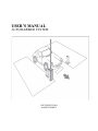
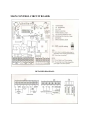
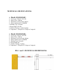
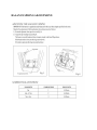
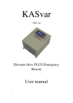
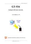
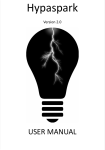
USER’S MANUAL
AUTO BARRIER SYSTEM
COPY RIGHTS 2009
MADE IN KOREA
SAFETY INSTRUCTION:
Before to proceed to barrier installation, please read this safety instruction
manual carefully to avoid any damage, or injury.
Please check if all accessories such as control box, boom, and main body of
barrier cabinet are free from any damage or physical defects.
During installation, make sure the main power is shut-off.
The cabinet body must be properly grounded.
We suggest using cable with minimum of 1.5mm2 or flat wires atleast gauge
16.
Do not dismantle the original wiring or set-up without proper noticed from
the distributor.
If during power fail off, please switch off the power supply first, then open
the cabinet and release the handle manually to open the barrier boom at top
position.
Please install the release button at secure area to avoid any accident. It
should be installed out of reach of children.
Do not operate the remote control if you cannot see the status of barrier.
Please secure the wireless remote control to secured area or designated
personnel only.
Please don’t open the cabinet door if the barrier is at working state.
The users must installed safety devices such as loop vehicle detector, or
photocells to avoid accidents. It is the responsibility of the clients since we
insist the safety devices at the start.
The client must inform the users to not stay at barrier drop zone area, and
must designate proper staying areas, and proper distance from the barrier.
The client will provide UPS or AVR to stabilize the power supply source to
avoid motor damage due to power fluctuation, surges currents, short circuit,
etc.
WIRELESS REMOTE CONTROL CODE SETTINGS:
Press “ Learn Button”, and the learn LED lights.
Press the button on the transmitter until the LEARN LED flash and off.
Coding is successful; please try the coded remote control to test it.
Please program other transmitter based on above procedure.
WIRELESS REMOTE CONTROL CODE DELETING:
Press “ Learn Button”, and hold on until the LEARN LED light switch off.
Now, deleting is successful.
WARRANTY:
The barrier is still under warranty if the following conditions
are still intact:
The warranty void sticker is not damage or altered;
There is no sign of mis-used, tampered, improper installation, damage caused by
fire, power interruption, surge current, riot, natural calamities and any acts of
Nature.
Kindly inform us not later than 7 days from the date of purchased, if found no
warranty sticker attached during acceptance of the purchased item/s. Any claim
outside that period is not covered and not entitled to any warranty parts &
services.
For details, you may contact the authorized agent/distributor, “HI-R Technology
and Service Co.”
DISTRIBUTOR INFORMATION:
HI-R Technology and Service Co.
2nd Floor Alba Bldg., Km. 21 West Service Road,
Cupang, Muntinlupa City
Email: [email protected]
Tel. No.: 02-7722766/65
Contact: Technical Department
MAIN CONTROL CIRCUIT BOARD:
DETAILED DIAGRAM:
TECHNICAL SPECIFICATIONS:
Model: HI-R 805AB3
Power type: 220VAC 50/60 Hz
Motor Power: 90Watts
Maximum accessory loads: 200mA
Motor rotation speed: 2,800RPM
Running Type: 3seconds
Boom length: 3M /4M
Number of spring: 1 spring/2 springs
Temperature: -20 degrees to 70 degrees Centigrade
Model: HI-R 805AB6
Power type: 220VAC 50/60 Hz
Motor Power: 90Watts
Maximum Accessory loads: 200mA
Motor rotation speed: 2,800RPM
Running Type: 6 seconds
Boom length: 6M
Number of spring: 3 springs
Temperature: -20 degrees to 70 degrees Centigrade
FIG.1 and 2 -TECHNICAL DIEMENSIONS:
BALANCE SPRING ADJUSTMENT:
QUICK RELEASE FUNCTIONS:
During power failure, and in the absent of UPS or back-up power, you need to switch off the
main switch and release the lever manually up to TOP or vertical position, then Lock it, and once
the power is back, please switch on the main switch and the barrier boom automatically goes
down at normal state. Please see Fig.5
All limit switches, motor, and control unit are already connected and only photocell, loop
detector, and power supply AC source are needed for the proper installation as shown below: