1
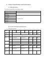
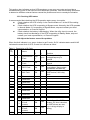
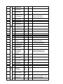
TABLE OF CONTENTS IMPORTANT SAFETY INSTRUCTIONS SAVE THESE INSTRUCTIONS This manual contains important safety instructions. Read all safety and operating instructions before operating the uninterruptible power systems (UPS). Adhere to all warnings on the unit and in this manual. Follow all operating and user instructions. This equipment can be operated by individuals without previous training. This products designed for commercial/industrial use only. It is intended for use with lift support and other designated “critical” devices. Maximum load must not exceed that shown on the UPS rating label. The UPS is designed for data processing equipment. If uncertain, consult your dealer or local representative. This UPS is designed for use on a properly grounded (earthed), 220/230/240VAC, 50 or 60Hz supply. The factory default setting is 220VAC/50Hz. Installation instructions and warning notices are in this manual. The IST3 6/10@220/230/240VAC is designed for use with a three-wire input (L,N,G). The IST4 10/15/20@220/230/240VAC is designed for use with a five-wire input (A,B,C,N,G). WARNING The battery can present a risk of electrical shock and high short circuit current. Following precautions should be observed before replacing the battery. Wear rubber gloves and boots. Remove rings, watches and other metal objects. Use tools with insulated handles. Do not lay tools or other metal objects on the batteries. If the battery is damaged in any way or shows signs of leakage, contact your local representative immediately. Do not dispose of batteries in a fire. The batteries may explode. Handle, transport and recycle batteries in accordance with local representative. WARNING Although the HT11/31 has been designed and manufactured to ensure personal safety, improper use can result in electrical shock or fire. To ensure safety, observe the following precautions: Turn off and unplug the HT11/31 before cleaning it. Clean the UPS with a dry cloth. Do not use liquid or aerosol cleaners. Never block or insert any objects into the ventilation holes or other openings of the UPS. Do not place the HT11/31 power cord where it might be damaged. 1. Electromagnetic Compatibility Safety IEC/EN 62040-1-1 EMI Conducted Emission.........IEC/EN 62040-2 Radiated Emission............IEC/EN 62040-2 EMS ESD..................................IEC/EN 61000-4-2 RS....................................IEC/EN 61000-4-3 EFT..................................IEC/EN 61000-4-4 SURGE............................IEC/EN 61000-4-5 Low Frequency Signals IEC/EN 61000-2-2 Warning: This is a product for commercial and industrial application in the second environment-installation restrictions or additional measures may be needed to prevent disturbances. NOTICE This is a product for restricted sales distribution to informed partners. Installation restrictions or additional measures may be needed to prevent radio interference. Operated the UPS in an indoor enviroment only in an ambient temperature range of 040C(32-104F). Install it in a clean environment, free form moisture, flammable liquids, gases and corrosive substance. This UPS contains no user-serviceable parts except the internal battery pack. The UPS on/off push buttons do not electrically isolate internal parts. Under no circumstance attempt to gain access internally, due to the risk of electric shock or burn. Do not continue to use the UPS if the panel indications are not in accordance with these operating instructions or the UPS performance alters in use. Refer all fault to your dealer. Servicing of batteries should be performed or supervised by personnel knowledgeable of batteries and the precautions. Keep unauthorized personnel away form the batteries. Proper disposal of batteries is required. Refer to your local laws and regulations for disposal requirement. DO NOT CONNECT equipment that could overload the UPS or demand DC current from the UPS, for example: electric drills, vacuum cleaners, laser printers, hair dryer or any appliance using half-wave rectification. Storing magnetic media on top of the UPS may result in data loss or corruption. Turn off and isolate the UPS before cleaning it. Use only a soft cloth, never liquid or aerosol cleaners. 2. Introduction Congratulations on your choice of the HT11/31 uninterruptible power system(UPS), the IST3/IST4 comes in nominal power ratings of 6000VA,10000VA,15000VA and 20,000VA. It is designed to provide conditioned power to microcomputers and other sensitive electronic equipment. When it is generated, alternating current is clean and stable. However, during transmission and distribution it may be subject to voltage sags, spikes and complete power failure that may interrupt computer operations, cause data loss and even damage equipment. The IST3/IST4 protects equipment form these disturbances. The IST3/IST4 is a compact, on-line UPS. An on-line UPS continuously conditions and regulates its output voltage, whether utility power is present or not. It supplies connected equipment with clean sinewave power. Sensitive electronic equipment operates best from sinewave power. For ease of use, the IST3/IST4 features a LCD display to indicate all information for UPS, and provide kinds of function buttons. 3. System Description 3.1 Transient Voltage Surge Suppression (TVSS) and EMI/FRI Filters These UPS components provide surge protection and filter both electromagnetic interference (EMI) and radio frequency interference (RFI). They minimize any surge or interference present in the utility line and keep the sensitive equipment protected. 3.2 Rectifier/Power Factor Correction (PFC) Circuit In normal operation, the rectifier/power factor correction (PFC) circuit converts utility AC power to regulated DC power for use by the inverter while ensuring that the wave shape of the input current used by the UPS is near ideal. Extracting this sinewave input current achieves two objects: The utility power is used as efficiency as possible by the UPS. The amount of distortion reflected on the utility is reduced. This results in cleaner power being available to other devices in the building not being protected by the IST3/IST4. 3.3 Inverter In normal operation, the inverter utilize the DC output of the power factor correction circuit and inverters it into precise, regulated sinewave AC power. Upon a utility power failure, the inverter receives its required energy from the battery through the DC-to-DC converter. In both modes of operation, the UPS inverter is on-line and continuously generating clean, precise, regulated AC output power. 3.4 Battery Charger The battery charger utilizes energy form the utility power and precisely regulates it to continuously float charge the batteries. The batteries are being charged whenever the IST3/IST4 is connected to utility power. 3.5 DC-to-DC Converter The DC-to-DC converter utilizes energy from the battery system and raises the DC voltage to the optimum operating voltage for the inverter. The converter includes boost circuit which is also used as PFC. 3.6 Battery The IST3 6-10K include value-regulated, nonspillable, lead acid batteries inside. To maintain battery design life, operate the UPS in an ambient temperature of 15-25C. 3.7 Dynamic Bypass The IST3/IST4 provides an alternate path for utility power to the connected load in the unlikely event of a UPS malfunction. Should the UPS have an overload, overtemperature or any other failure condition, the UPS automatically transfers the connected load to bypass. Bypass operation is indicated by an audible alarm and illuminated amber Bypass LED. To manually transfer the connected load from the inverter to bypass, press the ON/OFF button or Manual Bypass button once. NOTE The bypass power path does NOT protect the connected equipment from disturbances in the utility supply. 4. Product Specification and Performance 4.1 Model Description This manual is applicable to the following models: Model No. Type IST31060 Standard IST31100 IST31060-L IST31100-L Long backup time IST4100 IST4150 IST4200 4.2 Product Specification and Performance 1) General Specification Model IST31060 IST31060-L IST31100 IST31100- IST4100 L IST4150 IST4200 Power Rating 6KVA/5.4KW 15KVA/ 13.5KW 20KVA/ 18KW Frequency (Hz) 50/60 Input Voltage Output (304-478) (304-478) (304-478) VAC VAC VAC Current 34A max. 57A max 19A max 28.5A max 38A max Voltage 192VDC 192VDC 192VDC 192VDC 192VDC Current 37A max 60A max 60A max 90A max 120A max 45/43/42A 45/43/42 A 68/65/63 A 91/87/83 A 250*526*480 250*526*640 250*526* 640 250*544*750 Voltage 220/230/240VAC Current 27/26/25A Dimension (WxDxH) mm Weight (kg) 10KVA / 9KW (176-276)VAC (176-276)VAC Battery 10KVA/9KW 250*526*480 250*526*640 2) Electrical Performance Input Model Voltage Frequency Power Factor IST3 6-10K Single-phase 40-70Hz >0.99 (Full load) IST4 10/15/20K Three-phase 40-70Hz >0.95 (Full load) Output Voltage Regulation +-1% Power Factor 0.9 lag Frequency tolerance 0.1% of normal Distortion THD<1% Full load (Linear Load) Overload capacity 110% load: transfers to Bypass mode after 60 minutes 111%-130% load: transfers to Bypass mode after 1 minute 150% load :transfers to Bypass mode after 0.5 minute and shutdown the output after 1 minute 3) Operating Environment Temperature Humidity Altitude Storage temperature 0°C-40°C <95% <1000m 0°C-70°C NOTE If the UPS is installed or used in a place where the altitude is above than 1000m, the output power must be derated in use, please refer to the following: Altitude (M) 1000 1500 2000 2500 3000 3500 4000 4500 5000 Derating 100% 95% 91% 86% 82% 78% 74% 70% 67% Power 5. Installation The system should be installed and wired only by qualified electricians in accordance with applicable safety regulations. NOTE UPS operation in sustained temperature outside the range of 15-25°C (59°-77°F) reduces battery life. 5.1 Unpacking and Inspection 1) Unpack the packaging and check the package contents. The shipping package contains: ● 1 UPS ● 1 user manual ● 10 terminators for IST3 6-10K and IST4 2) Inspect the appearance of the UPS to see if there is any damage during transportation. Do not turn on the unit and notify the carrier and dealer immediately if there is any damage or lacking of some parts. 5.2 Connect Input/Output Power 1. Notes for installation 1) The UPS must be installed in a location with good ventilation, far away from water, inflammable gas and corrosive agents. 2) Ensure the air vents on the front and rear of the UPS are not blocked. Allow at least 0.5m of space on each side. 3) Condensation to water drops may occur if the UPS is unpacked in a very low temperature environment. In this case it is necessary to wait until the UPS is fully dried inside out before proceeding installation and use. Otherwise there are hazards of electric shock. 2. Installation Installation and wiring must be performed in accordance with the local electric code and the following instructions by professional personnel. For safety, please cut off the mains power switch before installation. Open the battery breaker for long backup time model (“L” model). 1) Open the terminal block cover located on the rear panel of the UPS, please refer to the appearance diagram. 2) For IST3 6K UPS, it is recommended to select the UL1015 10AWG(6mm2) wire or other insulated wire which complies with AWG Standard for the UPS input and output wirings. 3) For IST3 10K/IST4 10K UPS, it is recommended to select the UL1015 8AWG(10mm2) wire or other insulated wire which complies with AWG Standard for the UPS input and output wirings. 4) For IST4 15K and IST4 20K UPS, it is recommended to select the UL1015 6AWG(25mm2) wire or other insulated wire which complies with AWG Standard for the UPS input and output wirings. NOTE: Do not use the wall receptacle as the input power source for the UPS, as its rated current is less than the UPS’s maximum input current. Otherwise the receptacle may be burned and destroyed. For the long backup time modes, make sure that the capacity of batteries is larger than 24AH to avoid over charging. 5) Connect the input and output wires to the corresponding input and output terminals according to the following diagram. NOTE: You must make sure that the input and output wires and the input and output terminals are connected tightly 6) The protective earth ground wire refers to the wire connection between the equipment which consumes electric equipment and the ground wire. The wire diameter of protective earth ground wire should be at least as above mentioned for each model and green wire or green wire with yellow ribbon wire is used. 7) After having completed the installation, make sure the wiring connection is correct. 8) Please install the output breaker between the output terminal and the load, and the breaker should with leakage current protective function if necessary. 9) To connect the load with the UPS, please turn off all the loads first, then perform the connection and finally turn on the loads one by one. 10) No matter the UPS is connected to the utility power or not, the output of the UPS may have electricity. The parts inside the unit may still have hazardous voltage after turning off the UPS. To make the UPS have no output, power off the UPS, and then disconnect the utility power supply. 11) Suggest charging the batteries for 8 hours before use. After connection, turn the input breaker in the “ON” position, the UPS will charge the batteries automatically. You can also use the UPS immediately without charging the batteries first, but the backup time may be less than the standard value. 12) If it is necessary to connect the inductive load such as a monitor or a laser printer to the UPS, the start-up power should be used for calculating the capacity of the UPS, as its start-up power consumption is too big when it is started. 5.3 Operating procedure for connecting the long backup time model UPS with the external battery 1. 2. 1) 2) 3) The nominal DC voltage of external battery pack is 192VDC. Each battery pack consists of 16 pieces of 12V maintenance free batteries in series. To achieve longer backup time, it is possible to connect multi-battery packs, but the principle of “same voltage, same type” should be strictly followed. For HT31 15L/20L, select the UL1015 6AWG(25mm2) wire or other insulated wire which complies with UL Standard for the UPS battery wirings. The procedure of installing battery bank should be complied with strictly. Otherwise you may encounter the hazardous of electric shock. A DC breaker must be connected between the battery pack and the UPS. The capacity of breaker must be not less than the data specified in the general specification. Set the battery pack breaker in “OFF” position and connect the 16 pieces of batteries in series. You must connect the external battery cable to the battery first, if you connect the cable to the UPS first, you may encounter the hazardous of electric shock. The positive pole of the battery is connected to the UPS with red wire; the negative pole of the battery is connected to the UPS with black wire; the green and yellow ribbon wire is connected to the ground of the battery cabinet. 3. To complete the connection of the external battery cable into the UPS. Do not attempt to connect any loads to the UPS now. You should connect the input power wire to the right position first. And then set the breaker of the battery pack in the “ON” position. After that set the input breaker in the “ON” position. The UPS begins to charge the battery packs at the time. 5.4 Parallel operation 1. Brief introduction As long as the UPS is equipped with parallel cables, up to 3 UPSs can be connected in parallel to realize output power sharing and power redundancy. 2. Parallel installation 1) Users need to opt two standard 15-pin communication cables which length is appropriate to be less than 3m. 2) Strictly follow the stand-alone wiring requirement to perform the input wiring of each UPS. 3) Connect the output wires of each UPS to an output breaker panel. 4) Each UPS need an independent battery pack. 5) Please refer to the wiring diagram in the next page, and opt suitable breaker. ■ The requirement of the output wiring is as follows: ● When the distance between the UPSs in parallel and the breaker panel is less than 20 meters, the difference between the wires of input & output of the UPSs is required to be less than 20%. ● When the distance between the UPSs in parallel and the breaker panel is greater than 20 meters, the difference between the wires of input & output of the UPSs is required to be less than 10%. The wiring diagram are shown as follows: 3. Operation 1) To perform the general operation, follow the stand-alone operating requirement. 2) Startup: The units transfer to INV mode simultaneously as they start up sequentially in Line mode. 3) Shutdown: the units shut down sequentially in INV mode. When the last one completes the shutdown action, each unit will shut down the inverter simultaneously and transfer to Bypass mode. It is easy to operate the equipment, with no previous training. You just need to read through this manual and operate according to the instructions in it. 6. Controls and Indicators Table 1. Description of Panel Controls ON/OFF HOME ENTER Indicators STATUS REC INV BYP BAT OUTPUT Description 1.Press on/off to start inverter when rectifier is OK NOTE Not available when UPS is set in automatically start mode 2.Press on/off directly when there is no main input, press again to start UPS 3.Press on/off to shutdown inverter when UPS is in normal mode. 4.Press on/off to shutdown UPS completely when UPS is in battery mode Back to main menu Left and right Press to choose Description UPS status: green--normal mode, red--UPS is abnormal Rectifier indicator: green--rectifier is normal, green flicker--rectifier is starting, red--rectifier fault, red flicker--rectifier alarm, dark— rectifier is not working Inverter indicator: green--inverter is normal, green flicker--inverter is starting or tracking with bypass(ECO), red—inverter fault, red flicker—output is on inverter, inverter fault, dark—inverter is not working Bypass indicator: green—bypass is normal, dark—UPS is in normal mode and bypass is normal, red—bypass fault, red flicker —bypass alarm Battery indicator: green—battery charge, green flicker—battery discharge, dark—battery is connected, red—battery fault, red flicker—battery alarm Output indicator: green—output is normal, red—output alarm Table 2. Description of Main Menu Display Function Input information Battery information Output information Status of UPS Set and function History log Rated capacity: 10KVA 1phase in/out: 1/1 Input voltage Battery voltage and capacity remained Output voltage and load percent System working mode: P-parallel mode, 2-unit NO.2 Mute on, mute off Submenu Main input: voltage, current, frequency, PF Bypass input: Voltage, current, frequency, PF Battery: voltage, discharge current, battery status, battery temperature, capacity DCbus voltage Output information: Voltage, current, frequency, PF Load information: Active power, apparent power, percent Alarms, S-code, firmware version, system information Set: language, contrast, communication set(SNT, Modbus), Modbus set Function: function 1(transfer to bypass/escape, fault clear, mute on/off), function 2(battery test, maintenance test, stop test) / / / / / S--single mode, E--ECO mode 7. Operation 7.1 Operation Mode 1. Turn on the UPS in normal mode 1) 2) After you make sure that the power supply connection is correct, and then close the battery breaker (this step only for long backup time model), after that close the input breaker. At this time the fans rotate and the UPS operates in Bypass mode. After REC led is ready green, pressing the ON/OFF button continuously for more than 1 second, then choose YES to enter, the INV green led flickers. NOTE: In some application, UPS is set to start automatically, this step is not need. 3) About 1 minute later, the UPS turn into normal Line mode. If the utility power is abnormal, the UPS will operate in Battery mode without output interruption of the UPS. 2. Turn on the UPS from battery without utility power 1) 3) After you make sure that the breaker of the battery pack is in the “ON” position (this step only for long backup time model). Press the ON/OFF button once to power on the LCD, then press ON/OFF button again, choose YES to enter A few seconds later, the UPS turns into Battery mode. 3. Turn off the UPS in normal mode 1) Press ON/OFF button in condition of normal mode, then choose YES to transfer to bypass. Open the input breaker to turn off utility power supply, then open the battery breaker to turn off UPS completely. 2) 2) 4. Turn off the UPS in Battery mode 1) To power off the UPS by pressing the ON/OFF button continuously for more than 1 second, then choose YES. When being powered off, the UPS will turn into No Output mode. Finally not any display is shown on the display panel and no voltage is available from the UPS output. 2) NOTE Please turn off the connected loads before turning on the UPS and turn on the loads one by one after the UPS is working in INV mode. Turn off all of the connected loads before turning off the UPS. 7.2 Parallel Operation 1. Parallel Machine Maintenance This UPS system has parallel machine function, if you want to add single machine to parallel system, please follow operational process of joining new machine; if you must remove UPS, please follow operational processes of removing parallel machine. 2. How to install a new parallel UPS system: 1) Before installing a new parallel UPS system, user need to prepare the input and output wires, the output breaker, and the parallel cables. 2) Open the input and output breakers of each UPS. Connect the input wires, output wires and battery wires. 3) Connect each UPS one by one with the parallel cables. 4) Close the battery breakers and the input breakers of all of the UPSs in the parallel system in turn. 5) Turn on each UPS in turn and observe their display. Make sure that each UPS displays normal and all the UPSs transfer to the INV mode normally. 3. How to remove a single UPS from the parallel system: 1) If you need to remove one UPS of the UPSs parallel system which is on normal running, press the ON/OFF button of the UPS that is confirmed to be removed continuously and the UPS will cut off its output immediately. 2) Turn off the input breaker, the external mains input breaker, the output breaker and the battery breaker. 3) Press the others UPSs’s ON/OFF button. All of them transfer to the Bypass mode. 4) Remove the parallel cables of the UPS that need to be removed. 5) Press ON/OFF button of remained UPSs, then press YES to make the UPSs transfer to INV output. 8. Battery Maintenance IST3/IST4 series UPS only requires minimal maintenance. The batteries used for standard models are value regulated, sealed lead-acid, maintenance free battery. When being connected to the utility power, whether the UPS is turned on or not, the UPS keeps charging the batteries and also offers the protective function of overcharging and over-discharging. The UPS should be charged once every 4 to 6 months if it has not been used for a long time. In the regions of hot climates, the battery should be charged and discharged every 2 months. The standard charging time should be at least 12 hours. Under normal conditions, the battery life lasts 3 to 5 years. In case if the battery is found in bad condition, earlier replacement should be made. Battery replacement should be performed by qualified personnel. Replace batteries with the same number and same type of batteries. Do not replace the battery individually. All the batteries should be replaced at the same time following the instructions of the battery supplier. 9. Notes for Battery Disposal and Battery Replacement Procedures 9.1 Battery Disposal 1) Before disposing of batteries, remove jewellery, watches and other metal objects. 2) Use rubber gloves and boots, use tools with insulated handles. 3) If it is necessary to replace any connection cables, please purchase the original materials from the authorized distributors or service centers, so as to avoid overheat or spark resulting in fire due to insufficient capacity. 4) Do not dispose of batteries or battery packs in a fire. The batteries may explode. 5) Do not open or mutilate batteries, released electrolyte is highly poisonous and harmful to the skin and eyes. 6) Do not short the positive and negative of the battery electrode, otherwise, it may result in electric shock or fire. 7) Make sure that there is no voltage before touching the batteries. The battery circuit is not isolated from the input potential circuit. There may be hazardous voltage between the battery terminals and the ground. 8) Even though the input breaker is disconnected, the components inside the UPS are still connected with the batteries, and there are potential hazardous voltages. Therefore, before any maintenance and repairs work is carried out, switch off the breaker of the battery pack or disconnect the jumper wire of connecting between the batteries. 9) Batteries contain hazardous voltage and current. Battery maintenance such as the battery replacement must be carried out by qualified personnel who are knowledgeable about batteries. No other persons should handle the batteries 9.2 Battery Replacement Procedures 1) Press ON/OFF button to transfer to bypass mode 2) Switch the maintenance switch from UPS to Manual BYP 3) Remove both side covers from the UPS. 4) Disconnect the battery wires one by one. 5) Remove metal bars which are used to fasten batteries. 6) Replace batteries one by one. 7) Screw metal bars back to UPS. 8) Connect the battery wires one by one. Take care of electrical shock while connecting the last wire. 10. Trouble Shooting This section describes checking the IST3/IST4’s status. This section also indicates various UPS symptoms a user may encounter and provides a troubleshooting guide in the event the UPS develops a problem. Use the following information to determine whether external factors caused the problem and how to remedy the situation. 10.1 Checking UPS status It recommended that checking the UPS operation status every six months. Check whether the UPS is faulty: Is the Fault Indicator on? Is the UPS sounding an alarm? Check whether the UPS is operating in Bypass mode. Normally, the UPS operates in Normal Mode. If it is operating in Bypass Mode, stop and contact your local representative, or Channel Support. Check whether the battery is discharging. When the utility input is normal, the battery should not discharge. If the UPS is operating in Battery Mode, stop and contact your local representative, or Channel Support. 10.2 Adjust the factors caused the problem When the fault indicator is on, press button to get S-code. So,S1 indicates status and A0-A5 indicates the exact fault of UPS, S-code list is shown as follow: Table 3. Description of S-Code S eq Items . 1 A Synchronous 0 1 Fault 2 0 Syn c 1 Not sync . Faul t 2 Main Input Fault OK 3 REC Fault OK Faul t 4 INV Fault OK Faul t 5 6 5 Reserved 6 Reserved 7 8 7 Reserved 8 Reserved 9 10 9 1 0 1 1 1 2 Reserved OK Faul t OK Faul t OK Faul 3 4 11 12 13 14 15 1 3 1 4 1 Solution Check whether bypass voltage/frequency is normal Check whether input is normal REC overtemperature, bus overvoltage, input current unbalance, soft start fail INV overtemperature, INV IGBT broken, INV relay fault Reserved Reserved Reserved Input phase A over current Input phase B over current Input phase Check if rectifier IGBT is broken, DC bus is shorted, or IGBT drivers are lost, input voltage display is wrong 5 C over current 1 6 Output voltage Fault 17 18 1 Reserved 2 Reserved 19 20 3 Reserved 4 Reserved 21 22 5 Reserved 6 Reserved 23 24 7 Reserved 8 Reserved Input voltage Fault Input Frequency Fault Input Sequence Fault 16 25 9 26 27 A 1 28 1 0 1 1 1 2 29 1 3 1 4 30 REC softstart Fault t OK Faul t Check if inverter IGBT is broken, IGBT drivers are lost OK Faul t Input voltage out of range OK Faul t Input frequency out of range OK Faul t OK Faul t OK Faul t Reserved Reserved 31 32 33 34 35 36 A 2 1 5 REC over temperature 1 6 Positive bus over voltage Negative bus over voltage 1 2 Fan Fault 3 Reserved 4 Reserved Positive bus under voltage Negative bus under voltage Battery reversed Reserved Reserved 37 5 38 6 39 40 41 7 8 9 Input sequence is wrong, check whether input wires connection is ok. Check whether rectifier SCR is broken, or SCR drivers are lost. OK OK OK Faul t Faul t Faul t Check if the environmental temperature is over 40, if rectifier IGBTs is properly installed. UPS requires service UPS requires service At least one of fans fail. OK Faul t UPS requires service OK Faul t UPS requires service OK Faul t Check if the battery wires connection is OK 42 1 0 1 1 1 2 43 44 45 1 3 46 1 4 1 5 1 6 47 48 49 Reserved Reserved Reserved Battery over temperature Battery EOD 52 4 Reserved 53 54 5 Reserved 6 Reserved BYP voltage Fault Bypass SCR or relay fault Reserved 55 7 56 57 58 8 A 3 9 1 0 59 1 1 60 1 2 1 3 1 4 1 5 1 6 61 62 63 64 65 66 A 4 OK Faul t Faul t Faul t Check if bypass input voltage is normal OK Faul t Check if bypass input frequency is abnormal OK Faul t OK OK BYP frequency over track range Reserved Reserved Over load time out Reserved Reserved Manual shutdown nor mal 2 INV protect OK 3 4 UPS requires service. Reserved 1 67 68 Faul t Reserved 3 51 OK Check if environmental temp is too high or batteries life is over Reserved 2 50 Faul t Reserved Battery voltage low Reserved 1 OK Transfer times limit in one hour Reserved OK shut dow n Faul t Faul t Transfer times between inverter and bypass is over 5 times in one hour 69 70 5 Reserved 6 Reserved 71 7 Reserved INV over temperature Fault Reserved 72 8 73 74 9 1 0 OK Faul t Reserved 75 1 1 76 1 2 1 3 77 78 1 4 79 80 81 82 83 84 A 5 1 5 1 6 1 OK Over load INV relay or fuse Fault OK Faul t OK Faul t Check whether parallel connection cable disconnect. OK Faul t Shutdown UPS and open output breaker, check if load is effective or short internally, check if output connector is shorted. OK 2--Fault OK 2--Fault Reserved Parallel connection fault Reserved Reserved Reserved 2 3 Battery test 85 86 5 Battery maintenance Reserved 6 Reserved 87 88 7 Reserved 8 Reserved 89 90 9 1 0 1 1 1 2 1 3 1 4 1 5 Reserved 91 92 93 94 95 Check load level indicator and remove non-essential load. Recalculate the load and remove number of loads connected to UPS. Check if inverter relay is shorted or opened. Over load Output shorted 4 Check if environmental temp is over 40C, or fans are abnormal Reserved Reserved Reserved Reserved Reserved Reserved Non e Non e 96 1 6 Reserved Annex 1. Dry Contact Remote EPO Input Port The UPS has an Emergency Power OFF (EPO) function. This function can be activated through a remote contact provided by the user. J2 is the input port for remote EPO. It requires shorting NC and +24v during normal operation, and the EPO is triggered when opening NC and +24v, or shorting NO and +24v. The port diagram is shown in fig 10, and port description is shown in table 4. Table 4. Description of Input Port for Remote EPO Position Name Purpose J2.1 EPO_NC EPO is activated when disconnecting fromJ2.2 J2.2 +24V +24V, connect the common terminal of NC and NO J2.3 EPO_NO EPO is activated when shorting with J2.2 External Bypass Dry Contact Port UPS provides a port J3 for external maintenance bypass breaker status. It can be activated when external bypass breaker is closed. The port diagram is shown as fig 11, and port description is shown as table 5. Table 5. Description of Input Port for General Input Signal Position Name Purpose J3.1 +24V +24V power supply J3.2 INPUT_SIGNAL External bypass breaker control signal J3.3 GND Power ground Battery Low Alarm Output Dry Contact Port J4 is a dry contact port for battery low alarm, when the battery voltage is low, the UPS will provide an auxiliary dry contact signal via isolation of relay. The diagram is shown as fig 12, and description is shown as table 6. Table 6. Description of Battery Low Alarm Dry Contact Port Position Name Purpose Battery low alarm, relay(normally closed) will be J4.1 UTI_FAIL_NC open during warning Battery low alarm, relay (normally open) will be J4.2 UTI_FAIL_NO closed during warning J4.3 GND GND General Alarm Dry Contact Port J5 is the general alarm dry contact port. When one or more than one present alarm is trigged, J5 will provide an isolated signal via a relay. The diagram of general alarm dry contact is shown as fig 13. And description of J5 is shown as table 7. Table 7. Description of General Alarm Dry Contact Port Position Name Purpose Integrated warning relay (normally closed) will be J5.1 ALARM_NC open during warning Integrated warning relay (normally open) will be J5.2 ALARM_NO closed during warning J5.3 GND Centre of integrated warning relay Utility Fail Alarm Dry Contact Port J6 is the output dry contact interface for utility failure alarm, when the utility fails, the system will send an alarm signal, and provides an auxiliary dry contact signal via the isolation of relay. The interface diagram is shown in fig 14, and description is shown in table 8. Table 8. Description of Utility Fail Alarm Dry Contact Port Position Name Purpose Utility failure warning relay(normally closed) will be J6.1 UTI_FAIL_NC open during warning Utility failure warning relay (normally open) will be J6.2 UTI_FAIL_NO closed during warning J6.3 GND GND