1
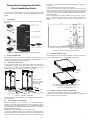
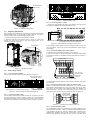
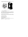
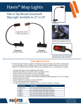
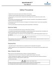
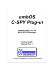
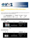
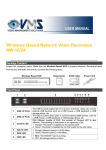
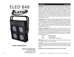
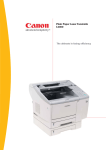
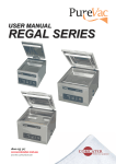
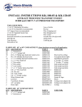
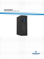
SmartCabinet
SmartCabinet Quick Installation Guide
SmartCabinet Integrated Solution
Quick Installation Guide
This document has been created as a Quick Installation Guide only and
should be read in conjunction with the SmartCabinet Integrated Solution User
Manual
1
Overview
The appearance and the components of the SmartCabinet are shown in
Figure 1-1.
the requirement on distance from the inlet and outlet side of the outdoor unit
to the wall.
2. Use expansion bolts to fix the outdoor unit to the base.
3. Connect the copper pipes (included in the accessory box) to the Indoor and
Outdoor components. Follow industry standards in selection and placement
of pipe, system evacuation and if required, charge with additional refrigerant.
This should only be required if the length of pipeworks exceeds the length of
the supplied pipework.
Note: If Condensing Unit is positioned beside the Smart Cabinet, it may be
easier to break the pipework through the side panels. Grommets and
Vapour sealing will be required inb this instance but Warranty will not be
voided.
Figure 2-2 Normal installation of the outdoor unit
Figure 1-1 Appearance and components of the SmartCabinet
2
2.3 Installing MSC-C Card
Quick Installation
After the product arrives, follow this quick installation guide for operation. If
you want to know specific descriptions and detailed installation diagram, refer
to SmartCabinet Integrated Solution User Manual.
Insert the MSC-C card into the intellislot intelligent card slot of the UPS, and
use the provided screws to fix it in place, as shown in Figure 2-3.
2.1 Installing Cabinet Kit
1. Loosen the fixing nuts on the four feet bolts to raise the feet, and the four
casters will bear the weight. Place a slope (user-provided) in front of the front
or rear door, and connect it to the pallet. Push the cabinet slowly from the
pallet down to the ground along the slope, as shown in Figure 2-1.
Intelligent
card slot
Push the cabinet
slowly from the pallet
down to the ground
along the slope
Place a slope
and connect it
with the pallet.
MSC-C
intelligent
card
Note: For Asia-Pacific version, the MSC-C intelligent
card has already been installed before delivery.
Figure 2-3 Installing MSC-C card
Pallet
Pallet
Baffle plate
of intelligent
card slot
Slope
Figure 2-1 Remove from the pallet
2.4 Installing Wireless Modem (Optional)
1. Connect the wireless Modem to the USB port of the MSC-C card.
2. Position the wireless Modem aerial that contains magnet on the bottom
plate in hot aisle, as shown in Figure 2-4.
2. Place the cabinet in the desired position, and adjust the feet fixing nuts until
the cabinet is level.
2.2 Air Conditioner Installation
Mechanical Installation will be required by your preferred Mechanical
Contractor to install the outdoor Condensing Unit and pipework for the air
conditioner. There are two installation types: For Cabinet-Top installation,
specific descriptions and detailed installation diagrams, refer to SmartCabinet
Integrated Solution User Manual.
For Remote mounting and connection of the Condensing Unit:
1. Confirm the installation position of the outdoor unit on site and place on
cutomer supplied base or mounting brackets. Emerson recommends the use
of rubber anti-vibration mounts or waffle pad (no supplied). See Figure 2-2 for
1
UPS
+
Intellislot
Paralleled address
Wireless Modem
MSC-C card
Battery port
192Vdc 27A
Input switch
230/400Vac-40A
PE
Battery module
Control port
Figure 2-7 Connecting battery cable
Aerial
2.6.3
Connecting MSC-C Cable
1. Connect the cable W08B to the COM1 port of MSC-C card, and connect
the cable W12 (COM2) to the COM2 port of MSC-C card.
Figure 2-4 Installing wireless Modem
2.5 Adjusting Microswitch
Before shipping, the microswitch on the front & rear doors are retracted back
into the cabinet and do not contact with the doors, therefore, you need to
adjust the position of the microswitch before startup in field.
LAN USB COM1COM2
W12 COM2
W08B COM1
1. Loosen the two fixing screws on the microswitch metal kit.
2. Adjust the metal kit to the direction shown in Figure 2-5, ensure that
opening and closing of the front & rear doors triggers action of the
microswitch, as shown in Figure 2-5.
Communication wiring
MSC-C
UPS
+
PE
UPS输入\UPS INPUT
UPS输出\UPS OUPUT
Note: For Asia-Pacific version, the MSC-C cables
have already been connected before delivery.
Figure 2-8 Cable connection of COM port of MAC-C card
A
Microswitch kit
2. Use a straight network cable to connect the LAN port of MSC-C card to the
user local network, and you can monitor the SmartCabinet system through
the Wed page.
2.6.4
Connecting Mains Input Cable System
1. Press and connect OT terminal (accessory) on the cable end.
2. Open the cover plate on the back of the PMU, connect the supplied cable
to the total input position on the PMU connecting terminal block, as shown in
Figure 2-9.
电源管理单元/PMU
PDU
A amplified
Fixing
screw
(2 pcs)
空调\AC
PE PE
Figure 2-5 Adjusting microswitch
L
N
总输入\Main Input
L
N
PE
UPS输出\UPS Output UPS输入\UPS Input
2.6 Connecting Cables
Connecting UPS Cables
L
N
PE
PE
L
N
Connect input and output cables of the UPS, as shown in Figure 2-6.
External total
input cable
UPS-provided shorting
line (line No.: W01)
3. Place the cable into the cable entry hole of mains input cable, and restore
the cover plate.
2.6.5
Indoor terminal block
Take out battery cable A from the UPS accessory kit, connect the red, black
and yellow terminals on the end of battery cable A with the corresponding
terminals of the battery port on the rear panel of the UPS, and connect the
other end with any battery port on the battery module, as shown in Figure 2-7.
Connecting cable
between indoor
and outdoor unit
2
Connecting battery cable
Outdoor connecting
terminal
2.6.2
1
Figure 2-6 Cable connection for single-in and single-out
N
N L
PE PE L N
Input W01 Output W02
PE
Note: For Asia-Pacific version, the UPS cables
have already been connected before delivery.
Connecting Cables of A/C Indoor & Outdoor Units
Install the provided Signal and Power cables (shown in Fig 2.10 but provided
as 2 separate cables) between the indoor and outdoor units via the cable
entry hole on the cover plate. Power Cables will need to be installed by a
licenced Electrician. Connect to the corresponding terminal studs on the
indoor and outdoor units according to the labels, as shown in Figure 2-10.
2
Control port
1
PE
L
Battery port
192Vdc 27A
N
Input switch
230/400Vac-40A
Figure 2-9 Connecting total input cable
PE
+
Intellislot
Paralleled address
Cable entry hole
of total input cable
L
2.6.1
Figure 2-10 Connecting power cable to outdoor unit
2.6.6
Connecting Earth Cable
Your SmartCabinet is earthed via the Electrical Input cable installed by your
licenced electrical contractor. There is no need for a separate earth input but
if the installation requires one, there is a separate earth connection point,
complete witrh penetration and grommet at the bottom of the enclosure.
When earthing seperatley, use a M6 screw to fix one end of the earth cable
2
via the earth hole, and lead the other end through the rubber grommet on the
bottom plate to the earth copper bar, as shown in Figure 2-11.
Earth hole
Screw
Cabinet
A
A amplified
Figure 2-11 Connecting earth cable
3
Startup Operation
Once the Electrical and Mechanical Installation of your SmartCabinet has
been completed, contact your local Emerson Authorised Service Provider
(ASP) to arrange Commissioning and Start-up prior to switching on your
system. Faiulure to have the system checked by Emerson or our ASP’s
could render the manufacturer’s warranty void
Emerson or our ASP’s will also be respoinsible for any ongoing recommended
Maintenance Regime’s to ensure the optimum performance and prolonged
oiperation of your SmartCabinet.
Emerson Network Power Australia
Suite A, Level 6, 15 Talavera Road
Macquarie Park NSW 2113
www.emersonnetworkpower.com
Copyright © 2014 by Emerson Network Power Co., Ltd.
All rights reserved. The contents in this document are subject to change
without notice.
Version V1.1A
Revision date June 19th, 2015
3
About Emerson Network Power
Emerson Network Power, a business of Emerson (NYSE:EMR), is the
world’s leading provider of critical infrastructure technologies and
life cycle services for information and communications technology
systems. With an expansive portfolio of intelligent, rapidly deployable
hardware and software solutions for power, thermal and infrastructure
management, Emerson Network Power enables efficient, highlyavailable networks. Learn more at www.EmersonNetworkPower.asia
Emerson Network Power Asia Pacific HQ
29/F Orient Square Bldg
F. Ortigas Jr. Road
Pasig City 1600, Philippines
Tel. No.: +63 2 620 3600
Australia
Head Office
Level 6, 15 Talavera Rd, Macquarie Park
NSW 2113, Australia
Tel No.: +61 2 9914 2900
Queensland
Unit 3, 50 Borthwick Ave, Murarrie, QLD 4172
Australian Capital Territory
Unit 5, 164 Gladstone St, Fyshwick, ACT 2609
Victoria
Unit 11, 350 Bridge St, Port Melbourne, VIC
3207
Western Australia
Unit 3, 10 Main Street, Osborne Park, WA 6017
Toll-Free No.: 1800 005 161
New Zealand
Auckland
2/14 Burleigh St, Grafton, Auckland 1023
Tel. No.: +64 9 443 5495
Christchurch
Unit 10/9 Print Place, Middleton,
Christchurch 8024
Tel. No.: +64 3 339 2060
Stay connected:
EmersonNetworkPower.eu
While every precaution has been taken to ensure accuracy and completeness herein, Emerson Network Power assumes no responsibility, and disclaims all liability, for damages resulting from
use of this information or for any errors or omissions. Specifications are subject to change without notice. Emerson Network Power and the Emerson Network Power Logo are trademarks of
Emerson Electric Co. or one of its affiliated companies. All other names and logos referred to are trade names, trademarks, or registered trademarks of their respective owners.
©2015 Emerson Electric Co. All right reserved. FY15ENT_Liebert80exl_V1_BR