1
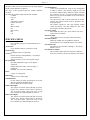
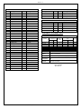
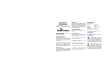
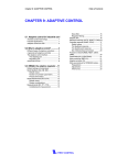
PC78 - 1
PC78
Intelligent Motion Controller for PC/104 or RS-232
FEATURES
Controller capabilities
٠ Four axes of stepper control with encoder
feedback or servo
٠ Encoder feedback to 12MHz
Communications
٠ PC/104 bus
٠ Stand-alone with RS-232 port
٠ Interrupt or polling communication
٠ 4 I/O registers for control & status
Sophisticated Control Functionality
٠ 16 bit DAC analog resolution
٠ Independent and coordinated motion of all axes
at the same time
٠ Slip & Stall detection with encoder feedback
٠ Crystal controlled step pulse from 0 to
1,044,000 steps per second
٠ Circular interpolation
٠ Constant velocity linear interpolation (all axes)
٠ Electronic gearing
32 bit Processor for Extensive Co-Processing
٠ Does not burden the host with overhead
٠ Custom, parabolic, cosine, linear trajectory
profiles
٠ Patented technology to minimize torque ripple
and velocity modulation
٠ Internal watchdog timer for safety
Control signals
٠ Single high density shielded SCSI3 connector
٠ Up to 12 user I/O
٠ Motion Control Output is +/-10V or 0-10V Servo or
Step & Direction
٠ Dedicated home and plus / minus over-travel inputs
for each axis
OMS - EZ™ Software programming
٠ High level programming expertise not required
٠ Over 150 commands, “universal” to all Pro-Dex,
Inc. controllers
٠ Commands are ASCII characters
٠ Capable of conversion to “user” defined units i.e.
inches / revolutions
٠ Software for WIN95/98, NT, 200 and XP.
٠ Software supplied at no additional cost
Flash Memory
٠ Field upgradeable firmware within Windows
operating systems
٠ Non-volatile program storage and parameter storage
Flexible and Expandable
٠ Conforms 100% to all PC/104 specifications
٠ Customizable solutions available for your
requirements
Factory Direct Technical Support
٠ Person to person toll-free tech support:
call 800-707-8111
٠ Application notes and Documentation on the Web
٠ Example programs and application code provided
٠ All Pro-Dex, Inc. controls are 100% tested and
quality inspected
CERTIFIED TO
ISO 9001
Tel: (503)629-8081or (800)707-8111
Fax: (503)629-0688 or (877)629-0688
WEB SITE: www.pro-dex.com
PRO-DEX. INC. - OREGON MICRO SYSTEMS, INC.
Beaverton, Oregon
PC78 - 2
DESCRIPTION
COMMAND SUMMARY
The PC78 is both a PC/104 controller that supports the
PC/104 ISA bus standard as well as a stand-alone controller
via a RS-232 communication port and is compatible with the
PC68 family with 2-4 axes control. The PC78 supports up to
12 general purpose TTL I/O bits, 8 of which are user
definable.
This section contains a sampling of some of the commands
available on the PC78.
The step pulse is a TTL level 50% duty cycle square wave
that supports velocities of 0 through 1,044,000 pulses per
second.
The encoder feedback functionality supports
quadrature encoders up to 12 MHz at a 4 times the encoder
line resolution and is used as closed-loop feedback for the
stepper axes or as independent position feedback. The
encoder feedback can provide slip and/or stall detection.
Each axis includes dedicated +/- overtravel inputs, a home
input, and an auxiliary output.
PROGRAMMING
PC78 motion controllers are easily programmed with double
character ASCII commands through an extensive command
structure. The commands are combined into character strings
to create sophisticated motion profiles and are passed to the
PC78 data I/O register. A separate ‘FIFO’ command queue
for each axis is used to store the parsed commands by the
PC78 until they are executed allowing the host to send a
complex command sequence and attend to other tasks while
the PC78 manages the motion process. These command
queues store 200 command and parameter words and include
a command loop counter which allows multiple executions of
any command string.
The following commands are available in the PC78 family of
motion controllers. All commands are sent to the controller
as ASCII character strings. Some commands expect one or
more numerical operands to follow. These commands are
identified with a ‘#’ after the command. The ‘#’ indicates a
signed integer input parameter or a signed fixed point number
of the format ##.# when user units are enabled. With user
units defined, distances, velocity and acceleration parameters
may be input in inches, revolutions, etc.∗
Synchronized moves may be made by entering the AA or AM
command. This command performs a context switch which
allows entering commands of the format MRx#,y#,z#,t#;.
Numbers are entered for each axis which is to be commanded
to move. An axis may be skipped by entering the comma
with no parameter. The command may be prematurely
terminated with a “;”, i.e. a move requiring only the X and Y
axes would use the command MRx#,y#; followed by the GO
command. Each axis programmed to move will start together
upon executing the GO command. The PC78 can be switched
back to the unsynchronized mode by entering the desired axis
command such as AX.
∗
The user manual has all commands listed and should be used
to program the Motion Controller.
PRO-DEX. INC. - OREGON MICRO SYSTEMS, INC.
AXIS SPECIFIC COMMANDS:
AA
AXIS ALL
Commands following the AA are directed to all axis queues for
synchronized mode.
AM
AXIS MULTITASKING
Commands following the AM will go into the specified axis
queues for independent synchronized mode.
AX
AXIS X
The AX command directs all the following commands to the X
axis.
AY
AXIS Y
The AY command directs all the following commands to the Y
axis.
AZ
AXIS Z
The AZ command directs all the following commands to the Z
axis.
AT
AXIS T
The AT command directs all the following commands to the T
axis.
SYSTEM CONTROL COMMANDS
These commands allow control of various system parameters and
operating modes to allow the user to optimize the response of the
system for his/her application needs.
BI
BIPOLAR
The BI command sets the servo analog torque outputs to bipolar.
CN
COSINE ON
The CN command enables cosine velocity ramps i.e. half sinusoid
acceleration profiles for all axes.
EN
ECHO ON
The EN command enables echoing from the PC78.
EF
ECHO OFF
The EF command disables echoing from the PC78.
HH
HOME HIGH
The HH command sets the sense of the home switch on the current
axis to active high.
HL
HOME LOW
The HL command sets the sense of the home switch on the current
axis to active low.
LF
LIMITS OFF
The LF command turns off the limit switches for the addressed
axis. This allows the stage to move beyond the limit switch and
should be used with caution.
LH
LIMIT HIGH
The LH command sets the logic sense of the overtravel limit
inputs to active high.
Beaverton, Oregon
PC78 - 2
LL
LIMIT LOW
The LL command sets the logic sense of the overtravel limit
inputs to active low.
LN
LIMITS ON
The LN command restores the operation of the limit switches
for the addressed axis.
PF
PARABOLIC OFF
The PF command restores linear acceleration and deceleration
ramps.
PN#
PARABOLIC ON
The PN command enables parabolic ramps. The parameter
selects the point of truncation.
SB#
SET BAUD
The SB command sets the baud rate to the parameter
supplied.
SF
SOFT LIMIT OFF
The SF command restores the normal operation of the limit
switches.
SL
SOFT LIMIT
The SL command changes the operation of the limit inputs
causing the output pulse train to ramp down instead of
terminating immediately. The output queue is not flushed
except for the current move.
UN
UNIPOLAR
The UN command sets the servo analog torque outputs to
unipolar.
MOVE SPECIFICATION COMMANDS
These commands allow specification of move parameters.
They allow move parameters to be tailored to the user’s
system requirements.
AC#
ACCELERATION
The AC command sets the acceleration/deceleration value.
This value is used to establish the rate of acceleration and
deceleration when a move command is invoked.
LP#
LOAD POSITION
The LP command will immediately load the position supplied
as a parameter into the absolute position register of the axis.
RM# REMAINDER (MODULO)
The RM command will divide the position counter by the
parameter supplied and replace both the position counter and the
encoder position register with the resulting remainder. This
command is useful in continuously rotating axis applications.
VB#
VELOCITY BASE
The VB command allows the velocity ramp to start at the specified
velocity. This allows faster acceleration and the ability to pass
through resonance quickly in some applications.
VL#
VELOCITY
The VL command sets the maximum velocity value of the axis
being programmed. The value is used to establish the maximum
velocity when one of the move execution commands is invoked.
MOVE EXECUTION COMMANDS
These commands allow execution of the moves which have been
previously specified.
GD
GO AND RESET DONE FLAG
The GD command resets the done flags on the active axes then
proceeds with the move identical to the GO command.
GO
GO
The GO command will initiate the move which has been
previously programmed with such commands as MA, MR, MT,
and ML.
FL
FLUSH QUEUE
The FL command will immediately flush the command queue. If
the stage is moving it continues to move at the current velocity.
JF#
JOG FRACTIONAL VELOCITIES
The JF command will jog the current axis at fractional rates for
applications requiring very slow velocities.
JG#
JOG
The JG command is a velocity command and will jog the axis at
the velocity supplied as a parameter. The velocity may be
changed without stopping by entering another JG command.
MOVE TERMINATION COMMANDS
The following commands allow termination of move sequences in
process.
MA# MOVE ABSOLUTE
The MA command will set up the axis to move to the absolute
position supplied as a parameter.
KL
KILL
The KL command will flush the command queue and terminate
pulse generation of all axes immediately.
ML#,# MOVE LINEAR
The ML command uses linear interpolation to perform a
straight line relative move to the new location. Up to eight
axes may be moved together in the AA or AM modes.
SA
STOP ALL
The SA command flushes all queues and causes all axes to
decelerate to a stop at the rate previously specified in an AC
command.
MR# MOVE RELATIVE
The MR command will set up the axis to move relative from
the current position at the time the move is executed.
SD
STOP AND RESET DONE
The SD command will stop all axes and clear any done flags.
MT#,# MOVE TO
The MT command uses linear interpolation to perform a
straight line move to the specified absolute position. Up to
eight axes may be moved together in the AA or AM modes.
ST
STOP
The ST command flushes the queue for the currently addressed
axis only and causes the axis to decelerate to a stop at the rate
previously specified in an AC command.
PRO-DEX. INC. - OREGON MICRO SYSTEMS, INC.
Beaverton, Oregon
PC78 - 3
LOOP CONTROL COMMANDS
These commands allow move sequences to be repeated within
loops. Loops can be nested up to four levels deep on each
axis.
LE
LOOP END
The LE command terminates the most recent LS command.
LS#
LOOP START
The LS command sets the loop counter for the axis being
programmed. The parameter specifies the number of times
the loop will be executed. Loops may be nested up to 4 levels
deep.
The following commands can be used to synchronize multiple
PC78 boards or synchronize them to external events.
CW
CLEAR WHILE
The CW command terminates the WH command sequence
upon execution of the next WG instruction. This loop is
always executed at least once.
WD
WHILE END
The WD command serves as the loop terminator for the WS
command.
WG
WHILE FLAG END
The WG command serves as the terminator for the WH
command.
WH
WHILE
The WH command will execute all commands until the
terminating WG command as a loop, until terminated by a
CW command. This allows indefinite loops to be terminated
by the host computer.
WS#
WHILE SYNC TRUE
The WS command will execute the commands between the
WS and WD commands as a loop, while the general purpose
input line is true, i.e. low. The test is at the bottom of the loop
and thus will always be executed at least once.
HOME AND INITIALIZATION CONTROL
COMMANDS
These commands allow the coordination of the physical stage
home position with the PC78 position register.
HM# HOME
The HM command will find home and initialize the position
counter to the position supplied as a parameter.
KR
HOME REVERSE AND KILL
The KR command will find home in reverse and stop generating
pulses immediately, i.e. no deceleration ramp will be generated.
The position counter is not affected.
MOVE SYNCHRONIZATION COMMANDS
These commands allow the synchronization of moves with
external events or multiple axis sequences.
CA
CLEAR AXIS DONE FLAG
The CA command operates like the IC command, except it clears
the done flag of the addressed axis only.
IC
INTERRUPT CLEAR
The IC command will clear the done and error flags.
ID
INTERRUPT DONE
The ID command will return the done flag to the host and
interrupt the host if the interrupt has been enabled.
II
INTERRUPT INDEPENDENT
The II command allows each axis to interrupt the host when it
completes its move independent of the status of the other axes.
IN#
INTERRUPT NEARLY DONE
The IN command will interrupt the host when the move is nearly
complete. The parameter specifies the number of counts left in the
move when the interrupt request is generated.
SW#
SYNC WAIT
The SW command can be used to synchronize to external events
by commanding the PC78 to wait for the input line to go false.
WA
WAIT FOR AXES
The WA command, only valid in the AA mode, allows a
command to wait until all moves on all axes are finished before it
executes.
WQ
WAIT FOR QUEUE TO EMPTY
The WQ command is a special command that stops the board from
processing any new command until the queue for the current axis
mode is empty.
WT# WAIT TIME
The WT command will wait for the specified number of
milliseconds before proceeding with the next command.
SYSTEM STATUS REQUEST COMMANDS
These commands allow the host to request the status of various
move parameters, including the status of limit and home switches.
HR#
HOME REVERSE
The HR command will find home in the reverse direction and
initialize the position counter to the position supplied as a
parameter.
QA
QUERY AXIS
The QA command returns the status of the single addressed axis
like the RA command, except the status register and flags are not
affected.
KM
HOME AND KILL
The KM command will find home and stop generating pulses
immediately, i.e. no deceleration ramp will be generated. The
position counter is not affected.
QI
QUERY INTERRUPT STATUS
The QI command returns the status of all axes like the RI
command, except the status register and flags are not affected.
PRO-DEX. INC. - OREGON MICRO SYSTEMS, INC.
Beaverton, Oregon
PC78 - 4
RA
REPORT AXIS INTERRUPT STATUS
The RA command returns the state of the limit and home
switches, and the done and direction flags for the currently
addressed axis. The done flag is reset.
RC
REPORT ACCELERATION
The RC command will return the current programmed
acceleration or deceleration of the current axis.
RP
REPORT POSITION
The RP command requests the current position.
RI
REPORT INTERRUPT STATUS
The RI command returns the state of the limit and home
switches, and the done and direction flags for all axes. The
done flags are reset.
RQ
REPORT QUEUE STATUS
The RQ command returns the number of entries available in
the command queue.
RU
REPORT POSITION IN USER UNITS
The RU command returns the current position in user units.
AN
AUXILIARY ON
The AN command sets the auxiliary output to the high level. The
open collector driver is off allowing the output to be pulled high
by a pull-up resistor. It may be used to change power level on
driver modules so equipped or as a user specified output.
BH#
BIT HIGH
The BH command sets the selected general purpose output off, i.e.
logic high.
BL#
BIT LOW
The BL command sets the selected general purpose output on, i.e.
logic low.
BX
REPORT I/O BIT STATE
The BX command returns the state of the general purpose I/O bits
in hex format.
PA#
POWER AUTOMATIC
The PA command will perform an AN command at the beginning
of each move and an AF command after the move. See AN and
AF commands.
RV
REPORT VELOCITY
The RV command will return the current velocity at which the
axis is moving.
SE#
SETTLING TIME
The SE command allows specification of a settling time, in
milliseconds, to be used before the power is reduced, when using
the PA mode.
WY
WHO ARE YOU
The WY command returns the model and firmware revision
of the board or system being addressed.
RB
REPORT I/O BIT DIRECTION
The RB command returns the direction of the general purpose I/O
lines as they are currently defined in hex format.
USER UNIT COMMANDS
CONSTANT VELOCITY CONTOURING COMMANDS
The following commands allow specification of move
parameters in user defined units. The Pro-Dex, Inc. controls
will automatically convert all move parameters to these units
once they have been initialized.
The contouring command set allows the building of a command
sequence which can later be executed at constant velocity for
machine tool and other similar applications.
UF
USER UNITS OFF
The UF command turns off user units and causes the PC78
board to use its default units.
AF#,# AUXILIARY OFF
The AF command turns off any combination of auxiliary ports,
when encountered in the command stream, allowing control of
other peripherals such as a laser beam for machining.
UU#
USER UNITS
The UU command converts all move velocities, distances, etc.
to user specified units by multiplying by the parameter given
in this command.
AN#,# AUXILIARY ON
The AN commands turns on any combination of auxiliary output
ports when encountered in the contouring command stream.
USER I/O COMMANDS
The following commands allow manipulation and testing of
the user definable I/O.
AF
AUXILIARY OFF
The AF command sets the auxiliary output to the low level.
The open collector driver is on causing the line to be near
ground. It may be used to change power level on driver
modules so equipped or as a user specified output.
PRO-DEX. INC. - OREGON MICRO SYSTEMS, INC.
CD#,#; CONTOUR DEFINE
The CD command allows entry of a contour definition which will
start at the position specified. Any combination of axes may be
used in the contour mode.
CE
CONTOUR END
The CE command ends the definition of the contour sequence, i.e.
terminate the CD mode or ramp to a stop and exit when the
contour is executed.
CK
CONTOUR END AND KILL
The CK command ends the definition of the contour sequence and
stops output generation immediately when executed.
Beaverton, Oregon
PC78 - 5
CR#,#,# CIRCULAR INTERPOLATION
The CR command causes the axes defined by the CD
command to move in a circular pattern from the entry
position. The parameters specify the center of the circle and
distance to travel in radians. The CR command is only valid
with contours of 2 axes.
CV#
CONTOUR VELOCITY
The CV command allows the specification of the contouring
velocity.
CX
CONTOUR EXECUTE
The CX command causes the PC78 controller to execute the
previously defined contour sequence.
MT#,# MOVE TO
The MT command causes the axes defined by the CD
command to move to the specified absolute position using
linear interpolation at constant velocity.
RQ
REQUEST QUEUE STATUS
The RQ command returns the number of entries available in
the contouring queue.
PID FILTER CONTROL COMMANDS
The following commands set the PID filter parameters
KA# ACCELERATION FEEDFORWARD
COEFFICIENT
The KA command sets the acceleration feedforward
coefficient on servo axes.
KD#
DIFFERENTIAL GAIN COEFFICIENT
The KD command sets the differential gain coefficient on
servo axes.
KI#
INTEGRAL GAIN COEFFICIENT
The KI command sets the integral gain coefficient on servo
axes.
KO#
OFFSET COEFFICIENT
The KO command sets a DC offset to compensate for torque
offset in the load.
KP#
PROPORTIONAL GAIN COEFFICIENT
The KP command sets the proportional gain coefficient on
servo axes.
KV#
VELOCITY FEEDFORWARD COEFFICIENT
The KV command sets the velocity feedforward coefficient
on servo axes.
ENCODER COMMANDS
The following are encoder support commands for use with the
PC78.
HD#
HOLD DEADBAND
The HD command specifies deadband counts for position hold.
The PC78 will consider the control in position when the stage is
within the specified parameter counts during position correction.
HF
HOLD OFF
The HF command disables position hold, stall detection and
tracking modes.
HG#
HOLD FILTER PARAMETERS
The HG command specifies the gain for stepper applications with
feedback.
HN
HOLD ON
The HN command enables position correction.
HV#
HOLD VELOCITY
The HV command specifies maximum position hold correction
velocity. This is the peak velocity which will be used while
making position corrections.
IP
INTERRUPT WHEN IN POSITION
The IP command operates like the ID command, except the
interrupt is deferred until the stage is within the specified
deadband.
The following commands control the slip or stall detection mode
for stepper with encoder models of the PC78.
ES#
ENCODER SLIP TOLERANCE
The ES command parameter specifies tolerance before slip or stall
is flagged in the status register.
IS
INTERRUPT ON SLIP
The IS command will enable interrupts to the host when the
position error during a move exceeds the parameter specified by
an ES command. The interrupt will occur if the done interrupt has
been enabled in the control register. A bit in the status register is
also set to flag the source of the interrupt.
TF
SLIP TOLERANCE KILL OFF
The TF command disables the TN command.
TN
SLIP TOLERANCE KILL ON
The TN command enables additional action taken by the encoder
slip tolerance system when the position error exceeds that
specified by the ES command. When this mode is on, the
controller will flush the command queue, terminate the motion, set
the slip flag and disable position maintenance for that particular
axis.
RL
RETURN SLIP STATUS
The RL command returns the slip detection status of each axis.
An S is returned if slip has occurred for that axis, or else an N is
returned.
The following are position maintenance control commands:
The following command controls the tracking mode of the
controls.
ER#,# ENCODER RATIO
The ER command allows specification of encoder ratio by
entering encoder counts followed by motor counts, for
position maintenance mode. (for digital output only)
ET
ENCODER TRACKING
The ET command turns on tracking mode. The axis will track its
encoder input, allowing one axis to be manually positioned by any
device that produces a signal compatible to the encoder inputs.
PRO-DEX. INC. - OREGON MICRO SYSTEMS, INC.
Beaverton, Oregon
PC78 - 6
The following commands control the home sequence when
used with an encoder.
EA
ENCODER STATUS
The EA command returns the encoder status of the currently
addressed axis.
HE
HOME ENCODER
The HE command enables the encoder index mode, i.e. home
is defined as the logical AND of the encoder index, the
external home enable and the encoder quadrant.
HS
HOME SWITCH
The HS command enables non-encoder (switch only) home
mode.
The following commands return status information about the
encoder to the host.
RE
REQUEST ENCODER POSITION
The RE command returns the current encoder position of the
currently addressed axis in encoder counts.
VELOCITY STAIRCASE COMMANDS
The following commands describe the velocity staircase
mode. This mode is useful in applications requiring a change
in velocity at a prescribed position without stopping.
FP#
FORCE POSITION
The FP command will flush the command queue and attempt
to stop at the specified position.
MM
MOVE MINUS
The MM command sets the direction logic to move in the
negative direction.
MP
MOVE POSITIVE
The MP command sets the direction logic to move in the
positive direction.
MV#,# MOVE VELOCITY
The MV command causes the motor to run to the new
absolute position at the specified velocity. A velocity
staircase may be generated by queuing a sequence of MV
commands.
SP#
STOP AT POSITION
The SP command will cause the axis to stop at the specified
position.
MACRO CONTROL COMMANDS
MD# MACRO DEFINITION
The MD# command allows the user to combine several SRX
commands into one of 20 macros.
MX# MACRO EXECUTE
The MS command allows the user to execute a specified
macro.
PRO-DEX. INC. - OREGON MICRO SYSTEMS, INC.
PROGRAMMING EXAMPLES
In a typical move requirement where it is desired to home the
stage then move to a specified position, the following will
demonstrate the programming:
Initialize the velocity and acceleration parameters to a low value
suitable for homing. Set a PID filter proportional gain of 2 and a
derivative gain of 6. Perform the home operation initializing the
position counter to zero.
Initialize the velocity and acceleration parameters to perform a
faster motion and move to an absolute position of 10,000 counts
from home in the positive direction and set the done flag when
finished.
The following would be input from the host computer:
AX;
VL1000;
AC10000;
KP2;
KD6;
HN;
HM0;
VL5000;
AC50000;
MA10000;
GO;
ID;
In a move requiring a three axis coordinated move to a position in
free space the following could be used:
AX;
KP2;
KD6;
HN;
AY;
KP2;
KD6;
HN;
AZ;
KP2;
KD6;
HN;
AM;
VL5000,5000,5000;
AC50000,50000,50000;
MT1000,2000,3000;
GO;
ID;
The controller would calculate the relative velocities required to
perform a straight line move from the current position to the
desired position.
The following demonstrates cutting a hole with a 10,000 count
radius using constant velocity contouring and circular
interpolation:
The contouring velocity is set to 1000 counts per second. A
contour is defined beginning at coordinates 0,0 on the Z and T
axes.
Auxiliary output on the X axis is turned on, which could turn on
the cutting torch or laser starting the cut at the center of the circle.
A half circle is cut from the center to the outside of the hole
positioning the cutting tool at the start of the hole.
Beaverton, Oregon
PC78 - 7
The hole is then cut, the torch turned off, the stage stopped
and the contour definition completed.
The stage is then positioned and the contour definition
executed.
The following would be input from the host computer:
CV1000;
CD,,0,0;
AN0;
CR0,5000,3.1415926;
CR0,0,6.2831853;
AF0;
MT-10,10000;
CE;
MT,,-1000,0;
GO;
CX;
SPECIFICATIONS
Velocity
0 to 1,044,000 counts per second simultaneous on
each axis
Acceleration
0 to 8,000,000 counts per second per second
Position range
67,000,000 counts (±33,500,000)
Accuracy
Position accuracy and repeatability ±0 counts for
point to point moves
Velocity accuracy ±0.01% for step pulse output
Environmental
Operating temperature range: 0 to 50 degrees
centigrade
Storage temperature range: -20 to 85 degrees
centigrade
Humidity: 0 to 90% non-condensing
Power
+5VDC at 1 amp typical
Dimensions
3.550x3.775x0.5 inches high
Communication
PC/104: Meets all signal specifications for PC/104
ISA bus specifications (IEEE P996.1)
RS-232: Baud rates of 300 to 38.4K
Limit switch inputs
TTL input levels with on board 2.2K pull up resistor,
requires only external switch closure to ground or
TTL level input signal. Input sense (low or high
true) selectable by command input for each axis.
Home switch inputs
TTL input levels with on board 2.2K pull up resistor,
requires only external switch closure to ground or
TTL level input signal. Input sense (low or high
true) selectable by command input for each axis.
PRO-DEX. INC. - OREGON MICRO SYSTEMS, INC.
User definable I/O
12 bits of user definable I/O. 8 bits are user configurable
as inputs or outputs. One auxiliary output per axis and
are fixed as outputs. Factory default is 4 inputs, 4 outputs
and 1 auxiliary per axis. (For PC78 models with more
than 4 axes, up to twice this number of I/O in the same as
described above.)
TTL input levels with on board 2.2K pull up resistor,
requires only external switch closure to ground or TTL
level input signal.
The auxiliary outputs are TTL open collector outputs
(7406, max 48mA). The other outputs are TTL totem
pole outputs (74LS243, max 24mA).
Step pulse output
Pulse width 50% duty cycle. Open collector TTL level
signal (7406, max 48mA).
Direction output
Open collector TTL level signal (7406, max 48mA).
Encoder Feedback
Maximum 12 MHz after 4x quadrature detection
Differential TTL level signal MC26G32, max 150mA
PC/104 interrupt
Interrupts are user selectable, 2 through 7. The factory
default is level 5.
PC/104 bus I/O address
The I/O address block utilizes 4 consecutive addresses
and is user selectable. The factory default is 300-303 hex.
Beaverton, Oregon
PC78 - 8
Pin#
1
2
3
4
5
6
7
8
9
10
11
12
13
14
15
16
17
18
19
20
21
22
23
24
25
26
27
28
29
30
31
32
33
34
SIGNAL CONNECTOR (J5)
Description
Pin#
Description
Digital Ground
35
+5VDC
I/O 1
36
I/O 0
I/O 3
37
I/O 2
I/O 5
38
I/O 4
I/O 7
39
I/O 6
Digital Ground
40
+5VDC
X Index +
41
Reserved
X Index 42
X Step
X Phase A +
43
X Auxiliary
X Phase A 44
X Direction
X Phase B +
45
X Limit +
X Phase B 46
X Limit Reserved
47
X Home
Y Index +
48
Y Step
Y Index 49
Y Auxiliary
Y Phase A +
50
Y Direction
Y Phase A 51
Y Limit +
Y Phase B +
52
Y Limit Y Phase B 53
Y Home
Analog Ground
54
+5VDC
Z Index +
55
Reserved
Z Index 56
Z Step
Z Phase A +
57
Z Auxiliary
Z Phase A 58
Z Direction
Z Phase B +
59
Z Limit +
Z Phase B 60
Z Limit Reserved
61
Z Home
T Index +
62
T Step
T Index 63
T Auxiliary
T Phase A +
64
T Direction
T Phase A 65
T Limit +
T Phase B +
66
T Limit T Phase B 67
T Home
Digital Ground
68
+5VDC
PRO-DEX. INC. - OREGON MICRO SYSTEMS, INC.
POWER SUPPLY CONNECTOR (J3)
Description
Pin
Pin
Description
+5VDC
5
6
Digital Ground
-12VDC
3
4
N/C
+12VDC
1
2
Analog Ground
Description
Ground
DTR
TxD
RxD
N/C
RS-232 CONNECTOR (J4)
Pin
Pin Description
5
9
N/C
4
8
CTS
3
7
N/C
2
6
N/C
1
ORDERING INFORMATION
Pro-Dex, Inc. - PC78 Intelligent Motion Controls
MODEL
INTERFACE
PC/104
PC78-25
PC78-26
PC78-45
PC78-46
x
x
x
x
RS-232
x
x
x
x
SERVO
AXES
2
0
4
0
STEPPER
AXES
CONTROL
0
2
0
4
FEEDBACK
USER
I/O
0
2
0
4
12
12
12
12
ACCESSORIES
MODEL
DESCRIPTION
IO68-M
I/O Breakout board for standard or expansion PC78
motion control boards
CBL68-10
10 ft cable w/mating connector 68 pin, (IO68/PC78)
CDSWSUPP
CDMAN
DLLs and drivers for Windows NT, 95, 98, 2000 and
XP.
Electronic Manual 1 per shipment provided, unless
otherwise requested
3701-1400000
Revision A
Beaverton, Oregon
PC78 - 9
Actual Size Depiction below
0.200
0.125 Diameter
(Typical)
3.250”
J8
.300
J4
3.775”
FACTORY
USE
ONLY
J9
J3
J5
S1
S2
0.125 Diameter
(Typical)
J1
J2
0.200
0.200
3.550”
PRO-DEX. INC. - OREGON MICRO SYSTEMS, INC.
Beaverton, Oregon