1
SCXI
™
SCXI-1104/C User Manual
32-Channel Medium-Voltage Input Module
SCXI-1104/C User Manual
February 2000 Edition
Part Number 322147B-01
Worldwide Technical Support and Product Information
www.ni.com
National Instruments Corporate Headquarters
11500 North Mopac Expressway
Austin, Texas 78759-3504
USA Tel: 512 794 0100
Worldwide Offices
Australia 03 9879 5166, Austria 0662 45 79 90 0, Belgium 02 757 00 20, Brazil 011 284 5011,
Canada (Calgary) 403 274 9391, Canada (Ontario) 905 785 0085, Canada (Québec) 514 694 8521,
China 0755 3904939, Denmark 45 76 26 00, Finland 09 725 725 11, France 01 48 14 24 24,
Germany 089 741 31 30, Greece 30 1 42 96 427, Hong Kong 2645 3186, India 91805275406,
Israel 03 6120092, Italy 02 413091, Japan 03 5472 2970, Korea 02 596 7456, Mexico (D.F.) 5 280 7625,
Mexico (Monterrey) 8 357 7695, Netherlands 0348 433466, New Zealand 09 914 0488, Norway 32 27 73 00,
Poland 0 22 528 94 06, Portugal 351 1 726 9011, Singapore 2265886, Spain 91 640 0085,
Sweden 08 587 895 00, Switzerland 056 200 51 51, Taiwan 02 2528 7227, United Kingdom 01635 523545
For further support information, see the Technical Support Resources appendix. To comment on the
documentation, send e-mail to [email protected]
© Copyright 1998, 2000 National Instruments Corporation. All rights reserved.
Important Information
Warranty
The SCXI-1104 and SCXI-1104C modules are warranted against defects in materials and workmanship for a period of one year
from the date of shipment, as evidenced by receipts or other documentation. National Instruments will, at its option, repair or
replace equipment that proves to be defective during the warranty period. This warranty includes parts and labor.
The media on which you receive National Instruments software are warranted not to fail to execute programming instructions,
due to defects in materials and workmanship, for a period of 90 days from date of shipment, as evidenced by receipts or other
documentation. National Instruments will, at its option, repair or replace software media that do not execute programming
instructions if National Instruments receives notice of such defects during the warranty period. National Instruments does not
warrant that the operation of the software shall be uninterrupted or error free.
A Return Material Authorization (RMA) number must be obtained from the factory and clearly marked on the outside of
the package before any equipment will be accepted for warranty work. National Instruments will pay the shipping costs of
returning to the owner parts which are covered by warranty.
National Instruments believes that the information in this document is accurate. The document has been carefully reviewed
for technical accuracy. In the event that technical or typographical errors exist, National Instruments reserves the right to
make changes to subsequent editions of this document without prior notice to holders of this edition. The reader should consult
National Instruments if errors are suspected. In no event shall National Instruments be liable for any damages arising out of
or related to this document or the information contained in it.
EXCEPT AS SPECIFIED HEREIN, NATIONAL INSTRUMENTS MAKES NO WARRANTIES, EXPRESS OR IMPLIED, AND SPECIFICALLY DISCLAIMS ANY
WARRANTY OF MERCHANTABILITY OR FITNESS FOR A PARTICULAR PURPOSE. CUSTOMER’S RIGHT TO RECOVER DAMAGES CAUSED BY FAULT OR
NEGLIGENCE ON THE PART OF NATIONAL INSTRUMENTS SHALL BE LIMITED TO THE AMOUNT THERETOFORE PAID BY THE CUSTOMER. NATIONAL
INSTRUMENTS WILL NOT BE LIABLE FOR DAMAGES RESULTING FROM LOSS OF DATA, PROFITS, USE OF PRODUCTS, OR INCIDENTAL OR
CONSEQUENTIAL DAMAGES, EVEN IF ADVISED OF THE POSSIBILITY THEREOF. This limitation of the liability of National Instruments will
apply regardless of the form of action, whether in contract or tort, including negligence. Any action against National Instruments
must be brought within one year after the cause of action accrues. National Instruments shall not be liable for any delay in
performance due to causes beyond its reasonable control. The warranty provided herein does not cover damages, defects,
malfunctions, or service failures caused by owner’s failure to follow the National Instruments installation, operation, or
maintenance instructions; owner’s modification of the product; owner’s abuse, misuse, or negligent acts; and power failure or
surges, fire, flood, accident, actions of third parties, or other events outside reasonable control.
Copyright
Under the copyright laws, this publication may not be reproduced or transmitted in any form, electronic or mechanical, including
photocopying, recording, storing in an information retrieval system, or translating, in whole or in part, without the prior written
consent of National Instruments Corporation.
Trademarks
BridgeVIEW™, ComponentWorks™, CVI™, LabVIEW™, Measure™, National Instruments™, ni.com™, NI-DAQ™, RTSI™,
SCXI™, and VirtualBench™ are trademarks of National Instruments Corporation.
Product and company names mentioned herein are trademarks or trade names of their respective companies.
WARNING REGARDING USE OF NATIONAL INSTRUMENTS PRODUCTS
(1) NATIONAL INSTRUMENTS PRODUCTS ARE NOT DESIGNED WITH COMPONENTS AND TESTING FOR A LEVEL
OF RELIABILITY SUITABLE FOR USE IN OR IN CONNECTION WITH SURGICAL IMPLANTS OR AS CRITICAL
COMPONENTS IN ANY LIFE SUPPORT SYSTEMS WHOSE FAILURE TO PERFORM CAN REASONABLY BE
EXPECTED TO CAUSE SIGNIFICANT INJURY TO A HUMAN.
(2) IN ANY APPLICATION, INCLUDING THE ABOVE, RELIABILITY OF OPERATION OF THE SOFTWARE PRODUCTS
CAN BE IMPAIRED BY ADVERSE FACTORS, INCLUDING BUT NOT LIMITED TO FLUCTUATIONS IN ELECTRICAL
POWER SUPPLY, COMPUTER HARDWARE MALFUNCTIONS, COMPUTER OPERATING SYSTEM SOFTWARE
FITNESS, FITNESS OF COMPILERS AND DEVELOPMENT SOFTWARE USED TO DEVELOP AN APPLICATION,
INSTALLATION ERRORS, SOFTWARE AND HARDWARE COMPATIBILITY PROBLEMS, MALFUNCTIONS OR
FAILURES OF ELECTRONIC MONITORING OR CONTROL DEVICES, TRANSIENT FAILURES OF ELECTRONIC
SYSTEMS (HARDWARE AND/OR SOFTWARE), UNANTICIPATED USES OR MISUSES, OR ERRORS ON THE PART OF
THE USER OR APPLICATIONS DESIGNER (ADVERSE FACTORS SUCH AS THESE ARE HEREAFTER
COLLECTIVELY TERMED “SYSTEM FAILURES”). ANY APPLICATION WHERE A SYSTEM FAILURE WOULD
CREATE A RISK OF HARM TO PROPERTY OR PERSONS (INCLUDING THE RISK OF BODILY INJURY AND DEATH)
SHOULD NOT BE RELIANT SOLELY UPON ONE FORM OF ELECTRONIC SYSTEM DUE TO THE RISK OF SYSTEM
FAILURE. TO AVOID DAMAGE, INJURY, OR DEATH, THE USER OR APPLICATION DESIGNER MUST TAKE
REASONABLY PRUDENT STEPS TO PROTECT AGAINST SYSTEM FAILURES, INCLUDING BUT NOT LIMITED TO
BACK-UP OR SHUT DOWN MECHANISMS. BECAUSE EACH END-USER SYSTEM IS CUSTOMIZED AND DIFFERS
FROM NATIONAL INSTRUMENTS' TESTING PLATFORMS AND BECAUSE A USER OR APPLICATION DESIGNER
MAY USE NATIONAL INSTRUMENTS PRODUCTS IN COMBINATION WITH OTHER PRODUCTS IN A MANNER NOT
EVALUATED OR CONTEMPLATED BY NATIONAL INSTRUMENTS, THE USER OR APPLICATION DESIGNER IS
ULTIMATELY RESPONSIBLE FOR VERIFYING AND VALIDATING THE SUITABILITY OF NATIONAL
INSTRUMENTS PRODUCTS WHENEVER NATIONAL INSTRUMENTS PRODUCTS ARE INCORPORATED IN A
SYSTEM OR APPLICATION, INCLUDING, WITHOUT LIMITATION, THE APPROPRIATE DESIGN, PROCESS AND
SAFETY LEVEL OF SUCH SYSTEM OR APPLICATION.
Contents
About This Manual
Conventions ...................................................................................................................ix
Related Documentation..................................................................................................x
Chapter 1
Introduction
About the SCXI-1104/C Module ...................................................................................1-1
What You Need to Get Started ......................................................................................1-2
Unpacking ......................................................................................................................1-3
Custom Cable Components ...........................................................................................1-3
Chapter 2
Installation and Configuration
Installing the Software ...................................................................................................2-1
Installing the SCXI-1104/C ...........................................................................................2-2
Installing the SCXI-1104/C Module into the SCXI Chassis ...........................2-2
Connecting the SCXI-1104/C to a DAQ Device for Multiplexed
Scanning in an SCXI Chassis .......................................................................2-3
Connecting the SCXI-1104/C to a DAQ Device for Multiplexed
Scanning in a PXI Combination Chassis......................................................2-5
Configuration and Self-Test...........................................................................................2-6
Auto-Detecting Modules .................................................................................2-7
Manually Adding Modules..............................................................................2-8
Configuring the SCXI-1104/C ........................................................................2-9
Self-Test Verification ......................................................................................2-10
Troubleshooting Self-Test Verification...........................................................2-10
Removing the SCXI-1104/C..........................................................................................2-11
Removing the SCXI-1104/C from an SCXI Chassis ......................................2-11
Removing the SCXI-1104/C from Measurement & Automation Explorer.....2-13
© National Instruments Corporation
v
SCXI-1104/C User Manual
Contents
Chapter 3
Signal Connections
Front Signal Connector.................................................................................................. 3-2
Front Signal Connector Signal Descriptions................................................... 3-3
Analog Input Signal Connections..................................................... 3-3
Rear Signal Connector................................................................................................... 3-4
Rear Signal Connector Descriptions ............................................................... 3-5
Analog Output Signal Connections .................................................. 3-6
Digital I/O Signal Connections......................................................... 3-6
Chapter 4
Programming
Channel Addressing....................................................................................................... 4-2
LabVIEW and the SCXI Channel String ........................................................ 4-2
LabVIEW and the Virtual Channel String ...................................................... 4-3
Multiplexed Scanning.................................................................................................... 4-4
C and Low-Level DAQ Functions ................................................................................ 4-4
Chapter 5
Theory of Operation
Functional Overview ..................................................................................................... 5-1
Functional Unit Description .......................................................................................... 5-2
Rear Signal Connector, SCXIbus Connector, and SCXIbus Interface ........... 5-2
Digital Control Circuitry ................................................................................. 5-2
Analog Circuitry and Front Signal Connector ................................................ 5-3
Analog Input Channels ..................................................................... 5-3
Analog Bus Switches........................................................................ 5-3
Chapter 6
Calibration
Overview ....................................................................................................................... 6-1
Calibration Procedure.................................................................................................... 6-1
Calibration Equipment Requirements ............................................................. 6-1
Gain and Offset Calibration ............................................................................ 6-2
SCXI-1104/C User Manual
vi
www.ni.com
Contents
Appendix A
Specifications
Appendix B
Common Questions
Appendix C
Technical Support Resources
Glossary
Index
Figures
Figure 2-1.
Figure 2-2.
Figure 2-3.
Installing the SCXI-1104/C Module .....................................................2-3
Connecting an SCXI Chassis to a DAQ Device....................................2-5
Removing the SCXI-1104/C .................................................................2-13
Figure 3-1.
Figure 3-2.
SCXI-1104/C Module Front Signal Connector Pin Assignments.........3-2
SCXI-1104/C Module Rear Signal Connector Pin Assignments..........3-4
Figure 5-1.
SCXI-1104/C Module Block Diagram..................................................5-1
Tables
Table 3-1.
SCXIbus to SCXI-1104/C Module Rear Signal Connector to
DAQ Device Pin Equivalencies ............................................................3-6
Table B-1.
Digital Signals on the SCXI-1104/C .....................................................B-3
© National Instruments Corporation
vii
SCXI-1104/C User Manual
About This Manual
This manual describes the installation, operation, and use of the SCXI-1104
family of modules. The SCXI-1104 family consists of the following
modules:
•
SCXI-1104
•
SCXI-1104C
The SCXI-1104/C modules are members of the National Instruments
Signal Conditioning eXtensions for Instrumentation (SCXI) Series that are
designed for use with National Instruments data acquisition (DAQ) devices.
These modules are designed for signal conditioning of medium-voltage
signals—30 VACrms, ±42 VACpeak, ±60 VDC. The SCXI-1104/C modules
have 32 differential analog input channels.
Conventions
The following conventions appear in this manual:
<>
Angle brackets that contain numbers separated by an ellipsis represent a
range of values associated with a bit or signal name—for example,
DBIO<3..0>.
♦
The ♦ symbol indicates that the following text applies only to a specific
product, a specific operating system, or a specific software version.
This icon denotes a note, which alerts you to important information.
This icon denotes a caution, which advises you of precautions to take to
avoid injury, data loss, or a system crash.
bold
Bold text denotes items that you must select or click on in the software,
such as menu items and dialog box options. Bold text also denotes
parameter names.
italic
Italic text denotes variables, emphasis, a cross reference, or an introduction
to a key concept. This font also denotes text that is a placeholder for a word
or value that you must supply.
© National Instruments Corporation
ix
SCXI-1104/C User Manual
About This Manual
monospace
Text in this font denotes text or characters that you should enter from the
keyboard, sections of code, programming examples, and syntax examples.
This font is also used for the proper names of disk drives, paths, directories,
programs, subprograms, subroutines, device names, functions, operations,
variables, filenames and extensions, and code excerpts.
monospace bold
Bold text in this font denotes the messages and responses that the computer
automatically prints to the screen. This font also emphasizes lines of code
that are different from the other examples.
SCXI-1104/C
Refers to both the SCXI-1104 and SCXI-1104C modules.
Related Documentation
The SCXI-1104/C User Manual is one piece of the documentation set for
your data acquisition system. You could have any of several types of
manuals, depending on the hardware and software in your system. Use the
manuals you have as follows:
SCXI-1104/C User Manual
•
SCXI Quick Start Guide— This document describes how to quickly
install and configure your SCXI module.
•
Getting Started with SCXI—This is the first manual you should read.
It gives an overview of the SCXI system and contains the most
commonly needed information for the modules, chassis, and software.
•
Your SCXI module user manuals—Read these manuals next for
detailed information about signal connections and module
configuration. They also explain in greater detail how the module
works and contain application hints.
•
Your DAQ hardware user manuals—These manuals have detailed
information about the DAQ hardware that plugs into or is connected to
your computer. Use these manuals for hardware installation and
configuration instructions, specification information about your DAQ
hardware, and application hints.
•
Software manuals—Examples of software manuals you may have are
the LabVIEW and LabWindows/CVI manual sets and the NI-DAQ
manuals. After you set up your hardware system, use either the
application software (LabVIEW or LabWindows) manuals or the
NI-DAQ manuals to help you write your application. If you have a
large and complicated system, review the software manuals before you
configure your hardware.
x
www.ni.com
About This Manual
•
Accessory installation guides or manuals—Consult these guides when
you are installing terminal blocks, cable assemblies, or other SCXI
accessories.
•
SCXI chassis manual—Read this manual to obtain chassis installation
instructions and maintenance information.
© National Instruments Corporation
xi
SCXI-1104/C User Manual
1
Introduction
This chapter describes the SCXI-1104/C modules, lists what you need to
get started, and explains how to unpack the module. A table at the end of
this chapter lists vendors who manufacture mating connectors for
developing custom cables.
About the SCXI-1104/C Module
The SCXI-1104/C modules are for signal conditioning medium-voltage
signals. The SCXI-1104/C has 32 differential analog input channels. Each
channel also has a divide-by-10 attenuator stage before the amplifier. You
can multiplex the SCXI-1104/C inputs to a single module output that drives
a DAQ device input channel.
♦
SCXI-1104
On each channel, the SCXI-1104 has a three-pole lowpass filter with a
2 Hz cutoff frequency to reject 60 Hz noise.
♦
SCXI-1104C
On each channel, the SCXI-1104C has a three-pole lowpass filter with a
10 kHz cutoff frequency.
Detailed specifications of the SCXI-1104/C modules are in Appendix A,
Specifications. Figure 5-1, SCXI-1104/C Module Block Diagram, shows a
block diagram of the SCXI-1104/C.
© National Instruments Corporation
1-1
SCXI-1104/C User Manual
Chapter 1
Introduction
What You Need to Get Started
To install, configure, and use your SCXI-1104/C, you will need the
following items:
❑ One of the following modules
–
SCXI-1104
–
SCXI-1104C
❑ SCXI-1104/C User Manual
❑ One of the following connectivity devices
–
SCXI-1300
–
BNC-2095
–
TBX-96
–
SCXI-1310
❑ One of the following software packages and its documentation
–
ComponentWorks
–
LabVIEW for Macintosh
–
LabVIEW for Windows
–
LabWindows/CVI for Windows
–
Measure
–
VirtualBench
❑ One of the following device drivers
–
NI-DAQ for Macintosh
–
NI-DAQ for PC Compatibles
❑ Your computer with an installed DAQ device
❑ An SCXI chassis with an AC power cord and the appropriate cable
assembly
❑ Small Phillips-head screwdriver
❑ 1/4 in. flathead screwdriver
SCXI-1104/C User Manual
1-2
www.ni.com
Chapter 1
Introduction
Unpacking
Your SCXI-1104/C module is shipped in an antistatic package to prevent
electrostatic damage to the module. Electrostatic discharge can damage
several components in the module. To avoid damaging the module, take the
following precautions:
•
Ground yourself using a grounding strap or by holding a grounded
object.
•
Touch the antistatic package to a metal part of your SCXI chassis
before removing the module from the package.
•
Remove the module from the package and inspect the module for loose
components or any other sign of damage. Notify National Instruments
if the module appears damaged in any way. Do not install a damaged
module into your SCXI chassis.
•
Never touch the exposed pins of connectors.
Custom Cable Components
To develop custom cables, consult the following table.
Signal
Connector
SCXI–1104/C
Connector
Mating
Connector
Cable
Rear
AMP Inc. 50-pin
male ribbon-cable
header
Electronic Products
Division/3M or T&B/Ansley
Corp. 50-position polarized
ribbon-socket female
connector
Electronic Products
Division/3M or
T&B/Ansley Corp.
50-conductor, 28 AWG
stranded ribbon cable
Front
Harting Electronik
Inc. 96-pin DIN C
male connector
AMP Inc. (right-angle pins)
or Panduit Corp.
(straight-solder pins) 96-pin,
polarized, DIN C female
connector
Not applicable
© National Instruments Corporation
1-3
SCXI-1104/C User Manual
2
Installation and Configuration
This chapter describes how to install and configure the SCXI-1104/C
module. The SCXI-1104/C is a jumperless module and requires no user
modifications. There is no need for the user to remove the module cover.
Note The SCXI-1104/C does not support ribbon-cabled multichassis SCXI systems. You
must use the SCXI-1346 multichassis adapter in a multichassis system.
Installing the Software
You can control the SCXI-1104/C in an application development
environment (ADE) using the NI-DAQ data acquisition device driver
software. The supported ADEs include LabVIEW, BridgeVIEW,
LabWindows/CVI, Visual Basic (ComponentWorks), C, and C++
environments. You can also use the SCXI-1104/C in conjunction with
VirtualBench and Measure. The following instructions describe the order
for installing the software for your SCXI-1104/C:
1.
Install your ADE if you have not already done so. National Instruments
ADEs have release notes containing software installation instructions.
2.
Install the appropriate version of NI-DAQ software. NI-DAQ version
6.5.1 or higher is required to configure and program your SCXI-1104
module. NI-DAQ version 6.7 or higher is required to configure and
program your SCXI-1104C module. If you do not have the correct
NI-DAQ version, you can either contact a National Instruments sales
representative or download the latest NI-DAQ version from the
National Instruments Web site, www.ni.com. See Appendix B,
Common Questions, for information on getting the latest version of
NI-DAQ.
© National Instruments Corporation
a.
If you have the required version of NI-DAQ, insert your National
Instruments NI-DAQ software CD into the CD-ROM drive.
b.
Click on the Install NI-DAQ Software option in the installation
window. The installer guides you through the rest of the
installation process.
2-1
SCXI-1104/C User Manual
Chapter 2
Installation and Configuration
Installing the SCXI-1104/C
The following section describes how to install your SCXI-1104/C for use
with SCXI chassis and National Instruments DAQ devices.
Installing the SCXI-1104/C Module into the SCXI Chassis
You need the following items to complete the installation:
•
SCXI-1104/C module(s)
•
SCXI chassis or PXI combination chassis
•
1/4 in. flathead screwdriver
To install your SCXI-1104/C module into the SCXI chassis, follow these
steps while referring to Figure 2-1:
SCXI-1104/C User Manual
1.
Turn off the computer that contains the DAQ device or disconnect it
from your SCXI chassis.
2.
Turn off the SCXI chassis. Do not insert the SCXI-1104/C module into
a chassis that is turned on.
3.
Insert the SCXI-1104/C into an open slot in the SCXI chassis. Gently
guide the module into the slot guides and push it to the back of the slot
until the front face of the module is flush with the front of the chassis.
4.
Insert any other SCXI modules into the remaining slots in the same
manner as described in step 3.
5.
Secure all the SCXI modules to the SCXI chassis using both
thumbscrews.
2-2
www.ni.com
Chapter 2
Installation and Configuration
®
1
SC
MA
IN
XI
FR
AM
E
2
3
1
SCXI Chassis Power Switch
2
SCXI Chassis Slots
3
SCXI Module Thumbscrews
Figure 2-1. Installing the SCXI-1104/C Module
To complete your SCXI-1104/C installation, follow the procedure in the
appropriate sections that follow.
Connecting the SCXI-1104/C to a DAQ Device for Multiplexed Scanning
in an SCXI Chassis
This configuration allows you to multiplex all 32 input channels of the
SCXI-1104/C into a single channel of your DAQ device. You need the
following items for this installation:
•
SCXI chassis with the SCXI modules installed
•
SCXI cable assembly, which consists of a cable adapter and a cable
•
An installed National Instruments DAQ device
•
1/4 in. flathead screwdriver
Consult your SCXI chassis documentation, other SCXI module
documentation, and DAQ device documentation for additional instructions
and warnings. Your SCXI-1104/C module and any other SCXI modules
© National Instruments Corporation
2-3
SCXI-1104/C User Manual
Chapter 2
Installation and Configuration
should already be installed in the chassis according to their installation
instructions.
You must select one of the analog input modules in the chassis to be the
cabled module, the module to which the SCXI cable assembly will be
connected. If the chassis contains at least one simultaneous sampling
module such as the SCXI-1140, SCXI-1530, or SCXI-1531 module, select
one of these modules to be the cabled module; otherwise, select one of the
remaining analog input modules. To connect the chassis to a DAQ device
for multiplexed operation, complete the following steps while referring to
Figure 2-2:
SCXI-1104/C User Manual
1.
Turn off the SCXI chassis and the computer that contains the DAQ
device.
2.
Insert the cable adapter into the back of the SCXI chassis aligned with
the module that is to be connected to the DAQ device. See the
installation guide for your cable assembly for more information.
3.
Connect the cable to the back of the cable adapter ensuring that the
cable fits securely.
4.
Connect the other end of the cable to the DAQ device that you will use
to control the SCXI system.
5.
Check the cable installation, making sure the connectors are securely
fastened at both ends.
6.
Turn on the SCXI chassis.
7.
Turn on the computer.
8.
If you have already installed the appropriate software, you are ready to
configure the SCXI-1104/C module(s) for multiplexed mode
operation. See Configuration and Self-Test in this chapter.
2-4
www.ni.com
Chapter 2
Installation and Configuration
4
1
2
®
3
1
2
DAQ Device
Cable
3
4
Cable Adapter
SCXI Chassis Power Switch
Figure 2-2. Connecting an SCXI Chassis to a DAQ Device
Connecting the SCXI-1104/C to a DAQ Device for Multiplexed Scanning
in a PXI Combination Chassis
This configuration allows you to multiplex all 32 channels of your
SCXI-1104/C into a single channel of your DAQ device in a combination
PXI chassis. You need the following items for this installation:
•
PXI combination chassis with the SCXI modules installed
•
National Instruments PXI-MIO DAQ device installed in the right-most
slot
Consult your PXI chassis documentation, other SCXI module
documentation, and DAQ device documentation for additional instructions
and warnings. You should have already installed your SCXI-1104/C
module and any other SCXI modules in the chassis according to their
© National Instruments Corporation
2-5
SCXI-1104/C User Manual
Chapter 2
Installation and Configuration
installation instructions. To use the SCXI-1104/C module in multiplexed
mode with a DAQ device in a PXI combination chassis, follow these steps:
1.
No cables are required between the SCXI-1104/C and DAQ device if
the National Instruments PXI DAQ device is installed in the right-most
slot. This device can be configured to control the SCXI system using
an internal bus that connects the PXI chassis to the SCXI chassis. If the
DAQ device for controlling the SCXI system is not installed in the
right-most slot of the PXI combination chassis, configure the system
as described earlier in Connecting the SCXI-1104/C to a DAQ Device
for Multiplexed Scanning in an SCXI Chassis.
2.
Turn on the SCXI chassis.
If you have already installed the appropriate software, you are ready to
configure the SCXI-1104/C for multiplexed mode operation.
Configuration and Self-Test
Run Measurement & Automation Explorer to configure and test your
SCXI-1104/C. If you need help during the configuration process, open the
Measurement & Automation Help file by selecting Help Topics from the
Help menu. Follow these steps to configure your SCXI system:
1.
Double-click the Measurement & Automation Explorer icon on
your desktop. Click the + next to the Devices and Interfaces icon.
If you have added new modules to an existing chassis, go to step 4.
If you inserted modules into an empty chassis, go to step 2.
SCXI-1104/C User Manual
2.
Add a new chassis to the configured Devices and Interfaces by
holding down the right mouse button on Devices and Interfaces and
selecting Insert. Select the appropriate chassis from the list box and
click OK.
3.
Configure the chassis by selecting a Chassis ID. This is an integer
value you choose to uniquely identify the chassis for programming and
scanning. Select the Chassis Address. This is needed to address the
chassis in a multichassis SCXI system. Unless you are using multiple
chassis with the same DAQ device, select a Chassis Address of zero,
which is the factory-default setting of all SCXI chassis. If you are
using multiple chassis, refer to your SCXI chassis user manual for
further information. For remote SCXI chassis, you also need to select
the Baud Rate and COM Port. After completing the chassis
configuration, click Next.
2-6
www.ni.com
Chapter 2
4.
Installation and Configuration
You now have the choice of automatically detecting which modules are
installed in the chassis or manually adding them.
•
If you have just added the chassis to Devices and Interfaces and
are using an E Series or 1200 DAQ device, you can automatically
detect the modules.
•
If the chassis was already listed in Devices and Interfaces, you
must add new modules manually.
Go to the appropriate section that follows to continue the software
configuration of your chassis.
Auto-Detecting Modules
If you selected auto-detect, your chassis must be connected to your DAQ
device, except in the case of a remote chassis, which must connect to the
computer using a serial port cable.
Before auto-detecting modules, do the four steps of the Configuration and
Self-Test section.
To auto-detect your SCXI module(s), follow these steps:
1.
Make sure the chassis power is turned on.
2.
Select Yes under Auto-Detect modules and click Next. If your chassis
is a remote SCXI chassis, go to step 4, otherwise go to step 3.
3.
Select your communication path and click Next. If modules were
detected, select the module connected to your DAQ device as your
communication path.
4.
Click Finish.
Your Measurement & Automation Explorer software should now recognize
your SCXI chassis and SCXI module(s). If the software did not recognize
your module(s), check your cable connections and retry auto-detecting or
try installing the modules manually before taking troubleshooting
measures. If the software recognized any module as an SCXI custom
module, you may be using the wrong version of NI-DAQ. See Appendix B,
Common Questions, for information on getting the latest version of
NI-DAQ.
© National Instruments Corporation
2-7
SCXI-1104/C User Manual
Chapter 2
Installation and Configuration
Manually Adding Modules
If you did not auto-detect your SCXI modules, you must add each of your
modules separately. If you are still in the Chassis Configuration window,
select No under Auto-Detect modules and click Finish. Use the following
steps to manually add modules:
1.
Display the list of devices and interfaces by clicking the + next to the
Devices and Interfaces icon.
2.
Locate the SCXI chassis in the list. Display the list of modules in the
chassis by clicking the + next to the Chassis icon.
3.
Right-click the appropriate installation slot and click Insert.
4.
Select the module installed in that slot and click Next. If the
appropriate module name does not appear on the list, you may be using
the incorrect version of NI-DAQ. See Appendix B, Common
Questions, for information on getting the latest version of NI-DAQ.
5.
Configure your module as follows:
a.
If the selected module is connected to a National Instruments
DAQ device, select that device by using the Connected to control.
If it is not, select none. If you want this DAQ device to control the
chassis, confirm that there is a check in the checkbox labeled This
device will control the chassis.
b.
Select the multiplexed scanning mode for your SCXI-1104/C by
using the Operating Mode control. Click Next.
c.
Review the gain and filter settings for all channels on the
SCXI-1104/C. Click Next.
d.
Select the accessory you are using with this module. When you
have completed configuration, click Finish.
If you need to manually install more SCXI-1104/C modules in your
chassis, repeat steps 3 through 5 to configure each module.
Your SCXI chassis and SCXI module(s) should now be configured
properly. If you need to change your module configuration, see the next
section, Configuring the SCXI-1104/C. If your configuration is complete,
test the system as described in Self-Test Verification in this chapter to
ensure your SCXI system is communicating properly with the DAQ device.
SCXI-1104/C User Manual
2-8
www.ni.com
Chapter 2
Installation and Configuration
Configuring the SCXI-1104/C
To configure your SCXI-1104/C after auto-detection, or to alter your
original configuration selections, you must use the configuration utility in
Measurement & Automation Explorer. Perform the following steps to
configure your SCXI-1104/C:
1.
Run Measurement & Automation Explorer by double-clicking its icon
on your desktop.
2.
Display the list of installed devices and interfaces by clicking the +
next to the Devices and Interfaces icon.
3.
Locate the SCXI chassis in the list. Display the list of modules in the
chassis by clicking the + next to the Chassis icon.
4.
Right-click on the SCXI-1104/C module you want to configure and
select Properties. Click on the General tab.
a.
If the module you are configuring is connected to a National
Instruments DAQ device, select that device by using the
Connected to control. If you want this DAQ device to control
the chassis, confirm that there is a check in the checkbox labeled
This device will control the chassis. If the module you are
configuring is not connected to a National Instruments DAQ
device, select none.
b.
Select the multiplexed scanning mode for your SCXI-1104/C by
using the Operating Mode control.
5.
Click on the Channel tab. Review the gain and filter settings for all
channels on the SCXI-1104/C.
6.
Click on the Accessory tab. Select the accessory you are using with
this module. When all of your configurations are completed, click OK.
Your SCXI chassis and SCXI module(s) should now be configured
properly. Test the system in the section that follows to ensure your SCXI
system is communicating properly with the DAQ device.
© National Instruments Corporation
2-9
SCXI-1104/C User Manual
Chapter 2
Installation and Configuration
Self-Test Verification
To test the successful configuration of your system, follow the steps that
follow after entering the Measurement & Automation Explorer utility:
1.
Verify the chassis is on and correctly connected to a DAQ device.
2.
Display the list of Devices and Interfaces by clicking the + next to the
Devices and Interfaces icon.
3.
From the list that appears, locate the chassis you want to test.
Right-click on the chassis and select Test.
4.
If the communication test is successful, a message The chassis has
been verified appears. Click OK.
Your SCXI system should now operate properly with your ADE software.
If the test did not complete successfully, see the following section for
troubleshooting steps.
Troubleshooting Self-Test Verification
If the preceding test did not verify your chassis configuration, take the
following steps to successfully complete system configuration:
1.
If you get the warning message Unable to test chassis at this
time, you have not designated at least one module as connected to a
DAQ device. Return to the Configuring the SCXI-1104/C section and
change the configuration of the cabled module in your system from
Connected to: None to Connected to: Device x.
2.
SCXI-1104/C User Manual
If you get the warning message Failed to find followed by the
module codes and the message Unable to communicate with
chassis, take the following troubleshooting actions.
a.
Make sure the SCXI chassis is on.
b.
Make sure the cable between the SCXI chassis and DAQ device is
properly connected.
c.
Inspect the cable connectors for bent pins.
d.
Make sure you are using the correct National Instruments cable
assembly.
e.
Test your DAQ device to verify it is working properly. See your
DAQ device user manual for more information.
2-10
www.ni.com
Chapter 2
Installation and Configuration
3.
If you get the warning message Failed to find, followed by
module codes and then the message Instead found: module with
ID 0Xxx, return to the Configuring the SCXI-1104/C section and make
sure the correct module is in the specified slot. Delete the incorrect
module as described in the Removing the SCXI-1104/C from
Measurement & Automation Explorer section and then add the correct
module as described in the Manually Adding Modules section.
4.
If you get the warning message Failed to find, followed by a
module code and then the message Slot x is empty, check to see
if the configured module is installed in the specified slot. If not, install
the module by referring to the previous section, Installing the
SCXI-1104/C Module into the SCXI Chassis. If the module is installed
in the correct slot, turn off the chassis, remove the module as specified
in Removing the SCXI-1104/C from an SCXI Chassis, and verify that
no connector pins are bent on the rear signal connector. Reinstall the
module as shown in Installing the SCXI-1104/C Module into the SCXI
Chassis, ensuring the module is fully inserted and properly aligned in
the slot.
5.
After checking the preceding items, return to the Self-Test Verification
section and retest your SCXI chassis.
If these measures do not successfully configure your SCXI system, see
Appendix B, Common Questions, for more information.
Removing the SCXI-1104/C
This section will show you how to remove the SCXI-1104/C from an SCXI
chassis.
Removing the SCXI-1104/C from an SCXI Chassis
Only a qualified person who has read and understands all the safety
information in this manual should remove an SCXI module, disconnect
signals, or remove the SCXI-1104/C from the chassis. You need the
following items to remove the SCXI-1104/C module:
•
SCXI chassis or PXI combination chassis with the SCXI-1104/C
module(s) installed
•
1/4 in. flathead screwdriver
© National Instruments Corporation
2-11
SCXI-1104/C User Manual
Chapter 2
Installation and Configuration
Consult the documentation for your SCXI/PXI chassis and accessories for
additional instructions and warnings. To remove the SCXI-1104/C module
from an SCXI chassis follow the steps that follow while referring to
Figure 2-3:
1.
If the SCXI-1104/C is the cabled module, disconnect the cable running
from the SCXI-1104/C to the DAQ device.
Read the safety information in the appropriate section that follows and in the
associated terminal block installation guide before adding or removing any signals from
the SCXI module or terminal block.
Caution
SCXI-1104/C User Manual
2.
Remove all signals from the terminal block connected to the
SCXI-1104/C.
3.
Remove any terminal blocks connected to the SCXI-1104/C.
4.
Turn off the SCXI chassis. Do not remove the SCXI-1104/C module
from a chassis that is turned on.
5.
Rotate the thumbscrews that secure the SCXI-1104/C to the chassis
counter-clockwise until they are loose, but do not completely remove
the thumbscrews.
6.
Remove the SCXI-1104/C by pulling steadily on both thumbscrews
until the module slides completely out.
2-12
www.ni.com
Chapter 2
Installation and Configuration
6
5
1
®
4
SC
MA
XI
INF
RA
ME
!
SC
XI
110
0
2
+
–
1
2
3
Cable
SCXI Module Thumbscrews
3
4
SCXI-1104/C
Terminal Block
5
6
SCXI Chassis Power Switch
SCXI Chassis
Figure 2-3. Removing the SCXI-1104/C
Removing the SCXI-1104/C from Measurement & Automation Explorer
To remove a module from Measurement & Automation Explorer, take the
following steps after entering the Measurement & Automation Explorer
utility:
1.
Display the list of installed devices and interfaces by clicking the +
next to the Devices and Interfaces icon.
2.
Locate the chassis in the list of installed devices. Display the list of
modules in the chassis by clicking the + next to the Chassis icon.
3.
Right-click the module or chassis you want to delete and select Delete.
4.
You will be presented a confirmation window. Click Yes to continue
deleting the module or chassis or No to cancel this action.
© National Instruments Corporation
2-13
SCXI-1104/C User Manual
Chapter 2
Installation and Configuration
Note Deleting the SCXI chassis deletes all modules in the chassis. All configuration
information for these modules is also lost.
Your SCXI chassis and/or SCXI module(s) should now be removed from
the list of installed devices in Measurement & Automation Explorer.
SCXI-1104/C User Manual
2-14
www.ni.com
3
Signal Connections
This chapter describes the input and output signal connections to the
SCXI-1104/C module using the front and rear signal connectors. This
chapter also includes specifications and connection instructions for the
signals on SCXI-1104/C connectors.
Static electricity is a major cause of component failure. To prevent damage to the
electrical components in the module, use antistatic techniques whenever removing a
module from the chassis or whenever touching a module.
Caution
The following accessories are available to connect signals to the front of an
SCXI-1104/C module:
•
SCXI-1300 screw-terminal connection front-mount terminal block
•
SCXI-1310 solder-connection front-mount connector and shell
assembly
•
BNC-2095 BNC-connection rack-mount accessory
•
TBX-96 screw terminal connection DIN-rail terminal block
Installation guides for these accessories may contain useful
signal-connection information beyond what is given in this chapter.
© National Instruments Corporation
3-1
SCXI-1104/C User Manual
Chapter 3
Signal Connections
Front Signal Connector
Figure 3-1 shows the pin assignments for the SCXI-1104/C module front
signal connector.
A
CGND
NC
NC
NC
NC
NC
NC
NC
CGND
NC
NC
NC
NC
NC
NC
NC
CGND
NC
NC
NC
NC
NC
NC
NC
NC
NC
NC
CGND
RSVD
RSVD
CGND
+5 V
32
31
30
29
28
27
26
25
24
23
22
21
20
19
18
17
16
15
14
13
12
11
10
9
8
7
6
5
4
3
2
1
B
CH0–
CH1–
CH2–
CH3–
CH4–
CH5–
CH6–
CH7–
CH8–
CH9–
CH10–
CH11–
CH12–
CH13–
CH14–
CH15–
CH16–
CH17–
CH18–
CH19–
CH20–
CH21–
CH22–
CH23–
CH24–
CH25–
CH26–
CH27–
CH28–
CH29–
CH30–
CH31–
32
31
30
29
28
27
26
25
24
23
22
21
20
19
18
17
16
15
14
13
12
11
10
9
8
7
6
5
4
3
2
1
C
CH0+
CH1+
CH2+
CH3+
CH4+
CH5+
CH6+
CH7+
CH8+
CH9+
CH10+
CH11+
CH12+
CH13+
CH14+
CH15+
CH16+
CH17+
CH18+
CH19+
CH20+
CH21+
CH22+
CH23+
CH24+
CH25+
CH26+
CH27+
CH28+
CH29+
CH30+
CH31+
32
31
30
29
28
27
26
25
24
23
22
21
20
19
18
17
16
15
14
13
12
11
10
9
8
7
6
5
4
3
2
1
Figure 3-1. SCXI-1104/C Module Front Signal Connector Pin Assignments
SCXI-1104/C User Manual
3-2
www.ni.com
Chapter 3
Signal Connections
Front Signal Connector Signal Descriptions
Pin
Signal Name
Description
A1
+5 V
+5 VDC Source
A2, A5, A16, A24,
A32
CGND
Chassis Ground—Tied to the SCXI chassis.
A3, A4
RSVD
Reserved
B1–B32
CH31– through CH0–
Negative Input Channels—Negative side of differential input
channels.
C1–C32
CH31+ through CH0+
Positive Input Channels—Positive side of differential input channels.
All other pins are not connected.
Analog Input Signal Connections
The signal terminals for the positive input channels are found in Figure 3-1
column C. The signal terminal for each corresponding negative input
channel is found in Figure 3-1 column B. Each input pair goes to a separate
filter and amplifier that is multiplexed to the module output buffer as shown
in Figure 5-1.
The differential input signal range of an SCXI-1104/C module input
channel is 30 VACrms, ±42 VACpeak, and ±60 VDC. This differential input
range is the maximum measurable voltage difference between the positive
and negative channel inputs. The common-mode input signal range of an
SCXI-1104/C module input channel is ±60 VDC with respect to the chassis
ground. This common-mode input range for either positive or negative
channel input terminal is the maximum input voltage that results in a valid
measurement.
Subject to the limits stated above, you can connect either floating or
ground-referenced signal sources to the SCXI-1104/C input channels
without using bias resistors.
Cautions Exceeding the input damage level (±42 VACpeak or 60 VDC between input
channels and chassis ground) can damage the SCXI-1104/C module, the SCXIbus, and the
DAQ device. National Instruments is not liable for any damage or injuries resulting from
such signal connections.
Applying a voltage greater than ±42 VACpeak or 60 VDC to the SCXI-1104/C is an
electrical shock hazard. National Instruments is not liable for any damages or injuries
resulting from such voltage application.
© National Instruments Corporation
3-3
SCXI-1104/C User Manual
Chapter 3
Signal Connections
Rear Signal Connector
Note If you are using the SCXI-1104/C module with a National Instruments DAQ device
and cable assembly, you do not need to read the remainder of this chapter. If you are using
the SCXI-1180 feedthrough panel, the SCXI-1343 rear screw terminal adapter, or the
SCXI-1351 one-slot cable extender with the SCXI-1104/C module, read this section.
Figure 3-2 shows the SCXI-1104/C module rear signal connector pin
assignments.
AOGND
MCH0+
NC
NC
NC
NC
NC
NC
NC
OUTREF
NC
NC
SERDATIN
DAQD*/A
SLOT0SEL*
NC
DGND
NC
SERCLK
NC
NC
RSVD
NC
NC
NC
1
3
5
7
9
11
13
15
17
19
21
23
25
27
29
31
33
35
37
39
41
43
45
47
49
2
4
6
8
10
12
14
16
18
20
22
24
26
28
30
32
34
36
38
40
42
44
46
48
50
AOGND
MCH0–
NC
NC
NC
NC
NC
NC
NC
NC
NC
DGND
SERDATOUT
NC
NC
NC
NC
SCANCLK
NC
NC
NC
NC
RSVD
NC
NC
Figure 3-2. SCXI-1104/C Module Rear Signal Connector Pin Assignments
SCXI-1104/C User Manual
3-4
www.ni.com
Chapter 3
Signal Connections
Rear Signal Connector Descriptions
The rear signal connector on the cabled module is the interface between the
DAQ device and all modules in the SCXI chassis.
Pin
Signal Name
Direction
Description
1, 2
AOGND
Output
Negative Module Analog Output—With software, you can configure
these pins to connect to the analog reference.
3
MCH0+
Output
Positive Module Analog Output—This pin connects to the positive
side of the differential analog input channel 0 of the DAQ device.
4
MCH0–
Output
Negative Module Analog Output—In the reset state of the module,
this pin is configured to connect to the analog reference.
19
OUTREF
Output
Negative Module Analog Output—With software, you can configure
this pin to connect to the analog reference.
24, 33
DGND
—
Digital Ground—These pins supply the reference for DAQ device
digital signals and are tied to the module digital ground.
25
SERDATIN
Input
Serial Data In—The DAQ device uses this signal to program modules
in all slots.
26
SERDATOUT
Output
Serial Data Out—A cabled module uses this signal to return data
from any module to the DAQ device.
27
DAQD*/A
Input
DAQ Device Data/Address Line—The DAQ device asserts this signal
to indicate to the module whether the incoming serial stream is data
or address information.
29
SLOT0SEL*
Input
Slot 0 Select—The DAQ device asserts this signal low to indicate that
the SERDATIN line information is going to the Slot 0 controller
instead of a module.
36
SCANCLK
Input
Scan Clock—A rising edge indicates to the scanned SCXI module
that the DAQ device has taken a sample and causes the module to
advance channels.
37
SERCLK
Input
Serial Clock—This signal clocks the data on the SERDATIN and
SERDATOUT lines.
43, 46
RSVD
Input
Reserved
All other pins are not connected.
* means that the signal is asserted low.
© National Instruments Corporation
3-5
SCXI-1104/C User Manual
Chapter 3
Signal Connections
Analog Output Signal Connections
Pins 1 through 4 and pin 19 of the rear signal connector are analog output
signal pins. With software, you can configure pin 1, 2, 4 or 19 to connect
to the analog ground (AGND) of the module. You can use the pin that is
connected to AGND as a general analog power ground tie point to the
SCXI-1104/C module, if necessary.
Caution The SCXI-1104/C module analog output is not overvoltage-protected. Applying
external voltages to this output can damage the SCXI-1104/C module. National
Instruments is not liable for any damage resulting from such signal connections.
Note The SCXI-1104/C module analog outputs are short-circuit protected.
Digital I/O Signal Connections
Pins 24 through 27, 29, 33, 36, 37, 43, and 46 constitute the digital I/O lines
of the rear signal connector.
The SCXI-1104/C module digital input and output signals correspond to
the digital I/O lines of E Series MIO DAQ devices. Table 3-1 lists the
equivalencies.
Table 3-1. SCXIbus to SCXI-1104/C Module Rear Signal
Connector to DAQ Device Pin Equivalencies
SCXI-1104/C Rear
Signal Connector
SCXIbus Line
SCXI-1104/C User Manual
E Series MIO DAQ
Device
MOSI
SERDATIN
DIO0
D*/A
DAQD*/A
DIO1
INTR*
SLOT0SEL*
DIO2
SPICLK
SERCLK
EXTSTROBE*
MISO
SERDATOUT
DIO4
TRIG0
SCANCLK
SCANCLK
3-6
www.ni.com
4
Programming
You can configure the SCXI-1104/C to operate in multiplexed scanning
mode as described in Chapter 2, Installation and Configuration. Using this
mode of operation, you can sequentially route all input channels of the
SCXI-1104/C to one output channel that is connected to a single input
channel on a DAQ device. Digital timing signals automatically synchronize
the module multiplexer with the DAQ device analog-to-digital converter
(ADC), permitting the NI-DAQ driver software to match up voltage
readings with the channel of origin. The power of SCXI multiplexed
scanning is its ability to route many conditioned input channels, spanning
many modules or chassis, to a single input channel on a DAQ device.
When you configure a module for multiplexed operation, the physical
routing of multiplexed signals to the DAQ device depends on which module
in the SCXI system is the cabled module. The cabled module is the module
that connects directly to the DAQ device using an SCXI cable assembly. If
the module you are scanning is not directly cabled to the DAQ device, the
module routes its output signal through the SCXIbus to the cabled module.
The cabled module, whose internal routing is controlled by the SCXI
chassis, routes the SCXIbus signal through internal analog bus switches to
the DAQ device. It uses the MCH0 terminals on the rear signal connector
as shown in Figure 3-2, SCXI-1104/C Module Rear Signal Connector Pin
Assignments and Figure 5-1, SCXI-1104/C Module Block Diagram. If the
module you are scanning is the cabled module, the inputs signals pass
through the multiplexer of the module directly to the MCH0 terminals
without the aid of the SCXIbus.
Immediately prior to a multiplexed scanning operation, the SCXI chassis
(Slot 0) is programmed with a module scan list that controls which module
sends it output to the SCXIbus during a scan. You can specify this list to
scan the modules in any order, with an arbitrary number of channels for
each module entry in the list, limited to a total of 512 channels per chassis.
When using LabVIEW or BridgeVIEW to develop an SCXI application, all
the above details are taken care of automatically. If you are using a C-based
ADE, more programming effort is required to set up a multiplexed scan.
© National Instruments Corporation
4-1
SCXI-1104/C User Manual
Chapter 4
Programming
Channel Addressing
Performing scanning operations in software depends on the ADE
you are using. While using LabVIEW, Measure, or Visual Basic
(ComponentWorks), all scanning operations are prepared in software by
using an SCXI channel string as the input to the channel parameter in the
analog input VI or function. These ADEs also support virtual channels
using Data Neighborhood (DAQ Channel Wizard) in Measurement &
Automation Explorer. In LabWindows/CVI, C, or C++ development
environments, several NI-DAQ function calls need to be made to set up
each module involved in the scan, the chassis, and the DAQ device
controlling the scan. In Virtual Bench, the instruments that support SCXI
scanning configure the channels of the module in a menu item in the
graphical user interface. In BridgeVIEW, SCXI channels must be
configured as virtual channels (tags) in Measurement & Automation
Explorer.
A discussion describing how to implement multiplexed scanning in the
different ADEs follows. See your ADE manual and the DAQ analog input
examples that come with your application software for more detailed
information on programming your SCXI modules for scanning in
multiplexed mode.
LabVIEW and the SCXI Channel String
For LabVIEW, Measure, and Visual Basic, the channel string determines
the sequence in which SCXI channels are scanned. In LabVIEW, an array
of these channel strings configures multiple modules in the scan list. When
the application program runs, the channel string is used for programming
the channel information into the SCXI system. The format of the channel
string is as follows:
obx ! scy ! mdz ! channels
where
obx is the onboard DAQ device channel, with x representing a particular
channel where the multiplexed channels are sent. This value is 0 for DAQ
channel 0 in a single-chassis system. In a multichassis or remote chassis
system, however, the DAQ device channel x corresponds to chassis number
n-1, where DAQ device channel x is used for scanning the nth chassis in the
system.
SCXI-1104/C User Manual
4-2
www.ni.com
Chapter 4
Programming
scy is the SCXI chassis ID, where y is the number you chose when
configuring your chassis.
mdz is the slot position where the module is located, with z being the
particular slot number. The slots in a chassis are numbered from left to
right, starting with 1.
Note Note that the obx ! specifier is optional and causes the gains on the module and
DAQ device to be automatically set to fit the input limits parameter. When this specifier is
omitted, the default gain on the DAQ device, usually the lowest gain, is used.
The last parameter, channels, is the list of channels scanned for module z.
It can have several formats:
•
obx ! scy ! mdz ! n, where n is a single input channel.
•
obx ! scy ! mdz ! n1:n2, where n1 and n2 represent a sequential
list of input channels, inclusive.
LabVIEW and the Virtual Channel String
For LabVIEW, BridgeVIEW, Measure, and Visual Basic, the channel
string can also contain virtual channels. For the SCXI-1104/C, these virtual
channels are analog input channels you create that have custom names,
called tags in BridgeVIEW, and perform scaling and linearization
transparently without additional programming effort. Virtual channels are
useful when sensors requiring different scaling factors are connected to the
same SCXI-1104/C channel at different points in time. Using virtual
channels, you can use sensors needing special scaling in a generic analog
input application without performing hard-coded scaling or linearization.
If the scaling changes or you want to connect a different sensor to your
SCXI-1104/C, no changes are needed in the application. All you need to do
is create a different virtual channel and use its name in the channel string.
Note You cannot mix virtual channels with the SCXI channel strings shown in LabVIEW
and the SCXI Channel String.
To create a virtual channel for the SCXI-1104/C, insert a new analog input
channel in the Data Neighborhood path in Measurement & Automation
Explorer, name it, and follow the prompts to create a customized analog
input channel. For more information about virtual channels, consult the
Measurement & Automation online help file.
© National Instruments Corporation
4-3
SCXI-1104/C User Manual
Chapter 4
Programming
To use a virtual channel, enter its name into the channel string input of an
analog input example or subVI. If using multiple virtual channels, separate
them with commas or enter them in different elements in a channel string
array. You can enter virtual channels in any order.
Multiplexed Scanning
To perform a multiplexed scan in your application, perform the following
steps:
1.
Open an analog input example in your ADE.
2.
Enter the appropriate SCXI channel string or virtual channel string into
the channels parameter.
3.
Either enter the input limits for signals connected to your module to
adjust the gain settings in your system, or use the default gain settings
from the configuration utility, and then run the application. When
using virtual channels, the default input limits configured in the virtual
channel configurator are used.
4.
You have completed a multiplexed scan using your SCXI-1104/C.
This is not a comprehensive discussion of SCXI scanning using LabVIEW,
BridgeVIEW, Measure, or ComponentWorks, but should give you enough
information to help you get started with the examples that are shipped with
these software packages.
C and Low-Level DAQ Functions
When using a C-based environment, several steps are needed to configure
the SCXI-1104/C for multiplexed scanning. The following procedure
outlines the steps for programming with the low-level DAQ function calls:
SCXI-1104/C User Manual
1.
Prepare your SCXI-1104/C settings by either loading the original
SCXI configuration settings using SCXI_Load_Config.
2.
Specify the module scan list, the start channel of each module, and the
number of channels to scan on each module. This is done with the
function, SCXI_SCAN_Setup. This function accepts an array of start
channels and an array of the number of channels to scan in each
module. Therefore, it is not possible to repeat channels or use
nonsequential channels using this function.
3.
Next, use SCXI_MuxCtr_Setup to program the DAQ device with the
correct number of channels multiplexed per scan. This number must
match the total number of channels programmed in step two.
4-4
www.ni.com
Chapter 4
Programming
You are now ready to acquire the channel data with the DAQ device. If you
are using a multifunction DAQ device, you can use SCAN_OP to perform the
scanning operation. After scanning, convert the binary data to voltage data
using SCXI_Scale. Refer to the NI-DAQ User Manual for additional
information on scanning with DAQ devices.
© National Instruments Corporation
4-5
SCXI-1104/C User Manual
5
Theory of Operation
This chapter contains a functional overview of the SCXI-1104/C module
and explains the operation of each functional unit making up the
SCXI-1104/C module.
Functional Overview
Inst.
Amp
Lowpass
Filter
Buffer
MCH0+
Buffer
–
MCH0-
Mux
CH 31 –
Attenuator and
Lowpass Filter
CH 31+
AOGND
OUTREF
32-to-1 Mux
Front Signal Connector
Switch
Switch
Rear Signal Connector
CH 0 –
+
Mux
CH 0 +
Attenuator and
Lowpass Filter
The block diagram in Figure 5-1 illustrates the key functional components
of the SCXI-1104/C module.
Switch
+
Inst.
Amp
Lowpass
Filter
Buffer
–
AB0+
Digital
Control
SCXIbus
Interface
Calibration EEPROM
SCXIbus Connector
AB0-
Figure 5-1. SCXI-1104/C Module Block Diagram
© National Instruments Corporation
5-1
SCXI-1104/C User Manual
Chapter 5
Theory of Operation
The major components of the SCXI-1104/C module are as follows:
•
Rear signal connector
•
SCXIbus connector
•
SCXIbus interface
•
Digital control circuitry
•
Analog circuitry
•
Front signal connector
Functional Unit Description
The SCXI-1104/C modules consist of 32 multiplexed input channels, each
capable of measuring medium voltages. Each input channel has its own
lowpass filter and amplifier. The SCXI-1104/C module also has a digital
section for automatic control of channel scanning.
Rear Signal Connector, SCXIbus Connector, and SCXIbus Interface
The SCXIbus controls the SCXI-1104/C module. The SCXIbus interface
connects the rear signal connector to the SCXIbus, allowing a DAQ device
to control the SCXI-1104/C module and the rest of the chassis.
Digital Control Circuitry
The digital control circuitry consists of the Address Handler and the
following registers:
•
Module ID
•
Configuration
•
EEPROM
•
Channel
The Address Handler controls which register is being addressed. The
Module ID Register contains a code unique to each type of SCXI-1104
module:
SCXI-1104/C User Manual
•
SCXI-1104—The Module ID is 45 decimal.
•
SCXI-1104C—The Module ID is 47 decimal.
5-2
www.ni.com
Chapter 5
Theory of Operation
The Configuration Register configures the SCXI-1104/C module for the
desired scanning mode and connection to the rear signal connector. The
EEPROM Register is the address for interfacing with the module
EEPROM, which contains calibration information. The Channel Register
selects a channel for a single measurement or a start channel for a scan.
Analog Circuitry and Front Signal Connector
The analog circuitry per channel consists of a lowpass filter amplifier and
a divide-by-10 attenuator. The channels are multiplexed to a single output
buffer.
Analog Input Channels
Each of the 32 analog input channels feeds a separate amplifier and the
signal passes through a three-pole lowpass filter.
For measurement accuracy of 0.012% of full scale, the minimum scan
interval is 3 µs. This is the smallest interval in which you can switch
between analog channels on the module and still measure voltages
accurately. The 3 µs interval gives you a maximum sampling rate of
333 kHz. Because this rate is much higher than the bandwidth of a single
SCXI-1104/C channel, you can sample multiple channels on multiple
SCXI modules without undersampling one of the SCXI-1104/C channels.
Analog Bus Switches
The SCXI-1104/C module contains switches to route the multiplexer
output to the SCXIbus. The SCXI-1104/C module also contains a switch to
receive a signal placed on the SCXIbus by another SCXI module. The
output buffer of the cabled module drives a received signal onto the
MCH0+ line of its rear signal connector so that the DAQ device can read
it. When a signal passes on the SCXIbus from the scanned SCXI module to
the cabled SCXI module, the measurement is known as indirect scanning.
© National Instruments Corporation
5-3
SCXI-1104/C User Manual
6
Calibration
This chapter discusses the calibration procedures for the SCXI-1104/C
module.
Overview
Using the procedure described in this chapter, you can calculate the gain
error and voltage offset on a per channel basis. You can store these
constants in the onboard EEPROM for future use and for automatic
calibration when you are using National Instruments software. The module
comes from the factory with factory-determined calibration constants in the
EEPROM. However, it is recommended that you recalibrate a module at
least once per year or when you operate the module outside of the 20–30 °C
temperature range.
To calibrate the SCXI-1104/C module, you need to apply precision
voltages to the channel inputs and/or ground the channel inputs.
Calibration Procedure
This section describes the calibration equipment requirements and explains
how to calibrate the offset and gain on the SCXI-1104/C module.
Calibration Equipment Requirements
According to standard practice, the equipment you use to calibrate the
SCXI-1104/C module should be ten times as accurate as the SCXI-1104/C
module. Calibration equipment with four times the accuracy of the
SCXI-1104/C is generally considered acceptable.
To calibrate the SCXI-1104/C module, you need a voltmeter with the
following specifications:
•
Accuracy
±6 ppm standard reading
±15 ppm sufficient reading
•
Resolution
8.5 digits
© National Instruments Corporation
6-1
SCXI-1104/C User Manual
Chapter 6
Calibration
Using a multiranging 8.5-digit digital multimeter (DMM) you can perform
the necessary calibrations.
To make sure that the DMM does not introduce an additional offset error,
you can determine the offset error of the DMM by shorting its leads
together and reading the measured value. You must subtract this value, the
DMM offset, from all subsequent measurements.
You need to measure the output between MCH0+ and MCH0– of the
module. To access these pins, connect an NB1 50-pin ribbon cable from a
CB-50 I/O connector block to the module rear signal connector or to a rear
signal cable adapter such as an SCXI-1349. Then connect to MCH0+ and
MCH0– on the CB-50 pins 3 and 4, respectively.
Gain and Offset Calibration
For two-point calibration, it is best to use input voltages that correspond to
the signal range of interest. For example, if you are planning to measure
bipolar voltages over the full input range of the module, choose –42 V
(negative full-scale) and +42 V (positive full-scale) as your two input
voltages. If you are only concerned with offset error, short the input
terminals and perform a one-point calibration on the channel using the
SCXI_Cal_Constants NI-DAQ function or equivalent VI as described in
your software documentation. To determine the offset and gain calibration
factors of the SCXI-1104/C module for a given channel, perform the
following steps for a two-point calibration:
1.
Select the desired channel.
2.
Apply the input for the first calibration point. To select negative full
scale as the calibration point, apply –42 V for an input voltage.
a.
Apply the input voltage to the channel selected in step 1.
Note To make one of your calibration points be the zero point, connect the positive and
negative channel leads to one of the chassis ground pins on the front connector or terminal
block.
b.
Measure the input voltage with the DMM. Call the measured
voltage input1.
Note If you are using a calibrator that supplies accurate voltages, you can simply use the
known applied voltage for input1 instead of measuring it.
c.
SCXI-1104/C User Manual
Measure the module output between MCH0+ and MCH0– with
the DMM. Call the measured voltage output1.
6-2
www.ni.com
Chapter 6
Calibration
3.
Repeat step 2, applying the input for the second calibration point. Call
the measured voltages input2 and output2. To select positive full
scale as the calibration point, repeat step 2 and apply +42 V.
4.
You now have two pairs of voltages (input1, output1) and
(input2, output2). Each pair consists of an input voltage and an
output voltage.
5.
Convert the output voltages from volt units to your DAQ device binary
unit. You must take into consideration the polarity of your DAQ device,
its resolution (12 bits or 16 bits), and gain. For example, if you are
using the 12-bit AT-MIO-16E-2 in bipolar mode with the gain set to
GMIO, your output voltages are represented in binary units as given by
the following formula:
Output
12
Binary = ------------------ × 2 × G MIO
5V
For other DAQ devices, refer to your DAQ device user manual to
determine the appropriate formula.
6.
You now have a new set of pairs referred to as voltage binary pairs
(input1, bin_output1) and (input2, bin_output2). Pass these
pairs to the SCXI_Cal_Constants NI-DAQ function or equivalent
VI as described in your software documentation.
Note When you use 0 V and positive full-scale for your two calibration points, you
eliminate the error at 0 V and at positive full-scale voltage. However, because of
nonlinearity, the error at the negative full-scale voltage is two times the nonlinearity error.
This is also true for the positive full-scale voltage if you use the negative full-scale voltage
and 0 V as your two calibration points.
When you make a measurement using National Instruments software, the driver
automatically uses the calibration constants to correct the measured voltages.
© National Instruments Corporation
6-3
SCXI-1104/C User Manual
A
Specifications
This appendix lists the specifications for the SCXI-1104/C module.
These specifications are typical at 25 °C unless otherwise noted.
Analog Input
Input Characteristics
Number of channels ............................... 32 differential
Input signal ranges ................................. 30 VAC rms
±42 VACpeak
±60 VDC
Max working voltage
(signal + common mode) ....................... Each input should remain
within ±42 VACpeak, ±60 VDC of
CGND
Input damage level ................................. ±42 VACpeak or ±60 VDC
Inputs protected............................... CH<0..31>
Common-mode input range ................... ±60 VDC with respect to CGND
Transfer Characteristics
Nonlinearity ........................................... 0.01% FSR
Offset error
After calibration .............................. 300 µV max
Before calibration ........................... 1 mV typ
Gain error (relative to calibration reference)
After calibration .............................. 0.02% of reading max
Before calibration ........................... 0.1% of reading typ
© National Instruments Corporation
A-1
SCXI-1104/C User Manual
Appendix A
Specifications
Amplifier Characteristics
Input impedance
Normal powered on .........................1 MΩ
Powered off .....................................900 kΩ
Overload ..........................................900 kΩ
Input bias current ....................................±0.5 nA
Input offset current .................................±1.0 nA
CMRR
50 to 60 Hz ......................................70 dB
DC....................................................70 dB
Output range ...........................................±10 V
Output impedance...................................91 Ω
Dynamic Characteristics
Bandwidth
SCXI-1104.......................................2 Hz
SCXI-1104C ....................................10 kHz
Minimum sample interval
0.012% accuracy..............................3 µs
0.0061% accuracy............................10 µs
System noise (referenced to input) .........500 µVrms
Digital Signals
Absolute max voltage input rating..........5.5 V with respect to DGND
Digital input specifications (referenced to DGND)
VIH input logic high voltage ............2 V min
VIL input logic low voltage..............0.8 V max
II input current leakage ....................±1 µA max
Digital output specifications (referenced to DGND)
VOH output logic high voltage .........3.7 V min at 4 mA max
VOL output logic low voltage ..........0.4 V max at 4 mA max
SCXI-1104/C User Manual
A-2
www.ni.com
Appendix A
Specifications
Filters
Cutoff frequency (–3 dB)
SCXI-1104 ...................................... 2 Hz
SCXI-1104C ................................... 10 kHz
NMR (60 Hz) ......................................... 40 dB (SCXI-1104)
Step response (either gain)
Accuracy
SCXI-1104
SCXI-1104C
To 0.1%
1s
200 µs
To 0.01%
10 s
1 ms
Stability
Recommended warm-up time ................ 20 min
Offset temperature coefficient ............... 50 µV/°C
Gain temperature coefficient.................. 20 ppm/°C
Note The offset and gain temperature coefficients apply outside the range of >35 °C
and <15 °C.
Physical
Dimensions............................................. 11.5 by 27.3 cm
(4.54 by 10.75 in.)
I/O connectors ........................................ 50-pin male ribbon cable
rear connector
96-pin male DIN C front
connector
Environment
Operating temperature............................ 0 to 50 °C
Storage temperature ............................... –55 to 150 °C
Relative humidity ................................... 5% to 90% noncondensing
© National Instruments Corporation
A-3
SCXI-1104/C User Manual
Appendix A
Specifications
Power Requirements
5 V supply...............................................15 mA max
±15 V supply (regulated
from ±24 V supply) ................................150 mA max
SCXI-1104/C User Manual
A-4
www.ni.com
B
Common Questions
This appendix lists common questions related to the use of the
SCXI-1104/C.
What is the difference between the SCXI-1104 and SCXI-1104C?
The SCXI-1104 has a fixed cutoff frequency of 2 Hz. The SCXI-1104C has
a fixed cutoff frequency of 10 kHz. They are identical in all other respects.
The SCXI-1104 is commonly used to measure slowly-varying mediumvoltage signals in a high-noise environment. The SCXI-1104C is
commonly used to measure time-varying medium-voltage signals.
What are the similarities and differences between the SCXI-1102/B/C
and the SCXI-1104/C?
These modules have a similar internal architecture. Each channel has its
own amplifier and filter, which makes scanning trouble-free compared to a
shared-amplifier-and-filter architecture. All 32 differential input channels
are multiplexed to a single output channel and then routed to the DAQ
device, either directly or through the SCXIbus. Both modules have a fixed
cutoff frequency.
You can configure the SCXI-1102/B/C for a gain of either 1 or 100 while
the SCXI-1104/C has a fixed gain of 0.1 only.
Can you use the SCXI-1104/C for mV measurements, such as
temperature measurement using thermocouples?
No. The SCXI-1104/C is optimized for medium-voltage measurements, not
low-voltage measurements. If you need to make low-voltage measurements
select the SCXI-1102/B/C instead.
Can you read the voltage produced by the temperature sensor on the
SCXI-1300 terminal block when it is attached to an SCXI-1104/C?
No. You can use only channels 0 through 31 to take voltage measurements.
Figure 5-1, SCXI-1104/C Module Block Diagram, shows that the
temperature sensor signal is not routed from the front signal connector to
the SCXI-1104/C multiplexer.
© National Instruments Corporation
B-1
SCXI-1104/C User Manual
Appendix B
Common Questions
Which version of the NI-DAQ driver software is needed to use the
SCXI-1104/C?
NI-DAQ version 6.5.1 or later is required for the SCXI-1104. NI-DAQ
version 6.7 or later is required for the SCXI-1104C.
How do I obtain the most current version of NI-DAQ?
Visit our Web site and follow the link, Download Software»Drivers and
Updates»Search Drivers and Updates, and type in the keyword NI-DAQ
to find the latest version of NI-DAQ for your operating system.
I have gone over Configuration and Self-Test in Chapter 2, Installation
and Configuration yet I still cannot correctly test and verify that my
SCXI-1104/C is working. What should I do now?
Unfortunately, there always exists the chance that something is not
operating correctly in your system, or the combination of the components
in your system is not operating correctly together. You may have to call or
e-mail a technical support representative.
The technical support representative will often suggest additional
troubleshooting measures to isolate the problem. If requesting technical
support by phone, have your system nearby so you can try these measures
immediately. National Instruments contact information is listed in
Appendix C, Technical Support Resources.
How do I configure an SCXI-1200 for use with an SCXI-1104/C
module?
When using the SCXI-1200 with the SCXI-1104/C, make sure the
SCXI-1200 is configured for NRSE mode in the Measurement &
Automation Explorer.
Can I use onboard channels one through seven on the DAQ device if it
is connected directly to an SCXI-1104/C module?
Yes. Only onboard channel zero is reserved for use by the SCXI chassis in
this case.
SCXI-1104/C User Manual
B-2
www.ni.com
Appendix B
Common Questions
Which digital lines are unavailable on the DAQ device if it is directly
connected to an SCXI-1104/C module?
Table B-1 shows the digital lines that are used by the SCXI-1104/C for
communication and scanning. These lines are unavailable for generalpurpose digital I/O if the SCXI-1104/C is connected to the DAQ device.
Table B-1. Digital Signals on the SCXI-1104/C
DAQ Signal
Name
SCXI Signal Name
50-Pin
Connector
68-Pin
Connector
Direction
DIO0
SERDATIN
25
52
Output
DIO4
SERDATOUT
26
19
Input
DIO1
DAQD*/A
27
17
Output
DIO2
SLOT0SEL*
29
49
Output
SCANCLK
SCANCLK
36
46
Output
EXTSROBE*
SERCLK
37
45
Output
STARTSCAN
SYNC*
46
38
Output
Is there any way to change the cutoff frequency and gain of each
channel on an SCXI-1104/C module, either using software or by
modifying the circuitry of the module?
No. All channels share the same gain and cutoff frequency and you cannot
modify them.
Some SCXI modules, such as the SCXI-1112 and SCXI-1125, permit
random scanning. Does the SCXI-1104/C permit random scanning?
No. You must scan channels in consecutive ascending order and you cannot
repeat any channels.
Can I configure and use the SCXI-1104/C in parallel mode?
No. You can only use the SCXI-1104/C in multiplexed scanning mode.
© National Instruments Corporation
B-3
SCXI-1104/C User Manual
Appendix B
Common Questions
Which accessories can I use to connect signals to the front signal
connector of the SCXI-1104/C?
You can use the SCXI-1300 front-mounted terminal block, BNC-2095
rack-mounted BNC connector accessory, TBX-96 DIN-rail terminal block,
or the SCXI-1310 connector-and-shell kit.
I cannot find an installation guide for the SCXI-1300 terminal block.
Where can I get technical information about the SCXI-1300 terminal
block?
You can only obtain this information from the SCXI-1100 User Manual.
SCXI-1104/C User Manual
B-4
www.ni.com
Technical Support Resources
C
This appendix describes the comprehensive resources available to you in
the Technical Support section of the National Instruments Web site and
provides technical support telephone numbers for you to use if you have
trouble connecting to our Web site or if you do not have internet access.
NI Web Support
To provide you with immediate answers and solutions 24 hours a day,
365 days a year, National Instruments maintains extensive online technical
support resources. They are available to you at no cost, are updated daily,
and can be found in the Technical Support section of our Web site at
www.ni.com/support
Online Problem-Solving and Diagnostic Resources
•
KnowledgeBase—A searchable database containing thousands of
frequently asked questions (FAQs) and their corresponding answers or
solutions, including special sections devoted to our newest products.
The database is updated daily in response to new customer experiences
and feedback.
•
Troubleshooting Wizards—Step-by-step guides lead you through
common problems and answer questions about our entire product line.
Wizards include screen shots that illustrate the steps being described
and provide detailed information ranging from simple getting started
instructions to advanced topics.
•
Product Manuals—A comprehensive, searchable library of the latest
editions of National Instruments hardware and software product
manuals.
•
Hardware Reference Database—A searchable database containing
brief hardware descriptions, mechanical drawings, and helpful images
of jumper settings and connector pinouts.
•
Application Notes—A library with more than 100 short papers
addressing specific topics such as creating and calling DLLs,
developing your own instrument driver software, and porting
applications between platforms and operating systems.
© National Instruments Corporation
C-1
SCXI-1104/C User Manual
Appendix C
Technical Support Resources
Software-Related Resources
•
Instrument Driver Network—A library with hundreds of instrument
drivers for control of standalone instruments via GPIB, VXI, or serial
interfaces. You also can submit a request for a particular instrument
driver if it does not already appear in the library.
•
Example Programs Database—A database with numerous,
non-shipping example programs for National Instruments
programming environments. You can use them to complement the
example programs that are already included with National Instruments
products.
•
Software Library—A library with updates and patches to application
software, links to the latest versions of driver software for National
Instruments hardware products, and utility routines.
Worldwide Support
National Instruments has offices located around the globe. Many branch
offices maintain a Web site to provide information on local services. You
can access these Web sites from www.ni.com/worldwide
If you have trouble connecting to our Web site, please contact your local
National Instruments office or the source from which you purchased your
National Instruments product(s) to obtain support.
For telephone support in the United States, dial 512 795 8248. For
telephone support outside the United States, contact your local branch
office:
Australia 03 9879 5166, Austria 0662 45 79 90 0, Belgium 02 757 00 20,
Brazil 011 284 5011, Canada (Calgary) 403 274 9391,
Canada (Ontario) 905 785 0085, Canada (Québec) 514 694 8521,
China 0755 3904939, Denmark 45 76 26 00, Finland 09 725 725 11,
France 01 48 14 24 24, Germany 089 741 31 30, Greece 30 1 42 96 427,
Hong Kong 2645 3186, India 91805275406, Israel 03 6120092,
Italy 02 413091, Japan 03 5472 2970, Korea 02 596 7456,
Mexico (D.F.) 5 280 7625, Mexico (Monterrey) 8 357 7695,
Netherlands 0348 433466, New Zealand 09 914 0488,
Norway 32 27 73 00, Poland 0 22 528 94 06, Portugal 351 1 726 9011,
Singapore 2265886, Spain 91 640 0085, Sweden 08 587 895 00,
Switzerland 056 200 51 51, Taiwan 02 2528 7227,
United Kingdom 01635 523545
SCXI-1104/C User Manual
C-2
www.ni.com
Glossary
Prefix
Meanings
Value
p-
pico-
10–12
n-
nano-
10–9
µ-
micro-
10–6
m-
milli-
10–3
k-
kilo-
103
M-
mega-
106
G-
giga-
109
Numbers/Symbols
+5 V
+5 volt signal
°
degrees
Ω
ohms
%
percent
±
plus or minus
A
A
amperes
AC
alternating current
ACH
analog input channel signal
A/D
analog-to-digital
ADC
analog-to-digital converter—an electronic device, often an integrated
circuit, that converts an analog voltage to a digital number
© National Instruments Corporation
G-1
SCXI-1104/C User Manual
Glossary
ADE
application development environment such as LabVIEW,
LabWindows/CVI, BridgeVIEW, Visual Basic, C, and C++
AIGND
analog input ground signal
AOGND
analog output ground signal
AWG
American Wire Gauge
B
BCD
binary-coded decimal
bias current
the small current flowing into or out of the input terminals of an amplifier
bipolar
a voltage range spanning both negative and positive voltages
bus
the group of conductors that interconnect individual circuitry in a computer.
Typically, a bus is the expansion vehicle to which I/O or other devices are
connected. Examples of PC buses are the ISA bus and PCI bus.
C
C
Celsius
CGND
chassis ground potential
CH
channel
channel
pin or wire lead to which you apply or from which you read the analog or
digital signal. Analog signals can be single-ended or differential. For digital
signals, you group channels to form ports. Ports usually consist of either
four or eight digital channels.
chassis
the enclosure that houses, powers, and controls SCXI modules
CLK
clock input signal
CMOS
complementary metallic oxide semiconductor
CMRR
common-mode rejection ratio
cutoff frequency
the frequency that defines the upper end of the passband of a lowpass filter
SCXI-1104/C User Manual
G-2
www.ni.com
Glossary
D
D/A
digital-to-analog
DAQ
data acquisition—(1) collecting and measuring electrical signals from
sensors, transducers, and test probes or fixtures and inputting them to a
computer for processing; (2) collecting and measuring the same kinds of
electrical signals with A/D and/or DIO devices plugged into a computer,
and possibly generating control signals with D/A and/or DIO devices in the
same computer
DAQD*/A
the signal used to indicate whether the SERDATIN pulse train transmitted
to the SCXI chassis contains data or address information
dB
decibel—the unit for expressing a logarithmic measure of the ratio of two
signal levels: dB=20log10 V1/V2, for signals in volts
DC
direct current
device
a plug-in data acquisition board, module, card, or pad that can contain
multiple channels and conversion devices. SCXI modules are distinct from
devices, with the exception of the SCXI-1200, which is a hybrid.
DGND
digital ground signal
DIFF
differential input mode
differential input
an analog input consisting of two terminals, both of which are isolated from
computer ground, whose difference is measured
DIN
Deutsche Industrie Norme
DMM
digital multimeter
DOUT
digital output signal
drivers/driver software
software that controls a specific hardware device such as a DAQ device
E
EEPROM
electrically erasable programmable read-only memory—ROM that can be
erased with an electrical signal and reprogrammed
© National Instruments Corporation
G-3
SCXI-1104/C User Manual
Glossary
F
F
farads
FIFO
first-in first-out memory buffer—the first data stored is the first data sent to
the acceptor. FIFOs are often used on DAQ devices to temporarily store
incoming or outgoing data until that data can be retrieved or output. For
example, an analog input FIFO stores the results of A/D conversions until
the data can be retrieved into system memory, a process that requires the
servicing of interrupts and often the programming of the DMA controller.
This process can take several milliseconds in some cases. During this time,
data accumulates in the FIFO for future retrieval. With a larger FIFO,
longer latencies can be tolerated. In the case of analog output, a FIFO
permits faster update rates, because the waveform data can be stored on the
FIFO ahead of time. This again reduces the effect of latencies associated
with getting the data from system memory to the DAQ device.
FSR
full-scale range
G
G
gain
gain error
the difference between the actual and intended gain of a system
H
hex
hexadecimal
Hz
hertz—the number of scans read or updates written per second
I
in.
inches
indirect scanning
the measurement that occurs when a signal passes on the SCXIbus from the
scanned SCXI module to the cabled SCXI module
input damage level
the highest voltage level that you can apply to the module without
damaging it
SCXI-1104/C User Manual
G-4
www.ni.com
Glossary
I/O
input/output—the transfer of data to/from a computer system involving
communications channels, operator interface devices, and/or data
acquisition and control interfaces
ISA
Industry Standard Architecture
L
lowpass filter
a filter that passes signals below a cutoff frequency while blocking signals
above that frequency
LSB
least significant bit
M
max
maximum
MCH
multiplexed channel
MIO device
refers to the multifunction I/O DAQ devices that have MIO or 60XX in their
names
MSB
most significant bit
mux
multiplexer
N
NC
not connected (signal)
NI-DAQ
the driver software needed in order to use National Instruments DAQ
devices and SCXI components
NMR
normal-mode rejection
nonlinearity
a measure, in percent of full-scale range, of the worst-case deviation from
the ideal transfer function of an amplifier, which is a straight line
NRSE
nonreferenced single-ended mode—all measurements are made with
respect to a common (NRSE) measurement system reference, but the
voltage at this reference can vary with respect to the measurement system
ground
© National Instruments Corporation
G-5
SCXI-1104/C User Manual
Glossary
O
offset error
the output of a system with a zero-volt input
OUT
output signal
OUTREF
output reference signal
P
PC
personal computer
PCMCIA
an expansion bus architecture that has found widespread acceptance as a de
facto standard in notebook-size computers. It originated as a specification
for add-on memory cards written by the Personal Computer Memory Card
International Association.
pole
A term used to describe the quality of a lowpass filter. In general, the more
poles a lowpass filter has, the better it attenuates frequencies beyond the
cutoff frequency.
R
RMA
Return Material Authorization
rms
root mean square—the square root of the average value of the square of the
instantaneous signal amplitude; a measure of signal amplitude
RSVD
reserved pin
RTSI bus
real-time system integration bus—the National Instruments timing bus that
connects DAQ devices directly, by means of connectors on top of the
devices, for precise synchronization of functions
S
S
samples
s
seconds
sample
an instantaneous measurement of a signal, normally using an
analog-to-digital convertor in a DAQ device
SCXI-1104/C User Manual
G-6
www.ni.com
Glossary
scan
a collection of samples, usually with each sample coming from a different
input channel
SCANCLK
scan clock signal used to increment to the next channel after each DAQ
device analog-to-digital conversion
SCXI
Signal Conditioning eXtensions for Instrumentation—the National
Instruments product line for conditioning low-level signals within an
external chassis near sensors so only high-level signals are sent to DAQ
devices in the noisy PC environment
SCXIbus
SCXIbus refers to the backplane in the chassis. A signal on the backplane
is referred to as the SCXIbus <signal name> line (or signal). The SCXIbus
descriptor may be omitted when the meaning is clear. Descriptions of many
SCXIbus signals are in Chapter 3, Signal Connections.
SERCLK
serial clock signal
SERDATIN
serial data input signal
SERDATOUT
serial data output signal
signal conditioning
the manipulation of signals to prepare them for digitizing
Slot 0
refers to the power supply and control circuitry in the SCXI chassis
SLOT0SEL*
Slot 0 select signal
T
TTL
transistor-transistor logic
V
V
volts
VDC
volts, direct current
VI
virtual instrument—(1) a combination of hardware and/or software
elements, typically used with a PC, that has the functionality of a classic
stand-alone instrument (2) a LabVIEW software module (VI), which
consists of a front panel user interface and a block diagram program
© National Instruments Corporation
G-7
SCXI-1104/C User Manual
Glossary
VIH
volts, input high
VIL
volts, input low
Vin
volts in
VOH
volts, output high
VOL
volts, output low
W
working voltage
SCXI-1104/C User Manual
the highest voltage that should be applied to a product in normal use,
normally well under the breakdown voltage for safety margin
G-8
www.ni.com
Index
Numbers
Channel Register, 5-3
channels, onboard, questions about, B-2
common questions, B-1 to B-4
configuration, 2-6 to 2-11
auto-detecting modules, 2-7
configuration/reconfiguration, 2-9
manually adding modules, 2-8
SCXI-1200 device for use with
SCXI-1104/C, B-2
self-test verification, 2-10
steps for, 2-6 to 2-7
troubleshooting self-test verification,
2-10 to 2-11, B-2
Configuration Register, 5-3
connecting SCXI-1104/C to DAQ device
in PXI combination chassis, 2-5 to 2-6
in SCXI chassis, 2-3 to 2-5
connectors. See front signal connector; rear
signal connector.
conventions used in manual, ix-x
custom cables (table), 1-3
+5 V signal (table), 3-3
A
accessories for connecting signals, 3-1, B-4
Address Handler, 5-2
amplifier characteristics, A-2
analog bus switches, 5-3
analog circuitry, 5-3
analog input
input characteristics, A-1
signal connections, 3-3 to 3-4
analog input channels, 5-3
auto-detection of modules, 2-7
B
block diagram of SCXI-1104/C, 5-1
C
C language, and low-level DAQ functions,
4-4 to 4-5
cables, custom (table), 1-3
calibration, 6-1 to 6-3
equipment requirements, 6-1 to 6-2
gain and offset calibration, 6-2 to 6-3
overview, 6-1
CGND signal (table), 3-3
CH31+ through CH0+ signals (table), 3-3
CH31- through CH0- signals (table), 3-3
channel addressing, 4-2 to 4-4
LabVIEW and SCXI channel string,
4-2 to 4-3
LabVIEW and virtual channel string,
4-3 to 4-4
© National Instruments Corporation
D
DAQ device
connecting with SCXI-1104/C for
multiplexed scanning
in PXI combination chassis, 2-5 to 2-6
in SCXI chassis, 2-3 to 2-5
unavailable digital lines, B-3
DAQD*/A signal (table), 3-5, 3-6
DGND signal (table), 3-5
diagnostic resources, online, C-1
digital control circuitry, 5-2 to 5-3
digital signals
digital signals for rear connector, 3-6
I-1
SCXI-1104/C User Manual
Index
software installation, 2-1
unpacking SCXI-1104/C, 1-3
SCXIbus to SCXI-1104/C module rear
signal connector to DAQ device pin
equivalencies (table), 3-6
specifications, A-2
unavailable signals with DAQ device
connected (table), B-3
documentation
conventions used in manual, ix-x
related documentation, x-xi
dynamic characteristics, A-2
L
LabVIEW
SCXI channel string, 4-2 to 4-3
virtual channel string, 4-3 to 4-4
low-level DAQ functions, in multiplexed
scanning, 4-4 to 4-5
E
M
EEPROM Register, 5-3
environment specifications, A-3
manual. See documentation.
MCH0+ signal (table), 3-5
MCH0- signal (table), 3-5
Measurement & Automation Explorer
auto-detecting modules, 2-7
configuration procedure, 2-6 to 2-7
configuration/reconfiguration, 2-9
manually adding modules, 2-8
removing SCXI-1104/C, 2-13 to 2-14
self-test verification, 2-10
troubleshooting, 2-10 to 2-11
Module ID Register, 5-2
multiplexed scanning, 4-1 to 4-5
channel addressing, 4-2 to 4-3
LabVIEW and SCXI channel string,
4-2 to 4-3
LabVIEW and virtual channel string,
4-3 to 4-4
connecting SCXI-1104/C to DAQ device
in PXI combination chassis,
2-5 to 2-6
in SCXI chassis, 2-3 to 2-5
overview, 4-1
performing scans
C and low-level DAQ functions,
4-4 to 4-5
steps, 4-4
F
filter specifications, A-3
front signal connector, 3-2 to 3-4
analog input signal connections,
3-3 to 3-4
exceeding input damage level
(caution), 3-3
functional description, 5-3
pin assignments (figure), 3-2
signal descriptions (table), 3-3
I
indirect scanning, 5-3
installation, 2-2 to 2-8
connecting SCXI-1104/C to DAQ device
for multiplexed scanning
in PXI combination chassis,
2-5 to 2-6
in SCXI chassis, 2-3 to 2-5
removing SCXI-1104/C, 2-11 to 2-14
from Measurement & Automation
Explorer, 2-13 to 2-14
from SCXI chassis, 2-11 to 2-13
into SCXI chassis, 2-2 to 2-3
SCXI-1104/C User Manual
I-2
www.ni.com
Index
N
SCXIbus to SCXI-1104/C module rear
signal connector to DAQ device pin
equivalencies (table), 3-6
signal descriptions (table), 3-5
registers in digital control circuitry, 5-2 to 5-3
removing SCXI-1104/C, 2-11 to 2-14
from Measurement & Automation
Explorer, 2-13 to 2-14
from SCXI chassis, 2-11 to 2-13
requirements for getting started, 1-2
National Instruments Web support, C-1 to C-2
NI-DAQ version required, B-2
O
online problem-solving and diagnostic
resources, C-1
P
physical specifications, A-3
power requirements, A-4
problem-solving and diagnostic resources,
online, C-1
programming, 4-1 to 4-5
C and low-level DAQ functions,
4-4 to 4-5
channel addressing, 4-2 to 4-4
LabVIEW and SCXI channel string,
4-2 to 4-3
LabVIEW and virtual channel string,
4-3 to 4-4
multiplexed scanning, 4-4
overview, 4-1 to 4-2
PXI combination chassis, 2-5 to 2-6
S
SCANCLK signal (table), 3-5, 3-6
SCXI channel string, 4-2 to 4-3
SCXI-1102, compared with
SCXI-1104/C, B-1
SCXI-1104/C
block diagram, 5-1
calibration, 6-1 to 6-3
common questions, B-1 to B-4
configuration and self-test, 2-6 to 2-11
custom cables (table), 1-3
differences between SCXI-1104 and
SCXI-1104/C, B-1
digital signals (table), B-3
installation, 2-2 to 2-8
overview, 1-1
requirements for getting started, 1-2
SCXIbus to SCXI-1104/C module rear
signal connector to DAQ device pin
equivalencies (table), 3-6
signal connections, 3-1 to 3-6
specifications, A-1 to A-4
unpacking, 1-3
SCXI-1200 device, using with
SCXI-1104/C, B-2
SCXI-1300 terminal block, B-4
SCXIbus connector and SCXIbus
interface, 5-2
Q
questions and answers, B-1 to B-4
R
rear signal connector, 3-4 to 3-6
damage from external voltage to output
(caution), 3-6
digital I/O signal connections, 3-6
functional description, 5-2
pin assignments (figure), 3-4
© National Instruments Corporation
I-3
SCXI-1104/C User Manual
Index
input characteristics, A-1
physical, A-3
power requirements, A-4
stability, A-3
transfer characteristics, A-1
SCXIbus to SCXI-1104/C module rear signal
connector to DAQ device pin equivalencies
(table), 3-6
self-test verification, 2-10
troubleshooting, 2-10 to 2-11, B-2
SERCLK signal (table), 3-5, 3-6
SERDATIN signal (table), 3-5, 3-6
SERDATOUT signal (table), 3-5, 3-6
signal connections, 3-1 to 3-6
digital signals (table), B-3
front signal connector, 3-2 to 3-4
accessories for connecting signals,
3-1, B-4
analog input signal connections,
3-3 to 3-4
exceeding input damage level
(caution), 3-3
pin assignments (figure), 3-2
signal descriptions (table), 3-3
overview, 3-1
rear signal connector, 3-4 to 3-6
analog output signal connections, 3-6
damage from external voltage to
output (caution), 3-6
digital I/O signal connections, 3-6
pin assignments (figure), 3-4
signal descriptions (table), 3-5
static electricity hazard (caution), 3-1
SLOT0SEL* signal (table), 3-5, 3-6
software
installation, 2-1
NI-DAQ version required, B-2
software-related resources, C-2
specifications
amplifier characteristics, A-2
digital signals, A-2
dynamic characteristics, A-2
environment, A-3
filters, A-3
SCXI-1104/C User Manual
T
technical support resources, C-1 to C-2
theory of operation, 5-1 to 5-3
analog bus switch, 5-3
analog circuitry, 5-3
analog input channels, 5-3
block diagram, 5-1
digital control circuitry, 5-2 to 5-3
front signal connector, 5-3
functional overview, 5-1 to 5-2
rear signal connector, 5-2
SCXIbus connector and SCXIbus
interface, 5-2
transfer characteristics, A-1
troubleshooting. See questions and answers.
U
unpacking SCXI-1104/C, 1-3
V
virtual channel string, 4-3 to 4-4
W
Web support from National Instruments,
C-1 to C-2
online problem-solving and diagnostic
resources, C-1
software-related resources, C-2
Worldwide technical support, C-2
I-4
www.ni.com


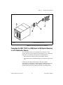


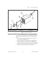


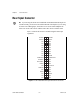
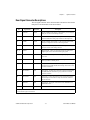
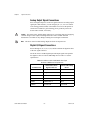
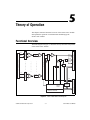


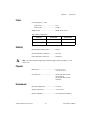


![[Unlocked] SC-2042](http://vs1.manualzilla.com/store/data/005660029_1-1367986a5e7a7fe673239a9957384234-150x150.png)