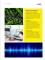
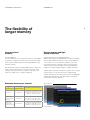
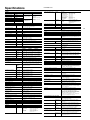
1
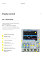
Precise
control and
flexibility
DLM2000 Series
Mixed Signal Oscilloscopes
Bulletin DLM2000-E-E
tmi.yokogawa.com
The DLM2000 embodies everything a user
would expect in an oscilloscope. It’s a
family of products that goes beyond the
demands and needs of users. Typical of a
company focused on quality, the DLM2000
has been built to last decades, crafted by
engineers to meet current demands and
future proofed to keep track with the ever
rapid changes in technology. A product
designed for the future but at today’s
prices.
The DLM2000 is a series of bench-top
oscilloscopes made for electronic design
and debug. It’s ergonomic, easy to
use, and complete with all the features
and more you would expect in today’s
oscilloscope. With bandwidths from 200
to 500 MHz and memory from 1 to 250
MPoints, there is a DLM2000 to meet your
application and budget.
Why choose the DLM2000?
Quality – As a bench-top instrument, an
oscilloscope is the most used piece of test
and measurement equipment. To meet the
rigors of everyday use it needs to be reliable.
Yokogawa’s reputation for high quality
products ensures the user is never let down
and can depend on the DLM2000
Innovation – The ever increasing demands
of today’s test needs means oscilloscopes
must be versatile and adapt to all sorts of
different applications. Yokogawa’s DLM2000
series is equipped with all the features
and more that an engineer requires in an
oscilloscope.
Foresight – Users experience a short
learning curve thanks to an intuitive
man-machine interface that is easy to use.
Keeping in touch with users has ensured
that any Yokogawa product introduced
to the market has been developed with their
needs in mind.
Why choose Yokogawa
Why choose Yokogawa
Our passion for measurement
Yokogawa believes that precise and effective
measurement lies at the heart of successful
innovation – and has focused its own R&D
on providing the tools that researchers and
engineers need to address their challenges
both great and small.
Our heritage
Yokogawa has been developing
measurement solutions for almost 100
years, consistently finding new ways to
give R&D teams the tools they need to gain
the best insights from their measurement
strategies. Our oscilloscope design has
been led by customers looking for ease-ofuse and functionality.
Our commitment
Yokogawa takes pride in its reputation for
quality, both in the products we deliver
– often adding new features in response
to specific client requests – and the level of
service and advice we provide to our clients,
helping to devise measurement strategies
for even the most challenging environments.
Precise control
DLM2000 Series
Precise control
4
Easy to use portrait design
The large display of a DLM2000 is located above the controls; this
enables it to be nearer the eyes of the user and keeps the footprint
on the bench to a minimum.
The intuitive controls are laid out so that a user can see at a glance
what channels and features are switched-on and quickly make the
measurements that are needed.
Easy to configure 8.4 inch display
Users can automatically or manually split the display to separate
individual channel waveforms while maintaining their full resolution
and dynamic range. It is therefore easy to see the details of all signals
regardless of the number of channels in use.
8
1
2
3
4
5
6
7
8
9
10
Horizontal Position and Scale Knob
Dedicated Zoom Keys
Four-Direction Selector Button
Select key moves the cursor up/down/left/right
Jog Shuttle and Rotary Knob
9
10
Logic input connector
3
Trigger Control Keys and Level Knob
Vertical Position and Scale
7
1
6
2
4
Large screen in a compact body
Snapshot key to freeze traces on-screen
Graphical on-line help key
Built-in manual
5
Fast and flexible
5
Fast and flexible
Flexible MSO input
Choose to capture a mix of analog and more digital signals.
With a push of a button, channel 4 converts into 8 digital inputs and
the DLM2000 becomes a mixed signal oscilloscope. This makes it
possible to view 3 analog and 8 digital signals simultaneously and
view more control and logic signals. Digital channels can also be
used to analyze I2C, SPI and UART serial buses which keep the
analog channels available for other signals.
ScopeCORE fast data processing
The hardware optimized architecture and dedicated ScopeCORE IC
in the DLM2000 enable measurements and signal processing to be
carried out in real time. This means that turning on more channels
does not affect the waveform acquisition rate and measurements are
always performed at high speed.
3 channels analog + 8-bit logic
The fast ScopeCORE
internal processor
DLM2000 series Lineup
Model
Analog
Bandwidth
DLM2022
200 MHz
DLM2024
200 MHz
DLM2032
350 MHz
Maximum
sample rate
2.5GS/s with
Interleave on
No of channels
Maximum record length (in single
measurement mode and with interleave on)
2 analog
62.5 MPoints
4 analog or 3 analog plus 8 digital
250 MPoints with /M3 option
2 analog
62.5 MPoints
DLM2034
350 MHz
4 analog or 3 analog plus 8 digital
250 MPoints with /M3 option
DLM2052
500 MHz
2 analog
62.5 MPoints
DLM2054
500 MHz
4 analog or 3 analog plus 8 digital
250 MPoints with /M3 option
The flexibility of longer memory
DLM2000 Series
The flexibility of
longer memory
6
Long waveform
memory
History memory and high
speed acquisition
Up to 250 MPoints
The two advantages of a long waveform memory are the abilities
to capture for long periods of time and to maintain high sample
rates, and hence higher effective measuring bandwidths for all
time base settings.
Capture and replay up to 50,000 acquisitions
With the history memory, the DLM2000 can capture and replay
up to 50,000 individual acquisitions. These can be displayed
one at a time or as an accumulation. Using the search and
measurement functions, abnormal signals can therefore be
quickly isolated, analyzed and precisely categorized without
needing to carefully configure triggers to capture rare events.
With the maximum memory installed (/M3 option), in single shot
mode, a 10 kHz signal lasting for more than one hour can be
captured. The same memory can capture a 200 millisecond
signal at a sample rate of 1.25GS/s sample rate.
Maximum memory per channel
Type of
Two analog
measurement channel models
Four analog channel models
Continuous
6.25 MPoints
6.25 MPoints (standard memory)
12.5 MPoints (with /M2 option)
25 MPoints (/with M3 option)
Single-shot
using all analog
channels
25 MPoints
25 MPoints (standard memory)
62.5 MPoints (with /M2 option
125 MPoints (with /M3 option)
Single-shot
using half the
analog channels
62.5 MPoints
62.5 MPoints (standard memory)
125 MPoints (with /M2 option)
250 MPoints (with /M3 option)
Together with a maximum continuous acquisition rate of 20,000
waveforms per second, which increases to approximately
450,000 in N Single mode, the history memory in the DLM2000
enables abnormal signals to be captured without needing to
know what makes them different.
Waveform history
Abnormal signal
Reliable triggering
7
Reliable triggering
When just a specific event or abnormal
waveform needs to be captured, the flexible
and reliable triggering of the DLM2000 is
the solution. The user can combine analog
and digital inputs and select the trigger
conditions appropriate to the complexity and
uniqueness of the event.
Enhanced triggers
Trigger on arbitrary serial bus patterns
Via the Enhanced menu, the DLM2000 can be set to trigger,
for example, on an edge of any channel, an edge or state when
conditions on other channels are met or when the width of a
pulse is either more or less than a specified time. Dedicated
triggers are also available for serial bus options.
In order to support any type of serial bus and thus the ability to
trigger on any combination of ID and data etc., a user define
trigger is provided. On one input channel, a pattern of up to 128
bits can be set and other channels can also be used for clock,
chip select and latch signals.
Edge trigger
Edge
Enhanced triggers
Edge OR
Edge (qualified)
State
HHHH-LHLH-LLLL
(Arbitrary pattern)
Trigger
Combination triggers
Via the B trigger menu two serial bus triggers can be combined,
which means that the DLM2000, for example, will trigger when
signal conditions on either a CAN bus or a LIN bus are met.
Pulse width
State width
Serial(optional)
CAN/LIN/UART/I2C/SPI
(standard) user defined
TVNTSC/PAL/SDTC/
HDTV/user defined
B triggers
A Delay B
A to B (n)
Dual bus
(combination trigger
of 2 serial busses)
LIN
CAN
Input signal A CAN
Input signal B LIN
The “A to B(n)” trigger provides the ability to trigger when a
specific number of edges has occurred on input B. This enables
measurements on signals with shifted timing, such as nonstandard video signals, and motor reference position pulses and
drive pulses to be easily made.
Input signal A
Input signal B
Triggering on the 7th edge of the B input signal
Trigger
Features and benefits
DLM2000 Series
Features and
benefits
Capable measurement and analysis
The DLM2000 is packed with advanced
capture and analysis features to provide
quick and comprehensive answers.
Real time filters and
post processed
digital filters
Two fully
independent zoom
windows
Advanced waveform
search functions
Automatic parameter
measurement and
statistical analysis
The DLM2000 has two types
of filter. Real time input filters,
with cut-offs from 8 kHz to
200 MHz, are selectable for
each channel and the filtered
data is stored in the internal
memory. Input waveforms
can also be filtered using
a digital IIR filter using the
mathematics (MATH) function.
This method enables the input
and filtered waveforms to be
simultaneously displayed and
compared. High and low pass
filters from 0.01 Hz to 500
MHz are selectable with a high
level of precision.
Combined with the advanced
search and cursor/parameter
measurement capabilities, the
two zoom windows enable
users, for example, to see the
waveform detail of two parts
of the acquisition which can
be separated by a long time
period. It is thus possible
to quickly find, measure
and analyze the details of
the cause and effect of an
abnormality which could be
on the same or different input
channels. They also make it
possible to view and compare
the details and timings of
different serial buses which
are running at different
speeds.
Quickly find and mark
abnormal signals in long
and multiple waveform
acquisitions.
30 waveform parameters
from a total of 29 different
types can be displayed
simultaneously with a high
update rate. These include:
maximum, minimum,
peak-to-peak, pulse width,
period, frequency, rise and fall
times, and the delay between
channels.
The image shows the
snapshot function which
freezes traces on the screen
to compare old and new
acquisitions.
Single waveform acquisitions
of up to 250 MPoints can be
searched using various criteria
such as edges, state patterns,
pulse widths and serial bus
patterns (optional).
The history memory can be
searched to find matching
criteria in up to 50,000
acquisitions.
The statistics of repetitively
measured parameters can
also be displayed, such as the
mean, maximum, minimum
and standard deviation.
Additionally, the Go/NO-GO
function can be used to test
the results of parameter
measurements, trigger
conditions and other criteria
and automatically save or print
data, send an e-mail etc.
8
Features and benefits
9
Parameter trend and
histogram displays
Automatically
measure time and
voltage differences
FFT frequency
domain analysis
User define math
To observe the fluctuations
of measured parameters, it
is possible to display them
as trends. Period-to-period
changes can then be
easily seen. The variation
of parameters can also be
displayed as histograms thus
providing a visual method of
assessing them statistically.
Line or waveform marker
cursors can be placed on
different displayed waveforms
and the absolute values
of voltage and time, and
their differences, can be
simply displayed. A degree
cursor can also be used by
converting the time axis into a
position/degree axis.
2 FFT analyses can be
performed simultaneously.
The source data can be
either from input channels
or the results of mathematical
computations. As well as
standard Power Spectrum
calculations, a full suite of
FFT functions are available
using the /G2 user define
math option.
Up to 2 math channels are
available. The standard
DLM2000 provides arithmetic
and filtering functions on
computations of up to 125
MPoints. By installing the /G2
option, the oscilloscope offers
comprehensive user defined
mathematics. Equations
can be arbitrarily created
using a suite of operators
such as trigonometric and
logarithmic operators,
integration and differentiation,
pulse width operators,
phase measurement and
digital to analogue conversion
(in the image).
When used in combination
with cursor and automatic
waveform measurements
on the computed waveforms,
the DLM2000 is able to
provide meaningful results
according to the user’s
specific requirements.
Serial bus triggering and analysis
DLM2000 Series
Serial bus triggering
and analysis
10
Up to 4 buses simultaneously
Power supply analysis options
Dedicated trigger and analysis options are available for FlexRay,
CAN, CAN FD, LIN, SENT, UART, I2C and SPI serial buses.
The /G3 and /G4 options enable switching loss, joule integral
(i2t), SOA (safe operating area), harmonics based on EN610003-2, and other power parameters to be measured and analyzed.
From most buses a wide variety of trigger combinations can
be set, including ID and Data combinations, which can also
be combined with conventional edge triggers. A serial bus
auto-setup enables the MSO to be quickly configured. The user
therefore does not need detailed knowledge of the bus frame
format.
Analysis can be performed at high speed simultaneously on
up to four different buses operating at different speeds. This is
enhanced by the extensive search facilities, allowing the user to
look for specific data in the very long memory. The dual-zoom
facility means that different buses can be viewed and debugged
alongside each other.
Simultaneous analyses of I2C
and SPI
Four bus decode and list display
Switching loss analysis
Using the long memory, the switching loss of the voltage and
current input waveforms can be computed (V(t) X i(t)) over
long time periods. The turn-on/off loss, the loss including the
continuity loss, and the loss over many cycles of the 50 Hz/60
Hz power line can be calculated and analyzed.
Power measurement
The MSO can also be used as a power meter by providing
automated measurement of power parameters for up to two
pairs of voltage and current waveforms, such as the active
power, apparent power and power factor. These values can then
be statistically processed and calculated.
Switching loss analysis
Power parameter measurement
Connectivity
11
Connectivity
2
1
2
3
4
5
6
7
8
9
Ehernet (optional)
Supports 1000BASE-T, 100BASE-TX, 10BASE-T.
Go/No-Go output terminal
TTL level output of the result of the GO/No-GO function.
RGB video signal output terminal
Check the image of the waveform on a external monitor.
USB-PC connection terminal
Enables control from a PC.
USB perpheral connection terminal
Supports USB storage, USB keyboards, USB printers.
Probe power terminal (optional)
Power supply for current and differential probes.
GP-IB connection terminal (optional)
Enables control from a PC.
External trigger input
An input for a trigger signal separate from the channel signals.
Trigger output
Output a CMOS 3.3V level trigger signal
1
6
3
4
7
5
8
9
1000BASE-T/100BASE-TX/10BASE-T
Hub or router
*
Hub or router
*
Sends waveform, screen, and settings data
Remote control
Mail transmission (GO/NO-GO action)
USB (standard on rear panel)
Ethernet
(/C10, /C11 options)
DLM2000
Supports USB:
*DLM2000’s internal storage can be recognized by a PC as an external USB storage device. Transferring files is easy even when a USB thumb drive can’t be used.
Sends waveform, screen,
and settings data
Remote control
Comprehensive software tools
DLM2000 Series
Comprehensive
software tools
A comprehensive suite of software tools
to support and complement complex
measurement tasks.
Free
XviewerLITE
Off-line
waveform
display and
analysis
Waveform
monitoring
on a PC
Data transfer
to a PC
Basic display and measurement
Provides zooming, vertical cursors and data conversion
to CSV format.
Xwirepuller
The DLM2000 can be simply controlled using a PC
and mouse via an Ethernet, USB, or GP-IB interface.
When the software program starts, a simulation of
the oscilloscope appears on the PC display.
Custom
software
development
Xviewer
Advanced analysis
Xviewer can display acquired waveforms,
transfer files and control instruments
remotely. In addition to simply displaying
the waveform data, Xviewer features many
of the same functions that the DLM2000
offers; zoom display, cursor measurements,
calculation of waveform parameters,
complex waveform math and FFT. Binary
waveform data can easily be converted to
CSV, Excel or Floating Point Decimal format.
LabVIEW drivers
MATLAB toolkit
By using the LabVIEW driver written for the
DLM2000, a developer can dramatically reduce the
amount of work required to enable a PC to control
the instrument from within the LabVIEW environment.
The MATLAB® tool kit can be used to control
the DLM2000 and to transfer data via GP-IB,
USB or Ethernet from within MATLAB.
TMCTL library
Command
control
Trial version available
This DLL (Dynamic Link Library) enables Microsoft
Visual studio programs, such as Visual C++
and Visual Basic, to be quickly developed to
communicate between the PC and the DLM2000. It
supports GPIB, USB and Ethernet interfaces.
DLTerm
The command line tool can be used with the
TMCTL library to develop communication programs.
Prototype code can be rapidly created to automate
sequences of capture, measurement and analysis
tasks before writing a fully custom software routine.
Symbol editor
Physical value symbol definition files for CAN serial
bus analysis can be created and edited. CANdb files
can also be imported.
12
Recommended Probes and accessories
13
Recommended
Probes and
accessories
The extensive range of Yokogawa probes
includes models which are designed and
optimized for specific applications.
For power electronics testing
For serial bus testing
PBC050 / PBC100 - Current probes*
DC to 50 MHz / 100 MHz
30 Arms
PBDH1000 – 1GHz differential probe
1 M ohm / 1.1pF input
±25 V differential voltage input
Compatible with the FlexRay standard
PBDH0150 - differential probe
DC to 150 MHz
1400 V (DC +ACpeak) differential
and common mode voltage
701920 / 701922
differential probes
500 MHz / 200 MHz
±12 V / ±20V
differential voltage input
Logic probes
PBL100 / PBL250 8 bit logic probes
100 MHz / 250 MHz toggle frequency
1 M ohm / 100 K ohm input
701926 – differential probe*
DC to 50 MHz
5000 Vrms / 7000 Vpeak
PBA1000 1 GHz Active probe
100 k ohm / 0.9 pF input
701936 deskew correction signal source
*Higher current and other differential probes are available. See page 16
Specifications
Models
DLM2000 Series
Trigger type, trigger source
Model name
Frequency
bandwidth
DLM2022 (710105)
200MHz
DLM2032 (710115)
350MHz
DLM2052 (710125)
500MHz
DLM2024 (710110)
200MHz
DLM2034 (710120)
350MHz
DLM2054 (710130)
500MHz
Input terminal
Max. sample rate
2 analog channels
1.25GS/s
(interleave mode off)
4 analog channels /
3 analog channels
+ 8bit logic
2.5GS/s
(interleave mode on)
A triggers
AB triggers
Basic Specifications
Analog Signal input
Input channels
Analog input
Input coupling setting
DLM20x2: CH1, CH2
DLM20x4: CH1 to CH4
(CH1 to CH3 when using logic input)
1 MΩ 1.0%, approximately 20 pF
50 Ω 1.0% (VSWR 1.4 or less, DC to 500MHz)
Voltage axis sensitivity
1MΩ
2 mV/div to 10 V/div (steps of 1-2-5)
setting range
50 Ω
2 mV/div to 500 mV/div (steps of 1-2-5)
Max. input voltage
1 MΩ
150 Vrms
50 Ω
Must not exceed 5 Vrms or 10 Vpeak
1 MΩ
±1V (2 mV/div to 50 mV/div)
±10V (100 mV/div to 500 mV/div)
±100V (1 V/div to 10 V/div)
50 Ω
±1V (2 mV/div to 50 mV/div)
±5V (100 mV/div to 500 mV/div)
Max. DC offset
setting range
Trigger level setting range
CH1 to CH4
±4 div from center of screen
CH1 to CH4
0.01 div (TV trigger: 0.1 div)
CH1 to CH4
±(0.2 div + 10% of trigger level)
Trigger level accuracy
Analog input
Window Comparator
Offset voltage accuracy*1
2 mV to 50mV/
div
±(1% of setting +0.2 mV)
100 mV to 500
mV/div
±(1% of setting + 2 mV)
1 V to 10 V/div
±(1% of setting + 20 mV)
Display
1 MΩ (when using passive
probe)
50 Ω
DLM203x
8.4-inch TFT color liquid crystal display 1024 x 768 (XGA)
Functions
Waveform acquisition modes
Normal, Envelope, Average
High Resolution mode
Max. 12 bit (the resolution of the A/D converter can be
improved equivalently by placing a bandwidth limit on the
input signal.)
Sampling modes
Real time, interpolation, repetitive sampling
Accumulation
Select OFF, Intensity (waveform frequency by
brightness), or Color (waveform frequency by color)
Accumulation
time
Roll mode
DLM205x
100 mV to 100
V/div
DC to 200 MHz DC to 350 MHz DC to 500 MHz
20 mV to
50 mV/div
DC to 150 MHz DC to 300 MHz DC to 400 MHz
10 mV to
500mV/div
DC to 200 MHz DC to 350 MHz
DC to 500 MHz
2 mV to
5 mV/div
DC to 150 MHz DC to 300 MHz
DC to 400 MHz
History memory
100 ms to 100 s, Infinite
Enabled at 100 ms/div to 500 s/div (depending on the
record length setting)
Zoom function
Frequency characteristics (-3 dB attenuation when inputting a sinewave of amplitude ± 3div)*1*2
DLM202x
Center/Width can be set on individual Channels from
CH1 to CH4
Display
±(1.5% of 8 div + offset voltage accuracy)
DC accuracy*1
CH1 to CH4, Logic
CH1 to CH4, Logic
CH1 to CH4, Logic
CH1 to CH4
CH1 to CH4
CH1 to CH4
CH1 to CH4
CH1 to CH4, Logic
CH1 to CH4
10 ns to 10 s (Edge, Edge
Qualified, State, Serial Bus)
1 to 109 (Edge, Edge
Qualified, State, Serial Bus) Dual
Serial bus only
Trigger level setting
resolution
*1
AC, DC, DC50 Ω, GND
Input impedance
Serial Bus
I2C (optional)
SPI (optional)
UART (optional)
FlexRay (optional)
CAN (optional)
CAN FD (optional)
LIN (optional)
SENT (optional)
User defined
A Delay B
A to B(N)
Bus
Two zooming windows can be set independently
(Zoom1, Zoom2)
Zoom factor
x2 to 2.5 points/10div (in zoom area)
Scroll
Auto Scroll
Search
functions
Edge, Edge Qualified, State, Pulse Width, State Width
I2C (option), SPI (option), UART (option), CAN (option),
LIN (option), Flexray (option)
Max. data
10,000 (record length 1.25 kPoints, with /M1 or /M1S
option)
20,000 (record length 1.25 kPoints, with /M2 option)
50,000 (record length 1.25 kPoints, with /M3 option)
History search
Select Rect, WAVE, Polygon, or Parameter mode
Isolation between channels
-34 dB@ analog bandwidth (typical value)
Replay
function
Automatically displays the history waveforms
sequentially
Residual noise level*3
The larger of 0.4 mV rms or 0.05 div rms (typical value)
Display
Specified or average waveforms
A/D resolution
8bit (25LSB/div) Max. 12 bit (in High Resolution mode)
Cursor
Types
Bandwidth limit
FULL, 200 MHz, 100MHz, 20 MHz, 10 MHz, 5 MHz, 2
MHz, 1 MHz, 500 kHz, 250 kHz, 125 kHz, 62.5 kHz, 32
kHz, 16 kHz, 8 kHz (can be set for each channel)
ΔT, ΔV, ΔT & ΔV, Marker, Degree
Snapshot
Real time
sampling
mode
Interleave OFF 1.25 GS/s
Interleave ON 2.5 GS/s
Parameter measurement
Repetitive
sampling
mode
125 GS/s
Max, Min, P-P, High, Low, Rms, Mean, Sdev, IntegTY+,
IntegTY, +OVER, -OVER, Pulse Count, Edge Count, V1,
V2, ΔT, Freq, Period, Avg Freq, Avg Period, Burst, Rise,
Fall, +Width, -Width, Duty, Delay
Statistical computation of parameters
Min, Max, Mean, standard deviation, Count
2 ch model
(/M1S)
Repeat/Single/Single Interleave:
6.25 M/25 M/62.5 MPoints
Statistics modes
Continuous, Cycle, History
Trend/Histogram display of wave parameters
4 ch model
(/M1S)
Repeat/Single/Single Interleave:
6.25 M/25 M/62.5 MPoints
Up to 2 trend or histgram display of specied wave
parameters
Computations (MATH)
4 ch model
(/M2)
Repeat/Single/Single Interleave:
12.5 M/62.5 M/125 MPoints
+, -, x, Filter (Delay, Moving Avg, IIR Lowpass, IIR
Highpass), Integ, Count (Edge, Rotary), user defined
math (optional)
4 ch model
(/M3)
Repeat/Single/Single Interleave:
25 M/125 M/250 MPoints
Computable no. of traces
2 (Math1, Math2) (1 trace for 2ch model)
Max. computable memory length
/M1, /M1S option: 25 MPoints
/M2 option: 62.5 MPoints
/M3 option: 125 MPoints
Reference function
Up to 2 traces (REF1/REF2) of saved waveform data
can be displayed and analyzed
Modes: Rect, Wave, Polygon, Parameter
Actions: Buzzer, Print, Save, Mail
Maximum sample rate
Maximum record length
Currently displayed waveform can be retained on screen
Computation & Analysis Functions
Ch-to-Ch deskew
±100 ns
Time axis setting range
1 ns/div to 500 s/div (steps of 1-2-5)
Time base accuracy*1
± 0.002%
Max. acquisition rate*4
Approx. 20,000 waveform/sec/ch (Accumulation mode)
Action ON trigger
GO/NO-GO
Dead time in N Single mode
Approx. 2.2μs (approx. 450,000 waveforms/sec/ch)
XY
Displays XY1, to XY2 and T-Y simultaneously
FFT
Number of points: 1.25k, 12.5k, 25k, 125k, 250k
Window functions: Rectangular, Hanning, Flat-Top
FFT Types: PS (LS, RS, PSD, CS, TF, CH are available
with /G2 or /G4 option)
Histogram
Displays a histogram of acquired waveforms
User-defined math (/G2 option)
The following operators can be arbitrarily combined in
equations:
+, -, x, /, SIN, COS, TAN, ASIN, ACOS, ATAN, INTEG, DIFF, ABS, SQRT, LOG, EXP, LN, BIN, DELAY,
P2 (power of 2), PH, DA, MEAN, HLBT, PWHH, PWLL,
PWHL, PWLH, PWXX, FV, DUTYH, DUTYL,
The maximum record length that can be computed is
the same as the standard math functions
Logic Signal Input (4 ch model only)
Number of inputs
8 bit (excl. 4 ch input and logic input)
Maximum toggle frequency
Logic probe 701988: 100 MHz
Logic probe 701989: 250 MHz
Compatible probes
701988, 701989 (8 bit input)
(701980, 701981 are available)
Min. input voltage
701988: 500 mVp-p
701989: 300 mVp-p
Input range
Model 701988: ±40 V
Model 701989: threshold ±6V
Max. nondestructive input voltage
±40 V (DC + ACpeak) or 28 Vrms (when using 701989)
Threshold level setting range
Model 701988: ±40 V (setting resolution of 0.05 V)
Model 701989: ±6 V (setting resolution of 0.05 V)
Input impedance
701988: Approx. 1 MΩ/approx. 10 pF
701989: Approx. 100 kΩ/approx. 3 pF
*1
Maximum sampling rate
Maximum record length
Power supply analysis (/G3, /G4 option)
Power analysis
Switching loss
Total loss / switching loss, power waveform display,
Automatic measurement and statistical analysis of
power analysis items (Wp, Wp+, Wp-, Abs.Wp, P, P+,
P-, Abs.P, Z)
Repeat: 25 MPoints, Single: 125 MPoints
Safety
operation area
SOA analysis by X-Y display, using voltage as X axis,
and current as Y axis is possible
Auto, Auto Level, Normal, Single, N-Single
Harmonic
analysis
Basic comparison is possible with following standard
Harmonic emission standard IEC61000-3-2 edition
2.2, EN61000-3-2(2000), IEC61000-4-7 edition 2
Joule integral
Joule integral (I2t) waveform display, automatic
measurement and statistical analysis is possible
1.25 GS/s
/M1, /M1S option
Repeat: 6.25 MPoints, Single: 25 MPoints
/M2 option
Repeat: 12.5 MPoints, Single: 62.5 MPoints
/M3 option
Triggers
Trigger modes
Trigger type, trigger source
A triggers
For Pwr1 and Pwr2, selectable from 4 analysis types
De-skewing between the voltage and current waveforms
can be executed automatically.
Edge
Edge OR
Edge Qualified
State
Pulse width
State width
TV
CH1 to CH4, Logic, EXT, LINE
CH1 to CH4
CH1 to CH4, Logic, EXT
CH1 to CH4, Logic
CH1 to CH4, Logic, EXT
CH1 to CH4, Logic
CH1 to CH4
Power Measurement
Automated measurement of power parameters for up to
two pairs of voltage and current waveforms
Values can be statistically processed and calculated
Measurement
parameters
Urms, Unm, Udc, Urmn, Uac, U+pk, U-pk, Up-p
Irms, Imn, Idc, Irmn, Iac, I+pk, I-pk, Ip-p P, S, Q,
Z, λ, Wp, Wp+, Wp-, Abs.Wp, q, q+, q-, Abs.q
Avg Freq(voltage, current)
14
I2C Bus Signal Analysis Functions (/F2 & /F3 Options)
Applicable bus
Bus transfer rate: 3.4 Mbit/s max.
Address mode: 7 bit/10 bit
SM bus
Complies with System Management Bus
Analyzable signals
CH1 to CH4, Logic input, or M1 to M2
I C Trigger modes
Every Start, Address & Data, Non-Ack, General Call,
Start Byte, HS Mode
Analysis results displays
Analysis no., time from trigger position (Time (ms)),1st
byte address, 2nd byte address, R/W, Data, Presence/
absence of ACK, information
2
FlexRay Bus Signal Analysis Functions (/F5, /F6 and /F8 Options)
Applicable bus
FlexRay Protocol Version2.1
Analyzable signals
CH1 to CH4, M1 to M2
Bit rate
10 Mbps, 5 Mbps, 2.5Mbps
FlexRay bus Trigger modes
Frame Start, Error, ID/Data, ID OR
Auto setup function
Auto setting of bit rate, threshold value, time axis scale,
voltage axis scale, and display of analysis results
Analyzable no. of frames
5,000
Analysis results displays
Analysis no., time from trigger positions (Time(ms)),
Segment (Static or Dynamic), Indicator, FramID,
PayLoad length, Cycle count, Data, Information
Auto setup function
Auto setting of threshold value, time axis scale, voltage
axis scale, and display of analysis results
Analyzable no. of data
300,000 bytes max.
Auxiliary analysis functions
Data search
Search function
Searches data that matches specified address pattern,
data pattern, and acknowledge bit condition
Analysis result save function
Analysis list data can be saved to CSV-format files
Analysis list data can be saved to CSV-format files
Applicable standard
Analyzable signals
Clock period
Data type
Analysis results save function
SENT Signal Analysis Functions (/F9 Option)
SPI Bus Signal Analysis Functions (/F2 & /F3 Options)
Trigger types
3 wire/4 wire
After assertion of CS, compares data after arbitrary byte
count and triggers.
Analyzable signals
CH1 to CH4, Logic input, M1 to M2
Byte order
MSB/LSB
Auto setup function
Auto setting of threshold value, time axis scale, voltage
axis scale, and display of analysis results
Analyzable no. of data
300,000 bytes max.
Decode bit length
Specify data interval (1 to 32 bits), decode start point,
and data length
Analysis results displays
Analysis no., time from trigger position (Time (ms)), Data
1, Data 2
Auxiliary analysis functions
Data search function
Analysis result save function
Analysis list data can be saved to CSV-format files
SENT trigger modes
Auto setup function
Analyzable no. of frames
Analysis results displays
Auxiliary analysis functions
Analysis result save function
UART Bus Signal Analysis Functions (/F1 & /F3 Options)
Bit rate
Fast channel
Slow channel
J2716 JAN2010 and older
CH1 to CH4, logic input, or M1 to M2
1 us to 100 us with resolution of 0.01 us
Fast channel
Nibbles/User Defined
Slow channel Short/Enhanced
Start of fast channel
Auto setting of clock period, nibble number, pause pulse,
threshold value, time axis scale, voltage axis scale, and
display of analysis results
100,000 frames max.
Analysis no., time from trigger position (Time (ms)),
Sync/Cal period, Tick, Status & Comm, Data, CRC,
frame length, information
Analysis no., time from trigger position (Time (ms)), ID,
Data, CRC, information
Data search and trend functions
Analysis list data and trend data can be saved to CSVformat files
GP-IB (/C1 & /C11 Options)
1200 bps, 2400 bps, 4800 bps, 9600 bps,19200 bps,
user defined (an arbitrary bit rate from 1 k to 1 Mbps
with resolution of 100 bps)
Electromechanical specifications
Conforms to IEEE std. 488-1978 (JIS C 1901-1987)
Protocol
Conforms to IEEE std. 488.2-1987
Analyzable signals
CH1 to CH4, logic input, or M1 to M2
Data format
Select a data format from the following 8 bit (Non Parity)
/ 7 bit Data + Parity / 8 bit + Parity
UART Trigger modes
Every Data, Data, Error (Framing, Parity)
Auto setup function
Auto setting of bit rate, threshold value, time axis scale,
voltage axis scale, and display of analysis results
Analyzable no. of frames
300,000 frames max.
Internal Storage (Standard model /C9 Option)
Analysis results displays
Analysis no., time from trigger position (Time(ms)), Data
(Bin, Hex) display, ASCII display, and Information.
Capacity
Auxiliary analysis functions
Data search
Built-in printer
Analysis result save function
Analysis list data can be saved to CSV-format files
USB Peripheral Connection Terminal
Auxiliary Input
Rear panel I/O signal
External trigger input(DLM20x2: front panel), external
trigger output, GO-NOGO output, video output
Probe interface terminal (front panel)
4 terminals (DLM20x4) 2 terminals (DLM20x2)
Probe power terminal (rear panel)
2 terminals (/P2 option) 4 terminals (/P4 option)
Standard model: 300 MB /C9 option: 7.2 GB
Built-in Printer (/B5 Option)
CAN Bus Signal Analysis Functions (/F4, /F6, /F7 and /F8 Options)
112 mm wide, monochrome, thermal
Connector
Applicable bus
CAN version 2.0A/B, Hi-Speed CAN (ISO11898), LowSpeed CAN (ISO11519-2)
USB type A connector x 2
(front panel x 1, rear panel x 1)
Electromechanical specifications
USB 2.0 compliant
Analyzable signals
CH1 to CH4, M1 to M2
Supported transfer standards
Low Speed, Full Speed, High Speed
Bit rate
1 Mbps/500 kbps/250 kbps/125 kbps/83.3 kbps/ 33.3
kbps
User defined (an arbitrary bit rate from 10.0 kbps to
1.000 Mbps with resolution of 100 bps)
Supported devices
USB Printer Class Ver. 1.0 compliant EPSON/HP
(PCL) ink jet printers USB Mass Storage Class Ver. 1.1
compliant mass storage devices* Please contact your local
Yokogawa sales office for model names of verified devices
CAN bus Trigger modes
SOF, ID/DATA, ID OR, Error(enabled when loading
physical values/symbol definitions)
USB-PC Connection Terminal
Auto setup function
Auto setting of bit rate, threshold value, time axis scale,
voltage axis scale, and display of analysis results
Connector
USB type B connector x 1
Electromechanical specifications
USB 2.0 compliant
Analyzable no. of frames
100,000 frames max.
Supported transfer standards
High Speed, Full Speed
Analysis results displays
Analysis no., time from trigger position (Time (ms)),
Frame type, ID, DLC, Data, CRC, presence/absence of
Ack, information
Supported class
USBTMC-USB488 (USB Test and Measurement Class
Ver. 1.0)
Auxiliary analysis functions
Data search and field jump functions
Analysis result save function
Analysis list data can be saved to CSV-format files
Ethernet (/C10 & /C11 Options)
CAN FD Bus Signal Analysis Functions (/F7 and /F8 Options)
Applicable bus
Analyzable signals
Bit rate
CAN FD Version 1.0
CH1 to CH4, M1 to M2
Arbitration
1 Mbps, 500 kbps, 250 kbps, User Define (an arbitrary bit
rate from 20 kbps to 1 Mbps with resolution of 100 bps)
Data
8 Mbps, 5 Mbps, 4 Mbps, 2 Mbps, 1 Mbps, 500 kbps,
User Define (an arbitrary bit rate from 250kbps to10Mbps
with resolution of 100 bps)
CAN FD bus trigger modes
SOF, ID, ID OR, Error Frame, Message (enabled when
loading physical values/symbol definitions)
Auto setup function
Auto setting of bit rate, recessive Level, threshold value,
time axis scale, voltage axis scale, and display of analysis
results
Analyzable no. of frames
50,000 frames max.
Analysis results displays
Analysis no., time from trigger position (Time (ms)), Frame
type, ID, DLC, Data, CRC, presence/absence of Ack,
information
Auxiliary analysis functions
Data search and field jump functions
Analysis result save function
Analysis list data can be saved to CSV-format files
LIN Bus Signal Analysis Functions (/F4, /F6, /F7 and /F8 Options)
Applicable bus
LIN Rev. 1.3, 2.0, 2.1
Analyzable signals
CH1 to CH4, M1 to M2
Bit rate
19.2 kbps, 9.6 kbps, 4.8 kbps, 2.4 kbps, 1.2 kbps
User defined (an arbitrary bit rate from 1000 bps to 200
kbps with resolution of 10 bps)
LIN bus Trigger modes
Break Synch, ID/DATA, ID OR, and ERROR trigger
Auto setup function
Auto setting of bit rate, treshold value, time axis scale,
voltage axis scale, and display of analysis results
Analyzable no. of frames
100,000 frames max.
Analysis results displays
Analysis no., time from trigger position (Time (ms)), ID,
ID-Field, Data, CheckSum, information
Auxiliary analysis functions
Data search and field jump functions
Analysis result save function
Analysis list data can be saved to CSV-format files
Connector
RJ-45 connector x 1
Transmission methods
Ethernet (1000BASE-T/100BASE-TX/10BASE-T)
Supported services
Server: FTP. HTTP, VXI-11
Client: FTP, SMTP, SNTP, LPR, DHCP, DNS
General Specifications
Rated supply voltage
100 to 240 VAC
Rated supply frequency
50 Hz/60 Hz
Maximum power consumption
170 VA
External dimensions
226 (W) x 293 (H) x 193 (D) mm (when printer cover is
closed, excluding protrusions)
Weight
Approx.4.2kg With no options
Operating temperature range
5 ˚C to 40 ˚C
Measured under standard operating conditions after a 30-minute warm-up followed by calibration.
Standard operating conditions: Ambient temperature: 23˚C ±5˚C. Ambient humidity: 55 ±10% RH. Error
in supply voltage and frequency: Within 1% of rating.
*2
Value in the case of repetitive phenomenon. The frequency bandwidth of a single-shot phenomenon is
the smaller of the two values, DC to sampling frequency/2.5 or the frequency bandwidth of the repetitive
phenomenon.
*3
When the input section is shorted, the acquisition mode is set to Normal, accumulation is OFF, and the
probe attenuation is set to 1:1.
*4
Acquisition rate does not vary with an increase or decrease in channels.
*1
External Dimensions
Unit: mm
293
15
I2C bus
193
226
Model and
Suffix Codes
Section
title
Standard Main Unit Accessories
Title
Description
Part Name
Quantity
710105
DLM2022 Digital Oscilloscope, 2ch, 200MHz
Power cord
1
Passive probe, model 701938 (200 MHz,
1.5 m) For models 710105, 710110*1
Per number of channels
Model code
Suffix code
710110*1
DLM2024 Mixed Signal Oscilloscope, 4ch, 200MHz
710115
DLM2032 Digital Oscilloscope, 2ch, 350MHz
710120*1
DLM2034 Mixed Signal Oscilloscope, 4ch, 350MHz
DLM2052 Digital Oscilloscope, 2ch, 500MHz
Passive probe, model 701939 (500 MHz,
1.3 m) For models 710115, 710120,
710125, 710130*2
Per number of channels
710125
710130*1
Power cord
DLM2054 Mixed Signal Oscilloscope, 4ch, 500MHz
Protective front cover
1
-D
UL/CSA standard
Soft carrying case for probes
1
-F
VDE standard
Printer roll paper (for /B5 option)
1 roll
-Q
BS standard
User’s manuals*3
1 set
-R
AS standard
-H
GB standard
-N
Language
Option
The 701938 probes are not included when /EX22 or /EX24 is selected.
The 701939 probes are not included when /EX52 or /EX54 is selected.
*3
Operation guide as the printed material, and User’s manual as CD-ROM are included.
*1
*2
NBR standard
-HE
English Menu and Panel
Additional Option License for DLM2000*1
-HC
Chinese Menu and Panel
Model
Suffix code
Description
-HK
Korean Menu and Panel
709810
-G2
User defined math (4 ch model only)
-HG
German Menu and Panel
-G3
Power supply analysis function (4 ch model only)
-HF
French Menu and Panel
-G4
Power supply analysis function (includes /G2) (4 ch model only)
-HL
Italian Menu and Panel
-F1
UART trigger and analysis (4 ch model only)
-HS
Spanish Menu and Panel
-F2
I2C + SPI trigger and analysis (4 ch model only)
No switchable logic input (4 ch model only)
-F3
UART + I2C + SPI trigger and analysis (4 ch model only)
-F4
CAN + LIN trigger and analysis (4 ch model only)
-F5
FlexRay trigger and analysis (4 ch model only)
-F6
CAN + LIN + FlexRay trigger and analysis (4 ch model only)
-F7
CAN+CAN FD+LIN trigger and analysis (4 ch model only)
-F8
FlexRay+CAN+CAN FD+LIN trigger and analysis (4 ch model only)
-F9
SENT analysis (4 ch model only)
-X1
F4 -> F7 or F6 -> F8 (add CAN FD)
/P2*3
Built-in printer
Memory expansion option (4 ch model only) During
continuous measurement: 6.25 Mpoints; Single mode: 25
Mpoints (when interleave mode ON: 62.5 Mpoints)
Memory expansion option (4 ch model only) During
continuous measurement: 12.5 Mpoints; Single mode: 62.5
Mpoints (when interleave mode ON: 125 Mpoints)
Memory expansion option (4 ch model only) During
continuous measurement: 25 Mpoints; Single mode: 125
Mpoints (when interleave mode ON: 250 Mpoints)
Memory expansion option (2 ch model only) During
continuous measurement: 6.25 Mpoints; Single mode:25
Mpoints (when interleave mode ON: 62.5 Mpoints)
Probe power for 2 ch models
/P4*3
Probe power for 4 ch models
Name
Model
Specification
/C1*4
GP-IB Interface
Logic probe (PBL100)
701988
1 MΩ input resistance, toggle frequency of 100 MHz
/C10*4
Ethernet Interface
Logic probe (PBL250)
701989
100 kΩ input resistance, toggle frequency of 250 MHz
/C11*4
GP-IB + Ethernet Interface
Passive probe*1
701938
10 MΩ (10:1), 200 MHz, 1.5 m
/C9
/LN
/B5
/M1*2
(Standard)
/M2
*2
/M3*2
/M1S
(Standard)
16
Separately sold license product (customer-installable).
*1
Accessory Models
Internal storage (7.2 GB)
Passive probe*1
701939
10 MΩ (10:1), 500 MHz, 1.3 m
/G2*5
User defined math (4 ch model only)
Miniature passive probe
701946
10 MΩ (10:1), 500 MHz, 1.3 m
/G3*5
FET probe
700939
DC to 900 MHz bandwidth/2.5MΩ/1.8pF
Active probe (PBA1000)
701912
DC to 1 GHz bandwidth/100kΩ/0.9pF
/F1
Power supply analysis function (4 ch model only)
Power supply analysis function (includes /G2)
(4 ch model only)
UART trigger and analysis (4 ch model only)
100:1 voltage probe
701944
DC to 400 MHz, 1.2 m, 1000 Vrms
/F2*6
I2C + SPI trigger and analysis (4 ch model only)
100:1 voltage probe
701945
DC to 250 MHz, 3 m, 1000 Vrms
/F3*6
UART + I2C + SPI trigger and analysis (4 ch model only)
Differential probe
701921
DC to 100 MHz bandwidth/max. ±700 V
Differential probe
701922
DC to 200 MHz bandwidth/max. ±20 V
/G4*5
*6
/F4*7
CAN + LIN trigger and analysis (4 ch model only)
/F5*7
FlexRay trigger and analysis (4 ch model only)
Differential probe (PBDH1000)
701924
DC to 1 GHz bandwidth/1MΩ/max. ±25 V
/F6*7
FlexRay+CAN+LIN trigger and analysis (4 ch model only)
Differential probe
701926
DC to 50 MHz bandwidth, 5000 Vrms/7000 Vpeak
/F7* 7
CAN+CAN FD+LIN trigger and analysis (4 ch model only)
FlexRay+CAN+CAN FD+LIN trigger and analysis
(4 ch model only)
SENT analysis (4 ch model only)
Differential probe (PBDH0150)
701927
DC to 150 MHz bandwidth, max, ±1400V
Differential probe
700924
DC to 100 MHz bandwidth/max. ±1400 V
Differential probe
700925
DC to 15 MHz bandwidth/max. ±500 V
Differential probe
701920
DC to 500 MHz bandwidth/max. ±12 V
Current probe (PBC050)*2
701929
DC to 50 MHz bandwidth, 30 Arms
Current probe (PBC100)*2
701928
DC to 100 MHz bandwidth, 30 Arms
Current probe*2
701930
DC to 10 MHz bandwidth, 150 Arms
Current probe*2
701931
DC to 2 MHz bandwidth, 500 Arms
Deskew correction signal source
701936
For deskew correction
Printer roll paper
B9988AE
Lot size is 10 rolls, 10 meters each
Probe stand
701919
Round base, 1 arm
Carrying case
701964
Also for DL1600/DL1700E Series
/F8*7
/F9
/EX22*8 Attach two 701946 probes (For 2ch, 200 MHz models)
/EX24*8 Attach four 701946 probes (For 4ch, 200 MHz models)
/EX52*9 Attach two 701946 probes (For 2ch, 350/500 MHz models)
/EX54*9 Attach four 701946 probes (For 4ch, 350/500 MHz models)
*1
Logic probes sold separately. Please order the model 701988/701989 accessory logic probes separately.
*2
Only one of thes may be selected at a time.
*3
Specify this option when using current probes or other differential probes that don’t support probe interface.
*4
Only one of these may be selected at a time.
*5
Only one of these may be selected at a time.
*6
Only one of these may be selected at a time.
*7
Only one of these may be selected at a time.
*8
The 701938 probes are not included when this option is selected.
*9
The 701939 probes are not included when this option is selected.
[DLM is a pending trademark or registered trademark of Yokogawa Electric Corporation.] Any company’s
names and product names appearing in this document are the registered trademarks or trademarks of their
respective companies.
For the accessories for 701938, 701939 probe, various adapters are available. Please refer to DL series Accessories
brochure.
*2
Current probes’ maximum input current may be limited by the number of probes used at a time.
*1
Accessory Software
Name
Model
Specification
MATLAB tool kit
701991
MATLAB plug-in
Xviewer
701992-SP01
For DL/DLM Series, standard version
701992-GP01
For DL/DLM Series, with MATH functions
NOTE Before operating the product, read the user’s manual thoroughly for proper and safe operation.
YOKOGAWA EUROPE B.V.
Phone: (31)-88-4641000
Euroweg 2, 3825 HD Amersfoort, The Netherlands
E-mail: [email protected], tmi.yokogawa.com
YOKOGAWA METERS & INSTRUMENTS CORPORATION
Global Sales Department Phone: +81-42-534-1413
E-mail: [email protected]
YOKOGAWA CORPORATION OF AMERICA
Phone: (1)-770-253-7000
YOKOGAWA ENGINEERING ASIA PTE. LTD.
Phone: (65)-62419933
Fax: (31)-88-4641111
Subject to change
without notice.
Fax: +81-42-534-1426
Bulletin DLM2000-E-E
Edition 2
Fax: (1)-770-254-0928
Fax: (65)-62412606
Copyright Yokogawa 2014.
Printed in The Netherlands 2015.