1
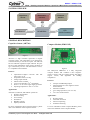
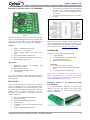
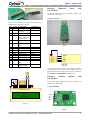
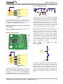
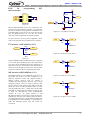
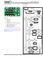
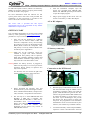
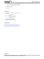
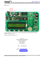
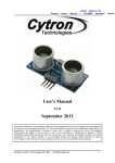
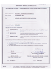
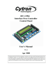
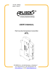
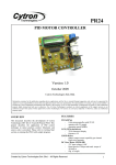
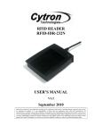
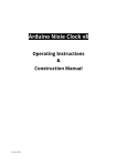
PR22
Reading Compass Module, Capacitive
And Barometric Pressure Sensors PR22
Version 1.0
August 2008
Cytron Technologies Sdn. Bhd.
Information contained in this publication regarding device applications and the like is intended through suggestion only and may be superseded by
updates. It is your responsibility to ensure that your application meets with your specifications. No representation or warranty is given and no liability is
assumed by Cytron Technologies Incorporated with respect to the accuracy or use of such information or infringement of patents or other intellectual
property rights arising from such use or otherwise. Use of Cytron Technologies’s products as critical components in life support systems is not
authorized except with express written approval by Cytron Technologies. No licenses are conveyed, implicitly or otherwise, under any intellectual
property rights.
OVERVIEW
FEATURES
This document describes the development of Cytron
Technologies DIY (Do It Yourself) Project No.22
(PR22). This project will use PIC16F876A, capacitive
sensor, compass module, barometric pressure sensor
and LCD. The function of the circuit is to read
capacitive sensor, compass module and barometric
pressure sensor, and display the readings on LCD.
Circuit schematic and PIC source code will be
provided.
PIC16F876A
- 8-bit microcontroller with 22 I/O
- Operates with 5V supply
LCD (2X16 characters)
- 2X16 characters display
- Operate at 5V supply
Compass Module (Optional)
- Works in strong magnetic field environments
- Operates at 3.3V supply
Capacitive Sensor (Optional)
- Includes temperature sensor
- Operates at 3.3V supply
Barometric Pressure Sensor (Optional)
- Includes temperature sensor
- Operates at 3.3V supply
Created by Cytron Technologies Sdn. Bhd. – All Rights Reserved
1
ROBOT . HEAD to TOE
PR22 – Reading Compass Module, Capacitive & Barometric Pressure Sensors
SYSTEM OVERVIEW
Capacitive Sensor Barometric Pressure
I2C
Push Buttons Compass Module I2C
SPI
LCD (2X16 Character)
PIC16F876A GENERAL DESCRIPTION
Capacitive Sensor (AD7746)
Compass Module (HMC6352)
Figure 1
AD7746 is a high resolution capacitance to digital
converter (CDC). The capacitance to be measured is
connected directly to the device inputs. The AD7746
has two channels capacitance input channels. The part
has an on-chip temperature sensor with a resolution of
0.1ºC and accuracy of ±2ºC. The AD7746 has a 2-wire,
I2C-compatible serial interface.
Features:
•
•
•
•
•
•
•
Capacitance-to-digital converter with full
scale range: ±4 pF
Temperature sensor on-chip
Voltage input channel
Internal clock oscillator
2-wire serial interface (I2C®-compatible)
Power: 2.7V to 5.25V single-supply operation
Operating temperature: -40ºC to +125ºC
Applications:
Automotive, industrial, and medical systems for
• Pressure measurement
• Position sensing
• Level sensing
• Flowmeters
• Humidity sensing
• Impurity detection
For more information about Capacitive Sensor, please
refer to the datasheet of the Capacitive Sensor.
Figure 2
The Honeywell HMC6352 is a fully integrated
compass module that combines 2-axis magnetoresistive sensors with the required analog and digital
support circuits, and algorithms for heading
computation.
Features:
•
•
•
•
•
Compass with Heading Output
Full integration of 2-axis magnetic sensors
and electronics
Firmware included
Low voltage operation (2.7V to 5.2V)
I2C 2-wire serial interface
Applications:
•
•
•
•
Wireless phones
Consumer electronics
Vehicle compassing
Antenna Positioning
For more information about Compass Module, please
refer to the datasheet of the Compass Module.
Created by Cytron Technologies Sdn. Bhd. – All Rights Reserved
2
ROBOT . HEAD to TOE
PR22 – Reading Compass Module, Capacitive & Barometric Pressure Sensors
Barometric Pressure Sensor (SCP1000-D01)
•
•
The synchronous serial port can be configured
as either 3-wire Serial Peripheral Interface
(SPI™) or the 2-wire Inter-Integrated Circuit
(I²C™) bus
Universal Asynchronous Receiver Transmitter
(UART)
Figure 3
SCP1000 is pressure sensor that measures absolute
pressure. The SCP1000 performs almost complete data
processing on-chip. The pressure and temperature
output data are calibrated and compensated internally.
Features:
•
•
•
•
•
•
30kPa – 120kPa measuring range
Single +2.4 … 3.3V supply
Four measuring modes plus power down
mode
On-chip temperature measurement
Fully calibrated and compensated component
Standard digital output: SPI
Figure 4
Figure 4 shows the pin diagram for PIC16F876A. For
more information about the PIC microcontroller, please
refer to the datasheet. The datasheet can be found in
microchip web site at: http://www.microchip.com
HARDWARE
This project will require following hardware:
a.
b.
c.
d.
1 x PIC16F876A
1 x PR22 Printed Circuit Board (PCB)
1 x LCD (2X16 character)
Related electronic components
Applications:
•
•
•
•
Barometric pressure measurement
altimeter applications
Home weather stations
Advanced medical applications
Level gauging
and
For more information about Barometric Pressure
Sensor, please refer to the datasheet of the Barometric
Pressure Sensor.
PIC16F876A
This powerful (200 nanosecond instruction execution)
yet easy-to-program (only 35 single word instructions)
CMOS FLASH-based 8-bit microcontroller packs
Microchip's powerful PIC® architecture into an 28-pin
package and is upwards compatible with the
PIC16C5X, PIC12CXXX and PIC16C7X devices.
Feature of the device:
•
•
•
•
•
•
(Optional)
e. 1 x Capacitive Sensor (AD7746)
f. 1 x Barometric Pressure Sensor (SCP1000D01)
g. 1 x Compass Module (HMC6352)
Please refer to Appendix A for the board layout of
PR22. The board layout is provided free therefore
Cytron Technologies will not be responsible for any
further modification or improvement.
Interface LCD (2 x 16 characters) with
PIC16F876A
To use the LCD display, users have to solder 16 pin
header pin to the LCD display. LCD used in this
project is JHD162A, for other type of LCD, please
refer to its data sheet.
256 bytes of EEPROM data memory
Self programming
ICD (In Circuit Debugging function)
2 Comparators
5 channels of 10-bit Analog-to-Digital (A/D)
converter
2 capture/compare/PWM functions
Created by Cytron Technologies Sdn. Bhd. – All Rights Reserved
3
ROBOT . HEAD to TOE
PR22 – Reading Compass Module, Capacitive & Barometric Pressure Sensors
Interface
Capacitive
PIC16F876A
Sensor
with
To use the capacitive sensor, users have to solder 4 pin
header pin to the sensor.
Capacitive Sensor:
Figure 5
Figure 5 is a 2X16 character LCD. LCD connection pin
and function of each pin is shown:
3
4
VEE
RS
5
R/W
6
E
7
8
9
10
11
12
13
14
15
DB0
DB1
DB2
DB3
DB4
DB5
DB6
DB7
LED+
16
LED-
Pin function
Ground
Positive supply
for LCD
Brightness adjust
Select
register,
select instruction
or data register
Select read or
write
Start data read or
write
Data bus pin
Data bus pin
Data bus pin
Data bus pin
Data bus pin
Data bus pin
Data bus pin
Data bus pin
Backlight positive
input
Backlight
negative input
R6
Res1
1K
R7
Res1
1K
RC1
RC0
GND
RA5
Figure 7
RB0
RB1
RB2
RB3
RB4
RB5
RB6
RB7
RC2
3.3V
RC4
RC3
GND
3.3
SDA
SCL
AD7746
GND
Figure 8
RC2
Interface
Compass
PIC16F876A
Module
with
To use the compass module, users have to solder 4 pin
header pin to the module.
Compass Module:
Vss
Vcc
Vee
RS
R/W
E
DB0
DB1
DB2
DB3
DB4
DB5
DB6
DB7
LED+
LED-
1
2
3
4
5
6
7
8
9
10
11
12
13
14
15
16
RA5
RB0
RB1
RB2
RB3
RB4
RB5
VCC
RC1
RC0
Connection
GND
5V
The capacitive sensor needs a 3.3V supply to operate.
The RC4 and RC3 pins are SDA pin and SCL pin of
PIC16F876A which require pull-up resistors. Refer to
I2C interface of PIC16F876A (3.3V) section.
RB6
RB7
Name
VSS
VCC
SCL
SDA
3.3
GND
Pin
1
2
LCD
DISPLAY
GND
3.3
SDA
SCL
LCD
Figure 6
Figure 9
Created by Cytron Technologies Sdn. Bhd. – All Rights Reserved
4
ROBOT . HEAD to TOE
PR22 – Reading Compass Module, Capacitive & Barometric Pressure Sensors
Power supply for circuit
1N4007
C1
16V 100uF
PWR2.5
IN
C4
C CAP
100pF
1
3
2
OUT
3
LM7805
C5
C CAP
100pF
C2
16V 100uF
R1
Resistor
330
5V
LED3mm
VCC
3
IN
GND
GND
3.3
SDA
SCL
VCC
1
1
SW-slide
1
3.3V
RC4
RC3
J1
D1
3
2
GND
S1
2
1
2510-02H
2
JP1
2
OUT
LM2910
3.3V
C3
16 V 100uF
C6
C CAP
100pF
Figure 13
HMC6352
Figure 10
The compass module requires 3.3V supply to operate.
The RC4 and RC3 pins are SDA pin and SCL pin of
PIC16F876A which require pull-up resistor. Refer to
I2C interface of PIC16F876A (3.3V) section.
Interface Barometric Pressure Sensor with
PIC16F876A
To use the barometric pressure sensor, users have to
solder 7 pin header pin to the sensor.
Barometric Pressure Sensor:
DRDY
CSB
MISO
MOSI
SCK
3.3
User can choose either AC to DC adaptor (not included
in the DIY project set) or 9V-12V battery (not included
in the DIY project set) to power up the circuit. Higher
input voltage will produce more heat at LM7805
voltage regulator. Typical voltage is 12V. Anyhow,
LM7805 will still generate some heat at 12V. There are
two type of power connector for the circuit, DC plug
(J1) and 2510-02H (Power Connector). Normally AC
to DC adaptor can be plugged to J1 type connector.
Refer to Figure 13, the D1 is use to protect the circuit
from wrong polarity supply. C1 and C4 are used to
stabilize the voltage at the input side of the LM7805
voltage regulator, while the C2 and C5 are used to
stabilize the voltage at the output side of the LM7805
voltage supply. The “5V” is a green LED to indicate
the power status of the circuit. R1 is resistor to protect
LED from over current which might burn LED. The
output of LM7805 is connected to input of LM2910
3.3V voltage regulator as supply. The output of
LM2910 is stabilized by C3 and C6.
Push
Button
microcontroller
as
input
of
PIC
VCC
GND
R3
Resistor
10K
Figure 11
RA0
SW1
3.3V
SCK
SDO
SDI
CSB
GND
3.3
SCK
MOSI
MISO
CSB
DRDY
SCP1000-D01
Figure 12
The barometric pressure sensor requires 3.3V supply to
operate. The SCK, MOSI, MISO and CSB pins’ logic 1
is 3.3V. Thus it requires conversion of 5V signal from
PIC16F876A to 3.3V. Refer to SPI interface of
PIC16F876A (3.3V) section. The status of DRDY pin
can be read from SPI bus and thus is left not connected.
Figure 14
One I/O pin is designated for a push button as input to
PIC microcontroller. The connection of the push button
to the I/O pin is shown in Figure 14. The I/O pin
should be pull up to 5V using a resistor (with value
range 1K-10K) and this configuration will result an
active-low input. When the button is being pressed,
reading of I/O pin will be in logic 0. Meanwhile the
button is not pressed, reading of that I/O pin will be
logic 1.
Created by Cytron Technologies Sdn. Bhd. – All Rights Reserved
5
ROBOT . HEAD to TOE
PR22 – Reading Compass Module, Capacitive & Barometric Pressure Sensors
ICSP
for
microcontroller
programming
PIC
VCC
UIC00A
MCLR
RB6
RB7
1
3
5
7
9
R8
Resistor
1K
2
4
6
8
10
SDI
Header 5X2
Figure 15
MCLR, RB6 and RB7 need to be connected to the
USB In Circuit Programmer (UIC00A) to program the
PIC microcontroller. The programmer (UIC00A) is not
included in DIY project set since it can be used several
time for different project set. User can also choose
other type of PIC programmer to load the program.
For the instruction of using PIC programmer, please
refer to the particular PIC programmer user’s manual.
R15
Resistor
4K7
R16
Resistor
4K7
RC5
R10
Resistor
Q1
Q2
1K
2N2222
2N2222
R12
Resistor
1K
Figure 17: 3.3V (SDI) to 5V (RC5)
RC6
R11
Resistor
1K
I2C interface of PIC16F876A (3.3V)
3.3V
R9
Resistor
1K
SCK
D3
ZENER 3.3
RC3
RC4
Figure 18: 5V (RC6) to 3.3V (SCK)
Figure 16
When the MSSP module of PIC16F876A is configured
as I2C mode, RC3 and RC4 pins become bidirectional
ports. SCL (RC3) and SDA (RC4) lines must have an
open drain in order to perform the wired-AND function
of the bus. External pull-up resistors are used to ensure
a high level when no device is pulling the line down.
RC7
R13
Resistor
1K
SDO
D4
ZENER 3.3
SPI interface of PIC16F876A (3.3V)
The MSSP module can be configured as either I2C or
SPI mode only. Since it has been configured as I2C
mode for capacitive sensor and compass module, a
manual control protocol must be created to
communicate with barometric pressure sensor which
using SPI protocol. There are 4 pins required by SPI
protocol, that are SCK (serial clock), SDO (serial data
master out, slave in), SDI (serial data master in, slave
out) and CSB (chip select – enable slave). SCK, SDO
and CSB are outputs from PIC16F876A whereas SDI
is input for PIC16F876A. Since SCP1000-D01
operates at 3.3V, any signal between it and
PIC16F876A must be converted to voltage level that is
applicable by the other. For manual control, the RC5 is
programmed as SDI, RC6 is programmed as SCK, RC7
is programmed as SDO and RA3 is programmed as
CSB. The following figures show the circuits for
conversion.
Created by Cytron Technologies Sdn. Bhd. – All Rights Reserved
Figure 19: 5V (RC7) to 3.3V (SDO)
RA3
R14
Resistor
1K
CSB
D5
ZENER 3.3
Figure 20: 5V (RA3) to 3.3V (CSB)
6
ROBOT . HEAD to TOE
PR22 – Reading Compass Module, Capacitive & Barometric Pressure Sensors
PCB circuit board
SOFTWARE
Flow Chart:
6
8
7
Display Startup Message Start 5
YES
9
YES
SW1 pressed?
SW2 pressed? Mode ‐1 Mode +1
10
NO
NO
11
1
2
3
LCD
NO
4
YES
SW3 pressed?
Figure 21
Component:
1.
2.
3.
4.
5.
6.
7.
8.
9.
10.
11.
RESET button.
SW1 button.
SW2 button.
SW3 button.
S1 Slides switch (Circuit Power ON/OFF).
DC plug socket (To 7-12V AC to DC adaptor).
Power connector (7-12V).
Box header (To ICSP programmer).
AD7746 Capacitive Sensor.
HMC6352 Compass Module.
SCP1000-D01 Barometric Pressure Sensor.
Mode = 1?
YES
SW1 pressed? YES
Sub Mode ‐1 NO
NO
SW2 pressed? YES
Sub Mode +1 NO
LCD NO
SW3 pressed? YES
Please refer to Appendix A for the PCB layout of PR22.
The PCB layout is provided free therefore Cytron
Technologies will not be responsible for any further
modification or improvement.
NO
Sub Mode = 1?
YES
YES
Read Compass Module & Display on LCD SW3 pressed?
NO
NO
YES
Sub Mode = 2?
Calibration Mode & Display on LCD SW3 pressed?
YES
NO
Exit Calibration & Display on LCD Sub Mode = 3?
YES
SW3 pressed? NO
YES
Reset Offset & Display on LCD
Sub Mode = 4
NO
Mode = 2?
YES
Calibration & Display on LCD NO
Mode = 3 Created by Cytron Technologies Sdn. Bhd. – All Rights Reserved
Read Capacitive Sensor & Display on LCD
SW3 pressed?
YES
NO
Read Barometric Pressure Sensor & Display on LCD YES
SW3 pressed?
7
ROBOT . HEAD to TOE
PR22 – Reading Compass Module, Capacitive & Barometric Pressure Sensors
For AD7746 capacitive sensor, channel 1 is selected by
default. To select the channel 2 as input, please modify
the code as stated in the program.
For more information about the software for this
system, please refer to the source code provided. The
explanation of each instruction is provided in the
source code as the comment of each line.
4.
After the installation complete, open the
project file provided using MPLAB IDE.
Please refer MPLAB Open Project document
to open the sample program.
5.
Plug in power supply for the circuit. User can
choose to use battery or AD to DC adaptor.
AC to DC adaptor:
The source code is provided free and Cytron
Technologies will not be responsible for any further
modification or improvement.
GETTING START
User can obtain the hardware set for this project (PR22)
either by online purchasing (www.cytron.com.my) or
purchase it in Cytron Technologies Shop.
1.
Once user has the hardware set, soldering
process can be started. Please solder the
electronic components one by one according
the symbols or overlays on the Printed Circuit
Board (PCB). Ensure the component value
and polarity is correctly soldered. Please refer
to PCB Layout in Appendix A.
12V Polarity
Figure 23 (not included in DIY project set)
9V battery connector:
Caution: Make sure all the connectors (2510) are
soldered in proper side. Those electronic
components have polarity such as capacitor,
diode, PIC, LM7805, LM2910, transistor and
LED should be soldered in right polarity or it
may cause the circuit board fail to work.
Warning:Before the battery (Power) is plugged in,
make sure the polarity is correct to prevent the
explosion. Wrong polarity of capacitor also
may cause explosion.
Figure 24 (not included in DIY project set)
Connection to the PCB board:
For AD7746, user can connect the pad to the
channel input as shown in figure 22 below.
Figure 25
Figure 22
2.
Please download the necessary files and
document from Cytron Technologies website.
These included documentation, sample source
code, schematic, component list and software.
3.
The next step is to install MPLAB IDE and
HI-TECC C PRO into a computer. The
MPLAB IDE and HI-TECC C PRO can be
downloaded from www.cytron.com.my .
Please refer MPLAB IDE installation step
document to install the software. The
documents can be used to any version of
MPLAB IDE software.
6.
Build the project and load the hex file into the
PIC microcontroller using the USB In Circuit
Programmer (UIC00A). When user build the
project, MPLAB IDE will generate hex file.
The hex file generated from MPLAB IDE will
be named according to project name, not C
file name. Cytron Technologies also provide
hex file for user. Do not forget to switch ON
the power. The programmer is not included in
the hardware set but it can be found at Cytron
website. (User manual is provided at website).
7.
Test the functionality of the Compass Module,
Capacitive Sensor and Barometric Pressure
Created by Cytron Technologies Sdn. Bhd. – All Rights Reserved
8
ROBOT . HEAD to TOE
PR22 – Reading Compass Module, Capacitive & Barometric Pressure Sensors
Sensor. Use SW1 and SW2 to change the
mode (sensor), and SW3 to enter the mode.
8.
Modify the program.
9.
Have fun!
Test Method
1.
After power is connected and switched ON, LCD
will display
Cytron Tech.
PR22
After some delay LCD will display:
Sensor: HMC6352
OK
2. Press SW1 to decrease mode.
3. Press SW2 to increase mode.
4. Press SW3 to execute current mode.
WARRANTY
No warranty will be provided as this is DIY project.
Thus, user is advice to check the polarity of each
electronic component before soldering it to board.
Appendix A
Created by Cytron Technologies Sdn. Bhd. – All Rights Reserved
9
ROBOT . HEAD to TOE
PR22 – Reading Compass Module, Capacitive & Barometric Pressure Sensors
C-Cap 30pF
20MHz
1N4148
Crystal
PIC16F876A
LM7805
4K7
10K 1K
2N2222
1K
Slide
Switch
Box
Header
LM2910
1K
E-Cap
100uF
330R
E-Cap
E-Cap
100uF
100uF
1N4007
Adaptor
Socket
1K
2N2222
1K
C-Cap 104
1K
LED 3mm
2510-02-H
Connector
PCB Layout:
Zener
3.3V
C-Cap 104
AD7746
HMC6352
2x16 LCD
SCP1000-D01
* Cytron Technologies reserved the right to replace the component in the list with component of the same
functionality without prior notice.
*2910-3.3V replaced with LM1117T- 3.3V.
Prepared by
Cytron Technologies Sdn. Bhd.
19, Jalan Kebudayaan 1A,
Taman Universiti,
81300 Skudai,
Johor, Malaysia.
Tel:
Fax:
+607-521 3178
+607-521 1861
URL: www.cytron.com.my
Email: [email protected]
[email protected]
Created by Cytron Technologies Sdn. Bhd. – All Rights Reserved
10